laser clean heating system/vented heater … heaters/name... · model laser 560 important read and...
TRANSCRIPT

MODEL Laser 560
IMPORTANT
READ AND UNDERSTAND INSTRUCTIONS BEFORE INSTALLING OR USING HEATER.RETAIN INSTRUCTIONS FOR FUTURE REFERENCE. CHECK LOCAL CODES AND ORDINANCES FOR PERMITTED USE.
LASER CLEAN HEATING SYSTEM/VENTED HEATERINSTALLATION AND OPERATION INSTRUCTIONS
(Type A)
LASER CLEAN VENTED
CONTENTS
SECTION A:SpecificationsSafety Features
SECTION B:Safety Tips for Operation
SECTION C:Fuel Guide
SECTION D:Operating Controls and Part Names
SECTION E:Operation
Before IgnitionOperationTurning Heater Off
SECTION F:Routine Maintenance
················································ 2 ·············································· 3
································ 4
···················································· 5
················· 6
··········································· 9················································· 10
···································· 15
···································· 16
·············································· 8
·········································· 9
······················ 20························· 20
········································ 22·························· 25
··············· 26······················· 32
························································ 33
SECTION G:Troubleshooting
SECTION H:Long Term Storage
SECTION I:Installation
Tools Needed for InstallationStandard Installation PartsAccessary PartsSafety Tips for InstallationInstallation of Heater and Flue PipePermanent Wiring Installation
SECTION J:Fueling
Laser 560_Type A_US.qxd 15.3.26 16:15 ページ 1

Model:
Heater Efficiency:
Heat Rating:
Fuel Consumption:
Fuel System:
Fuel Type:
Dimensions (W ×H ×D):(Includes drip tray)
Weight:
Vent Pipe Hole:
Maximum Length of Vent Pipe System:
Electrical Rating:
Typical Room Size (3):
Laser 560
92.4% (1)
High - 22,000 BTU/hMed - 15,000 BTU/hLow - 8,000 BTU/h
High - 0.165 gal/h (0.625 L/h)Med - 0.113 gal/h (0.428 L/h)Low - 0.060 gal/h (0.227 L/h)
Gravity Fed from Reservoir / Tank (2)
1-K kerosene (ASTM D3699)Low Sulfur No.1 Fuel (ASTM D396 S500)Ultra Low Sulfur Diesel Fuel (ULSD) orUltra Low Sulfur Heating Oil (ULSHO) (ASTM D975 S15)
24-3/8” × 26-3/4” × 16”(620 × 680 × 405 mm)
60 lbs. (27 kg) Empty
2-3/4” ~ 3” diameter(7.0 - 7.5 cm)
10 ft. (3 m), 3 bends or less
120 Volts AC, 60 HzPreheat - 240WBurning - 40W
920 square feet (0˚F)1100 square feet (20˚F)
(1)
(2)
(3)
Heat and vaporized water are produced by the combustion process of this kerosene heater. This rating does not take into account heat loss due to condensation of water vapor.
External tank to be purchased from local suppliers.
0˚ F Heat Load = 24 BTU/ft2/hr20˚ F Heat Load = 20 BTU/ft2/hr
Room size for which this heater is suitable will vary depending on outside temperature, house insulation, window size, and other factors.
SECTION A:SPECIFICATIONS
2
Laser 560_Type A_US.qxd 15.3.26 16:15 ページ 2

Flame SensorHeater will automatically stop all operations if ignition fails or if flame fails during combustion, in order to prevent fuel overflow. Error code will be displayed on the digital indicator.
Fuel StrainerSpecial strainer catches dirt or impurities present in the fuel before it is sent to the burner.
Overheat ProtectorAutomatically stops all operations if heater inside cabinet reaches abnormally high temperature due to motor malfunction or abnormal combustion, in order to prevent fire.
Power Failure Recovery SystemIf power fails during heater operation, heater will automatically reignite and maintain the normal selected temperature, when power resumes.
Fully Vented SystemFlue pipe system uses outside air for combustion and vents all combustion products to the outdoors.
1.
2.
3.
4.
5.
SAFETY FEATURES
Your Laser 560 is equipped with the following safety features. Please familiarize yourself with these features. When your heater is extinguished due to a safety mechanism, be sure to identify and correct the problem.
CirculationFan Overheat protector
Heat chamber
Flame sensor
Fuel pump
Red reset button
Integral fuel strainer(inside)
Fuel sump
Drip trayFuel nozzle
Burner ring
Igniter
Blower motor
Adjustable leg Burner
Peep hole
Heat shield plateHeatexchanger
3
Laser 560_Type A_US.qxd 15.3.26 16:15 ページ 3

CAUTION:
0 20 40 60
-20A
B
Room Temperature (˚F)
Out
sid
e Te
mp
erat
ure
(˚F)
-25
-30
-35
-40
-45
SECTION B:SAFETY TIPS FOR OPERATION
If outside temperature -20°Fthan room temperature has to be 0°F or above
If outside temperature -45°Fthan room temperature has to be 60°F or above
Point A:
Point B:
Heater and vent pipe system must be properly installed before operation.
Please follow instructions under “Installation”, Section I.
Never use any fuel other than clear or red colored kerosene (ASTM D3699 1-K Kerosene, ASTM D396 Low Sulfur No.1 Fuel Oil, ASTM D975 Ultra Low Sulfur Diesel (ULSD), or Ultra Low Sulfur Heating Oil (ULSHO)). NEVER USE GASOLINE. Use of gasoline can lead to uncontrollable flames, resulting in destructive fire.
1.
Due to high surface temperatures, keep heater away from children, furniture and clothing while in operation (See Page 26).
2.
To prevent abnormal operation and prolong heater life, be sure to perform routine maintenance (See Pages 16).
3.
Never store or transport kerosene in other than a metal or plastic container that is clearly marked, “KEROSENE”, “No.1 FUEL OIL”, “ULTRA LOW SULFUR DIESEL”, or “ULTRA LOW SULFUR HEATING OIL”. Never store fuel in the living space.
4.
Operating Temperature RangeUse heater within the range of temperaturesindicated in the right figure.
5.
Operating Range
RIGHT
KEROSENEKEROSENE
WRONG
GAS
Kero-sene
Danger
4
Laser 560_Type A_US.qxd 15.3.26 16:15 ページ 4
KEROSENE
SECTION C:FUEL GUIDE
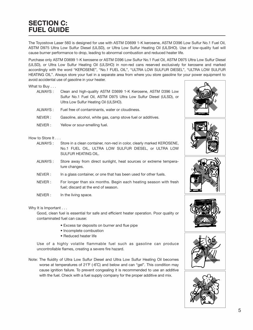
Clean and high-quality ASTM D3699 1-K Kerosene, ASTM D396 Low Sulfur No.1 Fuel Oil, ASTM D975 Ultra Low Sulfur Diesel (ULSD), or Ultra Low Sulfur Heating Oil (ULSHO).
Fuel free of contaminants, water or cloudiness.
Gasoline, alcohol, white gas, camp stove fuel or additives.
Yellow or sour-smelling fuel.
Store in a clean container, non-red in color, clearly marked KEROSENE, No.1 FUEL OIL, ULTRA LOW SULFUR DIESEL, or ULTRA LOW SULFUR HEATING OIL.
Store away from direct sunlight, heat sources or extreme tempera-ture changes.
In a glass container, or one that has been used for other fuels.
For longer than six months. Begin each heating season with fresh fuel; discard at the end of season.
In the living space.
• Excess tar deposits on burner and flue pipe• Incomplete combustion• Reduced heater life
What to Buy . . .ALWAYS :
ALWAYS :
NEVER :
NEVER :
How to Store It . . .ALWAYS :
ALWAYS :
NEVER :
NEVER :
NEVER :
Why It is Important . . .Good, clean fuel is essential for safe and efficient heater operation. Poor quality or contaminated fuel can cause:
Use of a highly volatile flammable fuel such as gasoline can produce uncontrollable flames, creating a severe fire hazard.
Note: The fluidity of Ultra Low Sulfur Diesel and Ultra Low Sulfur Heating Oil becomes worse at temperatures of 21˚F (-6˚C) and below and can “gel”. This condition may cause ignition failure. To prevent congealing it is recommended to use an additive with the fuel. Check with a fuel supply company for the proper additive and mix.
GAS
The Toyostove Laser 560 is designed for use with ASTM D3699 1-K kerosene, ASTM D396 Low Sulfur No.1 Fuel Oil, ASTM D975 Ultra Low Sulfur Diesel (ULSD), or Ultra Low Sulfur Heating Oil (ULSHO). Use of low-quality fuel will cause burner performance to drop, leading to abnormal combustion and reduced heater life.
Purchase only ASTM D3699 1-K kerosene or ASTM D396 Low Sulfur No.1 Fuel Oil, ASTM D975 Ultra Low Sulfur Diesel (ULSD), or Ultra Low Sulfur Heating Oil (ULSHO) in non-red cans reserved exclusively for kerosene and marked accordingly with the word “KEROSENE”, “No.1 FUEL OIL”, “ULTRA LOW SULFUR DIESEL”, “ULTRA LOW SULFUR HEATING OIL”. Always store your fuel in a separate area from where you store gasoline for your power equipment to avoid accidental use of gasoline in your heater.
5
Laser 560_Type A_US.qxd 15.3.26 16:15 ページ 5

SET ROOM
MIN.
HOUR AUTO
ON / OFF
SETTIMER
CHILD LOCK
Programmable System
˚F / ˚C
POWER SAVER
CLEARDAYSELECT
Before using heater, familiarize yourself with the following operating controls and part names.
5. POWER SAVER/DAY SELECT button
3. TIMER button
14. AM/PM indicator
9. AUTO indicator
10. TIMER indicator
11. POWER SAVER indicator
12. CHILD LOCK indicator
4. TEMP/TIMER/CLOCK/DAY set
6. CHILD LOCK/CLEAR button
2. AUTO button
13. BURNING MODE indicator
15. ˚F/˚C indicator
SECTION D:OPERATING CONTROLS AND PART NAMES
16. DAY of the week indicator
7. ˚F/˚C switch
Make a note of your heater’s serial number,located on the outside cabinet surface.Your heater’s serial number:
SERIAL NO.
1. ON/OFF button
8. ON lamp
17. Circulation fan Fan cover
19. Power supply cord
18. Roomtemperaturesensor
Exhaust outlet
Air inlet
Side door
Drip tray
Front panel
20. Plump bob
Carrying handle
Control panel
Adjusting leg
Pipe stopper
Red reset button
Fuel strainer (inside)
Circulation fan motor
Louver
6
Laser 560_Type A_US.qxd 15.3.26 16:15 ページ 6
1. ON/OFF button:
2. AUTO button:
3. TIMER button:
4. TEMP/TIMER/CLOCK/DAY set:
5. POWER SAVER/DAY SELECT button:
6. CHILD LOCK/CLEAR button:
7. ˚F/˚C switch:
8. ON lamp:
9. AUTO indicator:
10. TIMER indicator:
11. POWER SAVER indicator:
12. CHILD LOCK indicator:
13. BURNING MODE indicator:
14. AM/PM indicator:
15. ˚F/˚C indicator:
16. Day of the week indicator:
17. Circulation fan:
18. Room temperature sensor:
19. Power supply cord:
20. Plumb bob:
Main button turns heater on and off. When switched on, heater begins operation and combustion starts after preheat period.
The button turns weekly timer operation modes on and off which have been programmed into weekly timer.
The button turns weekly timer set mode on and off.
TEMP/TIMER/CLOCK/DAY set modes can be set by pressing the ▲MIN. or ▼HOUR buttons.
The button turns POWER SAVER operation mode on and off. When setting weekly timer, the button is used to select a day of the week.
The button turns CHILD LOCK operation mode on and off. When setting weekly timer, the CLEAR button is used.
C/F toggle switch.
Lit – Heater is in operation.Flashing – Pre-heating and pre-purging.
Lit – Weekly timer operation is in use.
Lit – Heater operating in weekly timer set mode.
Lit – Heater operation in POWER SAVER mode.
Lit – Heater operation in CHILD LOCK mode.
Lit – Heater operation at high, medium or low combustion.
Lit – Digital indicator shows current time.Flashing – Current time can be changed.
Lit – Digital indicator shows current temp.Flashing – Current temp can be changed.
Lit – Digital Indicator shows current day or timer day.
Three speed motor supplies high-capacity warm air flow during high combustion for heating room up quickly, and low or medium-capacity warm air flow during low or medium combustion for maintaining comfortable room temperature.
Constantly senses room temperature and supplies information to heater so that desired room temperature can be maintained.
For use in 120V, AC electrical outlet.
Allows user to check if heater is positioned evenly.
7
Laser 560_Type A_US.qxd 15.3.26 16:15 ページ 7

RE. # PART # DESCRIPTION RE. # PART # DESCRIPTION
1234567891011121314151617181920212223242526272829
3031323334353637383940414243444546474849505152535455565758
5960616263646566676869707172737475767778798081828384858687
2047044620475804204500072047497020475929204704602047046520475566204704632047047020470464204750722047804420470442204783432047802620478383204702181718758220479521204749202047041120475094204750932047583120475881204749922047043820470448
2047597120475983204759782047808220475977204702342047041920470441204785502047555120475552204704122047067820470679204702062047047620477414204704522047046920478373204749252047592220475722204759252047592420475923204740552045586220474050
20474039204740572047035320474053204502202047809120478090204706662047427220475874204785092047498320478366 20479987204755352047507120474163204798852047027320470475204704772047047820474977204749752047048420470651204798912047049520470499
Front panel assemblyCarrying handlePlumb bobAdjustable legDrip trayTop plate with tank lidTank lid with pinTank lid pinRight side panel with access doorLevel valve access door with pinLeft side panelFan coverHeat exchangerBurner assemblyBurner ringFuel nozzleFuel nozzle gasketIgniterIgniter gasketIgniter guide gasketIgniter coverPrimary flame rodBurner gasketHeat chamber gasketMica windowPeep window gasketJoint packingBlower motor assemblyBlower motor assembly with case
Blower motor exhaust fanBlower motor intake fanRubber matO-ring (Ø110)O-ring (Ø49)Fuel sumpFuel pumpFuel pipe assemblyFuel inlet strainerDrain screw with O-ringStrainer gasketMain circuit boardFuse 1 (5A)Fuse 2 (10A)High limit switch Operation panelPCB supportLeveler fuel pipeCirculation fan motorThermistorOil catchRemovable fuel tank with hoseRemovable fuel tank without hoseFuel supply hoseFuel tank capFuel gaugeScrew OScrew S2Screw C
Insulator AFlange nutScrew 4PScrew FScrew 4lScrew 1UScrew 1TScrew 4CScrew MWasher for blower motorHeat chamber assemblyOutlet adapterAir damper (Ø25)Draft tubePower supply cordCirculation fanScrew IOutside nozzle gasketBurner thermistorRibbon cable ARibbon cable circuit boardRibbon cable BHose bandL-shaped hoseBent jointInlet hoseFlue pipeInstruction manualCarton
RE. # PART # DESCRIPTION
54
53
211
63
44
58
58
13
58
56
74
59
66
1262
5848
4342
49
4146
8079
46
79
78
2
9
345
27
65
64
692526
75
24
15
2260
77
1417
7672
1658
23
735
58 71
2019
1821
58
58
32
28
31
58
70
2968
30 60
3458
33
4
50
36
37
62
47
35
61
58
38
39
40
58
78 10
57
87
1
34
5758
58
6
51
84
67
85
82 81
83
81 82
55
52
8
Laser 560_Type A_US.qxd 15.3.26 16:16 ページ 8
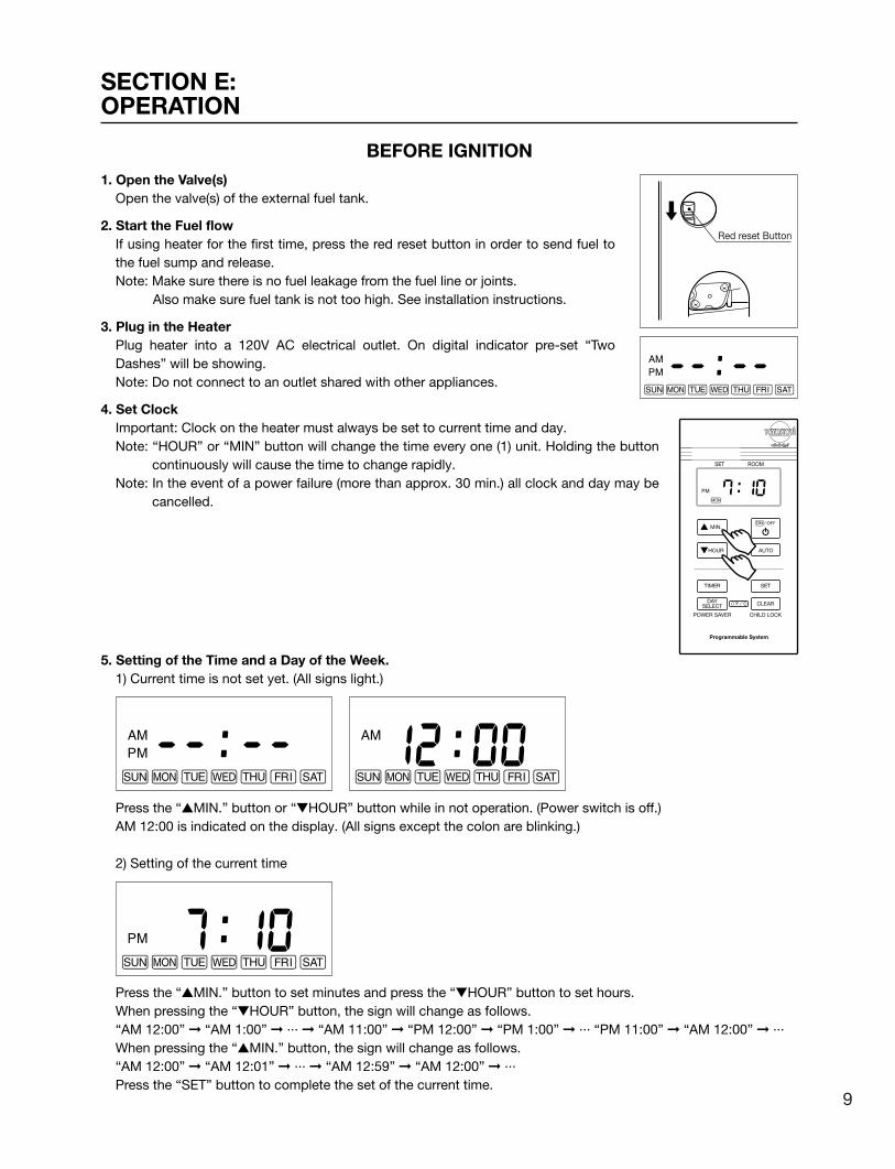
BEFORE IGNITION1. Open the Valve(s)
Open the valve(s) of the external fuel tank.
2. Start the Fuel flowIf using heater for the first time, press the red reset button in order to send fuel to the fuel sump and release.Note: Make sure there is no fuel leakage from the fuel line or joints.
Also make sure fuel tank is not too high. See installation instructions.
3. Plug in the HeaterPlug heater into a 120V AC electrical outlet. On digital indicator pre-set “Two Dashes” will be showing.Note: Do not connect to an outlet shared with other appliances.
4. Set ClockImportant: Clock on the heater must always be set to current time and day.Note: “HOUR” or “MIN” button will change the time every one (1) unit. Holding the button
continuously will cause the time to change rapidly.Note: In the event of a power failure (more than approx. 30 min.) all clock and day may be
cancelled.
5. Setting of the Time and a Day of the Week.1) Current time is not set yet. (All signs light.)
Press the “▲MIN.” button or “▼HOUR” button while in not operation. (Power switch is off.)AM 12:00 is indicated on the display. (All signs except the colon are blinking.)
2) Setting of the current time
Press the “▲MIN.” button to set minutes and press the “▼HOUR” button to set hours.When pressing the “▼HOUR” button, the sign will change as follows.“AM 12:00” ➞ “AM 1:00” ➞ ··· ➞ “AM 11:00” ➞ “PM 12:00” ➞ “PM 1:00” ➞ ··· “PM 11:00” ➞ “AM 12:00” ➞ ···When pressing the “▲MIN.” button, the sign will change as follows.“AM 12:00” ➞ “AM 12:01” ➞ ··· ➞ “AM 12:59” ➞ “AM 12:00” ➞ ···Press the “SET” button to complete the set of the current time.
SECTION E:OPERATION
SET ROOM
MIN.
HOUR AUTO
ON / OFF
SETTIMER
CHILD LOCK
Programmable System
˚F / ˚C
POWER SAVER
CLEARDAYSELECT
Red reset Button
9
Laser 560_Type A_US.qxd 15.3.26 16:16 ページ 9

SET ROOM
MIN.
HOUR AUTO
ON / OFF
SETTIMER
CHILD LOCK
˚F / ˚C
POWER SAVER
CLEARDAYSELECT
3) Setting of a day of the week
“dAy” sign is shown on the display and all of days of the week will blink.Press the “▲MIN.” button or the “▼HOUR” button to set a day of the week. A day of the week will blink. (Initial setting is “SUN”.) The other days of the week will go off. Select a day of the week by using the “▲MIN.” or the “▼HOUR” button. When pressing the “▲MIN.” button, the sign will change as follows.“SUN” ➞ “MON” ➞ “TUE” ➞ “WED” ➞ “THU” ➞ “FRI” ➞ “SAT”When pressing the “▲MIN.” button at the position of “SAT”, you can hear a beep sound and “SAT” is not changed any more. When pressing the “▼HOUR” button, the sign will change as follows.“SAT” ➞ “FRI” ➞ “THU” ➞ “WED” ➞ “TUE” ➞ “MON” ➞ “SUN”When pressing the “▼HOUR” button at the position of “SUN”, you can hear a beep sound and “SUN” is not changed any more.Press the “SET” button to complete the setting of the days of the week. The current time and a day of the week will show on the display.
Note: If the ON/OFF switch is pressed during setting of the current time and a day of the week after setting the time and a day of the week, the set mode of the current time will terminate and the operation will start. If a day of the week is set, the time is fixed. If a day of the week is not set, the contents of the setting are deleted.
OPERATION
MANUAL OPERATION
Operation of the heater is under the direct control of the user. Heat output will, however, be automatically adjusted in accordance with the room temperature registered by the temperature sensor.
1. Turn Heater ONA. Press ON/OFF button to “ON” position. The current room temperature and the set temperature will be
shown on the button digital indicator. ON lamp will start to flash and then blower motor and ignition will start. This lamp will continue to flash during the preheating time.
B. After approx. 1.5 – 4 minutes ignition will take place. (*) After ignition, ON lamp will change flashing to continuous. Circulation fan will turn on after approx. 2 minutes.Note: (*) Pre -heating depends on the room temperature.
Room temperature: below 34˚F Approx. 9 minutes34˚F - 61˚F " 6 minutesover 61˚F " 3 minutes
10
Laser 560_Type A_US.qxd 15.3.26 16:16 ページ 10

SET ROOM
MIN.
HOUR AUTO
ON / OFF
SETTIMER
CHILD LOCK
˚F / ˚C
POWER SAVER
CLEARDAYSELECT
SET ROOM
MIN.
HOUR AUTO
ON / OFF
SETTIMER
CHILD LOCK
˚F / ˚C
POWER SAVER
CLEARDAYSELECT
2. Adjusting Room TemperatureA. Press “HOUR” or “MIN.” button. ˚F or ˚C will start to flash.
Note: “HOUR” or “MIN.” button will change the temperature in increment of 2˚F (1˚C).
B. Press “MIN.” for up and “HOUR” for down. Room temperature can be set from 50˚F (10˚C) to 90°F (32˚C). (Initial setting : 56˚F (13˚C))
C. When room temperature reaches the selected setting, heater will automatically shift to “MED” or “LOW” burning mode to maintain the desired temperature.When room temperature exceeds the selected setting by approx. 4˚F (2˚C), the heater will automatically shut off. As room temperature drops, the heater will automatically re-start to maintain the desired temperature.
POWER SAVER OPERATIONThe Power Saver mode reduces the frequency of ignition actions, to save electric consumption.Press the POWER SAVER (DAY SELECT) button “ON” while in operation to start the operation of the “POWER SAVER”. “POWER SAVER” sign will be shown on the digital indicator.When the room temperature exceeds the selected setting by approximately 10˚F (6˚C), the heater will automatically shut off. As the room temperature becomes lower than the selected setting, the heater will automatically re-start to maintain the desired temperature.
Approx. +4˚F
Approx. +1˚F
SETTEMP.
High Medium Low Off Re-lgnition
Programmable System
Programmable System
11
Laser 560_Type A_US.qxd 15.3.26 16:16 ページ 11

SET ROOM
MIN.
HOUR AUTO
ON / OFF
SETTIMER
CHILD LOCK
˚F / ˚C
POWER SAVER
CLEARDAYSELECT
SET ROOM
MIN.
HOUR AUTO
ON / OFF
SETTIMER
CHILD LOCK
˚F / ˚C
POWER SAVER
CLEARDAYSELECT
CHILD LOCK OPERATIONPress the CHILD LOCK (CLEAR) button for more than 3 seconds to set the child lock while in operation or not in operation. “CHILD LOCK” sign will be shown on the digital indicator.
If the ON/OFF Switch is pressed while the Child Lock is on while in not operation, you can hear the beep sound, but the unit does not start. If the ON/OFF Switch is pressed while the Child Lock is on while in operation, the heater will automatically shut down with a beeping sound. “CHILD LOCK” on the digital indicator will flash and “OFF” will be shown on the digital indicator.
To release the warning, press the CHILD LOCK (CLEAR) button for more than 3 seconds.
Approx. +10˚F
Approx. +1˚F
SETTEMP.
High Medium Low Off Re-lgnition
Programmable System
Programmable System
12
Laser 560_Type A_US.qxd 15.3.26 16:16 ページ 12

WEEKLY TIMER OPERATION
1. Set the Weekly Timer
Note: The following programs are set at the factory in advance.
After setting the current time and a day of the week, press the “TIMER” button to enter the weekly timer setting mode. The “TIMER” is shown on the display. When the “TIMER” button is pressed during setting of the weekly timer, the “TIMER” sign disappeared and the current clock time and a day of the week are shown on the display.Note: You cannot enter the weekly timer setting mode, while in operation and AUTO operation mode, on.
1) Select the program number
Press the “▲MIN.” button or the “▼HOUR” button to select the program number.The number of program numbers is 30. The non-set program number will flash on the display. In case of the first setting of the weekly timer, “P01” is shown on the display and will blink. In case that the program is already set, the next number of the biggest setting program number is shown on the display. If the program is set until “P30”, “P30” is shown on the display and will blink. Even though all program number are set to “P30”, if there is any non-set program number, the smallest non-set program number is shown on the display.When pressing the “▲MIN.” button, the sign will change as follows.“P01” ➞ “P02” ➞ ··· ➞ “P29” ➞ “P30”When pressing the “▲MIN.” button at the position of “P30”, you can hear a beep sound and “P01” is not changed any more.When pressing the “▼HOUR” button, the sign will change as follows.“P30” ➞ “P29” ➞ ··· ➞ “P02” ➞ “P01”When pressig the “▼HOUR” button at the position of “P01”, you can hear a beep sound and “P01” is not changed any more.
Example:In case that “P01” and “P02” programs are set and “P03” is not set, the display shows as follows.“P01” – solid ⇔ “P02” – solid ⇔ “P03” – flashing 3In case that “P01” and “P04” programs are set and “P02” and “P03” are not set, the display is indicated as follows.“P01” – solid ⇔ “P02” – flashing 3 ⇔ “P03” – flashing 3 ⇔ “P04” – solid ⇔ “P05” – flashing 3
When a non-set program number is shown on the display, all of a day of the week will blink.Press the “SET” button to move to the next step (Set the timer).The program number memory is cleared by holding the “CLEAR” button continuously for 3 seconds.
Program #P01P02P03P04P05P06P07P08
Clock TimeAM 6:00AM 8:30PM 5:00PM 11:00AM 7:00AM 10:00PM 4:00PM 11:00
Temp.68˚F (20˚C)62˚F (16˚C)68˚F (20˚C)62˚F (16˚C)68˚F (20˚C)62˚F (16˚C)68˚F (20˚C)62˚F (16˚C)
Day“MON” “TUE” “WED” “THU” “FRI”“MON” “TUE” “WED” “THU” “FRI”“MON” “TUE” “WED” “THU” “FRI”“MON” “TUE” “WED” “THU” “FRI”
“SUN” “SAT”“SUN” “SAT”“SUN” “SAT”“SUN” “SAT”
13
Laser 560_Type A_US.qxd 15.3.26 16:16 ページ 13

2) Set the timer
The timer is shown on the display. (In the case that the timer time is not set, dashes are shown on the display.)Press the “▲MIN.” button or the “▼HOUR” button to set timer time. “AM 12:00” will be shown on the display. (The all signs except the colon will blink.)When pressing the “▼HOUR” button, the sign will change as follows.“AM 12:00” ➞ “AM 1:00” ➞ ··· ➞ “AM11:00” ➞ “PM 12:00” ➞ “PM 1:00” ➞ ··· ➞ “PM 11:00” ➞ AM 12:00” ➞ ···When pressing the “▲MIN.” button, the sign will change as follows.“AM 12:00” ➞ “AM 12:10” ➞ “AM 12:20” ➞ “AM 12:30” ➞ “AM 12:40” ➞ “AM 12:50” ➞ “AM 12:00” ➞ ···Press the “SET” button to complete the setting of the timer time and to move to the next step (Set the temperature of the Program Number).In case that the “SET” button is pressed when showing the bars sign on the display, you can hear the beep sound and cannot move to the next step.
3) Set the temperature of the Program Number
The set temperature “70” will be shown on the display and it will blink.Press the “▲MIN.” button or the “▼HOUR” button to set the temperature of the program. The “▲MIN.” button or the “▼HOUR” button will change temperature every 2˚F (1˚C).Press the “SET” button to complete the set the temperature of the program and move to the next step (Set a day/s of the week for the Program Number).
4) Set a day/s of the week for the Program Numver
The “dAy” sign will be shown on the display and the “SUN” will blink. Press the “▲MIN.” button or the “▼HOUR” button to set a day of the week, When pressing the “▲MIN.” button, that day is turned on. The day of the week will light and will more to the next day automatically. When pressing the “▼HOUR” button, that day is turned off. The day of the week will go off and will more to the next day automatically. When pressing the “DAY SELECT” button, the display will show the next day of the week without setting. The sign of a day of the week will change as follows.“SUN” ➞ “MON” ➞ “TUE” ➞ “WED” ➞ “THU” ➞ “FRI” ➞ “SAT” ➞ “SUN” ➞ ···Press the “SET” button to complete the set of a day of the week of the program and it will go back to the select of the program number. In case that a day of the week is not set, when pressing the “SET” button, you can hear a beep sound and cannot move to the next step.
14
Laser 560_Type A_US.qxd 15.3.26 16:16 ページ 14

SET ROOM
MIN.
HOUR AUTO
ON / OFF
SETTIMER
CHILD LOCK
˚F / ˚C
POWER SAVER
CLEARDAYSELECT
2. Activate Weekly Timer Operation
During operation (in ON position), press the “AUTO” button to turn on the weekly timer operation mode. However, if no program are set, you will hear the beep sound and cannot turn on the weekly timer operation mode. Press the “▲MIN.” button or the “▼HOUR” button to change the set temperature. However, if the next program starts, the temperature will be changed to the temperature of the next program.
During operation, press the “TIMER” button to enter the weekly timer set mode (Select the program number). If the “TIMER” button is pressed during the setting of the weekly timer set mode, the weekly timer set mode is turned off. Change of setting is applied as soon as the AUTO operation is turned on.
MANUAL COMBUSTION
Important: This feature is for testing purpose only!
This heater can also be kept burning at desired combustion mode (High, Medium or low) manually, regardless of room temperature.1. Press the “▲MIN.” button and “▼HOUR” button at the same time for more than three (3) seconds when ON /
OFF button is “ON”.2. P1, P2 or P3 will be displayed on the Digital Indicator;
P1 = Low modeP2 = Medium modeP3 = High mode
Then select desired combustion mode by pressing “▲MIN.” or “▼HOUR” button. “▲MIN.” button changes combustion mode to higher, “▼HOUR” button changes combustion mode to lower.
3. To clear, press the “▲MIN.” button and “▼HOUR” button at the same time for more than (3) seconds until normal temperature display returns.
AUTOMATIC CLEANING MODEWhen the heater has been burning continuously for two hours at its highest setting, the burner will automatically start an auto clean procedure. The display will show the auto cleaning code cl:05 running back to cl:01. The procedure takes 5 minutes to clean the burner automatically, while the heater will burn at its lowest setting. When the burner is clean again, the heater will automatically switch back to the highest setting again.
TURNING HEATER OFFPress ON/OFF button to “OFF” position. ON lamp will flash and will go out. Circulation fan and blower motor continue to run for approx. three (3) minutes to cool down the heater. Make sure ON lamp goes out when the fan stops. Programmable System
15
Laser 560_Type A_US.qxd 15.3.26 16:16 ページ 15

FOR OPTIMUM HEATER PERFORMANCE, THE PARTS SHOWN BELOW SHOULD BE CLEANED REGULARLY:
Check
Check
CAUTION: Be sure to turn off and unplug heater before performing any checks or cleaning.
CAUTION: Allow heater to cool completely before cleaning or maintenance.
Louver
Fan cover
Side door
SECTION F:ROUTINE MAINTENANCE
1. Clean Louvers (ONCE A MONTH)Dust and stains should be wiped off louvers with a damp cloth.
2. Clean Circulation Fan Cover (ONCE A MONTH)Remove only dust or pet hair from the cover on the back of the heater.
3. Check for Fuel Leaks (REGULARLY)Make it a habit to check for any sign of fuel leakage along the fuel line and at all joints. Fuel leaks may lead to risk of fire.
4. Check Flue Pipe Area (ONCE A MONTH)Check the flue pipe joint to make sure connection is firm. Use a vacuum cleaner to remove any dust or pet hair.
16
Laser 560_Type A_US.qxd 15.3.26 16:16 ページ 16

5. Clean Fuel Strainer (ONCE A SEASON)The strainer of the fuel sump should be cleaned once a season and before starting the heater at the beginning of each season.
(a) Close the valve closest to the heater.
(b) To catch the fuel which will drain out, set the Oil catch below the Strainer
cover, with a small container under it.
(c) Loosen the two screws from the Strainer cover and remove.
(d) Remove the strainer and wash with kerosene or fuel oil.
(e) Return the strainer to its original position. Replace strainer cover and screw
to secure.
(f) Wipe away any spilled fuel.
(g) Open the valve in the fuel line. Check for fuel leakage.
Note: At the end of each season unscrew the drain screw to remove all the remaining fuel from the fuel sump. Be sure to follow procedure A and B listed above and replance Drain screw.
6. Recommended Periodic MaintenanceAs a state-of-the-art furnace, your heater requires periodic inspection and service by an authorized technician to insure optimum, trouble free performance. This inspection should include: a combustion check; flue pipe check; burner assembly check; cleaning all necessary parts and replacing gaskets as needed. Please ask your authorized Toyostove dealer for details and scheduling. When using Ultra Low Sulfur Diesel (ULSD) or Ultra Low Sulfur Heating Oil the heater should be serviced at least every two years because the distillation of ULSHO is heavier than 1-K Kerosene and No. 1 Fuel Oil. When using 1-K Kerosene or Low Sulfur No. 1 Fuel Oil your heater can be serviced less frequently.
AUTOMATIC IGNITER CLEANING SYSTEMWhen the heater is on and clock is set (see “set Clock” on page 9), it will automatically stop and clean the igniter every day at 2:00 AM and will display “CL” on the digital indicator. After the cleaning mode is finished the heater will automatically re-ignite and continue to burn again.
The igniter cleaning mode helps prolong the igniter life.
MANUAL IGNITER CLEANING SYSTEMHeater will clean igniter for ten (10) minutes manually.
1. When ON/OFF switch is “OFF”, press the “SET” button and “CLEAR” button at the same time for more than three (3) seconds.
2. Display will appear “CL:10” on Digital Indicator. Cleaning will begin and end without any additional input.
Note: Cleaning igniter is important to prolong igniter life. It is recommended that the igniter be cleaned once a month if the time is not set.
DrainScrew
Oil catch
FuelStrainer
Strainergasket
Strainercover
17
Laser 560_Type A_US.qxd 15.3.26 16:16 ページ 17
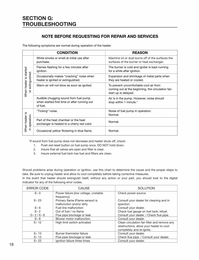
The following symptoms are normal during operation of the heater.
White smoke or smell at initial use afterpurchase.
Flames flashing for a few minutes afterignition.
Occasionally makes “cracking” noise whenheater is ignited or extinguished.
Part of the heat chamber or the heatexchanger is heated to a cherry red color.
Warm air will not blow as soon as ignited.
Audible chugging sound from fuel pumpwhen started first time or after running outof fuel.
“Ticking” noise.
Machine oil or dust burns off of the surfaces thesurfaces of the burner or heat exchanger.
The burner is cold and igniter is kept runningfor a while after ignition.
Expansion and shrinkage of metal parts whenthey are heated or cooled.
To prevent uncomfortable cool air fromcoming out at the beginning, the circulation fanstart up is delayed.
Air is in the pump. However, noise shouldstop within 1 minute.*
Noise of fuel pump in operation.Normal.
Normal.
Occasional yellow flickering in blue flame. Normal.
Whe
n he
ater
is s
tart
edor
ext
ingu
ishe
d.
Whe
n he
ater
isin
op
erat
ion.
CONDITION REASON
SECTION G:TROUBLESHOOTING
NOTE BEFORE REQUESTING FOR REPAIR AND SERVICES
ERROR CODEE– 0
E– 23
E– 6E– 2
E– 2 / E– 6E– 8
E– 12
E– 13E– 13E– 22
CAUSEPower failure (low voltage, unstable frequency)Primary flame (Flame sensor) is malfunction and/or dirtyFuel line malfunction Out of fuel / no flameFlue pipe blockage or leakBlower motor malfunctionHigh limit switch activated
Burner thermistor failureFlue pipe blockage or leakIgnition failure three times
SOLUTIONCheck power source.
Consult your dealer for cleaning and in spection.Consult your dealer.Check fuel gauge on fuel tank; refuel.Consult your dealer. / Check flue pipe.Consult your dealer.Clean circulation fan filter and remove any obstructions, allow your heater to cool completely and re-ignite.Consult your dealer.Check flue pipe. / Consult your dealer.Consult your dealer.
*If sound from fuel pump does not decrease and heater shuts off, check:1. Push red reset button on fuel sump once. DO NOT hold down.2. Insure that all valves are open and filter is clear.3. Insure external fuel tank has fuel and filters are clean.
Should problems arise during operation or ignition, use this chart to determine the cause and the proper steps to take. Be sure to unplug heater and allow to cool completely before taking corrective measures.In the event that heater should extinguish itself, without any action or your part, you should look to the digital indicator for any of the following error codes.
18
Laser 560_Type A_US.qxd 15.3.26 16:16 ページ 18
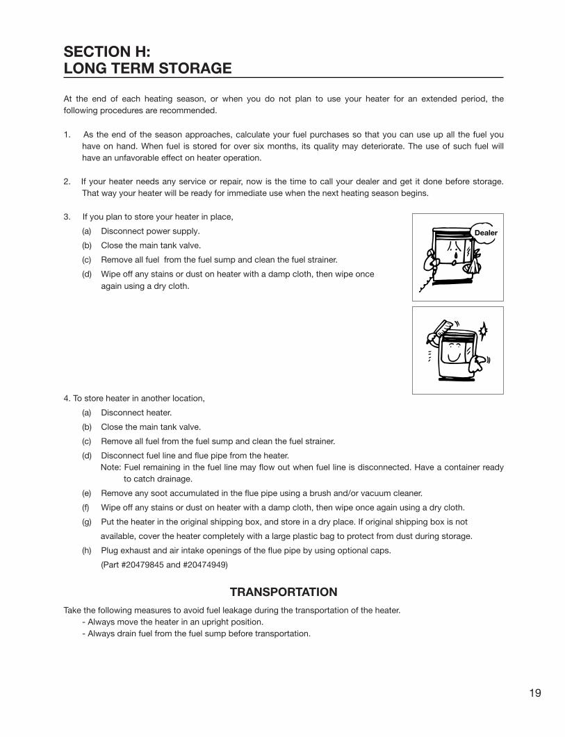
At the end of each heating season, or when you do not plan to use your heater for an extended period, the following procedures are recommended.
1. As the end of the season approaches, calculate your fuel purchases so that you can use up all the fuel you have on hand. When fuel is stored for over six months, its quality may deteriorate. The use of such fuel will have an unfavorable effect on heater operation.
2. If your heater needs any service or repair, now is the time to call your dealer and get it done before storage. That way your heater will be ready for immediate use when the next heating season begins.
3. If you plan to store your heater in place,
(a) Disconnect power supply.
(b) Close the main tank valve.
(c) Remove all fuel from the fuel sump and clean the fuel strainer.
(d) Wipe off any stains or dust on heater with a damp cloth, then wipe once again using a dry cloth.
4. To store heater in another location,
(a) Disconnect heater.
(b) Close the main tank valve.
(c) Remove all fuel from the fuel sump and clean the fuel strainer.
(d) Disconnect fuel line and flue pipe from the heater.Note: Fuel remaining in the fuel line may flow out when fuel line is disconnected. Have a container ready
to catch drainage.
(e) Remove any soot accumulated in the flue pipe using a brush and/or vacuum cleaner.
(f) Wipe off any stains or dust on heater with a damp cloth, then wipe once again using a dry cloth.
(g) Put the heater in the original shipping box, and store in a dry place. If original shipping box is not
available, cover the heater completely with a large plastic bag to protect from dust during storage.
(h) Plug exhaust and air intake openings of the flue pipe by using optional caps.
(Part #20479845 and #20474949)
TRANSPORTATIONTake the following measures to avoid fuel leakage during the transportation of the heater.
- Always move the heater in an upright position.- Always drain fuel from the fuel sump before transportation.
SECTION H:LONG TERM STORAGE
Dealer
19
Laser 560_Type A_US.qxd 15.3.26 16:16 ページ 19

SECTION I:INSTALLATION
TOOLS NEEDED FOR INSTALLATION
STANDARD INSTALLATION PARTS
The following standard installation parts are enclosed with heater. For alternate installation methods, you may need to purchase additional accessories which are available from your TOYOSTOVE dealer. See “Accessory Parts”, page 22.
Tool UsePhillips Head Screwdriver Installation of flue pipe, etc.Electric Drill Drilling hole in wall for flue pipeHole Saw, 2-3/4 to 3” diameter Making hole in wall for flue pipe
Exhaust Extension Pipe (S) (1) (PART #20479856)
Wall Brackets (2 sets) (PART #20474962)Drip Tray (1) (PART #20475929)
Pipe Stopper (1) (PART #20474964)
Pipe Holder (2) (PART #20474963)
20
Laser 560_Type A_US.qxd 15.3.26 16:16 ページ 20

Flue Pipe (1) (PART #20479891)Exhaust Air Cap (1) (PART #20479845)Intake Air Cap (1) (PART #20474949)Screw 4G (3) (PART #20474985)
Oil Catch (1) (PART #20474925)
Inlet Hose (1) (PART #20470651)
Spacer (1) (PART #20478967)Screw M (3) (PART #20474272)
Bent Joint (1) (PART #20470484) L-Shaped Hose (2) (PART #20474975)
Hose Band (2) (PART #20474977)
(3)
(3)
7-7/8”
3-1/8”
3-1/
8”
21
Laser 560_Type A_US.qxd 15.3.26 16:16 ページ 21

Fuel Lifter Pump Model OPT-91UL
PART #20477500
PART #20479872
PART #20474951
PART #20474950
PART #20479861
PART #20474955PART #20474954
Exhaust Extension Pipe
PART #20479887
3/81-3/8
Intake PipeJoint
Insulating cloth cover
Pipe SupportHardware
L-Shaped exhaust joint
Intake Pipe
PART #20479853
Adjustable Exhaust PipeMax. 39-3/8 ~ Min. 22-7/163/8 3/8 1-3/8
PART #20479887 Flue pipe ext. (for wall up to "9~13")PART #20479873 Flue pipe ext. (for wall up to "13~16")PART #20479874 Flue pipe ext. (for wall up to "16~20")PART #20479875 Flue pipe ext. (for wall up to "20~24")
Flue pipe extension
40 inch3-1/2
6-1/2 ft.
39-3/8
3-1/2
3-3 /
8
ACCESSORY PARTS
The following accessory parts are available for use in non-standard installation of the Laser 560. After giving careful consideration to your desired heater and flue pipe locations and fueling system, consult your TOYOSTOVE dealer to purchase the necessary accessory parts.Important: Use only genuine TOYOSTOVE parts for your heater. Use of unauthorized, generic or other brand
parts can severely reduce performance and safety, and will void factory warranty.
Accessory
Extension pipe kit (L)*
Extension pipe kit (M)*
Extension pipe kit (S)*
L-Shaped exhaust joint*
Fuel lifter pumpModel OPT-91UL
Pressure reducing valve
Part No.
20479898
20479897
20479896
20479861
20477500
10005099
Application
Extends pipe system from 61-3/4 to 78-3/4”
Extends pipe system from 22-1/2 to 39-3/8”
Extends pipe system from 12-5/8 to 19-5/8”
For 90 degree bend in exhaust pipe
Used to lift fuel to heater when fuel tank is located underground or outdoors in a position lower than the heater.With automatic recovery.
See Note on page 34.
* Total length of extension pipe between heater and flue pipe must be no greater than 10 ft. and no more than three bends may be used in extension pipe.
8 1/2 ft.maximum16 in.
minimumLess than26 ft. (8 m)
Less than23 ft. (7 m)
Heater
Return pipe
Required clearance
Oil level in fullFuel tank
Heater
8 1/2 ft.maximum16 in.
minimum
Outlet side
Less than 20 in. (50 cm)
Less than26 ft. (8 m)
Inlet sidefuel tank
22
Laser 560_Type A_US.qxd 15.3.26 16:16 ページ 22

When using the “Extension pipe (L)” extension kit, the distance between the heater exhaust pipe connection and the flue pipe connection must be at least 63-5/8 inch but no more than 80-1/2 inch. (See Figure 1 for reference.)
Extension Pipe Kit (L) PART #20479898
No. Name of Part Q’ty
1
2
3
4
5
6
7
Adjustable Exhaust PipeMax. 39-3/8~ 22-7/16
Exhaust Extension Pipe(long, 39-3/8 inch)
Intake Pipe (80 inch)
Insulating cloth cover(40 inch)
Pipe Holder
Pipe Support Hardware
L-Shaped Exhaust Joint
1
1
1
2
2
3sets
1
NOTE: Use “L”-shaped Exhaust Joint if necessary.
INSTALLATION WITH EXTENSION PIPE KIT (L)
AdjustableExhaust Pipe
Insulationcloth cover
Exhaust ExtensionPipe (long)
Pipeholder
Intake Hose
Pipe SupportHardware
(# 20479861) (# 20474963)
(# 20474950)
(# 20479853)
(# 20479872)
(# 20474951)
(# 20474955)
Pipe Support Hardware
Pipe Holder (2 pcs.)
Pipe Holder Support (1 pc.)
Screw(1 pc.)
Wood Screw(2 pcs.)
Nut (1 pc.)
7 5
6
3-3 /
8
3-1/2
1
2
3
4
40 inch
80 inch
39-3/8 inch
Max. 39-3/8 ~ Min. 22-7/16 inch
Flue pipe connection
IntakeHose
HeaterExhaustpipeconnection
Figure 1
63-5/8
~ 80-1/2
EXTENSION KIT
23
Laser 560_Type A_US.qxd 15.3.26 16:16 ページ 23

When using the “Extension pipe (M)” extension kit, the distance between the heater exhaust pipe connection and the flue pipe connection must be at least 25-5/8 inch but no more than 42-1/2 inch. (See Figure 2 for reference.)
No. Name of Part Q’ty
1
2
3
4
5
6
Adjustable Exhaust PipeMax. 39-3/8~ Min. 22-7/16
Intake Pipe (40 inch)
Insulating cloth cover(40 inch)
Pipe Holder
Pipe Support Hardware
L-Shaped Exhaust Joint
1
1
1
1
2sets
1
When using the “Extension pipe (S)” extension kit, the distance between the heater exhaust pipe connection and the flue pipe connection must be at least 15-3/4 inch but no more than 22-3/4 inch. (See Figure 3 for reference.)
Extension Pipe Kit (S) PART #20479896
No. Name of Part Q’ty
1
2
3
4
5
6
Adjustable Exhaust PipeMax. 19-11/16~ Min. 12-5/8
Intake Pipe (20 inch)
Insulating cloth cover(40 inch)
Pipe Holder
Pipe Support Hardware
L-Shaped Exhaust Joint
1
1
1
1
1sets
1
(# 20479861) (# 20474963)
(# 20474950)(# 20479853)
(# 20474951)
(# 20474955)
Pipe Support Hardware
Pipe Holder (2 pcs.)
Pipe Holder Support (1 pc.)
Screw(1 pc.)
Wood Screw(2 pcs.)
Nut (1 pc.)
6 4
5
3-3 /
8
3-1/2
(# 20479861) (# 20474963)
(# 20474950)Pipe Support Hardware
Pipe Holder (2 pcs.)
Pipe Holder Support (1 pc.)
Screw(1 pc.)
Wood Screw(2 pcs.)
Nut (1 pc.)
6 4
5
3-3 /
8
3-1/21
2
3
Max. 39-3/8 ~ Min. 22-7/16 inch
40 inch
40 inch
(# 20479858)
(# 20474951)
(# 20474955)
6
1
2
3
Max. 19-11/16 ~ Min. 12-5/8 inch
20 inch
40 inch
Flue pipe connection
IntakeHose
HeaterExhaustpipeconnection
Figure 2
Flue pipe connection
IntakeHose
HeaterExhaustpipeconnection
Figure 3
15-3/4~ 22-3/4
25-5/8~ 42-1/2
Extension Pipe Kit (M) PART #20479897
Snow
24
Laser 560_Type A_US.qxd 15.3.26 16:16 ページ 24

Important:
In open area with strong wind, a wind break may be necessary.
Follow the safety tips below when planning the installation of your Laser 560.
1. Intake and exhaust flue pipe openings must be fully exposed to outside air. Do not vent into chimney, garage, basement under the floor, or into any enclosed area.
2. Do not install flue pipe in close proximity to other objects or materials (See page 26).
3. Before making a hole in your wall for the flue pipe, make sure the area is free of electrical wires, gas pipes and other obstacles.
4. Do not install flue pipe where it will be exposed to heavy snow collected leaves or strong drafts.
5. Do not install the flue pipe down from the heater.
6. Total length of extension pipe between heater and flue pipe must be no greater than 10 ft. and no more than 3 bends.NOTE: When using extension pipes always cover the exhaust pipe with the
insulating cloth cover.
7. B-Vent shall not be used in the vent system.For all prescribed heater installations, the flue pipe must always be installed in a horizontal position.
SAFETY TIPS FOR INSTALLATION
Longextensionkit
SnowSnow
Must behigher
24"(Min.)
Windbreak
Strongwind
Gas
olin
e
Ker
o-se
ne
Gas pipe
Important:
In areas of hea-vy snow falls, ground surface clearance must be increased according to average snow falls.
25
Laser 560_Type A_US.qxd 15.3.26 16:16 ページ 25

Fig. 2 <Standard Flue Pipe Installation> Fig. 3
Object combustible
Not less than 2 ft.
Combustible object
Noncombustible object
Not less than 1 ft.
Flue pipe
* Not less than 8 in.
45˚
Not less than 1.5 ft.
Not less than1.5 ft.
Fig. 1
IMPORTANT: Check and comply with all state and local codes that may apply to vented heaters before beginning installation.
NOTE: This heater is designed to be used at altitudes up to 3,000 ft. above sea level.For use at altitudes higher than 3,000 FT. and up to 6,000 FT., adjustments to the heater must be made. Consult with your dealer.
MINIMUM CLEARANCE TO COMBUSTIBLE AND NONCOMBUSTIBLE CONSTRUCTION
1. Select heater location. Allow clearances as indicated below between heater and all other materials.(See Fig. 1)
Note: These clearance are necessary to allow properly circulation and to have heater work affectively.
2. Make sure that the outside area to where the flue pipe will reach is clear of any objects.
(See Fig. 2 & 3)
CAUTION! The standard flue pipe installation, as shown in Fig. 2, is for wall thickness from 4 in. to 9 in. ONLY.Note: For wall thickness more than 9 in., refer to page 22 for available flue pipe extensions.Note: The flue pipe can be installed through any standard building materials.
* Be sure thisclearance willbe maintainedafter snow-falls, etc.
More than 5 ft.
More than 1 ft.
More than 4 inches
More than 1 ft.
More than4 inches
More than 1 ft.
More than 2 ft.
26
Laser 560_Type A_US.qxd 15.3.26 16:16 ページ 26

More than 1 ft.
More than 4 inches
3. For standard installation, use the template enclosed with the heater to position the hole for the flue pipe. Tack or tape template to the wall at the desired position (See Fig. 4).
NOTE: Heater should be installed on a sturdy floor that is level and flat.
4. Cut the hole for the flue pipe from inside the room. Use a 2-3/4 to 3” diameter hole saw attached to an electric drill (See Fig. 5). The opening on the inside wall should be slightly higher than the outside opening (approximately 1/4”) so that the flue pipe will slope slightly downward (approximately 2 degrees) after it is installed (See Fig. 6). This will enable the draining of condensed moisture from the flue pipe to the outside and prevent rain or snow entering from outside after installation.
NOTE: After the cutting of the hole is completed, remove the template from the wall.
Fig. 4
Tape
2˚ downward Min.
Fig. 5 Fig. 6
27
Laser 560_Type A_US.qxd 15.3.26 16:16 ページ 27

5. Install the inner flue pipe.a. For wall thickness 5-3/16” to 9”
From inside the room, insert the inner flue pipe through the hole. Make sure the arrow on the inner flue pipe is pointing up. Secure the inner flue pipe to the wall with the three wood screws.(See Fig. 7.)
b. For wall thickness 4” to 5-3/16”In the event that the wall is too thin, use the spacer as indicated in Fig. 8.
c. From outside, insert the outer flue pipe through the hole. Secure the outer flue pipe to the wall by turning it clockwise. This locks the two halves together (See fig. 9).
IMPORTANT: Make sure the arrow on the outer flue pipe flange is pointing up.Make sure to secure the outer flue pipe well. (A-part shown in Fig. 9)Check inside flue pipe for insulation and remore if any.
Fig. 7
Fig. 8
Fig. 9
Inner flue pipe
Wood screws
Arrow
Inside Outside
5-3/16” to 9”
2˚ downward Min.
Inner flue pipe
Inside Outside
Arrow2˚ downward Min.
Outer flue pipe flange
A
Outer flue pipe
Outer flue pipe flange
Inner flue pipe
Wood screws
Arrow
Inside Outside
4” to 5-3/16”
2˚ downward Min.
Spacer
Tapping screws
Spacer
28
Laser 560_Type A_US.qxd 15.3.26 16:16 ページ 28
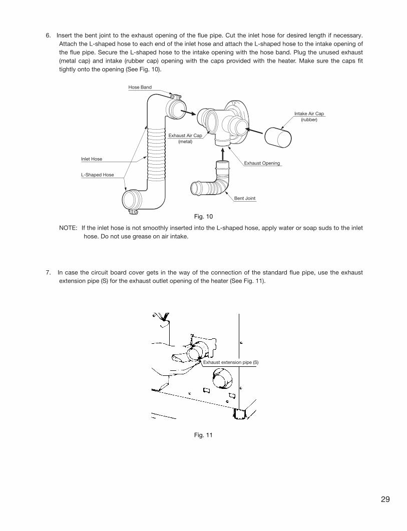
6. Insert the bent joint to the exhaust opening of the flue pipe. Cut the inlet hose for desired length if necessary. Attach the L-shaped hose to each end of the inlet hose and attach the L-shaped hose to the intake opening of the flue pipe. Secure the L-shaped hose to the intake opening with the hose band. Plug the unused exhaust (metal cap) and intake (rubber cap) opening with the caps provided with the heater. Make sure the caps fit tightly onto the opening (See Fig. 10).
NOTE: If the inlet hose is not smoothly inserted into the L-shaped hose, apply water or soap suds to the inlet hose. Do not use grease on air intake.
7. In case the circuit board cover gets in the way of the connection of the standard flue pipe, use the exhaust extension pipe (S) for the exhaust outlet opening of the heater (See Fig. 11).
L-Shaped Hose
Hose Band
Exhaust Air Cap(metal)
Intake Air Cap(rubber)
Exhaust Opening
Bent Joint
Inlet Hose
Fig. 11
Fig. 10
Exhaust extension pipe (S)
29
Laser 560_Type A_US.qxd 15.3.26 16:16 ページ 29

Fig. 13
8. Move the heater into position. Connect the bent joint to the exhaust outlet opening (upper opening) and attach the L-shaped hose to the intake inlet opening. Make sure all connections are tight (See Fig. 12).
9. Secure the L-shaped hose to the intake inlet opening with the hose band. Secure the bent joint to the flue pipe with the pipe holder (If the extension pipe is used, also attach the pipe holder to the connection of the bent joint and the extension pipe). Secure the bent joint (or the extension pipe) to the exhaust outlet opening by sliding the pipe stopper in the exhaust opening bracket (See Fig. 13).
Outlet Opening
Inlet Opening
Bent Joint
L-Shaped Hose
Pipe stopper
Pipe holder
Fig. 12
30
Laser 560_Type A_US.qxd 15.3.26 16:16 ページ 30

10. Make sure the position of the heater is level by using the plumb bob located at the right side of the heater. The plumb bob weight should be within the circle. If the plumb bob weight is not within the circle, adjust the heater legs until the plumb bob weight is within the red circle (See Fig. 14 & 15).
11. A room temperature sensor is provided with approx. eight (8) feet long extension wire. It is located on the rear of the cabinet. Make sure that the extension wire is not touching the exhaust pipe. The room temperature sensor can be installed either with the self adhesive tape on the back or with a wood screw provided with the sensor depending on the type of surface chosen for installation.NOTE: Choose a location for the sensor that is not in the path of direct sunlight, drafts or the flow of warm air
from the heater.
(a) Self Adhesive TapePeel off the protective tape on the back of the sensor and expose the adhesives. Place the sensor on the desired location on the wall and press down.
(b) Wood ScrewScrew down the wood screw provided with the heater into the desired location on the wall. Hook the back of the room temperature sensor.
12. After installation is completed, secure heater to the wall with the wall brackets provided with the heater. Make sure the heater is parallel to the wall (See Fig. 16).
13. Before ignition, recheck the following:a. All connections are tight and firm.b. The heater and the flue pipe areas are free of any materials.c. The heater is level and parallel to the wall.
Fig. 14 Fig. 15
Fig. 16
Good
Bad
Plumb bob as viewed from above
Circle
Weight
31
Laser 560_Type A_US.qxd 15.3.26 16:16 ページ 31

NOTE: Emergency power supply and use of 12V DC batteries with an inverter. Consult your dealer before attempting to use a battery/inverter system to provide power for your Laser heater. These units require true sine wave power for proper long-term operation. Some types of modified or block sine wave inverters will cause damage to the electrical components of the heater. Several inverter manufacturers offer true sine wave inverters which should operate the unit without any problems if properly sized and configured. If you have any questions about appropriate power supply, consult your authorized TOYOSTOVE dealer.
WARNING: MAKE SURE POWER SUPPLY CORD IS DISCONNECTED TO AVOID ANY ELECTRIC SHOCK
BEFORE SERVICING. ELECTRIC SHOCK MAY CAUSE SERIOUS INJURY.
INSTALLATION SHOULD BE CONDUCTED BY A LICENSED ELECTRICIAN.
Step 1.Disconnect power supply cord from power source.Remove three (3) screws and control box cover on the back of the heater.
Step 2.Disconnect ground wire (green wire) from the power supply cord bracket.
Step 3.Disconnect two powersupply wires from right side of the terminal.
Step 4.Squeeze strain relief with the adjustable pliers to remove plastic bushing from the pow-er supply cord bracket.Remove the power supply cord.
Step 5.Insert the power supply cable from junction box and con-nect ground wire to the power supply cord bracket and pow-er wires to theterminal.
Step 6.Affix the control box cover to the heater and insert screws.
PERMANENT WIRING INSTALLATION
32
Laser 560_Type A_US.qxd 15.3.26 16:16 ページ 32

SECTION J:FUELING
Laser 560 FUEL SYSTEM OPTIONS• Large Capacity External Tank
Tank must be purchased separately and installed by a qualified fuel supply technician.
EXTERNAL TANK INSTALLATIONNOTE: External tank installation must comply with National Fire Protection Association Code NFPA 31, CSA
Standard B139, the Installation Code for Oil Burning Equipment, or locally applicable codes. Check with
local building officials.
The following instructions should be followed for installation of a large capacity, gravity-fed external fuel tank.
• Installation height of tank's fuel outlet should be at least 16 in. above floor surface upon which heater
rests.
• To avoid excess fuel pressure to heater, top of fuel tank should be no more than 8-1/2 ft. above floor
surface upon which heater rests.
• Fuel tank should be located at least 6 ft. away from all heat sources.
• 3/8” OD copper tubing should be used for fuel line.
• To prevent air locks in fuel line, fuel line should be smooth with no U-shaped or sharp bends.
• Install a UL listed fuel filter at the fuel tank outlet (it is highly recommended to use an in-line small
mesh size filter with water block, e.g. 10 micro filter). Shut-off valves should also be installed on the
fuel line and connected the tank as illustrated on page 34.
NOTE: An additional shut-off valve installed next to the heater will minimize fuel to be drained should heater have to
be disconnected. If the valve is on interior side, a fusible link type is recommended.
1. Be sure all external tanks have an operating vent.
2. Be sure to observe the maximum and minimum tank heights as specified.
NOTE: If the maximum height from the top of the fuel tank to the bottom of the heater exceeds 8-1/2 ft., a fuel
pressure reducing valve, preset at 2.5 psi, is required.
Pressure Reducing Valve Part#10005099 has 3/8 in. (N.P.T.) inlet and outlet female openings to accept the
fuel line fittings.
WARNING: Use only ASTM D3699 1-K kerosene, ASTM D396 Low Sulfur No.1 Fuel Oil, ASTM D975 Ultra Low Sulfur Diesel (ULSD), or Ultra Low Sulfur Heating Oil (ULSHO). NEVER USE GASOLINE. Use of gasoline can lead to uncon-trollable flames resulting in destructive fire.
33
Laser 560_Type A_US.qxd 15.3.26 16:16 ページ 33
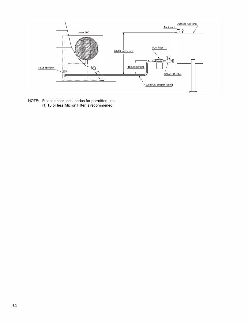
Laser 560
Shut off valve
81/2ft.maximum
Tank ventOutdoor fuel tank
Shut-off valve
3/8in.OD copper tubing
NOTE: Please check local codes for permitted use.(1) 15 or less Micron Filter is recommened.
Fuel filter (1)
16in.minimum
34
Laser 560_Type A_US.qxd 15.3.26 16:16 ページ 34

35
Monday
Tuesday
Wednesday
Thursday
Friday
Saturday
Sunday
PROGRAM #
123456789
101112131415161718192021222324252627282930
TIME DAY
(Tue.)
(Wed.)
(Thu.)
(Fri.)
(Sat.)
(Sun.)
(Mon.)
0 6 12 18 0
0 6 12 18 0
0 6 12 18 0
0 6 12 18 0
0 6 12 18 0
0 6 12 18 0
0 6 12 18 0
TEMPERATURE
CUSTOMER’S RECORD
PROGRAM MANAGEMENT TABLE
Laser 560_Type A_US.qxd 15.3.26 16:16 ページ 35

Rev. 04/15Part #20470495 Printed in Japan
TOYOTOMI U.S.A., INC.("TOYOTOMI") warrants each product and any parts thereof sold by it to be free from defects in materials or workmanship under normal use and service for TWELVE (12) MONTHS* from the date of delivery to the original purchaser at retail subject to the following terms and conditions :
WHAT IS COVERED : Product or any parts thereof which are defective in materials of workmanship.
WHAT IS NOT COVERED :(1) This warranty does not extend to any defect due to the negligence of others: failure to install, operate, or maintain unit in accordance with instructions (Installation and Operation instructions are furnished with each new unit); unreasonable use; accidents; alteration, use of unauthorized or non-standardized TOYOTOMI parts and accessories; electrical malfunction, i.e., as resulting from large power surges, short circuit, etc.; incorrect installation; use of any fuel other than that specified in owner's manuals; or repair by anyone other than a service facility specified by TOYOTOMI.(2) Normal wear and tear of parts, including hoses, wires, burner mats, fuel nozzles, filters and accessories.(3) This warranty does not cover shipping costs.
WHO IS COVERED : The original purchaser at retail.
WHAT WE WILL DO : TOYOTOMI will either repair or replace, at its option, all defective parts free of charge that are covered by this limited warranty on a carry-in basis, to your nearest authorized dealer or distributor of TOYOTOMI.
WHAT YOU MUST DO FOR WARRANTY SERVICE : You must return the defective Product or part to any authorized dealer or distributor of TOYOTOMI with this LIMITED WARRANTY and a copy of your bill of sale or credit card charge receipt or other documents evidencing the date of the Product's delivery, if service is not available locally, please contact our CUSTOMER RELATIONS DEPARTMENT at :
TOYOTOMI U.S.A., INC.604 Federal Road, Brookfield, CT 06804
(203)775-1909
THE FOREGOING EXPRESSES ALL OF TOYOTOMI'S OBLIGATIONS AND LIABILITIES WITH RESPECT TO THE QUALITY OF PRODUCT FURNISHED BY IT. ALL OTHER WARRANTIES, EXPRESSED OR IMPLIED, INCLUDING THE WARRANTIES OF MERCHANTABILITY OR FITNESS FOR A PARTICULAR PURPOSE ARE DISCLAIMED. TOYOTOMI SHALL NOT BE LIABLE FOR THE LOSS OF USE OF THE PRODUCT, INCONVENIENCE, LOSS OR ANY OTHER DAMAGES, DIRECT OR CONSEQUENTIAL ARISING OUT OF, THE USE OF, OR INABILITY TO USE, THE PRODUCT OR DAMAGES RESULTING FROM OR ATTRIBUTABLE TO DEFECTS IN THE PRODUCT.
No one other than TOYOTOMI has authority to extend or modify the terms of this Limited Warranty in any manner whatsoever.
Some states or provinces do not allow the exclusion or limitation of incidental or consequential damages or limitations on how long an implied warranty lasts, so these limitations or exclusions may not apply to you. This Limited Warranty gives you specific legal rights and you may also have other rights that vary from state to state, or province to province.
* In addition to the warranty period stated above, an extended two (2) year warranty (3 years from date of purchase) is on for the following parts. :
A. Burner PotB. Heat Chamber (Excluding Glass Cylinder)C. Heat Exchanger
NOTE : THE EXTENDED WARRANTY POLICY IS APPLICABLE ONLY FOR THE REPLACEMENT OF THE ORIGINAL FACTORY-INSTALLED PARTS THAT HAVE FAILED WITHIN THE TIME LIMITATIONS AS INDICATED. REPLACEMENT PARTS ARE WARRANTED FOR THE REMAINDER OF THE ORIGINAL PART WARRANTY PERIOD. LABOR IS NOT COVERED ON THE EXTENDED WARRANTY.
8369002060
LIMITED WARRANTY
TOYOTOMI U.S.A., INC.604 Federal Road, Brookfield, CT 06804
www.toyotomiusa.com
Laser 560_Type A_US.qxd 15.3.26 16:16 ページ 36