large diameter diaphragm wall shafts
TRANSCRIPT
RECENT ADVANCES IN LARGE DIAMETER DIAPHRAGM WALL SHAFTS Benoit Virollet and Christian Gilbert, Soletanche-Bachy, Nantarre, France, and Rick Deschamps, Nicholson Construction, Pittsburgh, PA
Over the last 10 years the diameter of unbraced, unlined and unanchored circular shafts has grown dramatically in many parts of the world. This progress has taken place through improvements in: construction methods; concrete rheology; and design capabilities. Excavation equipment has become more precise in terms of operator control and ability to correct alignment of digging elements leading to better alignment tolerances. Also contributing to the increases in shaft diameters is the evolution of design models. A better understanding of soil structure interaction is being incorporated into the analyses in terms of radial soil stresses and imposed loads on the shaft. This paper provides an overview of the recent progress made in circular shaft construction, the primary design considerations, and some innovative uses of efficient arc elements to develop unsupported structures of other shapes. In addition, a summary of recent circular shafts constructed worldwide is provided.
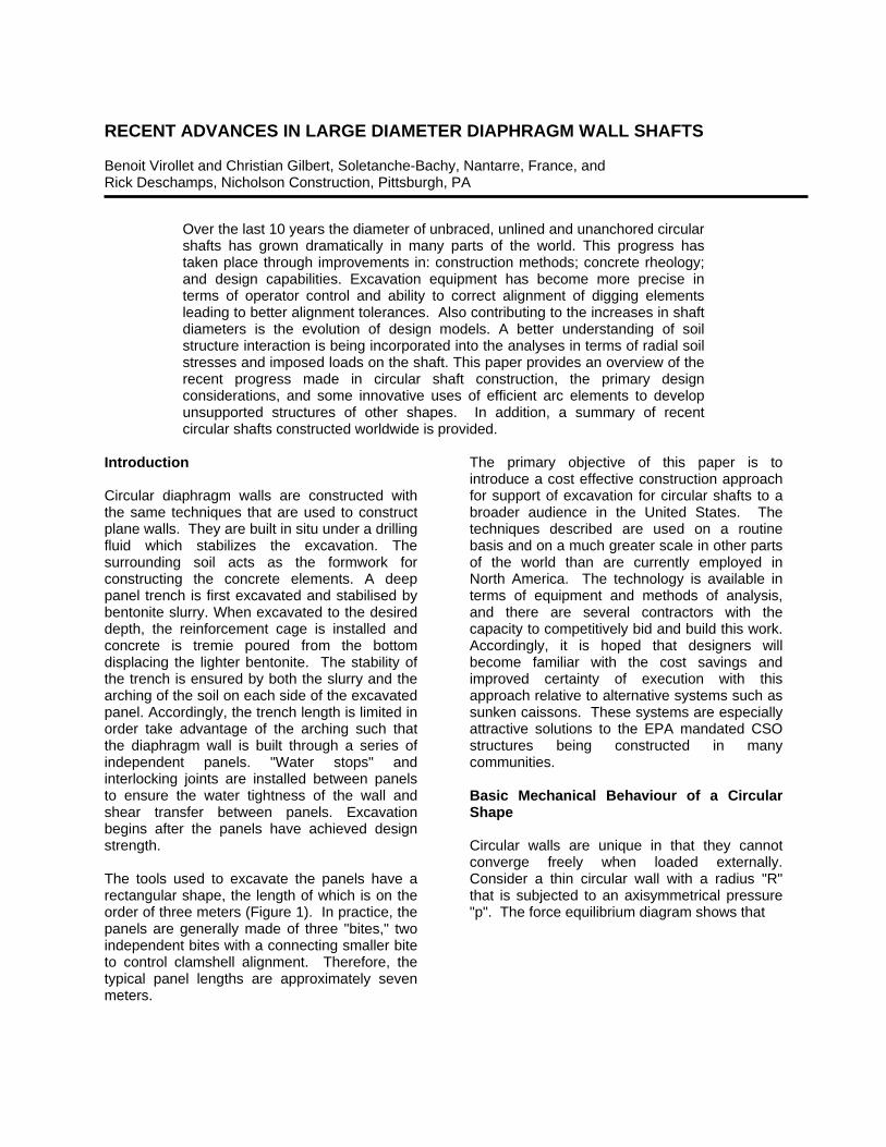
Introduction Circular diaphragm walls are constructed with the same techniques that are used to construct plane walls. They are built in situ under a drilling fluid which stabilizes the excavation. The surrounding soil acts as the formwork for constructing the concrete elements. A deep panel trench is first excavated and stabilised by bentonite slurry. When excavated to the desired depth, the reinforcement cage is installed and concrete is tremie poured from the bottom displacing the lighter bentonite. The stability of the trench is ensured by both the slurry and the arching of the soil on each side of the excavated panel. Accordingly, the trench length is limited in order take advantage of the arching such that the diaphragm wall is built through a series of independent panels. "Water stops" and interlocking joints are installed between panels to ensure the water tightness of the wall and shear transfer between panels. Excavation begins after the panels have achieved design strength. The tools used to excavate the panels have a rectangular shape, the length of which is on the order of three meters (Figure 1). In practice, the panels are generally made of three "bites," two independent bites with a connecting smaller bite to control clamshell alignment. Therefore, the typical panel lengths are approximately seven meters.
The primary objective of this paper is to introduce a cost effective construction approach for support of excavation for circular shafts to a broader audience in the United States. The techniques described are used on a routine basis and on a much greater scale in other parts of the world than are currently employed in North America. The technology is available in terms of equipment and methods of analysis, and there are several contractors with the capacity to competitively bid and build this work. Accordingly, it is hoped that designers will become familiar with the cost savings and improved certainty of execution with this approach relative to alternative systems such as sunken caissons. These systems are especially attractive solutions to the EPA mandated CSO structures being constructed in many communities. Basic Mechanical Behaviour of a Circular Shape Circular walls are unique in that they cannot converge freely when loaded externally. Consider a thin circular wall with a radius "R" that is subjected to an axisymmetrical pressure "p". The force equilibrium diagram shows that
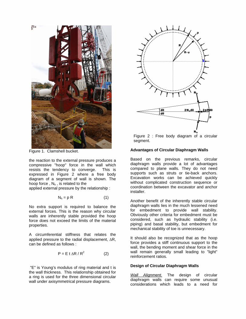
the reaction to the external pressure produces a compressive "hoop" force in the wall which resists the tendency to converge. This is expressed in Figure 2 where a free body diagram of a segment of wall is shown. The hoop force , Nh , is related to the applied external pressure by the relationship : Nh = p R (1) No extra support is required to balance the external forces. This is the reason why circular walls are inherently stable provided the hoop force does not exceed the limits of the material properties. A circumferential stiffness that relates the applied pressure to the radial displacement, ∆R, can be defined as follows : P = E t ∆R / R2 (2) "E" is Young’s modulus of ring material and t is the wall thickness. This relationship obtained for a ring is used for the three dimensional circular wall under axisymmetrical pressure diagrams.
Advantages of Circular Diaphragm Walls Based on the previous remarks, circular diaphragm walls provide a lot of advantages compared to plane walls. They do not need supports such as struts or tie-back anchors. Excavation works can be achieved quickly without complicated construction sequence or coordination between the excavator and anchor installer. Another benefit of the inherently stable circular diaphragm walls lies in the much lessened need for embedment to provide wall stability. Obviously other criteria for embedment must be considered, such as hydraulic stability (i.e. piping) and basal stability, but embedment for mechanical stability of toe is unnecessary. It should also be recognized that as the hoop force provides a stiff continuous support to the wall, the bending moment and shear force in the wall remain generally small leading to "light" reinforcement ratios. Design of Circular Diaphragm Walls Wall Alignment. The design of circular diaphragm walls can require some unusual considerations which leads to a need for
Figure 1. Clamshell bucket.
R
R-u
u
dθdθ
Nh
Nh
2Nhdθ
p
2pRdθ
p
R
R-u
u
dθdθ
Nh
Nh
2Nhdθ
p
2pRdθdθdθ
Nh
Nh
2Nhdθ
p
2pRdθ
p
Figure 2 : Free body diagram of a circular segment.
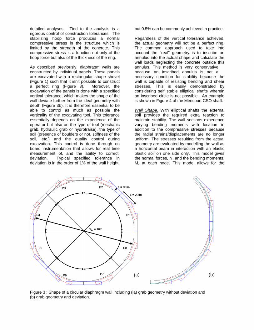
detailed analyses. Tied to the analysis is a rigorous control of construction tolerances. The stabilizing hoop force produces a normal compressive stress in the structure which is limited by the strength of the concrete. This compressive stress is a function not only of the hoop force but also of the thickness of the ring. As described previously, diaphragm walls are constructed by individual panels. These panels are excavated with a rectangular shape shovel (Figure 1) such that it isn't possible to construct a perfect ring (Figure 3). Moreover, the excavation of the panels is done with a specified vertical tolerance, which makes the shape of the wall deviate further from the ideal geometry with depth (Figure 3b). It is therefore essential to be able to control as much as possible the verticality of the excavating tool. This tolerance essentially depends on the experience of the operator but also on the type of tool (mechanic grab, hydraulic grab or hydrofraise), the type of soil (presence of boulders or not, stiffness of the soil, etc.) and the quality control during excavation. This control is done through on board instrumentation that allows for real time measurement of, and the ability to correct, deviation. Typical specified tolerance in deviation is in the order of 1% of the wall height,
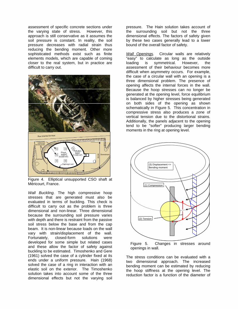
but 0.5% can be commonly achieved in practice. Regardless of the vertical tolerance achieved, the actual geometry will not be a perfect ring. The common approach used to take into account the "real" geometry is to inscribe an annulus into the actual shape and calculate the wall loads neglecting the concrete outside this annulus. This method is very conservative because an inscribed annulus is not a necessary condition for stability because the wall is capable of resisting bending and shear stresses. This is easily demonstrated by considering self stable elliptical shafts wherein an inscribed circle is not possible. An example is shown in Figure 4 of the Méricourt CSO shaft. Wall Shape. With elliptical shafts the external soil provides the required extra reaction to maintain stability. The wall sections experience varying bending moments with location in addition to the compressive stresses because the radial strains/displacements are no longer uniform. The stresses resulting from the actual geometry are evaluated by modelling the wall as a horizontal beam in interaction with an elastic plastic soil on one side only. This model gives the normal forces, N, and the bending moments, M, at each node. This model allows for the
P1
P2P3
P4
P5 P8
P7P6
Φint = 16m
L = 2.8m
e = 0.5m
P1
P2P3
P4
P5 P8
P7P6
Φint = 16m
L = 2.8m
e = 0.5m
Figure 3 : Shape of a circular diaphragm wall including (la) grab geometry without deviation and (b) grab geometry and deviation.
(a) (b)
assessment of specific concrete sections under the varying state of stress. However, this approach is still conservative as it assumes the soil pressure is constant. In reality, the soil pressure decreases with radial strain thus reducing the bending moment. Other more sophisticated methods exist such as finite elements models, which are capable of coming closer to the real system, but in practice are difficult to carry out.
Figure 4. Elliptical unsupported CSO shaft at Méricourt, France. Wall Buckling. The high compressive hoop stresses that are generated must also be evaluated in terms of buckling. This check is difficult to carry out as the problem is three dimensional and non-linear. Three dimensional because the surrounding soil pressure varies with depth and there is restraint from the passive soil stress below the base and from the cap beam. It is non-linear because loads on the wall vary with strain/displacement of the wall. Fortunately, closed-form solutions were developed for some simple but related cases and these allow the factor of safety against buckling to be estimated. Timoshenko and Gere (1961) solved the case of a cylinder fixed at its ends under a uniform pressure. Hain (1968) solved the case of a ring in interaction with an elastic soil on the exterior. The Timoshenko solution takes into account some of the three dimensional effects but not the varying soil
pressure. The Hain solution takes account of the surrounding soil but not the three dimensional effects. The factors of safety given by these two cases generally lead to a lower bound of the overall factor of safety. Wall Openings. Circular walls are relatively “easy” to calculate as long as the outside loading is symmetrical. However, the assessment of their behaviour becomes more difficult when asymmetry occurs. For example, the case of a circular wall with an opening is a three dimensional problem. The presence of opening affects the internal forces in the wall. Because the hoop stresses can no longer be generated at the opening level, force equilibrium is balanced by higher stresses being generated on both sides of the opening as shown schematically in Figure 5. This concentration in compressive stress also produces a zone of vertical tension due to the distortional strains. Additionally, the panels adjacent to the opening tend to be "softer" producing larger bending moments in the ring at opening level.
The stress conditions can be evaluated with a two dimensional approach. The increased bending moment can be estimated by reducing the hoop stiffness at the opening level. The reduction factor is a function of the diameter of
(3) Displacement => Bending moment
(2) Tension
(1) Compression
(3) Displacement => Bending moment
(2) Tension
(1) Compression
Figure 5. Changes in stresses around openings in wall.
the wall, the diameter of the opening and the curvilinear abscissa. The tension stress and the concentration of hoop stress is estimated with a plane plate calculation Producing Other Shaped Walls with Circular Arcs Alternatives to rectangular walls can often be constructed with circular arc segments thereby reducing or eliminating the need for anchorage or bracing. Unsupported elliptical shafts (Figure 4) require relatively small a / b ratio where a and b represent the long and the short axis, respectively. Another restriction is that the surrounding ground must be stiff. As the water and active earth pressures are approximately the same around the shaft, the hoop force must be greater along the long side than along the short side. In order to balance all the forces, the wall has to mobilize a strong soil reaction along the short side and this reaction is mobilized through wall displacement. In order to maintain wall stability these induced displacements must be small enough so as not to generate excessive bending moment. When the shapes of the wall components deviate from continuous arcs, "flying" beams, abutment, or counterfort walls can be build to support the hoop forces. These combined systems have been successfully built in Europe, Asia and South America. The advantages of this kind of approach include the use of thinner
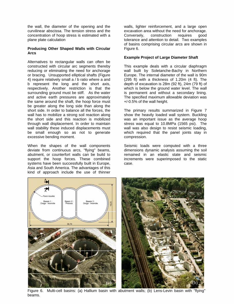
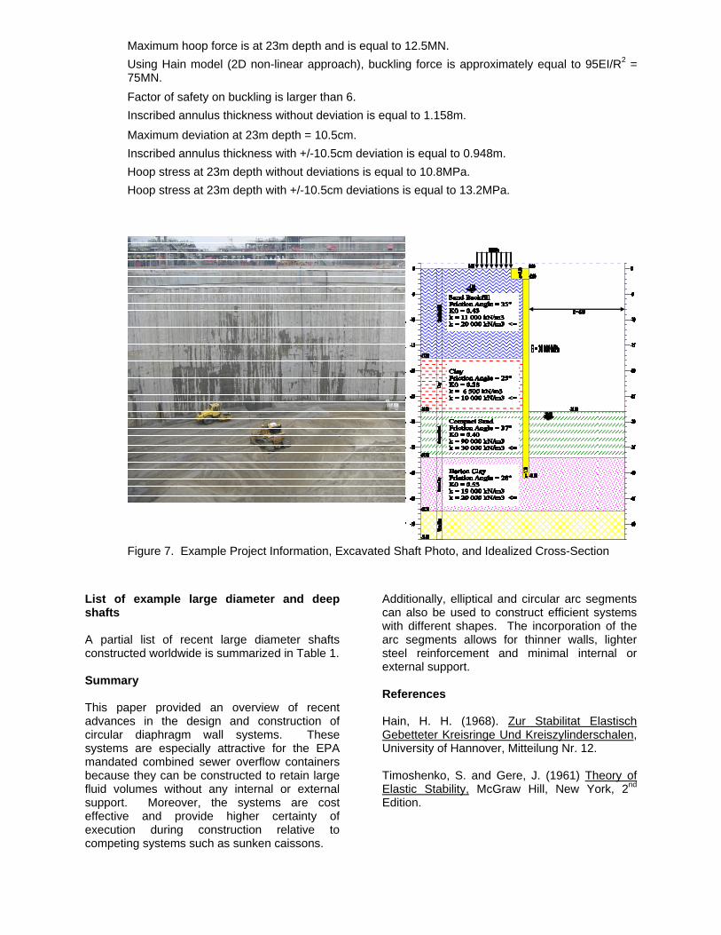
walls, lighter reinforcement, and a large open excavation area without the need for anchorage. Conversely, construction requires good tolerance and attention to detail. Two examples of basins comprising circular arcs are shown in Figure 6. Example Project of Large Diameter Shaft This example deals with a circular diaphragm wall built by Soletanche-Bachy in Northern Europe. The internal diameter of the wall is 90m (295 ft) with a thickness of 1.20m (4 ft). The depth of excavation is 28m (92 ft), 24m (79 ft) of which is below the ground water level. The wall is permanent and without a secondary lining. The specified maximum allowable deviation was +/-0.5% of the wall height. The primary results summarized in Figure 7 show the heavily loaded wall system. Buckling was an important issue as the average hoop stress was equal to 10.8MPa (1565 psi). The wall was also design to resist seismic loading, which required that the panel joints stay in compression. Seismic loads were computed with a three dimensions dynamic analysis assuming the soil remained in an elastic state and seismic increments were superimposed to the static case.
Figure 6. Multi-cell basins: (a) Hallium basin with abutment walls; (b) Lens-Levin basin with "flying" beams.
(a) (b)
List of example large diameter and deep shafts A partial list of recent large diameter shafts constructed worldwide is summarized in Table 1. Summary This paper provided an overview of recent advances in the design and construction of circular diaphragm wall systems. These systems are especially attractive for the EPA mandated combined sewer overflow containers because they can be constructed to retain large fluid volumes without any internal or external support. Moreover, the systems are cost effective and provide higher certainty of execution during construction relative to competing systems such as sunken caissons.
Additionally, elliptical and circular arc segments can also be used to construct efficient systems with different shapes. The incorporation of the arc segments allows for thinner walls, lighter steel reinforcement and minimal internal or external support. References Hain, H. H. (1968). Zur Stabilitat Elastisch Gebetteter Kreisringe Und Kreiszylinderschalen, University of Hannover, Mitteilung Nr. 12. Timoshenko, S. and Gere, J. (1961) Theory of Elastic Stability, McGraw Hill, New York, 2nd Edition.
Maximum hoop force is at 23m depth and is equal to 12.5MN. Using Hain model (2D non-linear approach), buckling force is approximately equal to 95EI/R2 = 75MN. Factor of safety on buckling is larger than 6. Inscribed annulus thickness without deviation is equal to 1.158m.
Maximum deviation at 23m depth = 10.5cm. Inscribed annulus thickness with +/-10.5cm deviation is equal to 0.948m. Hoop stress at 23m depth without deviations is equal to 10.8MPa. Hoop stress at 23m depth with +/-10.5cm deviations is equal to 13.2MPa.
Figure 7. Example Project Information, Excavated Shaft Photo, and Idealized Cross-Section
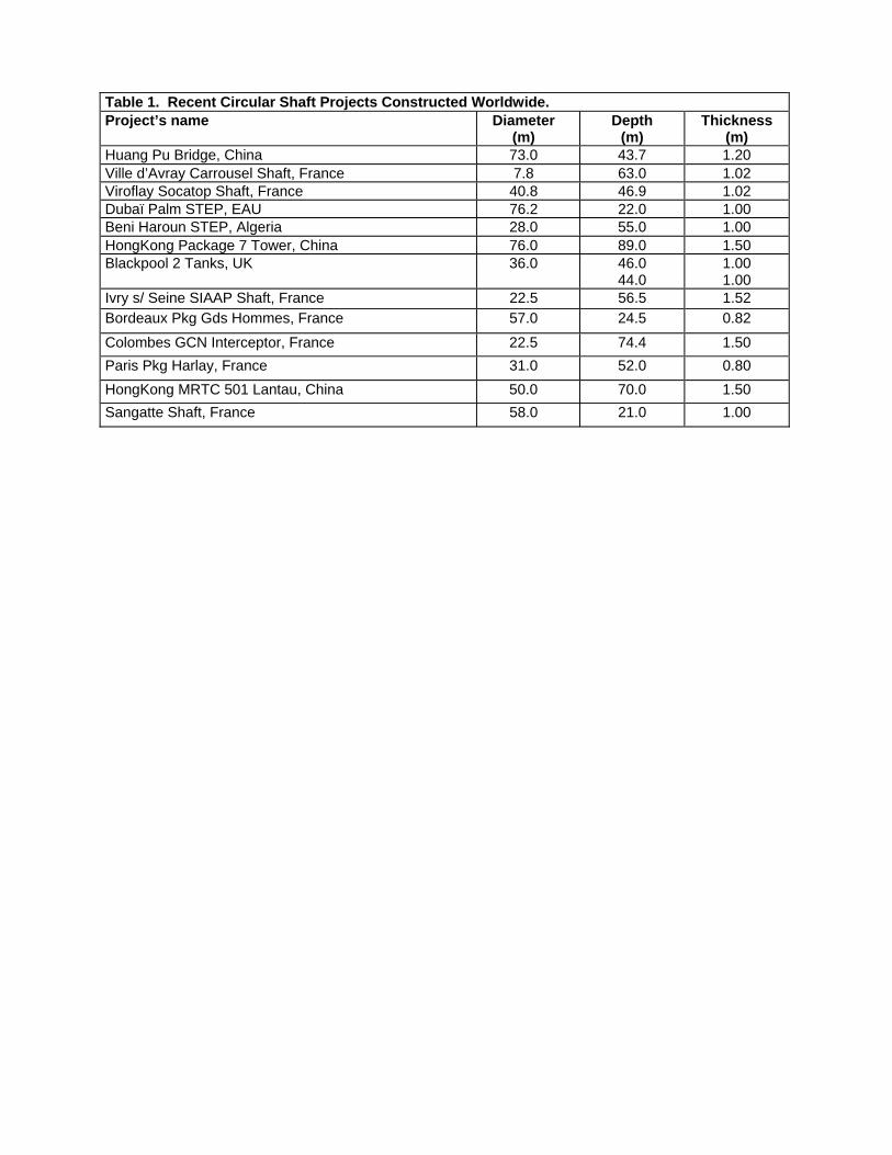
Table 1. Recent Circular Shaft Projects Constructed Worldwide. Project’s name Diameter
(m) Depth
(m) Thickness
(m) Huang Pu Bridge, China 73.0 43.7 1.20 Ville d’Avray Carrousel Shaft, France 7.8 63.0 1.02 Viroflay Socatop Shaft, France 40.8 46.9 1.02 Dubaï Palm STEP, EAU 76.2 22.0 1.00 Beni Haroun STEP, Algeria 28.0 55.0 1.00 HongKong Package 7 Tower, China 76.0 89.0 1.50 Blackpool 2 Tanks, UK 36.0
46.0 44.0
1.00 1.00
Ivry s/ Seine SIAAP Shaft, France 22.5 56.5 1.52 Bordeaux Pkg Gds Hommes, France 57.0 24.5 0.82
Colombes GCN Interceptor, France 22.5 74.4 1.50 Paris Pkg Harlay, France 31.0 52.0 0.80 HongKong MRTC 501 Lantau, China 50.0 70.0 1.50 Sangatte Shaft, France 58.0 21.0 1.00