lake mead marvel - lane construct mead marvel... · along the lake mead shore; ... such a...
TRANSCRIPT
o c t o b e r 2 0 1 6 C i v i l E n g i n e e r i n g [59]
PH
OT
OC
RE
DIT
GO
ES
HE
RE
As the drought in the western United
States lowered water levels at Lake Mead,
the Southern Nevada Water Authority
fought back by constructing the world’s
deepest subaqueous tunnel. The 3 mi long
concrete-lined tunnel is designed to draw
drinking water from an intake structure
half buried at the bottom of the lake.
By Robert L. Reid
Severe and persistent drought condi-tions over the past 16 years have dropped the water level in Lake Mead, the largest reservoir in the United States, by more than 140 ft. The response by the Southern Nevada Water Authority (snwa), a nonprofit cooperative government utility that was formed in 1991 to address southern Nevada’s water needs on
a regional basis, has included extensive conservation efforts that helped reduce per capita water use in the Las Vegas Val-ley by more than 40 percent between 2002 and 2014, even as the population there increased by more than 500,000, the snwa reports on its website.
But with the reservoir’s surface water level falling recent-ly to just under 1,075 ft above mean sea level—its lowest level since the completion in 1936 of Hoover Dam, which
[58] C i v i l E n g i n e e r i n g o c t o b e r 2 0 1 6 0885-7024/14-0009-00??/$30.00 PER ARTICLE
PH
OT
OC
RE
DIT
GO
ES
HE
RE
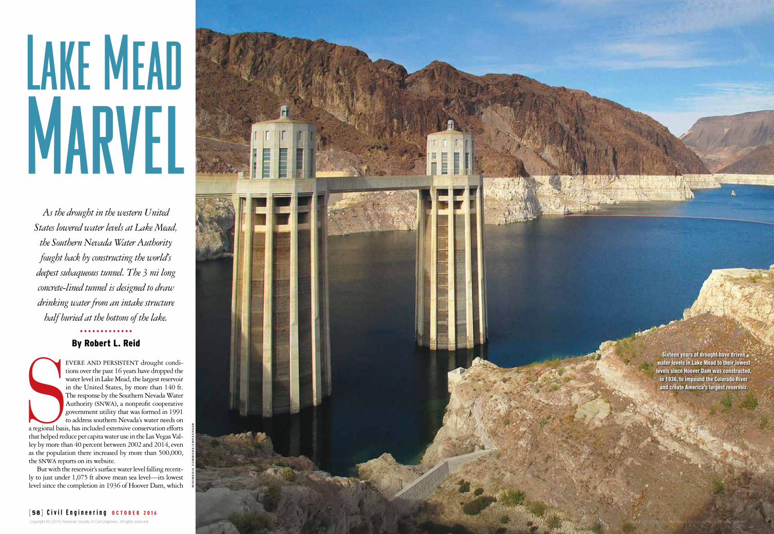
Sixteen years of drought have driven water levels in Lake Mead to their lowest levels since Hoover Dam was constructed,
in 1936, to impound the Colorado River and create America’s largest reservoir.
Lake MeadMarvel
WIK
IME
DIA
CO
MM
ON
S/C
MP
XC
HG
8B
Copyright © 2016 American Society of Civil Engineers. All rights reserved. Copyright © 2016 American Society of Civil Engineers. All rights reserved.
o c t o b e r 2 0 1 6 C i v i l E n g i n e e r i n g [61] [60] C i v i l E n g i n e e r i n g o c t o b e r 2 0 1 6 0885-7024/16-0010-0058/$30.00 PER ARTICLE
SO
UT
HE
RN
NE
VA
DA
WA
TE
R A
UT
HO
RIT
Y,
BO
TH
of the international engineering firm Arup, which served as the engineer of record and led the engineering design of the design/build project.
Arup worked directly for the design/build contractor, Ve-gas Tunnel Constructors, llc, a joint venture of S.A. Healy Company, of Henderson, Nevada, and Salini Impregilo S.p.A., of Milano, Italy. Parsons, headquartered in Pasadena, California, provided program management and construction management services. A joint venture of mwh Global, Inc., of Broomfield, Colorado, and ch2m, of Englewood, Colora-do, served as the owner’s engineers.
Arup’s work on the third intake project included structur-al, geotechnical, highway, maritime, water engineering, and site supervision services. In particular, the firm was responsi-ble for the design of the third intake itself, a mostly concrete-framed structure that is half buried beneath the lake bed at an elevation of 860 ft; a 600 ft deep access shaft constructed along the Lake Mead shore; and a 3 mi long tunnel that is 20 ft in diameter and links the base of the access shaft with the base of the intake structure, providing the route through which the water flows. Excavated beneath the lake bed via a tunnel-boring machine (tbm), the concrete-lined third in-take tunnel was constructed under record-setting water pres-sures of up to 15 bars, Hurt says.
Denver-based Brierley Associates assisted Arup with the geotechnical investigations and certain aspects of the ac-cess shaft design. The mwh Global/ch2m joint venture also performed preconstruction geotechnical inspec-tions and work on the development of the design criteria contained in the project’s request for proposals.
The shaft was constructed on a ridge of land known as Saddle Island. Once an actual island connected to the shore by a causeway, Hurt says, Saddle Island is now more of a pen-insula because the falling water lev-els of Lake Mead have exposed land around the site that used to be sub-merged. The shaft site was relatively open, undeveloped land on a hillside that was partially excavated to cre-ate a level work zone, Hurt adds. A two-lane paved access road also had
to be designed and constructed to reach the site, including a new turning lane that was added to an existing highway that winds its way through the Lake Mead National Recreation Area, which surrounds the project site.
As part of a separate project, a bicycle lane was under con-struction along the roughly half-mile route of the access road, and to allow the trucks and other vehicles for the intake proj-ect to pass over the new bike lane, a precast-concrete bridge also was constructed at the site, Hurt says. Because the area can be home to the desert tortoise, an endangered species, the site was investigated to ensure that no tortoises were present, and special fencing was then installed along the perimeter to prevent any tortoises from entering the site later, Hurt adds.
The shaft itself is 30 ft in diameter and lined with 18 in. thick concrete walls. Constructed via the drill and blast method, the shaft was initially designed to provide access for the tbm, a 600 ft long, 23.5 ft diameter hybrid device manufactured by Herrenknecht ag, of Schwanau, Germa-ny. The shaft was constructed within relatively challenging soil conditions that featured highly fractured rock, a detach-ment fault and shear zones, a high water table, and rock per-
meability that was worse than expect-ed, notes Hurt. The areas of broken rock were especially difficult because of the extreme depths of the excavation and the fact that the water could flow through
impounds Colorado River water in Lake Mead, according to a May 22 cbs News on-line report, “Lake Mead Hits All-Time Low Amidst Ongoing Drought”—the region has faced potentially severe regulatory and tech-nical challenges. On the regulatory side, at a sustained water level below 1,075 ft, the U.S. secretary of the interior could declare an official “shortage,” which could trigger reductions in the region’s water alloca-tions. Such a declaration would not have an immediate effect on the region because the success of the aforementioned con-servation efforts means that southern Nevada does not cur-rently use its full water allocation, the snwa notes. Eventual-ly, however, the region could see its Colorado River allocation drop from 300,000 acre-ft per year to 287,000 acre-ft.
A more imminent danger is that if the water level falls as low as 1,050 ft, one of the snwa’s two original drinking wa-ter intakes and its associated pumping station will be physi-cally incapable of drawing any more water from the lake. At a level of 1,000 ft, the second of the original intakes and its pumping station also would become inoperable.
It was to avoid that sort of dry doomsday scenario that in 2008 the snwa began construction work on a major engi-neering project that became operational in September 2015 and was considered complete that December: a prefabricated third intake structure and a 3 mi long tunnel designed, in conjunction with a planned new pumping station, to be able to draw water even at a depth as low as 860 ft above mean sea level. This is near the bottom of the lake and well below the 897 ft level, known as the dead pool, at which Hoover Dam itself would no longer be able to release water, explains Erika Moonin, p.e., d.wre, m.asce, the snwa’s engineer-ing project manager. Now that the third intake is operation-al, the snwa has closed the first and second intakes and is
relying solely on the new intake because it can draw water of better quality from those deeper levels, notes Moonin. At the moment, the third intake system is using the pump-ing stations of both the first and the second intake, which means that even the third in-take would become inoperable if the water
level were to fall to 1,000 ft. However, once the new “low lake level” pumping station is completed, roughly in 2020, the snwa will be able to pump water from deep within the lake, well below that 1,000 ft threshold, ensuring the water supply for southern Nevada, Moonin says.
The nearly $800-million project to construct Intake No. 3 was named one of six finalists in the competition for asce’s 2016 Outstanding Civil Engineering Achievement Award. Although the award ultimately went to the Dragon Bridge, in Da Nang, Vietnam, asce acknowledged the “complex rock conditions” encountered at Lake Mead in constructing the world’s deepest subaqueous tunnel and praised the design team for its “innovative approach of installing a prefabricat-ed intake structure under the lake bed using immersed tube techniques to mitigate the risks inherent in construction un-der 300 ft of water.”
The third intake was designed not only to protect the snwa’s access to drinking water for the Las Vegas Valley area but also to maintain water quality standards, which can deteriorate as drought-related decreases in water levels, flows, and volumes lead to increased salinity, algal blooms, and other problems. But while the collection of water closer to the bottom of Lake Mead will help to address the quality concerns, the actual construction and installation of the infra-structure for the third intake presented an array of complex and formidable engineering challenges, explains Jon Hurt, p.e., CEng, m.asce, a principal in the New York City office
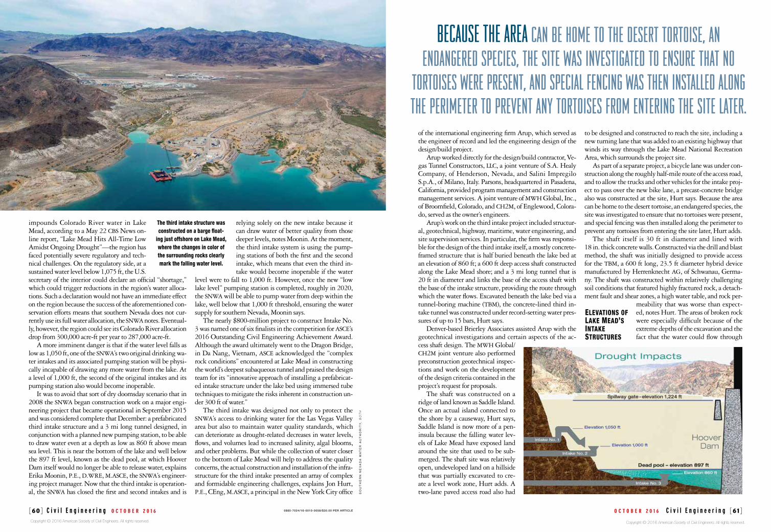
ElEvations of lakE MEad’s intakE structurEs
The third intake structure was constructed on a barge float-
ing just offshore on Lake Mead, where the changes in color of the surrounding rocks clearly mark the falling water level.
BECAUSE THE AREA can be home to the desert tortoise, an endangered species, the site was investigated to ensure that no
tortoises were present, and special fencing was then installed along the perimeter to prevent any tortoises from entering the site later.
Copyright © 2016 American Society of Civil Engineers. All rights reserved. Copyright © 2016 American Society of Civil Engineers. All rights reserved.
o c t o b e r 2 0 1 6 C i v i l E n g i n e e r i n g [63] [62] C i v i l E n g i n e e r i n g o c t o b e r 2 0 1 6 0885-7024/14-0009-00??/$30.00 PER ARTICLE
SO
UT
HE
RN
NE
VA
DA
WA
TE
R A
UT
HO
RIT
Y,
BO
TH
weighing more than 32 tons and lowered un-derground in segments, were assembled and installed behind the tbm as the machine dug its way forward. The fully shielded hybrid device was designed to operate in two modes: the “open” mode when cutting through hard rock and the “closed” mode when encounter-ing unstable soils and high water pressures. Although the proverbial shortest distance between two points is a straight line, the third intake tunnel instead followed a path curved in plan to avoid areas of broken volcanic rock that had been detected, Hurt notes.
Even then, the original orientation had to be altered when the discovery of an unexpected fault zone near the base of the third intake access shaft led to three instances of inflows of loose, fine material and water—essentially, underground land-slides—that reburied areas that had already been excavated, says Moonin. After conducting additional geotechnical inves-tigations and considering various options, the project team de-cided to realign the tunnel orientation by 23 degrees “to skirt around this bad pocket of ground,” Moonin says.
As a result of the realignment, the tunnel ended up pass-ing primarily through sedimentary rock of lower permea-bility, as well as some basalt closer to the intake itself. With the exception of certain key areas, there is at least 100 ft of rock above the top of the tunnel structure along the route, Hurt says. One is at the base of the intake structure, which
is buried roughly 50 ft beneath the lake bed. The tunnel slopes up from the base of the third intake access shaft to the intake struc-ture by a gradient that ranges from 0.1 per-cent to as much as 3 percent, explained Hurt and his coauthors in their 2010 paper. The steeper gradient commences after the tunnel passes beneath what before the creation of Lake Mead was part of a river channel known as the Las Vegas Wash. Here, there is only
about 25 ft of rock between the bottom of the wash channel and the top of the third intake tunnel, making it the shallow-est portion of soil above the alignment, Hurt notes.
The intake structure was installed in March 2012 prior to the completion of the tunneling phase. Roughly 100 ft tall and weighing 1,400 tons, the intake structure was mostly framed in heavy concrete sections with a stainless steel intake riser 16 ft in diameter. A hexagonal section of the concrete wall at the base reinforced with fiberglass rebar rather than steel so that it would be easier to break through formed the “soft eye”—the connection point for the tunnel and thus the tbm’s target.
To facilitate its delivery to the designated site out on the lake, the intake was constructed on a barge made from modu-lar pontoons floating just offshore. The intake was suspended via a strand jack system above an opening in the barge deck and gradually lowered into the water as each section was con-structed, explained McDonald and two of his Vegas Tunnel Constructors colleagues, Jim Nickerson and James Grayson,
the joints of the broken rock and thus impose the full 15 bars of hydrostatic pressure on the equipment and infrastructure, Hurt says.
An extensive program of preexcavation grouting was re-quired to prevent water ingress during the drilling and blast-ing of the shaft, which essentially involved pumping in a ce-mentitious mixture “to fill up any cracks in the rock ahead of us where the water could flow through,” Hurt explains. The grouting produced a roughly 3 m thick, 36 m deep curtain around the shaft, Hurt noted in the paper “Lake Mead Intake No. 3,” which he coauthored with Moonin and Jim McDon-ald, a Vegas Tunnel Constructors project director. The paper was presented at the 2010 World Tunnel Congress, held in Vancouver, British Columbia.
At the base of the shaft, a cavern nearly 200 ft long, al-most 50 ft wide, and 34 ft tall was constructed to provide the space for launching and operating the tbm. The cavern was supported via a system of fiberglass rock bolts and shotcrete reinforced with steel fibers, explained Hurt and his coauthors in their World Tunnel Con-gress paper. The project experienced serious delays, however, as a result of seepage prob-lems in a starter tunnel for the tbm that was constructed adjacent to the cavern (see “Seep-age Problems Plague Construction of Lake Mead’s Third Intake Project,” by Jay Landers, Civil Engineering, April 2011, pages 28–30).
The seepage issue resulted in a $40-million change order and a roughly 600-day extension of the project deadline.
With the tunneling phase long completed and the tunnel itself carrying lake water, the shaft now serves as a conduit for that water via a smaller “stub” tunnel that is attached to the third intake access shaft at a point roughly 200 ft up from the shaft base, Hurt says. The stub tunnel provides a link to an-other tunnel, known as the connector tunnel, that was con-structed to take the water that comes from the third intake and convey it to the snwa’s existing treatment facilities via the two existing pumping stations. The connector tunnel and a separate access shaft were designed by the mwh Global/ch2m joint venture.
The snwa operates two state-of-the art treatment plants: the Alfred Merritt Smith Water Treatment Facility, which uses ozone, filtration, and chlorine gas processes to treat 600 mgd of drinking water; and the River Mountains Water Treatment Facility, which uses ozonation and sodium hypochlorite to treat
300 mgd, although it is capable of being ex-panded to eventually treat 600 mgd.
The upper portions of the third intake system access shaft and the connector tun-nel access shaft now serve as additional surge relief.
To line and reinforce the tunnel ex-cavation along its 3 mi length under the lake bed, some 2,429 concrete rings, each
A starter tunnel and a cavern were constructed to provide the space for launching the
tunnel-boring machine. Seepage problems in the starter tunnel
resulted in a $40-million change order and a roughly 600-day
extension of the project deadline.
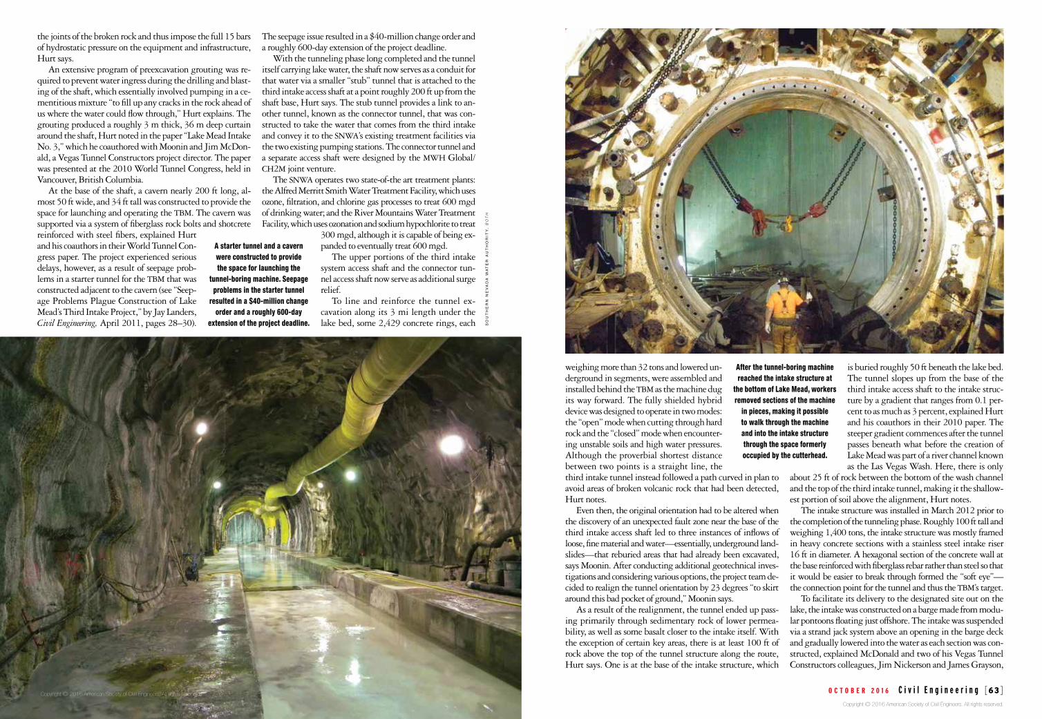
After the tunnel-boring machine reached the intake structure at
the bottom of Lake Mead, workers removed sections of the machine
in pieces, making it possible to walk through the machine and into the intake structure through the space formerly occupied by the cutterhead.
Copyright © 2016 American Society of Civil Engineers. All rights reserved.
Copyright © 2016 American Society of Civil Engineers. All rights reserved.
o c t o b e r 2 0 1 6 C i v i l E n g i n e e r i n g [65] [64] C i v i l E n g i n e e r i n g o c t o b e r 2 0 1 6 0885-7024/14-0009-00??/$30.00 PER ARTICLE
SO
UT
HE
RN
NE
VA
DA
WA
TE
R A
UT
HO
RIT
Y,
BO
TH
the intake structure were being readied for operation, the snwa also broke ground on the low lake level pumping station, which will ensure the third intake’s ability to con-tinue to draw water from heretofore unreach-able depths. The $650-million project will involve the construction of a 26 ft diameter access shaft 528 ft deep. At its bottom, a near-ly 400 ft long horseshoe-shaped cavern 33 ft wide and 36 ft high known as a forebay will be constructed. The forebay will connect to 34 additional vertical shafts that will each be 8 ft in diameter, 500 ft deep, and installed under strict tolerances. These shafts will accommodate the pumping station’s high-lift, high-capacity sub-mersible pumps so that the water can be sent to the snwa’s existing treatment facilities. The authority is currently evaluating different types of equipment from three manufacturers that will combine exist-ing motor and pump technologies in unprecedented ways, Moonin says. The mwh Global/ch2m joint venture designed the new pumping station infra-structure, which is being constructed by Barnard of Nevada, Inc., based in Boulder City, Nevada, as the construction man-ager at risk.
The origins of the third intake and the low lake level pumping plant date to 2002, when the primary concern was water quality, Moonin notes. But by 2005, as the region’s drought continued, the project had evolved into an effort to ensure access to the water supply as well. Now, more than a dozen years after the first steps in this effort were taken, there are few signs of long-term improvement for the Colorado River system, Moonin adds. But because the snwa recog-nized the problem early on and all the players, from the engi-
neers to the tunnel workers, were committed to the cooperative partnership that helped the project succeed, the new intake and its supporting infrastructure will “ensure the water supply for our community,” Moonin concludes.
Thus, thanks to an investment of roughly $1.4 billion and the literally groundbreaking
efforts of all involved, the region can look forward to enjoying a long—and very deep—drink of cool, clean water well into the future. CE
Robert L. Reid is the senior editor of Civil Engineering.
PROJECT CREDITS Owner: Southern Nevada Water Authority, Las Vegas Program manager and construction manager: Parsons, Pasadena, Cali-fornia Owner’s engineer: Joint venture of mwh Global, Inc., Broomfield, Colorado, and ch2m, Englewood, Colorado Tunnel, shaft, and intake structure design/build contractor: Vegas Tunnel
Constructors, llc, a joint venture of S.A. Healy Company, Henderson, Nevada, and Salini Impregilo S.p.A., Milano, Italy Engineer of record and principal design engineer of the tunnel, shaft, and intake structure: Arup, New York City office Geotechnical and third intake access shaft de-sign consultant: Brierley Associates, Denver Tunnel-boring machine manufacturer: Herrenknecht ag, Schwanau, Ger-many Low lake level pumping station designer: Joint ven-ture of mwh Global, Inc., Broomfield, Colorado, and ch2m, Englewood, Colorado Low lake level pumping station con-struction manager at risk: Barnard of Nevada, Inc., Boul-der City, Nevada
in a paper they presented at the 2013 Rapid Excavation and Tunneling Conference, “Lake Mead Intake No. 3 Tunnel In-take Structure and Tremie Concrete Placement,” published in Rapid Excavation and Tunneling Conference 2013 Proceedings (Englewood, Colorado: Society for Mining, Metallurgy & Ex-ploration, Inc., 2013).
Tugboats later moved the barge and intake structure far-ther out on the lake for installation. The designated site was an underwater pit 159 ft long, 95 ft wide, and 83 ft deep that had been excavated in the lake bed via 23,000 shaped charg-es used to blast away the rock over a two-year construction period, explains a Parsons website describing the project. Because divers could not work safely at the depths involved, remotely operated underwater vehicles were used instead to help guide and carefully position the intake on the lake bot-tom. Assistance was provided by pencil buoys, subsea levels, and a gyroscope that featured built-in accelerometers, says Parsons. A steel guiding frame designed for the intake struc-ture was lowered to the lake bottom prior to the structure’s descent. The frame was formed from heavy steel beams and designed to support the weight of the intake structure and maintain its proper orientation during the installation, the Rapid Excavation and Tunneling Conference paper explained.
To secure the intake structure, a foundation was constructed on the lake bed by pumping self-consolidating tremie concrete down from the lake surface in a continuous operation last-ing 12 days that was designed to produce a solid structure with no joints, notes Moonin. The tbm was going to tunnel right into that
mass of concrete, she explains, “so we wanted to make sure it was a nice solid block.”
Moving the concrete out to the middle of the lake so it could be placed around the intake was itself an amazing sight, as regular concrete mixer trucks drove onto barges. The trucks were secured, as many as eight across, and then floated out to the installation site. A trio of these truck-laden barges moved back and forth across Lake Mead in a continuous cy-cle, making more than 140 trips and delivering more than 12,000 cu yd of concrete to fix the intake structure to the lake bottom, explains the snwa website.
The tunnel and the intake structure were connected in December 2014, an engineering achievement that chal-lenged the limits of tbm technology. To line up a long, thin tunnel with a relatively small predetermined target—the roughly 25 ft wide base of the intake structure—over a dis-tance of 3 mi would have been challenging enough, Hurt notes. But attempting it with more than 300 ft of water pressing down from the surface of the lake made the effort even more dramatic. Yet, even though the engineers had de-signed in sufficient tolerances so that the tbm could have been off the mark by as much as a foot in any direction, when
the actual connection between the tunnel and the intake structure was made the result was within just a centimeter or two of the goal, Hurt says. This precision was possible only because of the dedicated crews and the in-novative ideas of the design/build team as all parties worked together to tackle the chal-lenges, says Moonin.
By the middle of 2015, as the tunnel and
A continuous cycle of barges bearing concrete mixer trucks moved back and forth across Lake Mead over a continuous operation lasting 12 days that delivered more than 12,000 cu yd of concrete to fix the intake structure to the lake bottom.
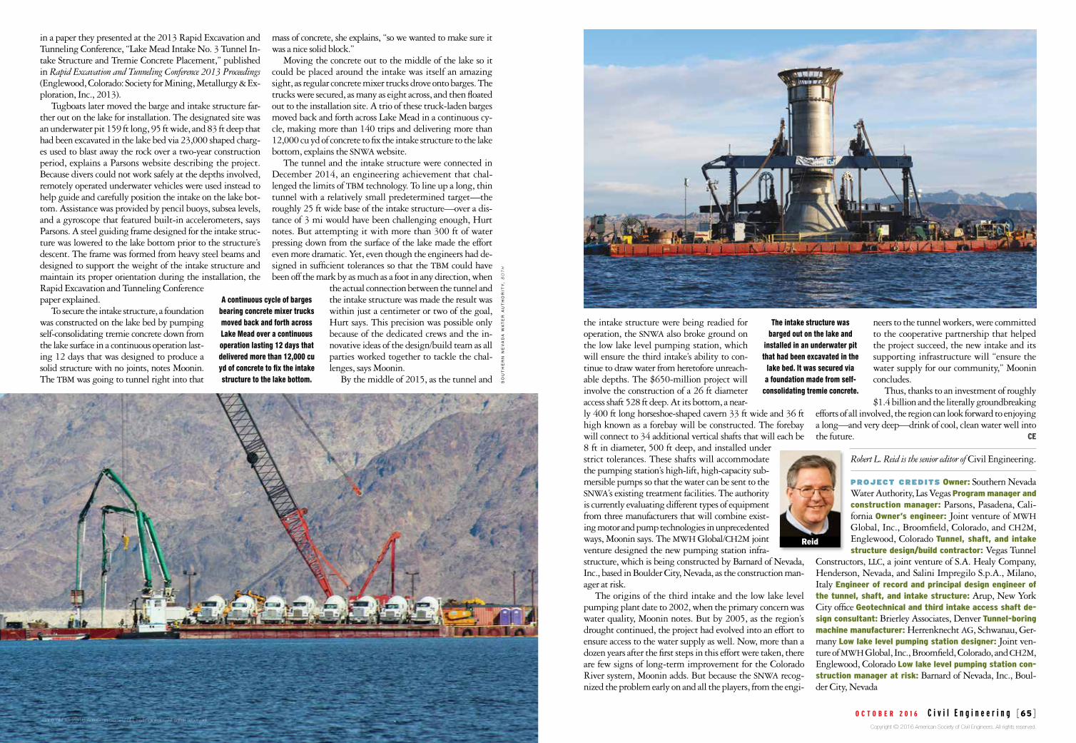
The intake structure was barged out on the lake and
installed in an underwater pit that had been excavated in the
lake bed. It was secured via a foundation made from self-
consolidating tremie concrete.
Reid
Copyright © 2016 American Society of Civil Engineers. All rights reserved. Copyright © 2016 American Society of Civil Engineers. All rights reserved.