labile dissolved organic carbon supply limits hyporheic denitrification · labile dissolved organic...
TRANSCRIPT
Labile dissolved organic carbon supply limitshyporheic denitrification
Jay P. Zarnetske,1,2 Roy Haggerty,3 Steven M. Wondzell,4 and Michelle A. Baker5
Received 4 April 2011; revised 11 October 2011; accepted 22 October 2011; published 31 December 2011.
[1] We used an in situ steady state 15N-labeled nitrate (15NO3�) and acetate (AcO�)
well-to-wells injection experiment to determine how the availability of labile dissolvedorganic carbon (DOC) as AcO� influences microbial denitrification in the hyporheic zoneof an upland (third-order) agricultural stream. The experimental wells receivingconservative (Cl� and Br) and reactive (15NO3
�) solute tracers had hyporheic medianresidence times of 7.0 to 13.1 h, nominal flowpath lengths of 0.7 to 3.7 m, and hypoxicconditions (<1.5 mg O2 L
�1). All receiving wells demonstrated 15N2 production duringambient conditions, indicating that the hyporheic zone was an environment with activedenitrification. The subsequent addition of AcO� stimulated more denitrification asevidenced by significant d15N2 increases by factors of 2.7 to 26.1 in receiving wells andsignificant decreases of NO3
� and DO in the two wells most hydrologically connected to theinjection. The rate of nitrate removal in the hyporheic zone increased from 218 kg ha�1 yr�1
to 521 kg ha�1 yr�1 under elevated AcO� conditions. In all receiving wells, increasesof bromide and 15N2 occurred without concurrent increases in AcO�, indicating that100% of AcO� was retained or lost in the hyporheic zone. These results support thehypothesis that denitrification in anaerobic portions of the hyporheic zone is limited bylabile DOC supply.
Citation: Zarnetske, J. P., R. Haggerty, S. M. Wondzell, and M. A. Baker (2011), Labile dissolved organic carbon supply limitshyporheic denitrification, J. Geophys. Res., 116, G04036, doi:10.1029/2011JG001730.
1. Introduction
[2] There are many environments where denitrificationoccurs, but studies have shown that stream systems are par-ticularly efficient at removing and retaining excess nitrogen(N) [Seitzinger et al., 2006] with headwater and midnetworkstreams being the most effective in regulation of downstreamN exports [Peterson et al., 2001; Alexander et al., 2000;Mulholland et al., 2008]. Characteristic of these headwaterand midnetwork streams is the prominence of stream water–groundwater (hyporheic) exchange flux relative to surfacewater flux [Anderson et al., 2005], especially during periodsof low discharge [Wondzell, 2011]. Hyporheic exchange isalso known to strongly influence N transformations andcycling in streams by increasing solute residence times andsolute contact with reactive biofilms [Duff and Triska, 1990;
Holmes et al., 1994; Jones, 1995; Wondzell and Swanson,1996; Valett et al., 1996; Hedin et al., 1998; Hill et al.,1998]. Therefore, it follows that hyporheic exchange canexert a primary hydrologic control on the export of Nfrom small to midnetwork watersheds.[3] A key factor in the fate of N traveling through a
hyporheic zone (Figure 1) is the organic carbon (C) conditions(substrate quality and quantity) in the stream and hyporheiczone [Baker et al., 1999; Kaplan and Newbold, 2000; Sobczakand Findlay, 2002]. In streams, the predominant form of Cis dissolved organic carbon (DOC) [Fisher and Likens,1973] and only a fraction of that DOC is readily labile(i.e., bioavailable) [Swank and Caskey, 1982]. For hyporheicsystems, either surface or groundwaters enriched with DOCare advected into hyporheic systems and fuel aerobic andanaerobic hyporheic metabolism [Findlay, 1995; Jones,1995; Baker et al., 2000].[4] As reviewed by Duff and Triska [2000, and references
therein], the occurrence of denitrification in the hyporheiczone is complex and is not just related to DOC and NO3
�
availability. Denitrification along hyporheic flowpaths is alsoa function of (1) the concentration of DO across the hyporheiczone which is controlled by biochemical oxygen demand andadvected supply; (2) hyporheic water temperature because itcontrols microbial activity and DO saturation in water; and(3) the hydraulics that drive the physical transport and resi-dence time of water such as the head gradient, hydraulicconductivity, advection, and dispersion. Of these factors,
1Department of Geosciences and Water Resources Graduate Program,Oregon State University, Corvallis, Oregon, USA.
2Now at School of Forestry and Environmental Studies, Yale University,New Haven, Connecticut, USA.
3Department of Geosciences and Institute for Water and Watersheds,Oregon State University, Corvallis, Oregon, USA.
4Pacific Northwest Research Station, Olympia Forestry SciencesLaboratory, Olympia, Washington, USA.
5Department of Biology and the Ecology Center, Utah State University,Logan, Utah, USA.
Copyright 2011 by the American Geophysical Union.0148-0227/11/2011JG001730
JOURNAL OF GEOPHYSICAL RESEARCH, VOL. 116, G04036, doi:10.1029/2011JG001730, 2011
G04036 1 of 13
the biogeochemical conditions controlling hyporheic deni-trification primarily vary by the amount of NO3
� and qualityand quantity of DOC present in the system [Findlay, 1995;Kaplan and Newbold, 2000]. If both NO3
� and labile DOCare abundant then denitrification rates can be large [e.g.,Holmes et al., 1996, Storey et al., 2004]. Spatial patterning ofDOC availability along hyporheic flowpaths adds further tothe complexity. DOC and DO are expected to decline at thehead of the hyporheic flowpaths as microbial processespreferentially utilize DO and labile fractions of DOC [Vervierand Naiman, 1992; Sobczak et al., 2003; Zarnetske et al.,2011]. Further along the hyporheic flowpaths the labile DOCavailability can become depleted leading to DOC qualitylimitations on denitrification [Sobczak et al., 2003; Zarnetskeet al., 2011]. Also, hyporheic DOC sources from stream andgroundwater vary with discharge and season [Vervier andNaiman, 1992; Baker and Vervier, 2004] which, in turn,vary hyporheic metabolism and denitrification.[5] The use of stable isotope (15N) tracers has greatly
advanced understanding of aquatic N cycling by allowing thetracing of N through ecosystem pathways experiencing dif-ferent physical and biological conditions. For example,Böhlke et al. [2004] and Mulholland et al. [2004, 2008]demonstrated the usefulness of the 15N tracer approach forestimating denitrification rates of streams at the reach scale.More recently, subsurface 15N tracing has been successfullyused to study hyporheic processes associated with reactiveN transport [Clilverd et al., 2008; Böhlke et al., 2009;Zarnetske et al., 2011]. Direct hyporheic 15N addition enablesthe distinction between microbial assimilation and retention
pathways and the respiratory denitrification pathway (i.e.,microbial N2 production), which was not possible in previoushyporheic coupled C-N studies that relied on C and N massbalance approaches [e.g., Hedin et al., 1998; Baker et al.,1999; Sobczak et al., 2003]. On the other hand, previousstudies have directly measured hyporheic denitrification (viaacetylene block, N2:Ar ratios, or 15NO3
� additions) acrossspatial and temporal ranges of DOC and NO3
� conditions andfound that a positive correlation exists between the quantityof labile DOC and N2O production [Baker and Vervier, 2004;Smith et al., 2006; Arango et al., 2007; Böhlke et al., 2009].Though the previous studies on coupled hyporheic DOC andN dynamics consistently indicate that the type and quality ofDOC in a hyporheic system influences denitrification rates,none have both isolated the role of labile DOC supply ondenitrification and made direct measurements in a hyporheicenvironment.[6] We evaluate the role of labile DOC on denitrification
along a redox gradient that forms along hyporheic flowpathsin a gravel bar. We combined 15NO3
� tracing techniques withan addition of labile DOC to examine the role of DOC incontrolling denitrification. The previous work at this studysite demonstrated that denitrification and DOC dynamicswere closely coupled [Zarnetske et al., 2011]. Under baseflow conditions, DOC persisted across all residence times,but denitrification rates and DOC uptake decreased beyondthreshold flowpath lengths and residence times (solid curvesin Figure 2). Further, labile DOC was preferentially lost atthe heads of hyporheic flowpaths, leaving the less labilefraction to be transported to more distal portions of the
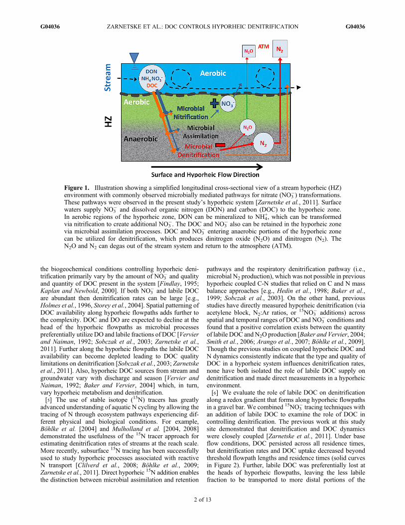
Figure 1. Illustration showing a simplified longitudinal cross-sectional view of a stream hyporheic (HZ)environment with commonly observed microbially mediated pathways for nitrate (NO3
�) transformations.These pathways were observed in the present study’s hyporheic system [Zarnetske et al., 2011]. Surfacewaters supply NO3
� and dissolved organic nitrogen (DON) and carbon (DOC) to the hyporheic zone.In aerobic regions of the hyporheic zone, DON can be mineralized to NH4
+, which can be transformedvia nitrification to create additional NO3
�. The DOC and NO3� also can be retained in the hyporheic zone
via microbial assimilation processes. DOC and NO3� entering anaerobic portions of the hyporheic zone
can be utilized for denitrification, which produces dinitrogen oxide (N2O) and dinitrogen (N2). TheN2O and N2 can degas out of the stream system and return to the atmosphere (ATM).
ZARNETSKE ET AL.: DOC CONTROLS HYPORHEIC DENITRIFICATION G04036G04036
2 of 13
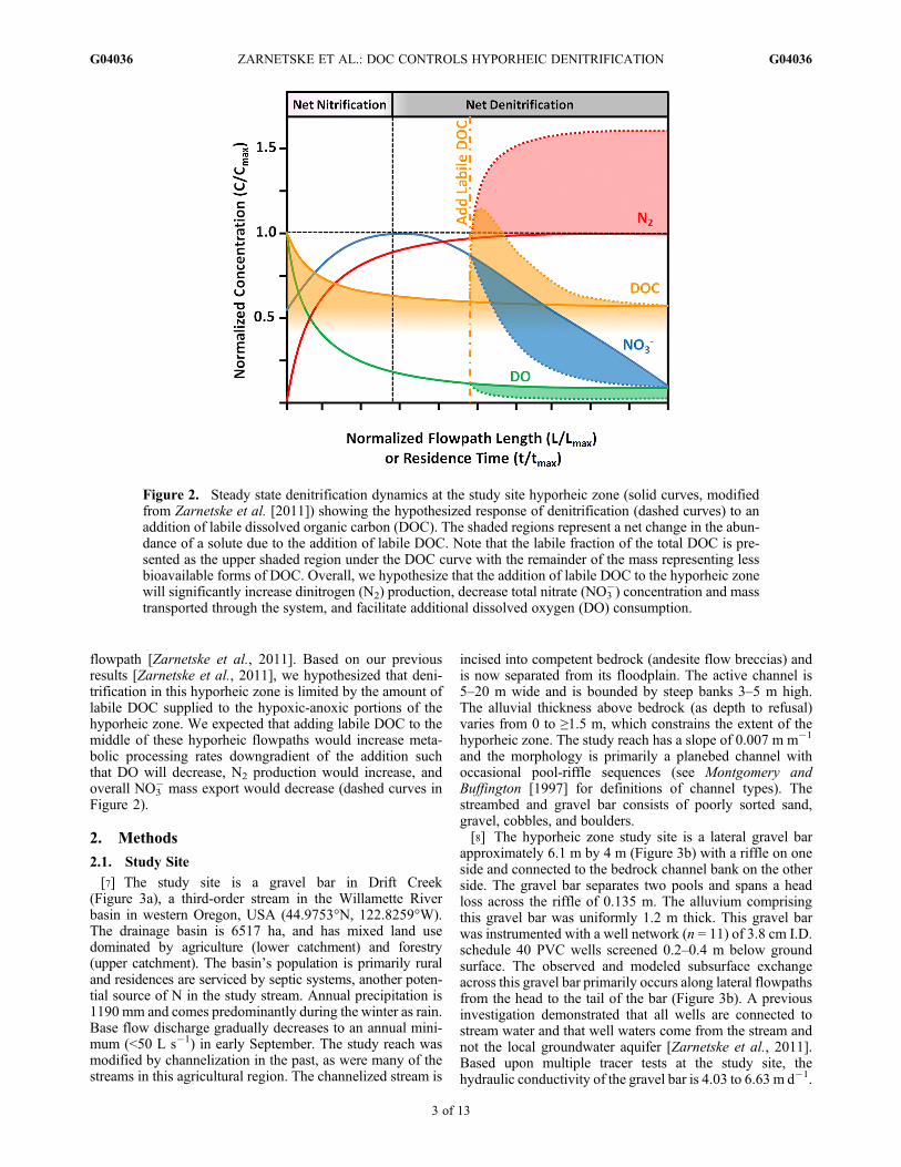
flowpath [Zarnetske et al., 2011]. Based on our previousresults [Zarnetske et al., 2011], we hypothesized that deni-trification in this hyporheic zone is limited by the amount oflabile DOC supplied to the hypoxic-anoxic portions of thehyporheic zone. We expected that adding labile DOC to themiddle of these hyporheic flowpaths would increase meta-bolic processing rates downgradient of the addition suchthat DO will decrease, N2 production would increase, andoverall NO3
� mass export would decrease (dashed curves inFigure 2).
2. Methods
2.1. Study Site
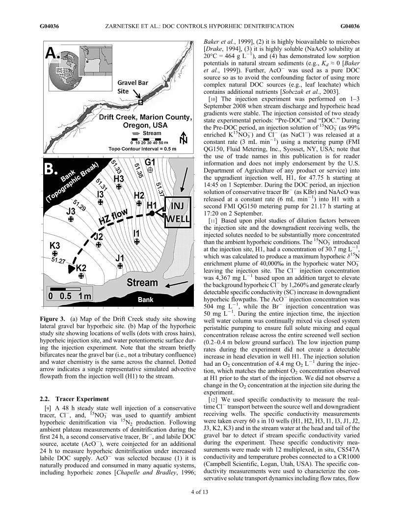
[7] The study site is a gravel bar in Drift Creek(Figure 3a), a third-order stream in the Willamette Riverbasin in western Oregon, USA (44.9753°N, 122.8259°W).The drainage basin is 6517 ha, and has mixed land usedominated by agriculture (lower catchment) and forestry(upper catchment). The basin’s population is primarily ruraland residences are serviced by septic systems, another poten-tial source of N in the study stream. Annual precipitation is1190 mm and comes predominantly during the winter as rain.Base flow discharge gradually decreases to an annual mini-mum (<50 L s�1) in early September. The study reach wasmodified by channelization in the past, as were many of thestreams in this agricultural region. The channelized stream is
incised into competent bedrock (andesite flow breccias) andis now separated from its floodplain. The active channel is5–20 m wide and is bounded by steep banks 3–5 m high.The alluvial thickness above bedrock (as depth to refusal)varies from 0 to ≥1.5 m, which constrains the extent of thehyporheic zone. The study reach has a slope of 0.007 m m�1
and the morphology is primarily a planebed channel withoccasional pool-riffle sequences (see Montgomery andBuffington [1997] for definitions of channel types). Thestreambed and gravel bar consists of poorly sorted sand,gravel, cobbles, and boulders.[8] The hyporheic zone study site is a lateral gravel bar
approximately 6.1 m by 4 m (Figure 3b) with a riffle on oneside and connected to the bedrock channel bank on the otherside. The gravel bar separates two pools and spans a headloss across the riffle of 0.135 m. The alluvium comprisingthis gravel bar was uniformly 1.2 m thick. This gravel barwas instrumented with a well network (n = 11) of 3.8 cm I.D.schedule 40 PVC wells screened 0.2–0.4 m below groundsurface. The observed and modeled subsurface exchangeacross this gravel bar primarily occurs along lateral flowpathsfrom the head to the tail of the bar (Figure 3b). A previousinvestigation demonstrated that all wells are connected tostream water and that well waters come from the stream andnot the local groundwater aquifer [Zarnetske et al., 2011].Based upon multiple tracer tests at the study site, thehydraulic conductivity of the gravel bar is 4.03 to 6.63 m d�1.
Figure 2. Steady state denitrification dynamics at the study site hyporheic zone (solid curves, modifiedfrom Zarnetske et al. [2011]) showing the hypothesized response of denitrification (dashed curves) to anaddition of labile dissolved organic carbon (DOC). The shaded regions represent a net change in the abun-dance of a solute due to the addition of labile DOC. Note that the labile fraction of the total DOC is pre-sented as the upper shaded region under the DOC curve with the remainder of the mass representing lessbioavailable forms of DOC. Overall, we hypothesize that the addition of labile DOC to the hyporheic zonewill significantly increase dinitrogen (N2) production, decrease total nitrate (NO3
�) concentration and masstransported through the system, and facilitate additional dissolved oxygen (DO) consumption.
ZARNETSKE ET AL.: DOC CONTROLS HYPORHEIC DENITRIFICATION G04036G04036
3 of 13
2.2. Tracer Experiment
[9] A 48 h steady state well injection of a conservativetracer, Cl�, and, 15NO3
� was used to quantify ambienthyporheic denitrification via 15N2 production. Followingambient plateau measurements of denitrification during thefirst 24 h, a second conservative tracer, Br�, and labile DOCsource, acetate (AcO�), were coinjected for an additional24 h to measure hyporheic denitrification under increasedlabile DOC supply. AcO� was selected because (1) it isnaturally produced and consumed in many aquatic systems,including hyporheic zones [Chapelle and Bradley, 1996;
Baker et al., 1999], (2) it is highly bioavailable to microbes[Drake, 1994], (3) it is highly soluble (NaAcO solubility at20°C = 464 g L�1), and (4) has demonstrated low sorptionpotentials in natural stream sediments (e.g., Kd ≈ 0 [Bakeret al., 1999]). Further, AcO� was used as a pure DOCsource so as to avoid the confounding factor of using morecomplex natural DOC sources (e.g., leaf leachate) whichcontains additional nutrients [Sobczak et al., 2003].[10] The injection experiment was performed on 1–3
September 2008 when stream discharge and hyporheic headgradients were stable. The injection consisted of two steadystate experimental periods: “Pre-DOC” and “DOC.” Duringthe Pre-DOC period, an injection solution of 15NO3
� (as 99%enriched K15NO3
�) and Cl� (as NaCl�) was released at aconstant rate (3 mL min�1) using a metering pump (FMIQG150, Fluid Metering, Inc., Syosset, NY, USA; note thatthe use of trade names in this publication is for readerinformation and does not imply endorsement by the U.S.Department of Agriculture of any product or service) intothe upgradient injection well, H1, for 47.75 h starting at14:45 on 1 September. During the DOC period, an injectionsolution of conservative tracer Br� (as KBr) and NaAcO wasreleased at a constant rate (6 mL min�1) into H1 with asecond FMI QG150 metering pump for 21.17 h starting at17:20 on 2 September.[11] Based upon pilot studies of dilution factors between
the injection site and the downgradient receiving wells, theinjected solutes needed to be substantially more concentratedthan the ambient hyporheic conditions. The 15NO3
� introducedat the injection site, H1, had a concentration of 30.7 mg L�1,which was calculated to produce a maximum hyporheic d15Nenrichment plume of 40,000‰ in the hyporheic water NO3
�
leaving the injection site. The Cl� injection concentrationwas 4,367 mg L�1 based upon an addition target to elevatethe background hyporheic Cl� by 1,260% and generate clearlydetectable specific conductivity (SC) increase in downgradienthyporheic flowpaths. The AcO� injection concentration was504 mg L�1, while the Br� injection concentration was50 mg L�1. During the entire injection time, the injectionwell water column was continually mixed via closed systemperistaltic pumping to ensure full solute mixing and equalconcentration release across the entire screened well section(0.2–0.4 m below ground surface). The low injection pumprates during the experiment did not create a detectableincrease in head elevation in well H1. The injection solutionhad an O2 concentration of 4.4 mg O2 L
�1 during the injec-tion, which matches the ambient O2 concentration observedat H1 prior to the start of the injection. We did not observe achange in the O2 concentration at the injection site during theexperiment.[12] We used specific conductivity to measure the real-
time Cl� transport between the source well and downgradientreceiving wells. The specific conductivity measurementswere taken every 60 s in 10 wells (H1, H2, H3, I1, I3, J1, J2,J3, K2, K3) and in the stream water at the head and tail of thegravel bar to detect if stream specific conductivity variedduring the experiment. These specific conductivity mea-surements were made with 12 multiplexed, in situ, CS547Aconductivity and temperature probes connected to a CR1000(Campbell Scientific, Logan, Utah, USA). The specific con-ductivity measurements were used to characterize the con-servative solute transport dynamics including flow rates, flow
Figure 3. (a) Map of the Drift Creek study site showinglateral gravel bar hyporheic site. (b) Map of the hyporheicstudy site showing locations of wells (dots with cross hairs),hyporheic injection site, and water potentiometic surface dur-ing the injection experiment. Note that the stream brieflybifurcates near the gravel bar (i.e., not a tributary confluence)and water chemistry is the same across the channel. Dottedarrow indicates a single representative simulated advectiveflowpath from the injection well (H1) to the stream.
ZARNETSKE ET AL.: DOC CONTROLS HYPORHEIC DENITRIFICATION G04036G04036
4 of 13
paths, and residence times as well as to inform the timing ofthe sampling regime described below (for additional detail,see Zarnetske et al. [2011]).[13] The water sampling regime consisted of collecting
multiple rounds of hyporheic samples during the three phasesof the experiment: (1) Preinjections, (2) Pre-DOC plateau(15NO3
� and Cl� steady state), and (3) DOC plateau (AcO�
and Br� steady state). For each location (10 wells plusstream water at the gravel bar head), repeated samplingoccurred during the preinjections (n = 3), Pre-DOC plateau(n = 5), and during DOC amendment (n = 5) periods. ThePre-DOC plateau sampling period was initiated at 18.5 h after15NO3
� and Cl� injection started when all hyporheic wellsdemonstrated steady state specific conductivity values. Fol-lowing the Pre-DOC Cl� transport times, the DOC amend-ment sampling period was initiated at 18.5 h after AcO� andBr� injected started. Repeated hyporheic samples were col-lected approximately every �2 h during each respectiveplateau period. All samples were analyzed for solutes rele-vant to denitrification and tracing injection solutes (d15NO3
�,d15N2, as well as concentrations of NO3
�, AcO�, total DOC,DO, Cl�, and Br�). Hydraulic transport parameters (head,flow rates, flowpaths, and residence times) were alsomeasuredalong the instrumented hyporheic zone.[14] Hyporheic well samples were collected with a field
peristaltic pump (Masterflex L/S, Vernon Hills, Illinois, USA)[Woessner, 2007]. All water samples were immediately fil-tered through ashed Whatman GF/F glass fiber filters (0.7 mmpore size) into acid washed HDPE bottles (60 mL for nutrientchemistry and 1 L for d15N isotope samples). Following fil-tering, nutrient chemistry samples and isotope samples werestored on ice in the field and later refrigerated at 4°C or frozenin the laboratory until processed and analyzed. DO con-centrations were measured in situ with a calibrated YSI DOMeter (Model 52) at all locations prior to collecting eachround of samples. Samples were also collected for d15N2O (g),but could not to be analyzed due to technical problems atthe stable isotope laboratory. Nonetheless, denitrification infreshwater and nearshore marine system sediments consistsalmost entirely of N2 production with N2O/N2 productionratios generally between <0.001 and <0.05 [Seitzinger, 1988;Mulholland et al., 2004], so d15N2 by itself is capable ofcharacterizing the majority of the denitrification dynamics.[15] The d15N gas collection for each sample occurred in
the field and followed procedures adapted from Hamiltonand Ostrom [2007]. A low-flow peristaltic pump was usedto collect 80 mL water samples into a 140 mL plastic syringe(Becton-Dickinson, Franklin Lakes, NJ, USA) fitted withstopcocks. All detectable bubbles were expelled to create azero headspace. Sample syringes were submerged underwater in a processing tub kept at stream temperature to avoidatmospheric N contamination. An underwater transfer of40 mL high-purity He was added to each sample syringe.Equilibration of the N2 (g) into the He headspace of eachsample was achieved by gently agitating the syringes for10 min. After equilibration, 14 mL of headspace gas wasinjected into preevacuated 12 mL exetainers (Labco Ltd.,Wycombe, UK). Preevacuation of exetainers was achievedby pumping them down to a pressure of <50 mTorr usinga Welch vacuum pump (Model DirectTorr 8905, Skokie,Illinois, USA). All exetainers were stored underwater in He
purged DI water-filled centrifuge tubes until sample collec-tion. All sample-filled exetainers were returned to their zeroheadspace He purged DI water-filled centrifuge tubes forstorage until analysis.[16] We conducted a detailed survey of surface water
elevations and channel topography around the instrumentedgravel bar using a Topcon total station (Model GTS-226,Livermore, California, USA) during the tracer experiment.The applied standard surveying methods had a spatial reso-lution of x ≤ 0.1 m, y ≤ 0.1 m, z ≤ 0.005 m for the instru-mented gravel bar.
2.3. Laboratory Procedures
[17] Stream and hyporheic samples were analyzed forNO3
�-N, DOC-C, AcO� (CH3COO�), Cl�, and Br� at the
Oregon State University Institute for Water and WatershedsCollaboratory (Corvallis, USA). The NO3
�-N measurementswere made by a Technicon Auto-Analyzer II using standardcolorimetric methodology with detection limits of 0.001 mgL�1. The concentration of total DOC was determined witha Shimadzu TOC-VCSH Combustion Analyzer (Tokyo,Japan; detection limit = 0.05 mg L�1). The AcO�, Cl�, andBr� were determined by ion chromatography (Dionex 1500,Sunnyvale, California, USA; detection limit = 0.01 mg L�1).[18] The 15N content of the stream and hyporheic water
NO3�was determined by methods adapted from Sigman et al.
[1997] and Mulholland et al. [2004]. These methods arebriefly summarized below. Prior to 15N analysis, 15NO3
�
samples with blanks and standards were processed as follows:(1) A volume of each sample (0.25–1 L; processing volumeis dependent on N content of each sample) was stripped ofits dissolved NH4
+ and had its NO3� concentrated; (2) the
concentrated sample NO3� was captured on a prepared filter
via a reduction/diffusion/sorption procedure (full reductionof NO3
� to NH4+, which is then converted to NH3 that dif-
fuses into the headspace and ultimately gets captured on theacidified sorption filter); and (3) after complete transfer ofNO3
� to the sample filter, the samples were sealed and sentfor 15NO3
� analysis. All 15NO3� and 15N-gas samples were
analyzed by the Marine Biological Laboratory Stable IsotopeFacility (MBL, Woods Hole, Massachusetts, USA). Data arereported using delta notation, where
d15N ¼ 1000� Rsample
Rstandard� 1
� �ð1Þ
and R is the ratio of 15N:14N in the sample or standard(atmospheric gas). Replicate analyses of the water and gassamples show the precision of d15NO3
� and d15N2 isotopemeasurements is �80.0‰ and �0.2‰, respectively.
2.4. Parameter and Statistical Calculations
[19] The specific conductivity breakthrough curves (as ameasure of Cl� transport) were used to calculate the medianresidence time of the hyporheic water flowpaths for alldowngradient wells receiving a detectable specific conduc-tivity increase from the injection site. The median residencetime was calculated as the time required to raise the specificconductivity in the well to one half the plateau specific con-ductivity [Zarnetske et al., 2011]. The nominal flowpath
ZARNETSKE ET AL.: DOC CONTROLS HYPORHEIC DENITRIFICATION G04036G04036
5 of 13
length was measured as linear distance between the injectionsite and each downgradient well [Zarnetske et al., 2011].[20] The connectivity of the receiving wells to the injec-
tion well was based on the conservative tracer (Cl� and Br�)transport during the experiment. The hydrologic connectivity(D) to the injection well at steady state, i.e., the fraction ofwater arriving at the receiving well that originated at theinjection, was calculated as:
Dx;t ¼ Cx;t � Cx;t¼0
Cinj � Cx;t¼0ð2Þ
where c is the concentration of the conservative tracer Cl�, xis the well location, t is the time of sample, and inj is theinjection site. In the absence of biological or chemicalremoval pathways, conservative and reactive tracer transportshould be identical. Based upon this assumption, we used thehydrologic connectivity, D, to calculate the predicted reac-tive solute concentrations for NO3
�, DOC, and AcO� in eachof the receiving wells before and during the AcO� augmen-tation period as:
Spred;x;t ¼ SinjDx;t þ Sx;t¼0 1� Dx;t
� � ð3Þ
where Spred is the predicted concentration of the solute ofinterest at steady state. We then calculated the differencebetween the measured and predicted reactive solute con-centrations for each well during the AcO� augmentationplateau conditions. NO3
�, DOC, and AcO� removal occurswhen the observed concentration is less than the predictedconcentration and production occurs when the observed con-centration is greater than the predicted concentration [Hedinet al., 1998; Baker et al., 1999]. Further, if the differencebetween predicted and observed NO3
� concentration increasesfollowing AcO� augmentation, it indicates increased rates ofNO3
� removal along the hyporheic flowpath when AcO� wasadded to the system.[21] We compared changes in concentrations of solutes for
the Pre-DOC and DOC treatment periods using a paired t test(significance at p = 0.05, df = 4). We treated repeated sampleswithin a well as independent replicates. We ran paired t teststo determine how strongly means of Pre-DOC and means of
DOC differed in each well. We excluded wells H3, I1, I3, J1,and J3 because they did not receive measureable concentra-tions of the added solutes.
3. Results
3.1. Background Stream and HyporheicBiogeochemical Conditions
[22] Streamflow conditions were relatively stable over theexperiment with a mean flow of 32 L s�1 and a variance of�3.2 L s�1. We did not observe any detectable change inhead across the gravel bar during the experiment. Streamand hyporheic water temperature ranged between 12.8 and15.8°C during the injection experiment. Measured streamsurface water nutrient and chemistry conditions were stableduring the experiment with mean and 1 standard deviation(n = 13) values of NO3
� (0.61 � 0.01 mg N L�1), AcO�
(<0.01 � 0.005 mg L�1), DOC (1.94 � 0.36 mg C L�1),DO (10.62 � 0.98 mg O2 L
�1), Cl� (3.60 � 0.25 mg L�1),Br� (0.010 � 0.005 mg L�1) and pH (6.8 � 0.2).[23] Background hyporheic conditions collected imme-
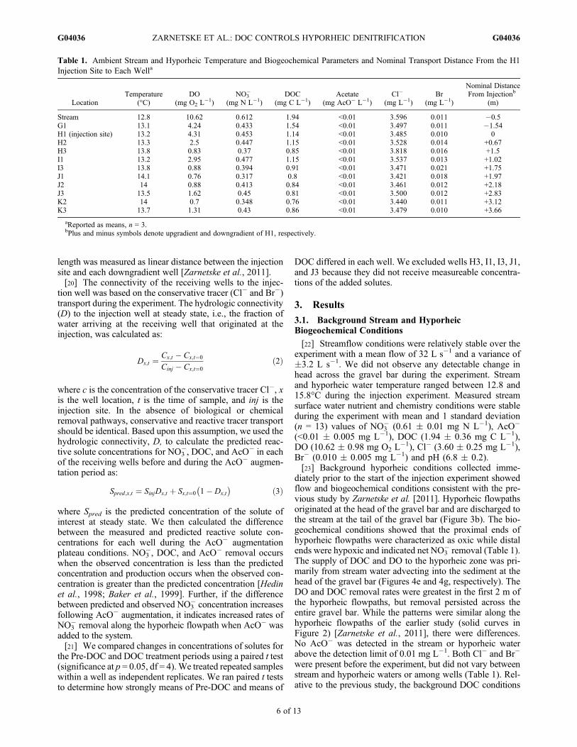
diately prior to the start of the injection experiment showedflow and biogeochemical conditions consistent with the pre-vious study by Zarnetske et al. [2011]. Hyporheic flowpathsoriginated at the head of the gravel bar and are discharged tothe stream at the tail of the gravel bar (Figure 3b). The bio-geochemical conditions showed that the proximal ends ofhyporheic flowpaths were characterized as oxic while distalends were hypoxic and indicated net NO3
� removal (Table 1).The supply of DOC and DO to the hyporheic zone was pri-marily from stream water advecting into the sediment at thehead of the gravel bar (Figures 4e and 4g, respectively). TheDO and DOC removal rates were greatest in the first 2 m ofthe hyporheic flowpaths, but removal persisted across theentire gravel bar. While the patterns were similar along thehyporheic flowpaths of the earlier study (solid curves inFigure 2) [Zarnetske et al., 2011], there were differences.No AcO� was detected in the stream or hyporheic waterabove the detection limit of 0.01 mg L�1. Both Cl� and Br�
were present before the experiment, but did not vary betweenstream and hyporheic waters or among wells (Table 1). Rel-ative to the previous study, the background DOC conditions
Table 1. Ambient Stream and Hyporheic Temperature and Biogeochemical Parameters and Nominal Transport Distance From the H1Injection Site to Each Wella
LocationTemperature
(°C)DO
(mg O2 L�1)
NO3�
(mg N L�1)DOC
(mg C L�1)Acetate
(mg AcO� L�1)Cl�
(mg L�1)Br
(mg L�1)
Nominal DistanceFrom Injectionb
(m)
Stream 12.8 10.62 0.612 1.94 <0.01 3.596 0.011 �0.5G1 13.1 4.24 0.433 1.54 <0.01 3.497 0.011 �1.54H1 (injection site) 13.2 4.31 0.453 1.14 <0.01 3.485 0.010 0H2 13.3 2.5 0.447 1.15 <0.01 3.528 0.014 +0.67H3 13.8 0.83 0.37 0.85 <0.01 3.818 0.016 +1.5I1 13.2 2.95 0.477 1.15 <0.01 3.537 0.013 +1.02I3 13.8 0.88 0.394 0.91 <0.01 3.471 0.021 +1.75J1 14.1 0.76 0.317 0.8 <0.01 3.421 0.018 +1.97J2 14 0.88 0.413 0.84 <0.01 3.461 0.012 +2.18J3 13.5 1.62 0.45 0.81 <0.01 3.500 0.012 +2.83K2 14 0.7 0.348 0.76 <0.01 3.440 0.011 +3.12K3 13.7 1.31 0.43 0.86 <0.01 3.479 0.010 +3.66
aReported as means, n = 3.bPlus and minus symbols denote upgradient and downgradient of H1, respectively.
ZARNETSKE ET AL.: DOC CONTROLS HYPORHEIC DENITRIFICATION G04036G04036
6 of 13
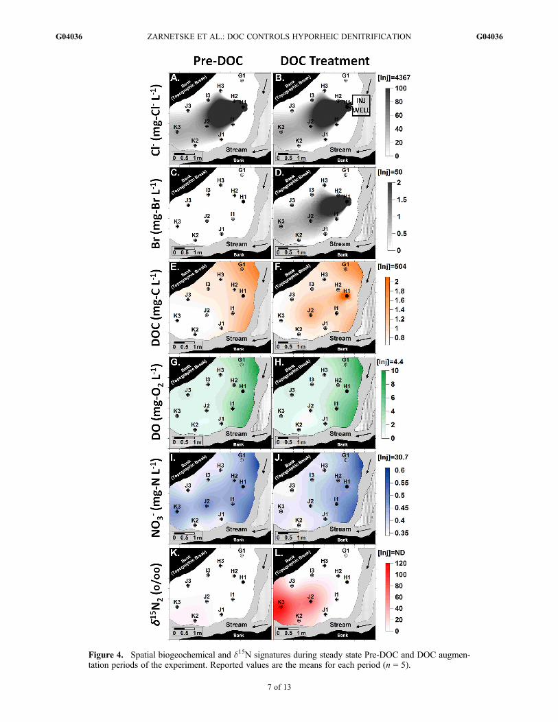
Figure 4. Spatial biogeochemical and d15N signatures during steady state Pre-DOC and DOC augmen-tation periods of the experiment. Reported values are the means for each period (n = 5).
ZARNETSKE ET AL.: DOC CONTROLS HYPORHEIC DENITRIFICATION G04036G04036
7 of 13
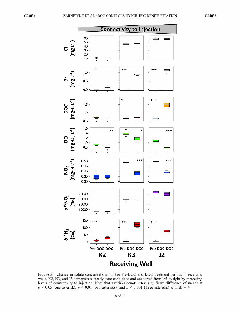
Figure 5. Change in solute concentrations for the Pre-DOC and DOC treatment periods in receivingwells. K2, K3, and J3 demonstrate steady state conditions and are sorted from left to right by increasinglevels of connectivity to injection. Note that asterisks denote t test significant difference of means atp < 0.05 (one asterisk), p < 0.01 (two asterisks), and p < 0.001 (three asterisks) with df = 4.
ZARNETSKE ET AL.: DOC CONTROLS HYPORHEIC DENITRIFICATION G04036G04036
8 of 13

were lower in stream and hyporheic waters and a strongnitrification region at the head of the hyporheic flowpathswas not present.
3.2. Solute Transport and Retention: Pre-DOCAddition
[24] Four of the nine downgradient wells were hydrolog-ically connected to the H1 well injection site as determinedby a significant increase (p < 0.05; t test; df = 4) in Cl�
during the first Pre-DOC injection plateau period (H2, J2,K2, K3; Figures 4 and 5). The steady state hydrologic con-nectivity (D) to the injection was 0.013 at J2, 0.0020 at K2,and 0.0090 at K3 (Table 2). (Note that the tracer injectionrate was very low and was diluted into a large volume ofhyporheic water flowing through the gravel bar. Still, therelatively high concentration of conservative and 15N tracersresulted in distinct breakthroughs, despite the apparent lowconnectivity). The H2 well was connected to the injectionwell, but the level of connectivity varied between Pre-DOCand DOC periods thereby failing the experimental assump-tion of steady state flow dynamics between the experimentalinjection periods as shown in section 3.3. The specific con-ductivity did not vary significantly between Pre-DOC andDOC periods in the other wells (data not shown but see Cl�
in Figures 4a and 4b). Nominal flowpath lengths from theinjection site to the receiving wells ranged from 2.18 m (J2)to 3.66 m (K3). The median hyporheic transport times fromthe injection site to J2, K2, and K3 were 9.8, 11.3, and 13.3 h,respectively (Table 2).
[25] The Cl� connectivity consistently corresponded with theamount of 15NO3
� reaching the receiving wells (d15NO3� ‰ =
721.8 * [Cl� mg L�1] � 2248, r2 = 0.999, n = 30), so the15NO3
� tracer spatial plume is the same as the Cl� plume(Figure 4). Nitrate concentrations were differentially alteredby the K15NO3 addition. The two most connected wellsshowed increased NO3
� concentration (J2 increased from0.41 to 0.50 mg N L�1 and K3 increased from 0.43 to0.49 mg N L�1) and there was no change in the leastconnected well K2 (Table 2). The DOC in three connectedwells was lower than background conditions. During thisperiod no AcO� was detected in any of the repeated samplingrounds (Table 2). 15NO3
� tracer enrichment and 15N2 pro-duction via denitrification were also detected at significantbut varying levels in each of the receiving wells (Figures 4and 5).
3.3. Solute Transport and Retention:Post-DOC Addition
[26] The steady state conditions of 15NO3� and Cl� tracer
addition was confirmed as we detected no significant dif-ferences (p > 0.05; t test, df = 4; Figure 5) between the Pre-DOC and DOC Cl� concentrations at 3 of the 4 connectedwells (J2, K2, K3). Well H2 had a significantly higher Cl�
concentration and 15NO3� enrichment during the DOC period
compared to the Pre-DOC period (see auxiliary materialFigure S1).1 Therefore, H2 is not used for comparisonbetween Pre-DOC and DOC treatment periods of the experi-ment. Of the connected wells, H2 is located adjacent andclosest to the injection site (nominal flowpath length = 0.67 m;Figure 4). The second conservative tracer, Br�, injected withthe AcO� showed the same dilution and downgradient tracerplume behavior as the Cl� tracer. The injected AcO� duringthe DOC addition period formed a plume from the injectionsite that behaved similar to the conservative tracers (Figure 4).However, the elevated total DOC concentrations did not per-sist along the flowpaths and were near Pre-DOC conditions atthe most distal downgradient receiving well, K2. Accountingfor the AcO� injected into the hyporheic zone and dilutionalong the flowpaths to each well showed that all of the AcO�
was retained in the hyporheic zone, with as much as 6.36 mgAcO� L�1 being retained along flowpath between wells H1and J2 (Table 2).[27] The DO, NO3
�, and d15N2 conditions changed signif-icantly during the DOC addition. The DO in the receivingwells all showed significantly decreased concentrationsunder elevated labile DOC conditions creating more anoxicconditions in the three receiving wells (p < 0.05; t test; df = 4;Figure 5). The mean NO3
� concentration decreased in allthree receiving wells, with highly significant decreases inNO3
� seen in the two most connected wells (p < 0.001 forK3 and J2; Figure 5). This decrease in NO3
� resulted inoverall NO3
� conditions lower than the background condi-tions, and after accounting for dilution showed that NO3
� wasretained along the flowpaths at levels between 0.05 and0.37 mg N L�1. The d15NO3
� enrichment did not vary sig-nificantly following the addition of AcO�, but the d15N2
signature increased significantly in all receiving wells with
Table 2. Steady State DOC Augmentation Period TransportTimes, Well Hydrologic Connectivity, and Solute Responses forthe Three Wells Hydrologically Connected to H1a
Hyporheic Condition
Location
K2 K3 J2
Connectivity to injection, D (�) 0.002 0.009 0.013Median transport time from
injection (h)11.3 13.3 9.8
NO3� (mg N L�1)
Background 0.35 0.43 0.41Pre-DOC 0.35 0.49 0.50With DOCPredicted, S 0.40 0.73 0.76Observed 0.35 0.38 0.39Retention �0.05 �0.35 �0.37
DO (mg O2 L�1)
Background 0.70 1.31 0.88Pre-DOC 0.93 1.38 1.06With DOCPredicted, S 0.80 1.34 0.92Observed 0.79 1.18 0.79Retention �0.01 �0.16 �0.13
Acetate (mg AcO� L�1)Background <0.01 <0.01 <0.01Pre-DOC <0.01 <0.01 <0.01With DOCPredicted, S 0.80 4.77 6.36Observed <0.01 <0.01 <0.01Retention �0.80 �4.77 �6.36
aSolute background values are means (n = 3); Pre-DOC and DOC periodvalues are means (n = 5).
1Auxiliary material is available in the HTML. doi:10.1029/2011JG001730.
ZARNETSKE ET AL.: DOC CONTROLS HYPORHEIC DENITRIFICATION G04036G04036
9 of 13
d15N2 enrichment increasing up to 26.1 times that of thePre-DOC levels (p < 0.001; t test; df = 4; Figure 5).
4. Discussion
[28] This study demonstrates that labile DOC limits deni-trification along hyporheic flowpaths and that NO3
� lossescan be attributed in part to denitrification in this hyporheiczone. The tracing of the denitrification pathway of 15NO3
� to15N2 under ambient and elevated AcO� (as labile DOC)conditions confirm earlier theoretical- and observation-basedconclusions regarding the role of hyporheic DOC quantityand quality on denitrification dynamics in hyporheic systems[Hedin et al., 1998; Baker et al., 1999; Hill et al., 2000;Sobczak and Findlay, 2002].[29] The hyporheic conditions and steady state experimental
design allowed us to evaluate our hypotheses about the roleof labile DOC in hyporheic denitrification (Figure 2). Thepost-DOC conditions clearly show that the addition of labileDOC to this hyporheic zone increased metabolic processingrates downgradient of the addition such that the additionallabile DOC was utilized and removed rapidly (Figure 4).Utilization of labile DOC stimulated additional aerobic res-piration as seen in the increased DO deficit conditions(Figure 5). Consequently, the increased anaerobic conditionsand elevated supply of carbon substrate, lead to significantincreases in denitrification rates. Overall, the addition oflabile DOC resulted in a significant increase in the total NO3
�
mass removed by this gravel bar hyporheic zone (Figure 5).
4.1. Hyporheic Zone as a Stream DOC Sink
[30] This study shows that the hyporheic zone is a sink forstream DOC and that within the hyporheic zone, the avail-ability of labile DOC is a critical factor controlling denitri-fication. We observed a DOC gradient across the gravel barflowpaths. At the head of the gravel bar, the hyporheic waterDOC concentrations are similar to the DOC of surface waters,but hyporheic DOC concentration consistently declined alongthe flowpaths (Figure 4). Spatial declines of hyporheic DOCalong flowpaths are consistently seen in gravel bar hyporheicinvestigations where the major source of hyporheic DOC isstream water [e.g., Vervier and Naiman, 1992; Findlay et al.,1993]. We also know that, in this gravel bar, the lability ofDOC declined along the flowpath and at a rate greater than thedecline of total DOC [Zarnetske et al., 2011]. Declines inlabile DOC along hyporheic flowpaths have been previouslydocumented in natural and experimental hyporheic systemswhere DOC quality was measured [e.g., Sobczak and Findlay,2002; Sobczak et al., 2003]. For example, when bioavailablenitrogen is available, labile DOC will decline along riparianand hyporheic flowpaths due to microbial productivity andassimilation [Sobczak et al., 1998; Sobczak and Findlay,2002] and increased metabolism [Baker et al., 2000].[31] A portion of the DOC advected through the gravel bar
is used for microbial aerobic and anaerobic respiration, asshown by the rapid depletion of DO and the ambient levelsof denitrification occurring along the flowpaths (Figures 4and 5). We also know that despite the large addition ofAcO� to this gravel bar, no above-background AcO� con-centrations were detected at any downgradient points beforeor during the AcO� addition. The 100% retention of the
AcO� across a 24 h plateau injection period (i.e., the DOC,as AcO�, uptake capacity was not achieved) combined withthe known low sorption potential and high solubility ofAcO� [e.g., Baker et al., 1999] indicates that in this hypor-heic zone, metabolism is strongly limited by DOC supplyeven under the elevated DOC conditions of the experiment.The controlled experimental observations of DOC limitationon hyporheic metabolism in this study mirror the findings ofJones [1995] and Baker et al. [2000], who observed thatnatural variations in stream-sourced DOC supply correlatedwith hyporheic metabolism and N transformation rates.
4.2. Labile DOC Supply Controls HyporheicNO3
� Dynamics
[32] The hyporheic denitrification rates are DOC substratelimited in this gravel bar as documented along the extendedflowpaths leading to wells J2, K2, and K3, where all otherconditions for denitrification are present except for a suffi-cient source of labile DOC to serve as an electron donor. Thiswas proven under controlled, steady state conditions wherejust a change in the labile DOC availability resulted in moreextensive anaerobic conditions and increased denitrificationrates (both NO3
� concentrations decreased and d15N2 signa-ture increased significantly (Figures 4 and 5)).[33] The hyporheic DOC and NO3
� dynamics fit the con-ceptual model of Findlay [1995], which hypothesizes thatthe influence of the hyporheic zone at the reach scale is afunction of two variables: the rate of hydrologic exchange inand out of the hyporheic zone and the rate of biogeochemicalprocesses in the hyporheic zone. In this system, we see thatdenitrification is limited by the amount of labile DOC sup-plied via hydrologic exchange from the DOC-rich surfacewaters. No lateral hillslope or groundwater inflow has beendetected at this gravel bar site. Thus, surface water is theprimary source of DOC to this hyporheic zone at summerlow flow. Consequently, denitrification in this system willvary primarily as a function of the quantity and quality of theDOC in the surface water and the hydrologic conditionspromoting hyporheic exchange across the gravel bar. Duringa prior investigation on the same gravel bar [Zarnetske et al.,2011], the hyporheic zone had a much greater NO3
� removalefficiency with approximately 99% of the NO3
� removedalong flowpaths traversing the gravel bar versus only 57% inthis study. During the previous study, hydrologic exchangeconditions were similar (i.e., head gradient, hydraulic con-ductivity, and residence time) as were the ambient streamNO3
� concentrations (0.54 mg L�1 and 0.61 mg L�1,respectively), but a key difference was that stream DOCconcentration entering the hyporheic zone was much higher:3.01 mg L�1 in the previous study versus 1.94 mg L�1 in thecurrent study. The larger flux of DOC to the head of thegravel bar during the earlier study also stimulated greaterDO consumption rates. These higher DO consumption rateslead to the development of anoxic conditions occurring overshorter flowpath lengths than the present study. Therefore, alarger portion of the hyporheic zone had reducing conditionsconducive to denitrification in the study by Zarnetske et al.[2011]. However, after adding the labile DOC source tothe hyporheic zone in this study we see that the gravel barbecomes more anoxic and NO3
� removal efficiency almost
ZARNETSKE ET AL.: DOC CONTROLS HYPORHEIC DENITRIFICATION G04036G04036
10 of 13
doubled from the Pre-DOC to the DOC periods (Table 2 andFigure 5).[34] The addition of the labile DOC along midflowpaths
also changed the transport of advected stream DOC throughthe gravel bar. There were higher total DOC concentrationsin receiving wells J2 and K3 during the acetate additionperiod (Figure 5). The acetate addition did not directly add tothe measured total DOC concentrations as no acetate wasrecovered in the down gradient wells. However, the acetatemay have indirectly increased downgradient total DOCconcentrations in two ways. First, the acetate is preferentiallyconsumed over many other stream-sourced DOC compounds[Hall and Meyer, 1998], which could decrease the uptake rateof stream-sourced DOC. Second, the physical adsorption ofhyporheic DOC is concentration dependent [Findlay andSobczak, 1996] and leads to DOC immobilization [Fiebigand Lock, 1991]. The subsurface acetate addition may havefilled many of the DOC sorption sites with acetate. Thusdecreasing the number of available DOC sorption sites alongthe flowpaths, and decreasing the uptake rate of stream-sourced DOC. Together the preferential uptake of acetate anddecrease in available DOC sorption sites, in effect, wouldshunt the stream-sourced DOC further down the flowpathsresulting in the higher total DOC concentrations in J2 and K3during the acetate injection period.[35] We conclude that, with sufficient upgradient supply of
labile DOC entering hyporheic environments, the hyporheiczone can play a very significant role in regulating down-stream NO3
� export in Drift Creek. To demonstrate this point,we compare ambient NO3
� removal rates to the DOC aug-mented removal rates at the gravel bar site. A calibratedgroundwater flow model of the hyporheic zone site showsa minimum of 226 L m�2 d�1 of hyporheic exchangeflow occurs under the summer low-flow conditions of theDOC experiment [Zarnetske, 2011]. Given this hydrologicexchange flow and the background observed NO3
� retentionrates, the NO3
� mass removal rate at this gravel bar at thistime is 218 kg ha�1 yr�1. This removal rate is within therange of previous surface water–groundwater exchangestudies (e.g., 10–39 kg ha�1 yr�1 [Lowrance et al., 1997];up to 6600 kg ha�1 yr�1 [Hedin et al., 1998]). In com-parison to the NO3
� and DOC values seen in these previousstudies, the ambient NO3
� and DOC in our system was anorder of magnitude lower for both N and C constituents.The decreased availability of NO3
� and DOC alone can limitthe potential for total NO3
� removal via denitrification com-pared to the previous investigations. However, by artificiallyincreasing only the supply of labile hyporheic DOC to ourreceiving wells (i.e., not the entire gravel bar), we were ableto increase the NO3
� removal rate by 303 kg ha�1 yr�1, to atotal of 521 kg ha�1 yr�1. This is an increase of 139% abovebackground removal rates.[36] The injection of labile DOC in this experimental
gravel bar is akin to groundwater–surface water environ-ments where a DOC-rich groundwater or riparian flowpathconverges with other hyporheic flowpaths. Hedin et al.[1998] and Hill et al. [2000] observed high denitrificationrates where hydrologic conditions promoted mixing of DOC-rich groundwaters with DOC-poor waters that containedNO3
�. Therefore, the formation of these denitrification hotspots is governed by the complex groundwater hydraulics
that mix waters containing DOC and NO3� [McClain et al.,
2003]. In this gravel bar hyporheic zone, the ambient DOCgradient is the result of an imbalance between the hydrologictransport and biogeochemical reaction kinetics: the advectedsupply rate is less than the biochemical demand rate for labileDOC. By experimentally manipulating the labile DOC gra-dient with an acetate addition we altered the balance betweentransport and reaction kinetics and created a denitrificationhot spot and altered total DOC transport in this hyporheiczone.[37] This experiment also indicates that anthropogenic
(intentional and unintentional) or natural additions of labileDOC to a hyporheic system will facilitate greater denitrifi-cation if NO3
� supply is not limiting. Similar to groundwaterremediation practices (e.g., denitrification walls, in the senseof Schipper and Vojvodic-Vukovic [1998]), strategic addi-tions of a labile DOC source to the near stream environmentcould mitigate NO3
� flux into a stream system [Pfenning andMcMahon, 1997; Hedin et al., 1998], but that would requireextensive understanding of the complex hydrologic flow-paths and flow rates leading to the denitrification sites.
5. Conclusions
[38] We showed that hyporheic environments are animportant sink for both DOC and nitrate in freshwater eco-systems and that the fate of nitrate, in this case denitrification,is tightly coupled to C dynamics. The in situ steady statelabile DOC and 15NO3
� addition experiment definitivelyshowed that denitrification is occurring in the hyporheic zoneof this upland agricultural stream and that the availability oflabile C strongly limits the overall denitrification potential.We echo Gruber and Galloway [2008]: C and N cycles arecoupled in river systems and they should be evaluated andmodeled as coupled processes. The use of total DOC inhyporheic denitrification models is likely to overestimatedenitrification potentials, especially if all the DOC is con-sidered available for microbial processes. This study indi-cates that future hyporheic denitrification investigationsshould measure and account for the labile fraction of DOCand not just the total DOC.
[39] Acknowledgments. Support for this project was primarilyprovided by a NSF Ecosystem Informatics IGERT fellowship (grantDGE-0333257) to J.P.Z.; research grants from the OSU Institute for Waterand Watersheds and a North American Benthological Society EndowmentFund to J.P.Z.; and NSF grants EAR-0409534 and EAR-0409591 to R.H.,S.M.W., andM.A.B. Additional support was provided by the Hollis M. DoleEnvironmental Geology Fund at OSU. Any opinions, findings, and con-clusions or recommendations expressed in this material are those of theauthors and do not necessarily reflect the views of NSF. We thank theHarry Klopfenstein Farm for generously granting access to the Drift Creekresearch sites. Special thanks to V. Adams, P. Zarnetske, and J. Yin forfield assistance and C. Jones and K. Motter of CCAL and OSU IWW Col-laboratory for help with analyzing general water chemistry.
ReferencesAlexander, R. B., R. A. Smith, and G. E. Schwarz (2000), Effect of streamchannel size on the delivery of nitrogen to the Gulf of Mexico, Nature,403, 758–761, doi:10.1038/35001562.
Anderson, J. K., S. M. Wondzell, M. N. Gooseff, and R. Haggerty (2005),Patterns in stream longitudinal profiles and implications for hyporheicexchange flow at the H.J. Andrews Experimental Forest, Oregon, USA,Hydrol. Processes, 19, 2931–2949, doi:10.1002/hyp.5791.
Arango, C. P., J. L. Tank, J. L. Schaller, T. V. Royer, M. J. Bernot, andM. B. David (2007), Benthic organic carbon influences denitrification in
ZARNETSKE ET AL.: DOC CONTROLS HYPORHEIC DENITRIFICATION G04036G04036
11 of 13
streams with high nitrate concentration, Freshwater Biol., 52, 1210–1222,doi:10.1111/j.1365-2427.2007.01758.x.
Baker, M. A., and P. Vervier (2004), Hydrological variability, organic mattersupply and denitrification in the Garonne River ecosystem, FreshwaterBiol., 49, 181–190, doi:10.1046/j.1365-2426.2003.01175.x.
Baker, M. A., C. N. Dahm, and H. M. Valett (1999), Acetate retentionand metabolism in the hyporheic zone of a mountain stream, Limnol.Oceanogr., 44, 1530–1539, doi:10.4319/lo.1999.44.6.1530.
Baker, M. A., H. M. Valett, and C. N. Dahm (2000), Organic carbon supplyand metabolism in a shallow groundwater ecosystem, Ecology, 81,3133–3148, doi:10.1890/0012-9658(2000)081[3133:OCSAMI]2.0.CO;2.
Böhlke, J. K., J. W. Harvey, and M. A. Voytek (2004), Reach-scale isotopetracer experiment to quantify denitrification and related processes in anitrate-rich stream, midcontinent United States, Limnol. Oceanogr., 49,821–838, doi:10.4319/lo.2004.49.3.0821.
Böhlke, J. K., R. C. Antweiler, J. W. Harvey, A. E. Laursen, L. K. Smith,R. L. Smith, and M. A. Voytek (2009), Multi-scale measurements andmodeling of denitrification in streams with varying flow and nitrate con-centration in the upper Mississippi River basin, USA, Biogeochemistry,93, 117–141, doi:10.1007/s10533-008-9282-8.
Chapelle, F. H., and P. M. Bradley (1996), Microbial acetogenesis as asource of organic acids in ancient Atlantic coastal plain sediments,Geology,24, 925–928, doi:10.1130/0091-7613(1996)024<0925:MAAASO>2.3.CO;2.
Clilverd, H. M., J. B. Jones, and K. Kielland (2008), Nitrogen retention inthe hyporheic zone of a glacial river in interior Alaska, Biogeochemistry,88, 31–46, doi:10.1007/s10533-008-9192-9.
Drake, H. L. (1994), Introduction to acetogenesis, in Acetogenesis,edited by H. L. Drake, pp. 3–61, Chapman and Hall, New York.
Duff, J. H., and F. J. Triska (1990), Denitrification in sediments from thehyporheic zone adjacent to a small forested stream, Can. J. Fish. Aquat.Sci., 47, 1140–1147, doi:10.1139/f90-133.
Duff, J. H., and F. J. Triska (2000), Nitrogen biogeochemistry and surface-subsurface exchange in streams, in Streams and Ground Waters, editedby J. B. Jones and P. J. Mulholland, pp. 197–220, Academic, San Diego,Calif., doi:10.1016/B978-012389845-6/50009-0
Fiebig, D. M., and M. A. Lock (1991), Immobilization of dissolved organicmatter from groundwater discharging through the stream bed, FreshwaterBiol., 26, 45–55, doi:10.1111/j.1365-2427.1991.tb00507.x.
Findlay, S. (1995), Importance of surface-subsurface exchange in streamecosystems: The hyporheic zone, Limnol. Oceanogr., 40, 159–164,doi:10.4319/lo.1995.40.1.0159.
Findlay, S., and W. V. Sobczak (1996), Variability in removal of dissolvedorganic carbon in hyporheic sediments, J. North Am. Benthol. Soc., 15,35–41, doi:10.2307/1467431.
Findlay, S., D. Strayer, C. Goumbala, and K. Gould (1993), Metabolism ofstreamwater dissolved organic-carbon in the shallow hyporheic zone,Limnol. Oceanogr., 38, 1493–1499, doi:10.4319/lo.1993.38.7.1493.
Fisher, S. G., and G. E. Likens (1973), Energy flow in Bear Brook, NewHampshire: An integrative approach to stream ecosystem metabolism,Ecol. Monogr., 43, 421–439, doi:10.2307/1942301.
Gruber, N., and J. N. Galloway (2008), An Earth-system perspective of theglobal nitrogen cycle, Nature, 451, 293–296, doi:10.1038/nature06592.
Hall, R. O., Jr., and J. L.Meyer (1998), The trophic significance of bacteria in adetritus-based stream food web, Ecology, 79, 1995–2012, doi:10.1890/0012-9658(1998)079[1995:TTSOBI]2.0.CO;2.
Hamilton, S. K., and N. E. Ostrom (2007), Measurement of the stable isotoperatio of dissolved N-2 in N-15 tracer experiments, Limnol. Oceanogr.Methods, 5, 233–240, doi:10.4319/lom.2007.5.233.
Hedin, L. O., J. C. von Fischer, N. E. Ostrom, B. P. Kennedy, M. G. Brown,and G. P. Robertson (1998), Thermodynamic constraints on nitrogentransformations and other biogeochemical processes at soil-stream inter-faces, Ecology, 79, 684–703, doi:10.1890/0012-9658(1998)079[0684:TCONAO]2.0.CO;2].
Hill, A. R., C. F. Labadia, and K. Sanmugadas (1998), Hyporheic zonehydrology and nitrogen dynamics in relation to the streambed topographyof a N-rich stream, Biogeochemistry, 42, 285–310, doi:10.1023/A:1005932528748.
Hill, A. R., K. J. Devito, S. Campagnolo, and K. Sanmugadas (2000), Sub-surface denitrification in a forest riparian zone: Interactions betweenhydrology and supplies of nitrate and organic carbon, Biogeochemistry,51, 193–223, doi:10.1023/A:1006476514038.
Holmes, R. M., S. G. Fisher, and N. B. Grimm (1994), Parafluvial nitrogendynamics in a desert stream ecosystem, J. North Am. Benthol. Soc., 13,468–478, doi:10.2307/1467844.
Holmes, R. M., J. B. Jones, S. G. Fisher, and N. B. Grimm (1996), Denitri-fication in a nitrogen-limited stream ecosystem, Biogeochemistry, 33,125–146, doi:10.1007/BF02181035.
Jones, J. B. (1995), Factors controlling hyporheic respiration in a desertstream, Freshwater Biol., 34, 91–99, doi:10.1111/j.1365-2427.1995.tb00426.x.
Kaplan, L. A., and J. D. Newbold (2000), Surface and subsurface dissolvedorganic carbon, in Streams and Ground Waters, edited by J. B. Jones andP. J. Mulholland, pp. 237–258, Academic, San Diego, Calif., doi:10.1016/B978-012389845-6/50011-9
Lowrance, R., et al. (1997), Water quality functions of riparian forest buffersystems in the Chesapeake Bay watersheds, Environ. Manage. N. Y., 21,687–712, doi:10.1007/s002679900060.
McClain, M. E., et al. (2003), Biogeochemical hot spots and hot momentsat the interface of terrestrial and aquatic ecosystems, Ecosystems, 6,301–312, doi:10.1007/s10021-003-0161-9.
Montgomery, D. R., and J. M. Buffington (1997), Channel-reach morphologyin mountain drainage basins, Geol. Soc. Am. Bull., 109, 596–611,doi:10.1130/0016-7606(1997)109<0596:CRMIMD>2.3.CO;2.
Mulholland, P. J., H. M. Valett, J. R. Webster, S. A. Thomas, L. W. Cooper,S. K. Hamilton, and B. J. Peterson (2004), Stream denitrification and totalnitrate uptake rates measured using a field 15N tracer addition approach,Limnol. Oceanogr., 49, 809–820, doi:10.4319/lo.2004.49.3.0809.
Mulholland, P. J., et al. (2008), Stream denitrification across biomes andits response to anthropogenic nitrate loading, Nature, 452, 202–205,doi:10.1038/nature06686.
Peterson, B. J., et al. (2001), Control of nitrogen export from watersheds byheadwater streams, Science, 292, 86–90, doi:10.1126/science.1056874.
Pfenning, K. S., and P. B. McMahon (1997), Effect of nitrate, organic carbon,and temperature on potential denitrification rates in nitrate-rich riverbedsediments, J. Hydrol., 187, 283–295, doi:10.1016/S0022-1694(96)03052-1.
Schipper, L., and M. Vojvodic-Vukovic (1998), Nitrate removal fromgroundwater using a denitrification wall amended with sawdust:Field trial, J. Environ. Qual., 27, 664–668, doi:10.2134/jeq1998.00472425002700030025x.
Seitzinger, S. P. (1988), Denitrification in freshwater and coastal marineecosystems: Ecological and geochemical significance, Limnol. Oceanogr.,33, 702–724, doi:10.4319/lo.1988.33.4_part_2.0702.
Seitzinger, S., J. A. Harrison, J. K. Böhlke, A. F. Bouwman, R. Lowrance,B. Peterson, C. Tobias, and G. Van Drecht (2006), Denitrification acrosslandscapes and waterscapes: A synthesis, Ecol. Appl., 16, 2064–2090,doi:10.1890/1051-0761(2006)016[2064:DALAWA]2.0.CO;2.
Sigman, D. M., M. A. Altabet, R. Michener, D. C. McCorkle, B. Fry,and R. M. Holmes (1997), Natural abundance-level measurement of thenitrogen isotopic composition of oceanic nitrate: An adaptation of theammonia diffusion method, Mar. Chem., 57, 227–242, doi:10.1016/S0304-4203(97)00009-1.
Smith, L. K., M. A. Voytek, J. K. Böhlke, and J. W. Harvey (2006), Deni-trification in nitrate-rich streams: Application of N2:Ar and
15N tracermethods in intact cores, Ecol. Appl., 16, 2191–2207, doi:10.1890/1051-0761(2006)016[2191:DINSAO]2.0.CO;2.
Sobczak, W. V., and S. Findlay (2002), Variation in bioavailability ofdissolved organic carbon among stream hyporheic flowpaths, Ecology,83, 3194–3209, doi:10.1890/0012-9658(2002)083[3194:VIBODO]2.0.CO;2.
Sobczak, W. V., L. O. Hedin, and M. J. Klug (1998), Relationships betweenbacterial productivity and organic carbon at a soil-stream interface,Hydrobiologia, 386, 45–53, doi:10.1023/A:1003583813445.
Sobczak, W. V., S. Findlay, and S. Dye (2003), Relationships between DOCbioavailability and nitrate removal in an upland stream: An experimentalapproach, Biogeochemistry, 62, 309–327, doi:10.1023/A:1021192631423.
Storey, R. G., D. D. Williams, and R. R. Fulthorpe (2004), Nitrogen pro-cessing in the hyporheic zone of a pastoral stream, Biogeochemistry, 69,285–313, doi:10.1023/B:BIOG.0000031049.95805.ec.
Swank, W. T., and W. H. Caskey (1982), Nitrate depletion in a second-order mountain stream, J. Environ. Qual., 11, 581–584.
Valett, H. M., et al. (1996), Parent lithology, surface-groundwater exchange,and nitrate retention in headwater streams, Limnol. Oceanogr., 41, 333–345,doi:10.4319/lo.1996.41.2.0333.
Vervier, P., and R. J. Naiman (1992), Spatial and temporal fluctuations ofdissolved organic-carbon in subsurface flow of the Stillaguamish River(Washington, USA), Arch. Hydrobiol., 123, 401–412.
Woessner, W. W. (2007), Building a compact, low-cost, and portable peri-staltic sampling pump, Ground Water, 45, 795–797, doi:10.1111/j.1745-6584.2007.00346.x.
Wondzell, S. M. (2011), The role of the hyporheic zone in stream networks,Hydrol. Processes, 25, 3525–3532, doi:10.1002/hyp.8119.
Wondzell, S. M., and F. J. Swanson (1996), Seasonal and storm dynamicsof the hyporheic zone of a 4th-order mountain stream. II: Nitrogencycling, J. North Am. Benthol. Soc., 15, 20–34, doi:10.2307/1467430.
ZARNETSKE ET AL.: DOC CONTROLS HYPORHEIC DENITRIFICATION G04036G04036
12 of 13
Zarnetske, J. P. (2011), Hydrological and biogeochemical dynamics ofnitrate production and removal at the stream–ground water interface,Ph.D. thesis, 173 pp., Oreg. State Univ., Corvallis.
Zarnetske, J. P., R. Haggerty, S. M. Wondzell, and M. A. Baker (2011),Dynamics of nitrate production and removal as a function of residencetime in the hyporheic zone, J. Geophys. Res., 116, G01025, doi:10.1029/2010JG001356.
M. A. Baker, Department of Biology, Utah State University, 5305 OldMain Hill, Logan, UT 84322, USA.
R. Haggerty, Department of Geosciences, Oregon State University,104 Wilkinson Hall, Corvallis, OR 97330-5506, USA.S. M. Wondzell, Pacific Northwest Research Station, Olympia Forestry
Sciences Lab, 3625 93rd Ave. SW, Olympia, WA 98512, USA.J. P. Zarnetske, School of Forestry and Environmental Studies, Yale
University, 195 Prospect St., New Haven, CT 06513, USA. ([email protected])
ZARNETSKE ET AL.: DOC CONTROLS HYPORHEIC DENITRIFICATION G04036G04036
13 of 13