lab - configuring ipv6 addresses on network...
TRANSCRIPT

©
L
T
A
O
B
R
© 2013 Cisco and
Lab - Co
Topology
Addressing
De
R1
S1
PC-A
PC-B
ObjectivesPart 1: Se
Part 2: Co
Part 3: Ve
BackgrounKnowledgaddressesassignmepractices
In this labmulticast addresses
Note: The(universalimage). Oversion, thRouter Int
Note: Maare unsur
Required R• 1 Rou
• 1 Swi
d/or its affiliates.
onfigurin
g Table
evice I
G0/
G0/
VLA
A NIC
B NIC
et Up Topolo
onfigure IPv6
erify End-to-
nd / Scenarge of the Inters manually. U
ents for the Soare implemen
b, you will congroup is assigs. You will als
e routers usedlk9 image). T
Other routers, he commandsterface Summ
ke sure that tre, contact yo
Resources uter (Cisco 19
tch (Cisco 29
All rights reserve
ng IPv6
Interface
/0
/1
AN 1
C
C
ogy and Conf
6 Addresses
End Connec
rio rnet Protocol vUnderstandingolicited Nodesnted.
figure hosts agned to a rouso verify end-
d with CCNA he switches uswitches ands available an
mary table at t
he routers anur instructor.
941 with Cisco
960 with Cisco
ed. This docume
Address
IPv6
2001:DB8:A
2001:DB8:A
2001:DB8:A
2001:DB8:A
2001:DB8:A
figure Basic
s Manually
ctivity
version 6 (IPvg how the all-s multicast gro
and device intter. You will uto-end conne
hands-on labused are Ciscd Cisco IOS vnd output prodthe end of the
nd switches ha
o IOS softwar
o IOS Releas
ent is Cisco Publ
ses on N
Address
ACAD:A::1
ACAD:1::1
ACAD:1::B
ACAD:1::3
ACAD:A::3
Router and
v6) multicast router multicaoup can prev
terfaces withuse show comectivity using t
bs are Cisco 1co Catalyst 29ersions can bduced might ve lab for the c
ave been era
re, Release 1
e 15.0(2) lanb
ic.
Network
Prefix Length
64
64
64
64
64
Switch Setti
groups can bast group is avent IPv6 rout
IPv6 addressmmands to vithe ping and
1941 ISRs wit960s with Ciscbe used. Depevary from wha
correct interfa
ased and have
5.2(4)M3 uni
basek9 image
k Device
h Defaul
N/A
N/A
N/A
FE80::1
FE80::1
ngs
be helpful whessigned and ing issues an
ses and exploiew IPv6 unictraceroute c
th Cisco IOS co IOS Releaending on theat is shown ince identifiers.
e no startup c
versal image
e or compara
P
es
t Gateway
en assigning Ihow to contro
nd help ensure
ore how the acast and multicommands.
Release 15.2ase 15.0(2) (lae model and Cn the labs. Re.
configurations
or comparab
able)
Page 1 of 11
IPv6 ol address e best
ll-router cast
2(4)M3 anbasek9 Cisco IOS efer to the
s. If you
ble)

Lab - Configuring IPv6 Addresses on Network Devices
© 2013 Cisco and/or its affiliates. All rights reserved. This document is Cisco Public. Page 2 of 11
• 2 PCs (Windows 7 with terminal emulation program, such as Tera Term)
• Console cables to configure the Cisco IOS devices via the console ports
• Ethernet cables as shown in the topology
Note: The Gigabit Ethernet interfaces on Cisco 1941 routers are autosensing and an Ethernet straight-through cable may be used between the router and PC-B. If using another model Cisco router, it may be necessary to use an Ethernet crossover cable.
Note: The IPv6 protocol is enabled in Windows 7 and Vista by default. The Windows XP operating system does not enable IPv6 by default and is not recommended for use with this lab. This lab uses Windows 7 PC hosts.
Part 1: Set Up Topology and Configure Basic Router and Switch Settings
Step 1: Cable the network as shown in the topology.
Step 2: Initialize and reload the router and switch.
Step 3: Verify that the PC interfaces are configured to use the IPv6 protocol.
Verify that the IPv6 protocol is active on both PCs by ensuring that the Internet Protocol Version 6 (TCP/IPv6) check box is selected in the Local Area Connection Properties window.
Step 4: Configure the router.
a. Console into the router and enable privileged EXEC mode.
b. Assign the device name to the router.

Lab - Configuring IPv6 Addresses on Network Devices
© 2013 Cisco and/or its affiliates. All rights reserved. This document is Cisco Public. Page 3 of 11
c. Disable DNS lookup to prevent the router from attempting to translate incorrectly entered commands as though they were hostnames.
d. Assign class as the privileged EXEC encrypted password.
e. Assign cisco as the console password and enable login.
f. Assign cisco as the VTY password and enable login.
g. Encrypt the clear text passwords.
h. Create a banner that warns anyone accessing the device that unauthorized access is prohibited.
i. Save the running configuration to the startup configuration file.
Step 5: Configure the switch.
a. Console into the switch and enable privileged EXEC mode.
b. Assign the device name to the switch.
c. Disable DNS lookup to prevent the router from attempting to translate incorrectly entered commands as though they were hostnames.
d. Assign class as the privileged EXEC encrypted password.
e. Assign cisco as the console password and enable login.
f. Assign cisco as the VTY password and enable login.
g. Encrypt the clear text passwords.
h. Create a banner that warns anyone accessing the device that unauthorized access is prohibited.
i. Save the running configuration to the startup configuration file.
Part 2: Configure IPv6 Addresses Manually
Step 1: Assign the IPv6 addresses to Ethernet interfaces on R1.
a. Assign the IPv6 global unicast addresses, listed in the Addressing Table, to both Ethernet interfaces on R1. R1(config)# interface g0/0 R1(config-if)# ipv6 address 2001:db8:acad:a::1/64 R1(config-if)# no shutdown R1(config-if)# interface g0/1 R1(config-if)# ipv6 address 2001:db8:acad:1::1/64 R1(config-if)# no shutdown R1(config-if)# end R1#
b. Issue the show ipv6 interface brief command to verify that the correct IPv6 unicast address is assigned to each interface. R1# show ipv6 interface brief Em0/0 [administratively down/down]
unassigned
GigabitEthernet0/0 [up/up]
FE80::D68C:B5FF:FECE:A0C0
2001:DB8:ACAD:A::1
Lab - Configuring IPv6 Addresses on Network Devices
© 2013 Cisco and/or its affiliates. All rights reserved. This document is Cisco Public. Page 4 of 11
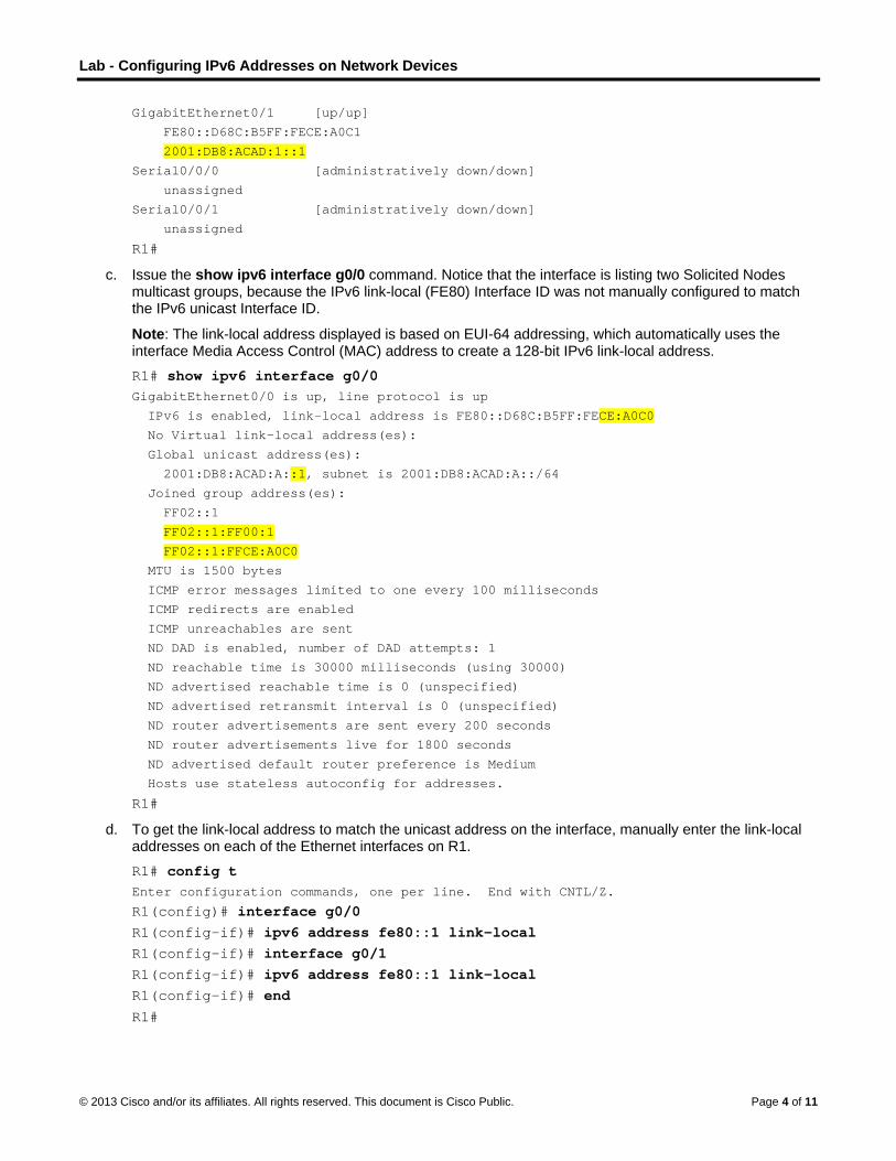
GigabitEthernet0/1 [up/up]
FE80::D68C:B5FF:FECE:A0C1
2001:DB8:ACAD:1::1
Serial0/0/0 [administratively down/down]
unassigned
Serial0/0/1 [administratively down/down]
unassigned
R1#
c. Issue the show ipv6 interface g0/0 command. Notice that the interface is listing two Solicited Nodes multicast groups, because the IPv6 link-local (FE80) Interface ID was not manually configured to match the IPv6 unicast Interface ID.
Note: The link-local address displayed is based on EUI-64 addressing, which automatically uses the interface Media Access Control (MAC) address to create a 128-bit IPv6 link-local address. R1# show ipv6 interface g0/0 GigabitEthernet0/0 is up, line protocol is up
IPv6 is enabled, link-local address is FE80::D68C:B5FF:FECE:A0C0
No Virtual link-local address(es):
Global unicast address(es):
2001:DB8:ACAD:A::1, subnet is 2001:DB8:ACAD:A::/64
Joined group address(es):
FF02::1
FF02::1:FF00:1
FF02::1:FFCE:A0C0
MTU is 1500 bytes
ICMP error messages limited to one every 100 milliseconds
ICMP redirects are enabled
ICMP unreachables are sent
ND DAD is enabled, number of DAD attempts: 1
ND reachable time is 30000 milliseconds (using 30000)
ND advertised reachable time is 0 (unspecified)
ND advertised retransmit interval is 0 (unspecified)
ND router advertisements are sent every 200 seconds
ND router advertisements live for 1800 seconds
ND advertised default router preference is Medium
Hosts use stateless autoconfig for addresses.
R1#
d. To get the link-local address to match the unicast address on the interface, manually enter the link-local addresses on each of the Ethernet interfaces on R1. R1# config t Enter configuration commands, one per line. End with CNTL/Z.
R1(config)# interface g0/0 R1(config-if)# ipv6 address fe80::1 link-local R1(config-if)# interface g0/1 R1(config-if)# ipv6 address fe80::1 link-local R1(config-if)# end R1#

Lab - Configuring IPv6 Addresses on Network Devices
© 2013 Cisco and/or its affiliates. All rights reserved. This document is Cisco Public. Page 5 of 11
Note: Each router interface belongs to a separate network. Packets with a link-local address never leave the local network; therefore, you can use the same link-local address on both interfaces.
e. Re-issue the show ipv6 interface g0/0 command. Notice that the link-local address has been changed to FE80::1 and that there is only one Solicited Nodes multicast group listed. R1# show ipv6 interface g0/0 GigabitEthernet0/0 is up, line protocol is up
IPv6 is enabled, link-local address is FE80::1
No Virtual link-local address(es):
Global unicast address(es):
2001:DB8:ACAD:A::1, subnet is 2001:DB8:ACAD:A::/64
Joined group address(es):
FF02::1
FF02::1:FF00:1
MTU is 1500 bytes
ICMP error messages limited to one every 100 milliseconds
ICMP redirects are enabled
ICMP unreachables are sent
ND DAD is enabled, number of DAD attempts: 1
ND reachable time is 30000 milliseconds (using 30000)
ND advertised reachable time is 0 (unspecified)
ND advertised retransmit interval is 0 (unspecified)
ND router advertisements are sent every 200 seconds
ND router advertisements live for 1800 seconds
ND advertised default router preference is Medium
Hosts use stateless autoconfig for addresses.
R1#
What multicast groups have been assigned to interface G0/0?
Step 2: Enable IPv6 routing on R1.
a. On a PC-B command prompt, enter the ipconfig command to examine IPv6 address information assigned to the PC interface.

Lab - Configuring IPv6 Addresses on Network Devices
© 2013 Cisco and/or its affiliates. All rights reserved. This document is Cisco Public. Page 6 of 11
Has an IPv6 unicast address been assigned to the network interface card (NIC) on PC-B?
b. Enable IPv6 routing on R1 using the IPv6 unicast-routing command. R1 # configure terminal R1(config)# ipv6 unicast-routing R1(config)# exit R1# *Dec 17 18:29:07.415: %SYS-5-CONFIG_I: Configured from console by console
c. Use the show ipv6 interface g0/0 command to see what multicast groups are assigned to interface G0/0. Notice that the all-router multicast group (FF02::2) now appears in the group list for interface G0/0.
Note: This will allow the PCs to obtain their IP address and default gateway information automatically using Stateless Address Autoconfiguration (SLAAC). R1# show ipv6 interface g0/0 GigabitEthernet0/0 is up, line protocol is up
IPv6 is enabled, link-local address is FE80::1
No Virtual link-local address(es):
Global unicast address(es):
2001:DB8:ACAD:A::1, subnet is 2001:DB8:ACAD:A::/64 [EUI]
Joined group address(es):
FF02::1
FF02::2
FF02::1:FF00:1
MTU is 1500 bytes
ICMP error messages limited to one every 100 milliseconds
ICMP redirects are enabled
ICMP unreachables are sent
ND DAD is enabled, number of DAD attempts: 1
ND reachable time is 30000 milliseconds (using 30000)
ND advertised reachable time is 0 (unspecified)
ND advertised retransmit interval is 0 (unspecified)
ND router advertisements are sent every 200 seconds
ND router advertisements live for 1800 seconds
ND advertised default router preference is Medium
Hosts use stateless autoconfig for addresses.
R1#
d. Now that R1 is part of the all-router multicast group, re-issue the ipconfig command on PC-B. Examine the IPv6 address information.

Lab - Configuring IPv6 Addresses on Network Devices
© 2013 Cisco and/or its affiliates. All rights reserved. This document is Cisco Public. Page 7 of 11
Why did PC-B receive the Global Routing Prefix and Subnet ID that you configured on R1?
Step 3: Assign IPv6 addresses to the management interface (SVI) on S1.
a. Assign the IPv6 address listed in the Addressing Table to the management interface (VLAN 1) on S1. Also assign a link-local address for this interface. IPv6 command syntax is the same as on the router.
b. Verify that the IPv6 addresses are properly assigned to the management interface using the show ipv6 interface vlan1 command.
Step 4: Assign static IPv6 addresses to the PCs.
a. Open the Local Area Connection Properties window on PC-A. Select Internet Protocol Version 6 (TCP/IPv6) and click Properties.

Lab - Configuring IPv6 Addresses on Network Devices
© 2013 Cisco and/or its affiliates. All rights reserved. This document is Cisco Public. Page 8 of 11
b. Click the Use the following IPv6 address radio button. Refer to the Addressing Table and enter the IPv6 address, Subnet prefix length, and Default gateway information. Click OK.
c. Click Close to close the Local Area Connection Properties window.

Lab - Configuring IPv6 Addresses on Network Devices
© 2013 Cisco and/or its affiliates. All rights reserved. This document is Cisco Public. Page 9 of 11
d. Repeat Steps 4a to c to enter the static IPv6 information on PC-B. For the correct IPv6 address information, refer to the Addressing Table.
e. Issue the ipconfig command from the command line on PC-B to verify the IPv6 address information.
Part 3: Verify End-to-End Connectivity a. From PC-A, ping FE80::1. This is the link-local address assigned to G0/1 on R1.
Note: You can also test connectivity by using the global unicast address, instead of the link-local address.
b. Ping the S1 management interface from PC-A.
c. Use the tracert command on PC-A to verify that you have end-to-end connectivity to PC-B.

Lab - Configuring IPv6 Addresses on Network Devices
© 2013 Cisco and/or its affiliates. All rights reserved. This document is Cisco Public. Page 10 of 11
d. From PC-B, ping PC-A.
e. From PC-B, ping the link-local address for G0/0 on R1.
Note: If end-to-end connectivity is not established, troubleshoot your IPv6 address assignments to verify that you entered the addresses correctly on all devices.
Reflection 1. Why can the same link-local address, FE80::1, be assigned to both Ethernet interfaces on R1?
2. What is the Subnet ID of the IPv6 unicast address 2001:db8:acad::aaaa:1234/64?

Lab - Configuring IPv6 Addresses on Network Devices
© 2013 Cisco and/or its affiliates. All rights reserved. This document is Cisco Public. Page 11 of 11
Router Interface Summary Table
Router Interface Summary
Router Model Ethernet Interface #1 Ethernet Interface #2 Serial Interface #1 Serial Interface #2
1800 Fast Ethernet 0/0 (F0/0)
Fast Ethernet 0/1 (F0/1)
Serial 0/0/0 (S0/0/0) Serial 0/0/1 (S0/0/1)
1900 Gigabit Ethernet 0/0 (G0/0)
Gigabit Ethernet 0/1 (G0/1)
Serial 0/0/0 (S0/0/0) Serial 0/0/1 (S0/0/1)
2801 Fast Ethernet 0/0 (F0/0)
Fast Ethernet 0/1 (F0/1)
Serial 0/1/0 (S0/0/0) Serial 0/1/1 (S0/0/1)
2811 Fast Ethernet 0/0 (F0/0)
Fast Ethernet 0/1 (F0/1)
Serial 0/0/0 (S0/0/0) Serial 0/0/1 (S0/0/1)
2900 Gigabit Ethernet 0/0 (G0/0)
Gigabit Ethernet 0/1 (G0/1)
Serial 0/0/0 (S0/0/0) Serial 0/0/1 (S0/0/1)
Note: To find out how the router is configured, look at the interfaces to identify the type of router and how many interfaces the router has. There is no way to effectively list all the combinations of configurations for each router class. This table includes identifiers for the possible combinations of Ethernet and Serial interfaces in the device. The table does not include any other type of interface, even though a specific router may contain one. An example of this might be an ISDN BRI interface. The string in parenthesis is the legal abbreviation that can be used in Cisco IOS commands to represent the interface.