l plasma-anode electron gun research · focusing by the background plasma and the bennett pinch....
TRANSCRIPT
HAC REF G0950
l PLASMA-ANODE ELECTRON GUNRESEARCH
S R.W Schumacher and J. Santoru* Hughes Research Laboratories
3011 Malibu Canyon Road
Malibu, California 90265
May 1989
F49620-86-C-01 05Final Report
July 15, 1986 through February 15, 1989
I
I Prepared for
AIR FORCE OFFICE OF SCIENTIFIC RESEARCH
3 Boiling Air Force Base
Washington, DC 20332-6448 00
I
II
(Unclassified'SECURITY CLASSIFICATION OF THIS PAGE
[ Form ApprovedREPORT DOCUMENTATION PAGE IOA No. 07rOTed8
la. REPORT SECURITY CLASSIFICATION lb. RESTRICTIVE MARKINGS
Unclassified2a. SECURITY CLASSIFICATION AUTHORITY 3 .STRIBUTION/AVAILABILITY.F REPO
2b. DECLASSIFICATION /DOWNGRADING SCHEDULE 411~2 +
4. PERFORMING ORGANIZATION REPORT NUMBER(S) S. MONOTOj.! NIZjON REPORT NUMBER(S)
M-T . 8 9- 1 290I6,NAME OF PERFORMING ORGANIZATION 6b. OFFICE SYMBOL 7a. NAME OF MONITORING ORGANIZATION
(If applicable)Hughes Research Laboratories I (S a.
,6c. ADDRESS (City, State, and ZIPCode) 7b. ADDRESS (City, State, and ZIP Code)
* : u3011 Malibu Canyon Rd. _ c-e,.- z* I Malibu, CA 90265
I a. NAME OF FUNDING /SPONSORING 8b. OFFICE SYMBOL 9. PROCUREMENT INSTRUMENT IDENTIFICATION NUMBERORGANIZATION Air Force Office (if a pl,
of Scientific Research/NP F49620-86-C0105I Sc ADDRESS (City, State, and ZIP Code) 10. SOURCE OF FUNDING NUMBERS
SPROGRAM PROJECT TASK WORK UNITg.Bolling Air Force Base, Bldg.410 ACCESSION NO.Washington, DC 20332-6448
,. .1 1. TITLE (InclJude Security Classification)I; PLASMA-ANODE ELECTRON GUN RESEARCH
12. PERSONAL AUTHOR(S)
Robert W. Schumacher and Joseph Santoru13a. TYPE OF REPORT 13b. TIME COVERED 14. DATE OF REPORT (Year, Month, Day) IS. PAGE COUNT
iqL. FROM 7/15/R6 TO ZI,9 1989 May 30 6116. SUPPLEMENTARY NOTATION
117. COSATI CODES 18, SUBJECT TERMS (Continue on reverse if necesary and vcentify by block number)
I FIELD. GROUP SUB-GROUP Electron Sources Microwave GenerationI Electron Beams. . Bepnett Pinch
Beam Weapons (old rathndrp19. ABSTRACT (Continue on reverse if necessary and identify by block number)
The plasma-anode electron gun (PAG) is a new cold-cathode electron source whichexhibits many novel features. These include instant starting, no cathode heater power,minimal vacuum requirements, a nonpoisoning cathode, long-pulse operation without gapclosure, and beam modulation at ground potential with constant beam energy. The basicconcept involves a collective interaction between counterpropagating streams ofelectrons and ions in a high-voltage diode gap. A Pierce electron-gun configuration isemployed, but the thermionic cathode is replaced with a cold, secondary-electron-emitting electrode. Electron emission is stimulated by bombarding the cathode withhigh-energy ions. The ions are injected into the high-voltage gap through a griddedstructure from a plasma source, which is embedded inside the anode electrode. Thegridded structure serves as both a cathode for the plasma ischarge and as an anode for.--,
20. DISTRIBUTION/AVAILABILITY OF ABSTRACT 21. ABSTRACT SECURITY CLASSIFICATIONo UNCLASSIFIEDWUNLIMITED D SAME AS RPT. aOTIC USERS Uncla ifiedIE INDwIDUAL ,22b. TELEPH NE (Include Area Code) 22c. OFF E SY OL
:D Form 1473, JUN 86 Previous tjitorksare ok...ete. SECURITY CLASSIFICATION OF THIS PAGE
8 9 2-1 "T / (fnc1~sified
SECURITY CLAWFICATION OF IS PAGE
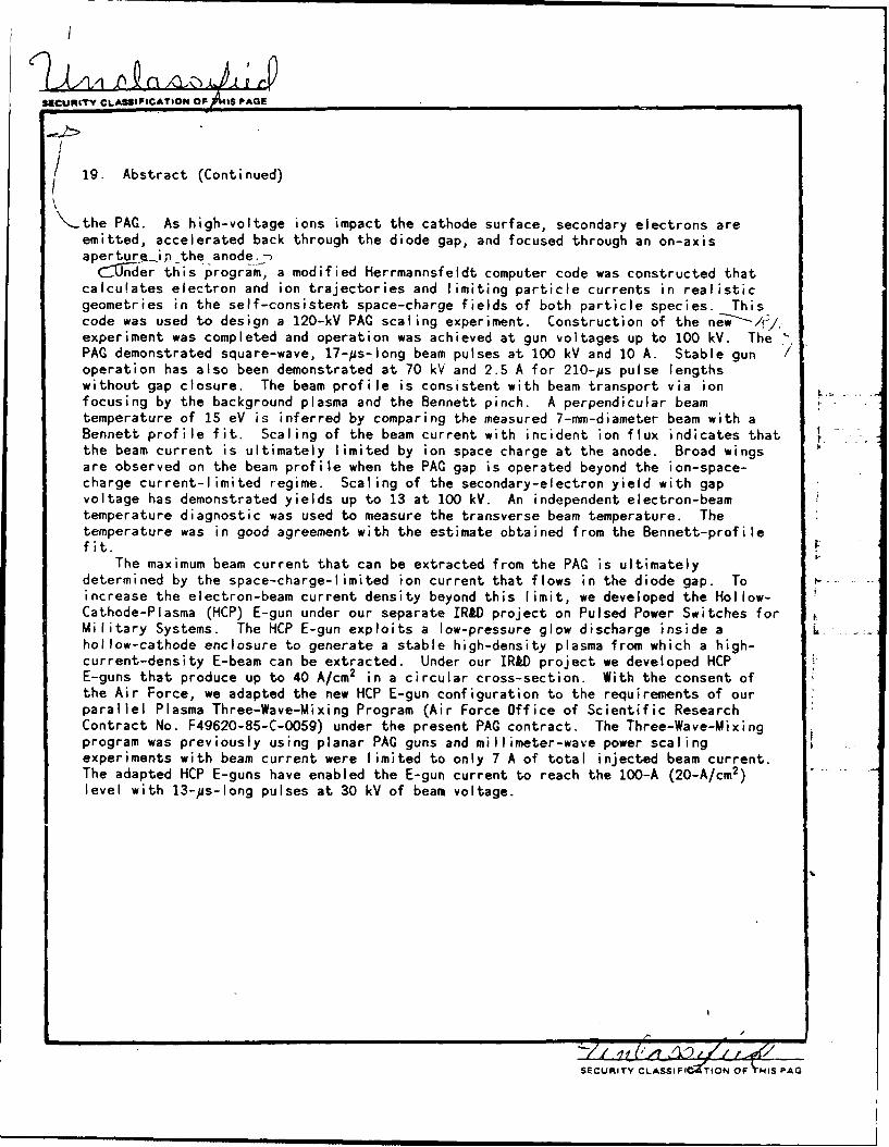
19. Abstract (Continued)
the PAG. As high-voltage ions impact the cathode surface, secondary electrons areemitted, accelerated back through the diode gap, and focused through an on-axisaperture.inthe anode.
1-nder this program, a modified Herrmannsfeldt computer code was constructed thatcalculates electron and ion trajectories and limiting particle currents in realisticgeometries in the self-consistent space-charge fields of both particle species. Thiscode was used to design a 120-kV PAC scaling experiment. Construction of the ne-w-/'/,experiment was completed and operation was achieved at gun voltages up to 100 kV. ThePAG demonstrated square-wave, 17-ps-long beam pulses at 100 kV and 10 A. Stable gunoperation has also been demonstrated at 70 kV and 2.5 A for 210-#s pulse lengthswithout gap closure. The beam profile is consistent with beam transport via ionfocusing by the background plasma and the Bennett pinch. A perpendicular beamtemperature of 15 eV is inferred by comparing the measured 7-mm-diameter beam with aBennett profile fit. Scaling of the beam current with incident ion flux indicates thatthe beam current is ultimately limited by ion space charge at the anode. Broad wingsare observed on the beam profile when the PAG gap is operated beyond the ion-space-charge current-limited regime. Scaling of the secondary-electron yield with gapvoltage has demonstrated yields up to 13 at 100 kV. An independent electron-beamtemperature diagnostic was used to measure the transverse beam temperature. Thetemperature was in good agreement with the estimate obtained from the Bennett-profilefit.
The maximum beam current that can be extracted from the PAC is ultimatelydetermined by the space-charge-limited ion current that flows in the diode gap. Toincrease the electron-beam current density beyond this limit, we developed the Hollow-Cathode-Plasma (HCP) E-gun under our separate IRAD project on Pulsed Power Switches forMilitary Systems. The HCP E-gun exploits a low-pressure glow discharge inside a .hollow-cathode enclosure to generate a stable high-density plasma from which a high-current-density E-beam can be extracted. Under our IR&D project we developed HCPE-guns that produce up to 40 A/cm2 in a circular cross-section. With the consent ofthe Air Force, we adapted the new HCP E-gun configuration to the requirements of ourparallel Plasma Three-Wave-Mixing Program (Air Force Office of Scientific ResearchContract No. F49620-85-C-0059) under the present PAC contract. The Three-Wave-Mixingprogram was previously using planar PAG guns and millimeter-wave power scalingexperiments with beam current were limited to only 7 A of total injected beam current.The adapted HCP E-guns have enabled the E-gun current to reach the 100-A (20-A/cm2)level with 13-ps-long pulses at 30 kV of beam voltage.
SECURITY CLAFIFe;TIONOF HIS PAG
TABLE OF CONTENTS
SECTION PAGE
1 INTRODUCTION........................................ 1
2 PLASMA-ANODE E-GtN CALCULATIONS AND)EXPERIMENTS......................................... 8
2.1 Computer-Code Developmentand Application ............................... g
2.2 120-kY PAG Scaling Experiment ...................
2.2.1 Experimental Apparatusand Diagnostics........................ 11
2.2.2 PAG Operation..........................1is
2.2.3 Parameter Scaling..................... 16
2.2.4 Electron-Beam Profiles ................. 25
2.2.5 Direct Beam-TemperatureDiagnostic............................. 32-
3 HOLLOW-CATHODE-PLASMA E-GUN EXPERIMENTS ............ 40
3.1 Hollow-Cathode-Plasma (HCP)E-gun Configuration........................... 41
3.2 HOP E-gun Adaptation forThree-Wave-Mixing............................. 43
3.3 HOP E-gun. Performance and Scaling ............. 45
4 INTERACTIONS..................... ................. 51
5 PUBLICATIONS....................... ............... 53
6 RESEARCH PERSONNEL................................. 54
REFERENCES..................A* f ~. . .... 55
l~Lt
'AwlU and /or-
Dst SpCeiai
I .. (04r"C
LIST OF ILLUSTRATIONS
FIGURE PAGEI1 Plasma-Anode E-gun (PAG) Concept ................ 3
2 Typical Operating Point of a PAGHigh-Voltage Gap ................................
3 Modified Hermannsfeldt-Code Runs at 80 kV and10 A Showing Electron Trajectories With (a) andWithout (b) The Presence of Ions in the Gap ..... 10
3 4 120-kV PAG-Scaling Experiment ................... 12
5 Photograph of the 120-kV PAG ScalingExperiment ......................................... 13
6 Photograph of the PAG Cathode andHigh-Voltage-Bushing Assembly ................... 14
7 Photograph of Narrow 5-mm-Diameter PAG Beam1 Operating cw at 40 kV and 10 mA ................. 17
8 Pulsed PAG Operation Demonstrating 10 Aof Cathode Current at 100 kV .................... 18
9 PAG Operation with 210-ps Pulse Length .......... 19
10 Cathode and Faraday-Cup Current Scaling WithIon-Source Discharge Current at Vb = 90 kV ...... 21
11 Cathode and Faraday-Cup Current Scaling WithIon-Source Discharge Current at Vb = 50 kV ...... 22
12 Electron Yield per Ion as a Functionof Beam Voltage ................................. 26
13 Beam Current Measured by 1-mm-Diameter
* Disk Probe .......................................... 28
14 Radial Beam Profile ............................. 29
3 15 Bennett-Pinch Effect............................ 30
16 Electron-Beam Profile is Consistent withBennett-Pinch Theory ............................ 33
17 Beam Profile With PAG Operating in the5 Ion-Space-Charge Current-Limited Regime ......... 34
av
U
ILIST OF ILLUSTRATIONS (Continued)
FIGURE PAGE
18 Schematic of the "Beam-Slit Shadowgraph"for Measurement of the TransverseElectron-Beam Temperature ........................... 36
19 Schematic of the 120-kV PAG Scaling Experimentwith a "Beam-Slit Shadowgraph" ...................... 37
20 Current Distribution Measured 7.9 cmDownstream of the Beam Slit ......................... 39
21 Hollow-Cathode-Plasma Electron-Gun3 Configuration ......................................... 42
22 Experimental Set-up for Testing the High-CurrentHCP E-gun .................... ...................... 44
23 HCP E-gun Pulsed-Power Circuit ...................... 46
24 Three-Wave-Mixing Experiment Driven byHCP E-guns ............................................ 47
f 25 HCP E-gun Waveforms .................................. 49
26 Beam Current Scaling with HC DischargeCurrent ................................................ 50
IviII£I
I
USECTION 1
INTRODUCTION
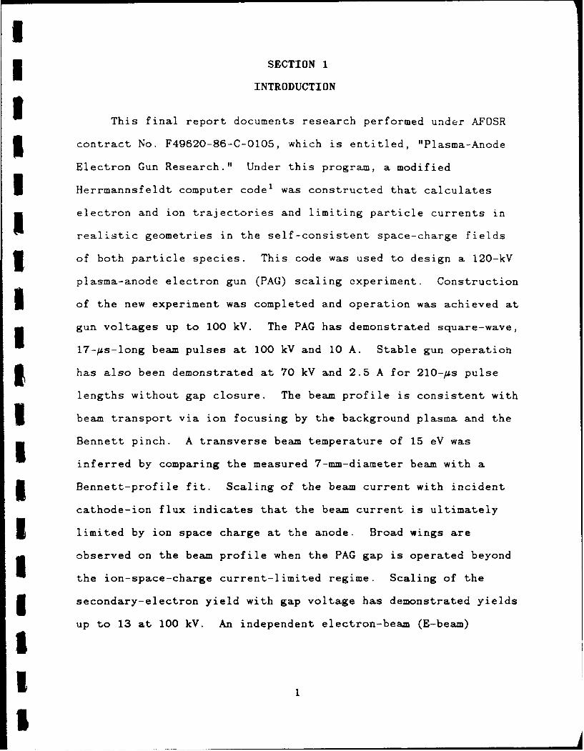
This final report documents research performed under AFOSR
3contract No. F49620-86-C-0105, which is entitled, "Plasma-Anode
Electron Gun Research." Under this program, a modified
I Herrmannsfeldt computer code1 was constructed that calculates
1 electron and ion trajectories and limiting particle currents in
realistic geometries in the self-consistent space-charge fields
of both particle species. This code was used to design a 120-kV
plasma-anode electron gun (PAG) scaling experiment. Construction
£of the new experiment was completed and operation was achieved atgun voltages up to 100 kV. The PAG has demonstrated square-wave,
17-/is-long beam pulses at 100 kV and 10 A. Stable gun operation
I has also been demonstrated at 70 kV and 2.5 A for 210-us pulse
lengths without gap closure. The beam profile is consistent with
I beam transport via ion focusing by the background plasma and the
Bennett pinch. A transverse beam temperature of 15 eV was
inferred by comparing the measured 7-mm-diameter beam with a
3 Bennett-profile fit. Scaling of the beam current with incident
cathode-ion flux indicates that the beam current is ultimately
3 limited by ion space charge at the anode. Broad wings are
observed on the beam profile when the PAG gap is operated beyond
the ion-space-charge current-limited regime. Scaling of the
5 secondary-electron yield with gap voltage has demonstrated yields
up to 13 at 100 kV. An independent electron-beam (E-beam)a3£
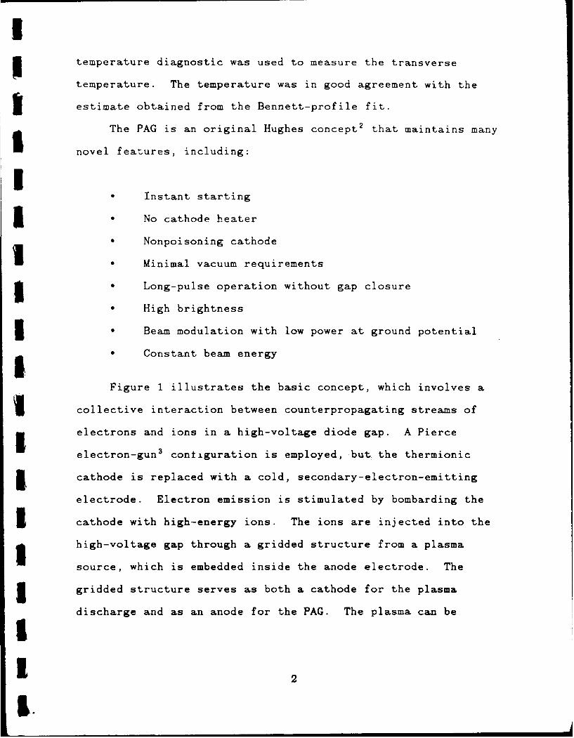
Itemperature diagnostic was used to measure the transverse
temperature. The temperature was in good agreement with the
estimate obtained from the Bennett-profile fit.
The PAG is an original Hughes concept 2 that maintains many
novel features, including:
I0 Instant starting
1 • No cathode heater
* Nonpoisoning cathode
1 Minimal vacuum requirements
I Long-pulse operation without gap closure
* High brightness
3 Beam modulation with low power at ground potential
• Constant beam energy
Figure 1 illustrates the basic concept, which involves a
Icollective interaction between counterpropagating streams ofelectrons and ions in a high-voltage diode gap. A Pierce
electron-gun3 contiguration is employed, but the thermionic
3, cathode is replaced with a cold, secondary-electron-emitting
electrode. Electron emission is stimulated by bombarding the
3 cathode with high-energy ions. The ions are injected into the
g high-voltage gap through a gridded structure from a plasma
source, which is embedded inside the anode electrode. The
5 gridded structure serves as both a cathode for the plasma
discharge and as an anode for the PAG. The plasma can be
21| 2
I.
tI LOW VOLTAGE (-1 kV)
5-HV PULSE
.AUXILIARY GRID BIAS
I CATHOE-'
WIRE-ANODEI ELECTRODE
LEED E-GUN ANODE \PAM
G (ION) SOURCE
j Figure 1. Plasma-anode E-gun (PAC) concept.
1 3
generated by various means, but the preferred approach is to use
a wire-anode glow discharge' S at low gas pressure (<50 mTorr).
As high-voltage ions impact the cathode surface, secondary
electrons are emitted and accelerated back through the diode gap.
If the proper electrode configuration is chosen (which accounts
3 for electron and ion space-charge in a self-consistent manner)
then electrostatic fields can be generated that focus the
Selectrons through the on-axis aperture in the anode to form a
laminar beam with a uniform circular cross section.
I Since gas from the plasma source in the anode may pass into
5 the high-voltage gap, the operating point of the gap must be
chosen so as to standoff high voltage against both vacuum- and
3 Paschen-breakdown mechanisms (as shown in Figure 2). This
selected operating point limits the voltage per gap to typically
200 kV. Beam acceleration to higher voltages can be accomplished
with multiple gaps.
Because the pressure limit is imposed by Paschen breakdown,
3 helium gas is usually employed since it provides the highest
voltage holdoff against Paschen breakdown relative to any other
I gas. Published data,6 data obtained in the Hughes E-beam
i controlled switch 7 (developed under Air Force contract
No. F33615-81-C-2009), and data obtained under this contract
5 indicate that a secondary-electron yield of 13 to 15 is obtained
for 100-keV helium-ion impact upon molybdenum surfaces in the
I presence of a background.helium gas.
34I
1000 14944-5R2
>.X VACUUM
~~~~BREAKDOWN RADW
>J OPE RATING POINT 5 ~r
0 jwa 10
I1o- 2 10-1 1 10
ELECTRODE GAP SPACING, cm
I Figure 2. Typical operating point of a PAG high-voltage gap.
1 5
The E-beam current in the PAG is controlled at low voltage
by modulating the ('1 kV) wire-anode discharge at the ground-
potential environment of the anode electrode. Since the plasma
is confined within the gridded anode structure (the electrons
cannot penetrate into the anode-cathode gap because of the high
electron-repelling E-gun potential), plasma closure of the high-
voltage gap cannot occur and long-pulse (>>1 js) operation is
achieved. Modulation of the plasma source modulates the ion flux
incident upon the cathode which, in turn, controls the beam
current. A monoenergetic beam is obtained throughout the beam
pulse because the E-beam is switched ON and OFF by the plasma
source and not by the high-volt-ge supply for the cathode. Low-
energy electrons, which result from the rise and fall of the
cathode voltage in conventional pulsed beams, will not be
present. All of this is accomplished without heater power and
without high-vacuum-environment requirements because the
ordinary-metal cathode used in the PAG cannot be poisoned.
The maximum bea. cur,'ent that can be extracted from the PAG
is ultimately determined by the space-charge-limited ion current
that flows in the diode gap. To increase the electron-beam
current density beyond this limit, we developed the Hollow-
Cathode-Plasma (HCP) E-gun under our separate IR&D project on
j Pulsed Power Switches for Military Systems. The HCP E-gun
exploits a low-pressure glow discharge inside a hollow-cathode
5 enclosure to generate a stable high-density plasma from which a
II 6
I
I high-current-density E-beam can be extracted. Under our IR&D
3 project we developed HCP E-guns that produce up to 40 A/cm 2 in a
circular cross-section. With the consent of the Air Force, we
5 adapted the HOP E-gun configuration to the requirements of our
parallel Plasma Three-Wave-Mixing Program (AFOSR Contract
3 No. F49620-85-C-0059) under the present PAG contract. The Three-
5 Wave-Mixing Program was previously using planar PAG guns and
millimeter-wave power scaling experiments with beam current were
3 limited to only 7 A of total injected beam current. The adapted
HCP E-guns have enabled the E-gun current to reach the 100-A
3 (20-A/cm2) level with 13-#s-long pulses at 30 kV of beam voltage.
Development of the plasma-anode electron-gun (E-gun) and the
HCP E-gun may have a significant impact on many important high-
5 power Air Force systems. For example, they may improve the
performance and decrease the auxiliary power requirements of
I conventional devices, such as klystrons and traveling-wave tubes,
that are presently deployed on aircraft and satellites. These
E-guns may also provide one of the key enabling technologies
required for new Air Force systems, such as free-electron lasers,
high-power excimer lasers, and E-beam weapons.
IIII!I
7I
SECTION 2
PLASMA-ANODE E-GUN CALCULATIONS AND EXPERIMENTS
5 In this section we discuss our progress in computer-code
development and application, PAG scaling experiments, beam
3 profile measurements, and beam-temperature-diagnostic systems.
1 2.1 COMPUTER-CODE DEVELOPMENT AND APPLICATION
3 We have developed and applied new computer programs that are
capable of computing the trajectories of electrons and ions
through the PAG in the self-consistent space-charge field of both
species. Realistic boundary and electrode potentials are used as
input data. Under a separate contract with Hughes, which was
5 supported by IR&D funds, Dr. W. Herrmannsfeldt of Stanford
University revised an earlier version of his electron
trajectories code to self-consistently compute the trajectories
and space-charge fields of more than one charged species in an
E-gun, with each species having an arbitrarily specified charge-
5 to-mass ratio. The code was adapted for the VAX 11/785 and 8650
computers at Hughes Research Laboratories (HRL).
3 An electron-generation code that supports the new
Herrmannsfeldt program was also constructed. The function of
this latter code is to iteratively generate the initial
3 conditions for the electrons at the cathode surface by
multiplying the local ion flux at the cathode by the appropriate
3 secondary-emission coefficient.
18
5 The new Herrmannsfeldt code maintains the versatility of the
original code. For example, the number of iterations on the
space-charge computation can be reduced to one to simulate space-
charge neutralization (i.e., remove the self-consistent space-
Icharge field) by plasma in specified regions of some PAG designs.3 This versatility was exploited when the code was used to
design the 120-kV PAG scaling experiment. Many different code
5 runs were completed in order to arrive at an optimal PAG design.
During the course of these runs it became evident that the new
code was revealing important physics that we were not able to see
Iusing an earlier single-species code. One of the most important
features that was revealed was a reduction in the electron
3 emittance which was made possible by the presence of the ion
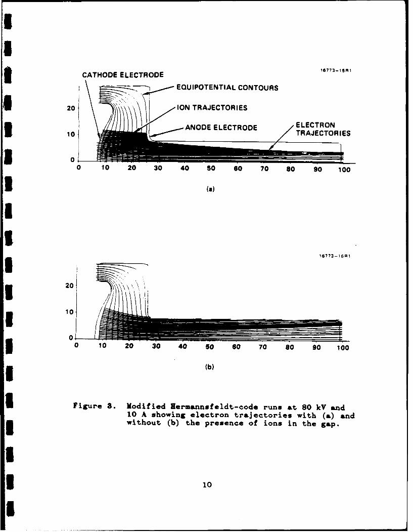
space charge. This effect is illustrated dramatically by the
Sruns shown in Figure 3 for the experimental PAG operating at3 80 kV and 10 A. The two trajectory plots show the transport of
electrons with identical initial conditions, but with
5 [Figure 3(a)] and without [Figure 3(b)] the presence of positive
helium ions. E-beam focusing and collimation are greatly
I assisted by the presence of the ion space charge. Perturbation
3 analyses of these trajectories reveal that the greatest influence
of the ion space charge is near the cathode where the electron
3 velocities are small.
1 2.2 120-kV PAG SCALING EXPERIMENT
3 The second task in the PAG program was the design,
fabrication, and operation of a 120-kV PAG scaling experiment. In
3 9
5
CATHODE ELECTRODE 16773-iSnl
I EQUIPOTENTIAL CONTOURS
U20 INTAETREANODEELECRODEELECTRON
10 AOEEETOETRAJECTORIES
I00 10 20 30 40 50 60 70 a8.0 9 0 100
3 (a)
16773-i6Ri
030 10 20 30 40 s0 60 7 .0 8 0 9 0 100
(b)
I Figure 3. Modified Iermannsfeldt-code runs &t 80 kV and10 A showing electron trajectories with (&) and3 without (b) the presence of ions in the gap.
3 10
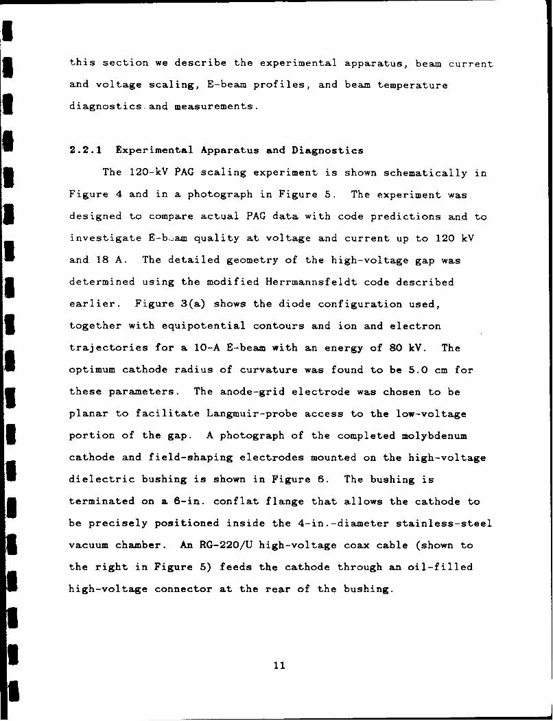
this section we describe the experimental apparatus, beam current
and voltage scaling, E-beam profiles, and beam temperature
diagnostics and measurements.
1 2.2.1 Experimental Apparatus and Diagnostics
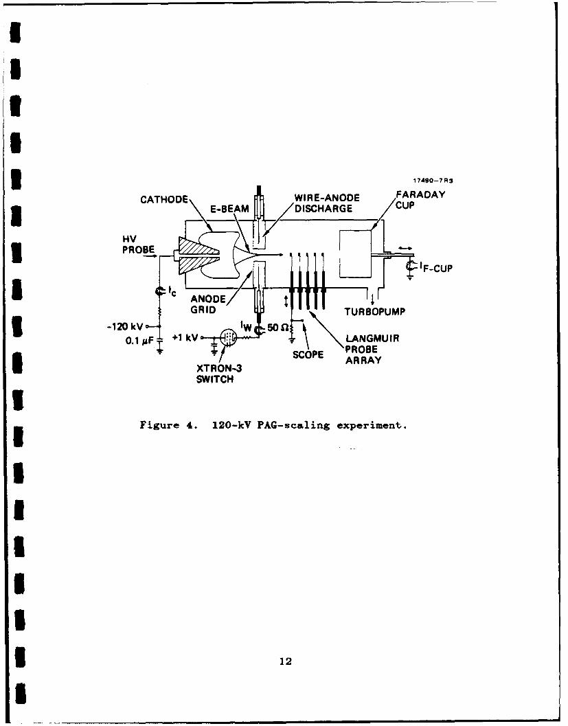
3 The 120-kV PAG scaling experiment is shown schematically in
Figure 4 and in a photograph in Figure 5. The experiment was
5 designed to compare actual PAG data with code predictions and to
investigate E-boam quality at voltage and current up to 120 kV
and 18 A. The detailed geometry of the high-voltage gap was
5 determined using the modified Herrmannsfeldt code described
earlier. Figure 3(a) shows the diode configuration used,
3 together with equipotential contours and ion and electron
trajectories for a 10-A E-beam with an energy of 80 kV. The
optimum cathode radius of curvature was found to be 5.0 cm for
3 these parameters. The anode-grid electrode was chosen to be
planar to facilitate Langmuir-probe access to the low-voltage
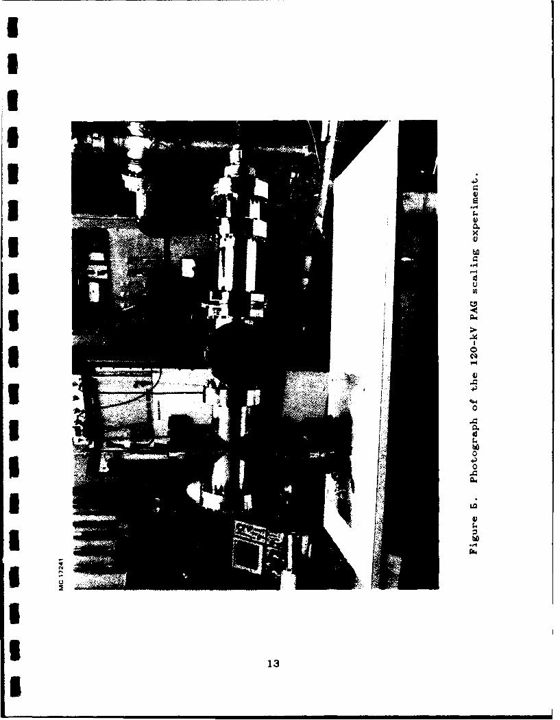
3 portion of the gap. A photograph of the completed molybdenum
cathode and field-shaping electrodes mounted on the high-voltage
dielectric bushing is shown in Figure 6. The bushing is
3 terminated on a 6-in. conflat flange that allows the cathode to
be precisely positioned inside the 4-in.-diameter stainless-steel
vacuum chamber. An RG-220/U high-voltage coax cable (shown to
the right in Figure 5) feeds the cathode through an oil-filled
high-voltage connector at the rear of the bushing.
11
I
I3 r -,17490-7 R3
WIRE-ANODE FARADAY3E-BEAM /DISCHARGE CUP
i~~E CUNOEP IHV3 PROBEIF-CUP
-120kV- RID W 5w 9Z URBOPUMP
0.1/ FT +1 kV LANGMUIR'- .. SCOPE PROBE
SCOPE ARRAYSXTRON-3
SWITCHIFigure 4. 120-kV PAG-scaling experiment.
II
I
I1 12
3
IIII3
:4
x
I hO.f-I
I U
* ~m.-~
£ 0ci
4)
ti-I1 0
:4hO0
4)*I
:4
hO"-4
I1 13
I
MC 17240
1 4
I3 A wide range of diagnostic equipment has been designed and
assembled for the experiment. Electrical diagnostics consist of
3 voltage dividers to measure the cathode and ion-source voltages,
and current transformers to measure the cathode, E-beam, and ion-
I source currents. A three-dimensional probe array has been
3 constructed to measure the beam profiles and divergence angle,
and a Faraday cup has been constructed to measure the total beam
3 current. As shown in Figure 4, the Faraday cup can be positioned
just downstream of the anode assembly to intercept the entire
I beam envelope. The cup is moved further downstream when probe
3 measurements are made. A "beam-slit shadowgraph" was used with
the probe array to measure the parallel beam temperature.
3 The E-beam diagnostics discussed above are mounted on the
two, four-way conflat-flange crosses shown in Figure 5. This
* arrangement offers optimum flexibility and diagnostic access to
g the E-beam. The experiment is evacuated by a turbomolecular pump
to avoid the surface-contamination problems associated with
3 diffusion pumps. The helium gas pressure is regulated in the
range of 10 to 50 mTorr by flowing gas into the system through a
I leak valve.
I 2.2.2 PAG Operation
5 The experimental PAG has demonstrated well-collimated, high-
quality beams in good agreement with the predictions of the
5 modified Herrmannsfeldt code. The E-beam was focused
electrostatically by the diode geometry to form a 7-mm-diameter
I15
I3 collimated beam, which was transported over the 1-m length of the
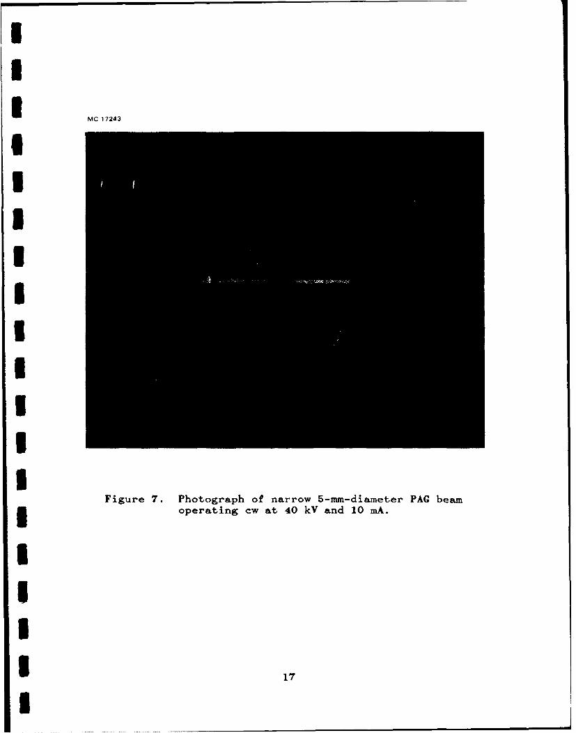
experiment without the aid of magnetic-focusing fields. Figure 7
3 is a photograph of the beam operating continuously at 40 kV and
10 mA. The photograph was taken through a Pyrex window mounted
on one of the four-way crosses shown in Figure 5. The path of
3 the narrow beam is indicated by optical line radiation emitted by
neutral atoms that are excited by the beam.
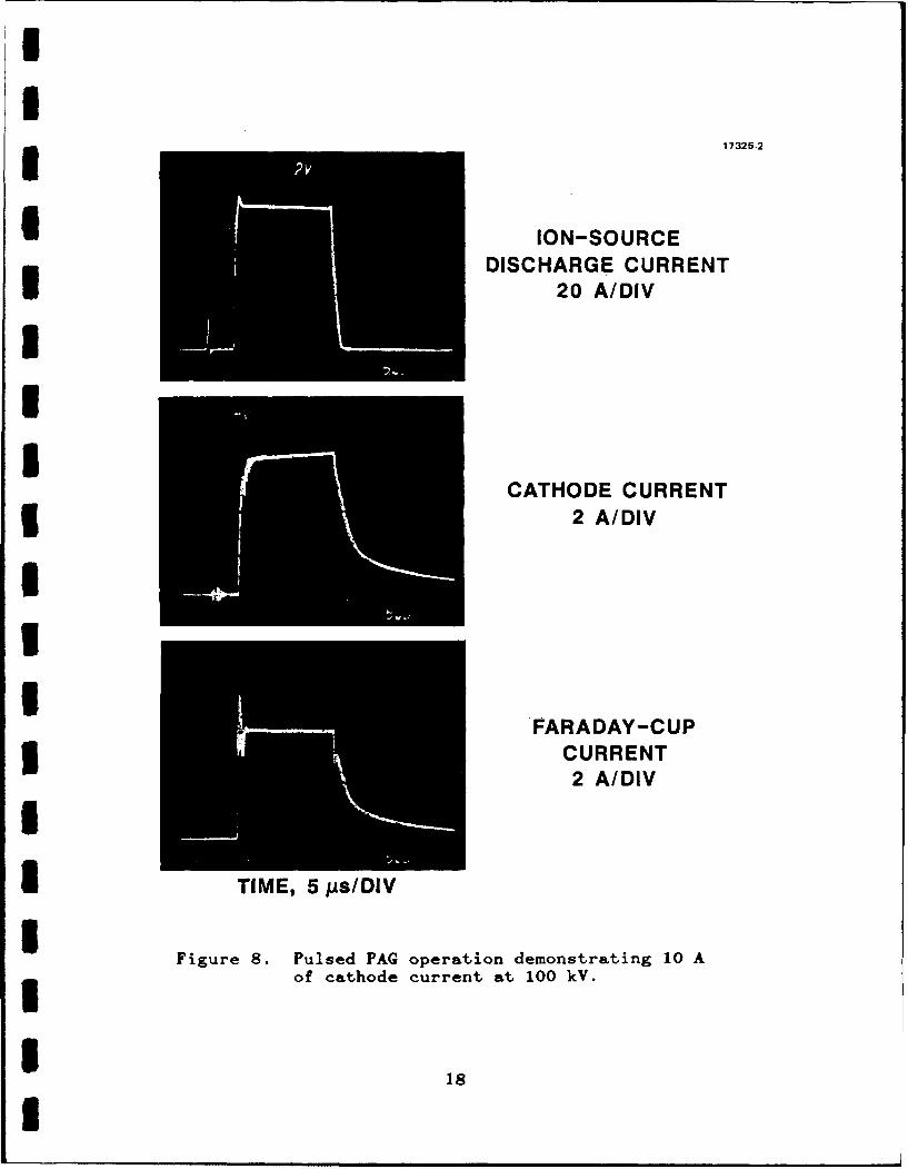
3 Figure 8 shows oscilloscope waveforms for a 17-As-wide pulse
with a beam voltage of 100 kV. The ion-source discharge current
I was modulated at 100 A using the CROSSATRON switch as shown in
5 IFigure 4. The discharge generated 10 A of cathode current, which
is the sum of the E-beam and incident-ion currents. In this case
3 the Faraday cup collected 8 A of beam current. We have also
demonstrated stable PAG operation with ultrawide beam pulses
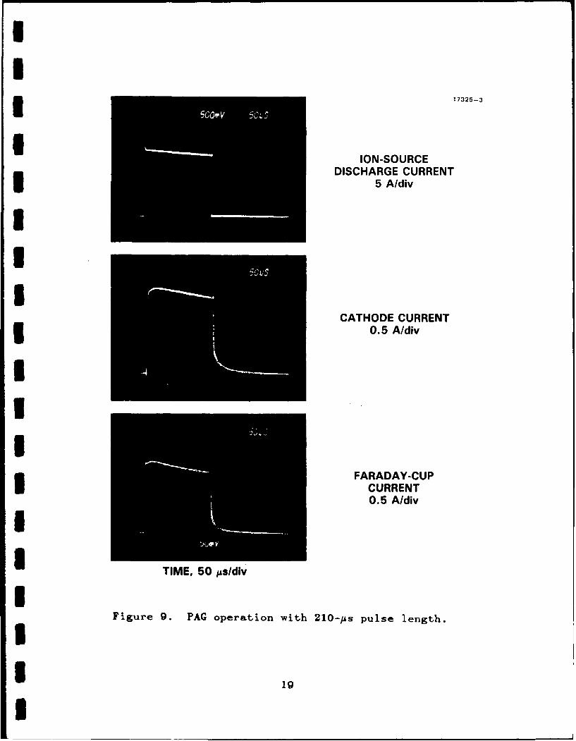
I without high-voltage-gap closure. Figure 9 shows operation with
pulse widths of 210 ps at 2.5 A of Faraday-cup current at 70-kV
beam voltage. The droop in the current waveforms in Figure 9 is
3 caused by the voltage droop in the capacitor bank supplying the
ion-source discharge current and is not a feature of the PAG.
I The droop can be eliminated by simply increasing the size of the
* capacitor bank.
3 2.2.3 Parameter Scaling
In these experiments we measured the scaling of Faraday-cup
5 and cathode currents with ion-source discharge current and the
beam voltage. We found that the E-beam current is ultimately
316
IIU MC 17243
IIIUaIIIII
Figure 7. Photograph of narrow 5-mm-diameter PAG beam3 operating cw at 40 kY and 10 mA.
ISU
17
I
'II1 i17325-2
I ION-SOURCEDISCHARGE CURRENT
120 A/DIV
U
ICATHODE CURRENT
I2 A/DIV
I
FARADAY-CUP5 CURRENT
2 A/DIVI
U TIME, 5 ps/DIV
Figure 8. Pulsed PAG operation demonstrating 10 Aof cathode current at I00 kV.
I18
II3 17325-3
ION-SOURCEDISCHARGE CURRENT
5 A/div
UUI
CATHODE CURRENT0.5 A/div
II
FARADAY-CUP
CURRENT0.5 A/divI
a TIME, 50 As/div
IFigure 9. PAG operation with 210-ps pulse length.
1
I 1
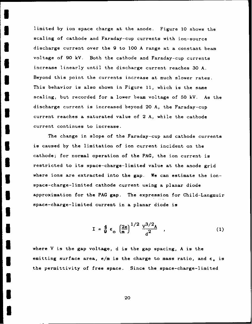
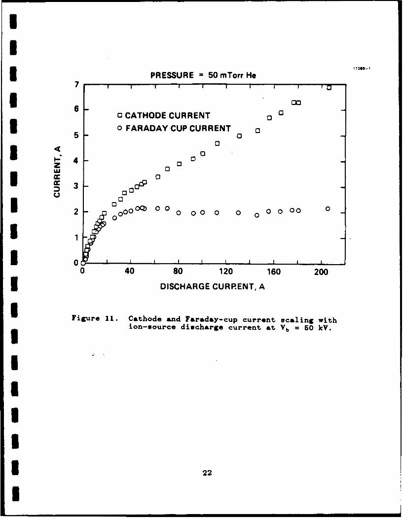
U3 limited by ion space charge at the anode. Figure 10 shows the
scaling of cathode and Faraday-cup currents with ion-source
3 discharge current over the 9 to 100 A range at a constant beam
voltage of 90 kV. Both the cathode and Faraday-cup currents
increase linearly until the discharge current reaches 30 A.
* Beyond this point the currents increase at much slower rates.
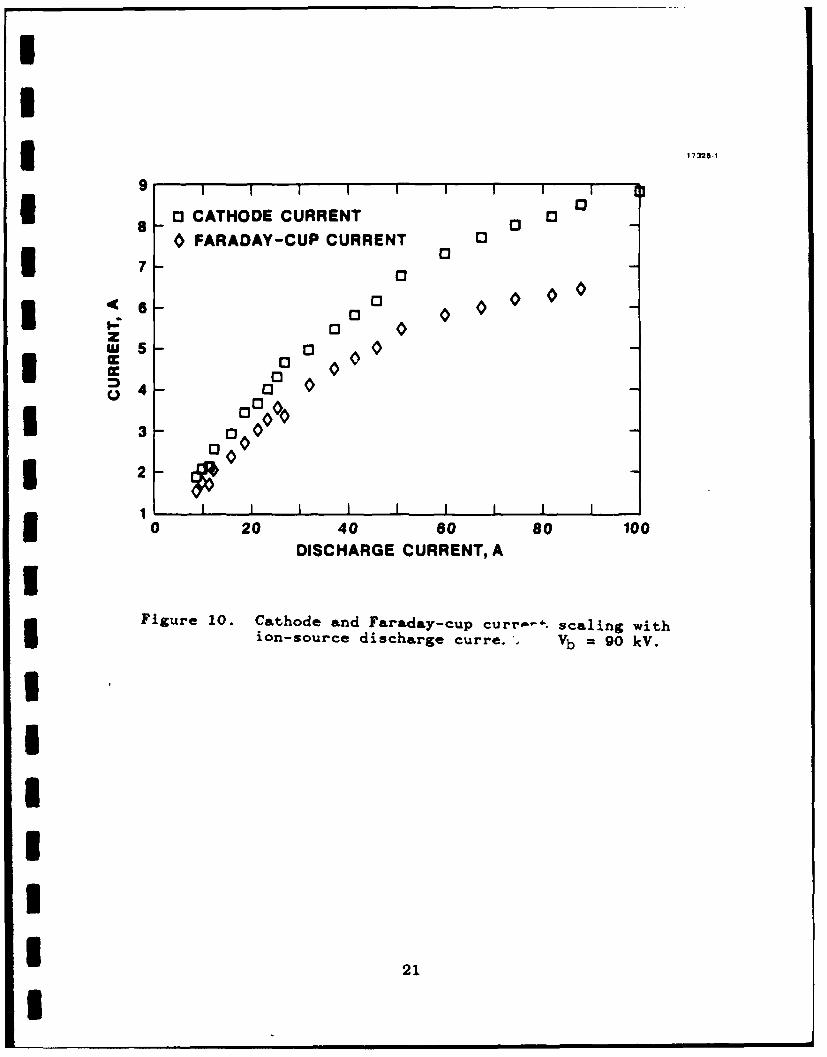
This behavior is also shown in Figure 11, which is the same
3 scaling, but recorded for a lower beam voltage of 50 kV. As the
discharge current is increased beyond 20 A, the Faraday-cup
current reaches a saturated value of 2 A, while the cathode
3 current continues to increase.
The change in slope of the Faraday-cup and cathode currents
3 is caused by the limitation of ion current incident on the
cathode; for normal operation of the PAG, the ion current is
I restricted to its space-charge-limited value at the anode grid
where ions are extracted into the gap. We can estimate the ion-
space-charge-limited cathode current using a planar diode
3 approximation for the PAG gap. The expression for Child-Langmuir
space-charge-limited current in a planar diode isI(2-e I /2 V3/2A
-E d , (1)
I where V is the gap voltage, d is the gap spacing, A is the
3emitting surface area, e/m is the charge to mass ratio, and E. isthe permittivity of free space. Since the space-charge-limited
2* 20
I
3 17225.1
9
8 0 CATHODE CURRENT0 00 FARADAY-CUP CURRENT0
00
13 0
III0 20 40 s0 s0 100
DISCHARGE CURRENT, A
Figure 10. Cathode and Faraday-cup curr--. scaling with
ion-source discharge curre.. Vb =90 kV.
I 21
PRESSURE =50 mTorr He7 17 1 1C
6 C3 CATHODE CURRENT 00
0 OFARADAY CUP CURRENT 00
4 ~0z 0 0cc 0
000
00
0
0 40 80 120 160 200
3 DISCHARGE CURRENT, A
U Figure 11. Cathode and Faraday-cup current scaling withion-source discharge current &t Vb 50 kV.
* 22
Icurrent scales as m 1 / 2, ion emission at the anode will become
space-charge limited well before electron emission at the
3 cathode. For singly charged helium ions, the space-charge-
limited ion current isII. = 2.72 x 10⁻⁸ V3 /2 A
Sd 2 (2)
U The total cathode current is the sum of the ion and E-beam
3 currents, or
I Ic =i + Ib (3)
I But the electron-beam current can be expressed in terms of the
incident ion current and the secondary yield, y, as
3 b = 7 I i (4)
3 Combining Eqs. (2), (3) and (4), the saturated cathode current is
I = 2.72 x 10 - 8 (7+ld 2 V3 / 2 A (5)
Using the PAG experiment parameters A = 3.8 cm 2 , d = 3.3 cm,
I Vb = 90 kV, and 7 = 13, Eq. (5) predicts a saturated cathode
3 current of 3.6 A.
2* 23
I
IThe observed linear scaling of cathode current with ion-
source discharge current in Figure 10 shows the saturation to
3 begin at the slightly higher value of 4.7 A. This correspondence
is sufficiently close considering the level of approximation
which does not include the geometrical enhancement of ion
perveance resulting from the nonplanar gap configuration. At the
lower beam voltage of 50 kV, the cathode current begins to
3 saturate (Figure 11) at a lower value (~1.9 A) which is
consistent with the ion-space-charge-limited voltage scaling
U predicted by Eq. (5).
5 As the discharge current is increased beyond IC, in
Figures 10 and 11, the cathode current continues to increase.
3 This is due to penetration of the ion-space-charge cloud at the
anode into the high-voltage gap; a phenomena which reduces the
I effective cathode-to-anode spacing (i.e., d < 3.3 cm), increases
3 the ion-emitting area, and thereby increases I1 Although the
cathode current continues to increase, the Faraday-cup current
3 approaches a constant value in Figures 10 and 11. The Faraday
cup, therefore, does not collect all the beam current which is
* generated in this regime; an observation which suggests that the
beam becomes defocused when the gap is operated beyond the ion-
space-charge limit. Beam profiles presented in the next section
3 verify that this is indeed the case. The beam defocusing is
caused by the release of ions from the extended ion space charge
3 cloud at the anode. Ions from the edge of expanded cloud are
released on trajectories which map onto the cathode surface at
* 24
I
Ilarge radii from the PAG axis. These ions stimulate the emission
of secondary electrons (at large radii on the cathode) which are
* over focused and cross the gun axis thus creating a "halo" or
broad wings on the beam profile.
Finally, by comparing the cathode and Faraday-cup currents
3 at each beam voltage we can deduce the secondary electron yield
using the equation
I7 = Ib/(Ib+ Ic (6)
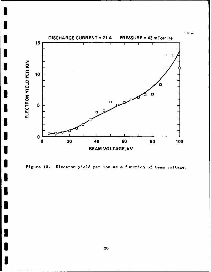
which is derived by combining Eqs. (3) and (4). Figure 12 shows
the computed electron yield per ion to scale up a value of 13 at
3 voltages up to 100 kV. This plot was prepared by assuming that
all the beam current is collected by the Faraday cup. However,
3 since the discharge current was 21 A for this experiment, the PAG
was operating in the ion-space-charge current-limited mode for
I voltages less than 50 kV (as shown in Figure 11). Below 50 kV,
3 therefore, the measured yields are smaller than those actually
obtained since some portion of the beam falls outside the
3 Faraday-cup entrance aperture in this regime.
I 2.2.4 Electron-Beam Profiles
* Radial beam profiles were measured using the array of disk
probes shown in Figure 4. The probe current was measured at each
3 radial position using the 0 = 0" and 900 probe orientations as
2
* 2
UI
17285 -a
DISCHARGE CURRENT= 21 A PRESSURE = 43 mTorr He15
* 0
z0 0
w 10
0.0
I 00
U z0U-
I 00 20 40 60 80 100
3 BEAM VOLTAGE, kV
U Figure 12. Electron yield per ion as a function of beam voltage.
IUIII
I
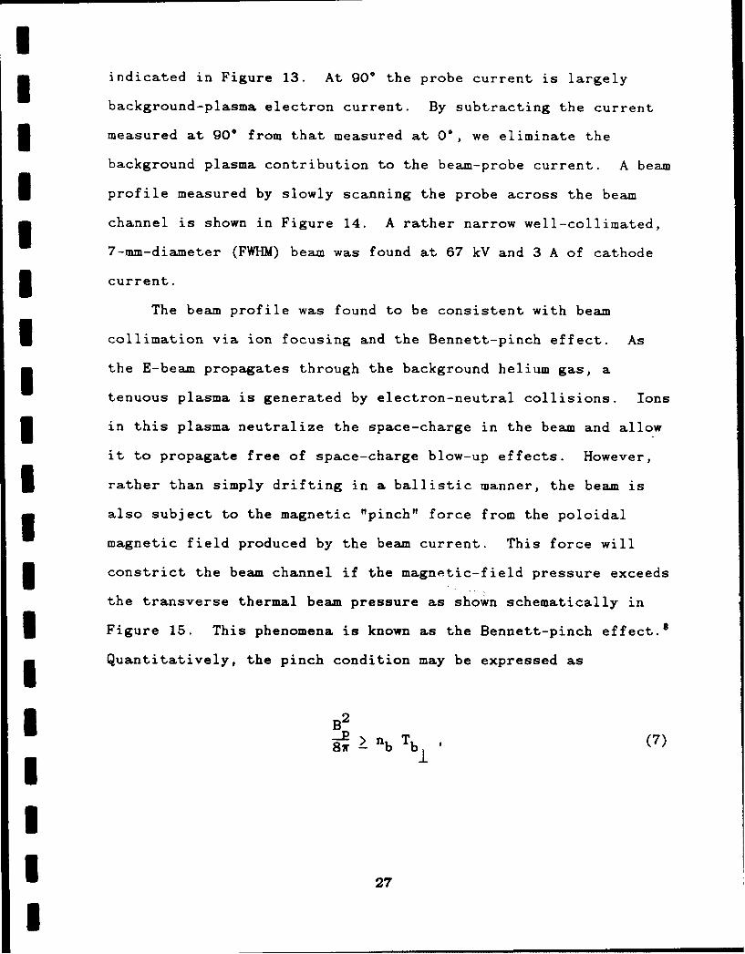
Iindicated in Figure 13. At 90" the probe current is largely
background-plasma electron current. By subtracting the current
3 measured at 900 from that measured at 00, we eliminate the
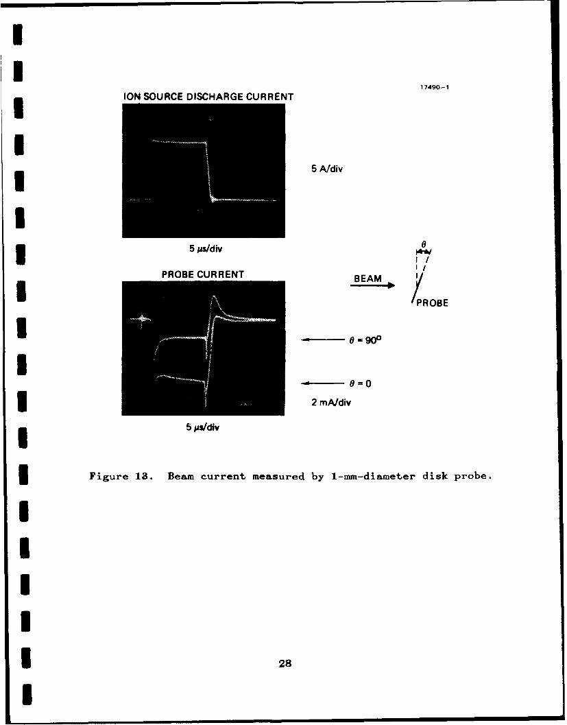
background plasma contribution to the beam-probe current. A beam
U profile measured by slowly scanning the probe across the beam
g channel is shown in Figure 14. A rather narrow well-collimated,
7-mm-diameter (FWHM) beam was found at 67 kV and 3 A of cathode
3 current.
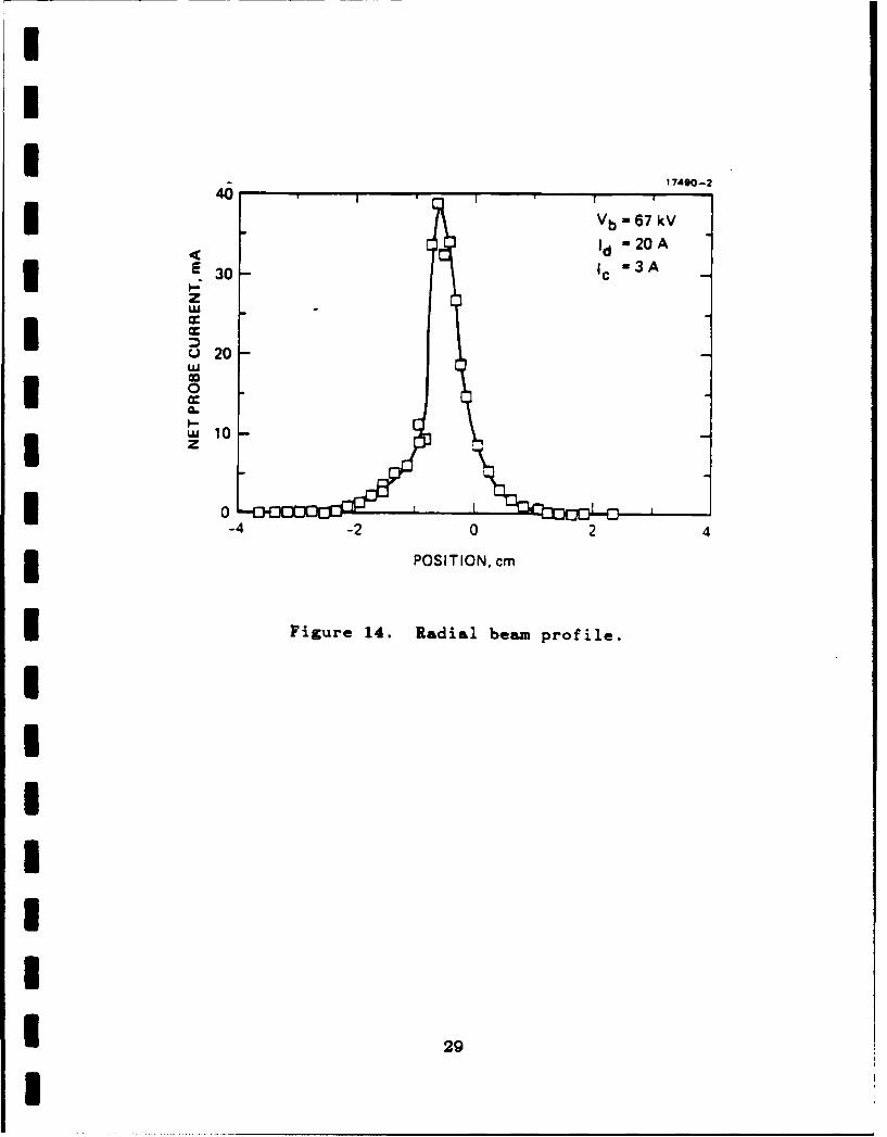
The beam profile was found to be consistent with beam
U collimation via ion focusing and the Bennett-pinch effect. As
the E-beam propagates through the background helium gas, a
tenuous plasma is generated by electron-neutral collisions. Ions
3 in this plasma neutralize the space-charge in the beam and allow
it to propagate free of space-charge blow-up effects. However,
3 rather than simply drifting in a ballistic manner, the beam is
also subject to the magnetic "pinch" force from the poloidal
magnetic field produced by the beam current. This force will
3 constrict the beam channel if the magnetic-field pressure exceeds
the transverse thermal beam pressure as shown schematically in
3 Figure 15. This phenomena is known as the Bennett-pinch effect.8
Quantitatively, the pinch condition may be expressed as
3 B2-R > n T (7)8W - b
!2
U ~ION SOURCE DISCHARGE CURRENT179-
- 5 A/div
5 asdiv
IPROBE CURRENT BEAM /RB
I 2 mAldiv
5 lMs/div
Figure 18. Beam current measured by 1-mm-diameter disk probe.
I 28
1 417490-2
'1 b - 67 kV
'-20 A
30 Ic 3A
z
* 0
0
I z
3 0-4 -2 0 2 43 POSITION, cm
3Figure 14. Radial beam profile.
I2
17490-8
I E -GU NANODEAPERTURE Bp
*x 0--I- ...........
3 Figure 15. Bennett-pinch effect.
I3
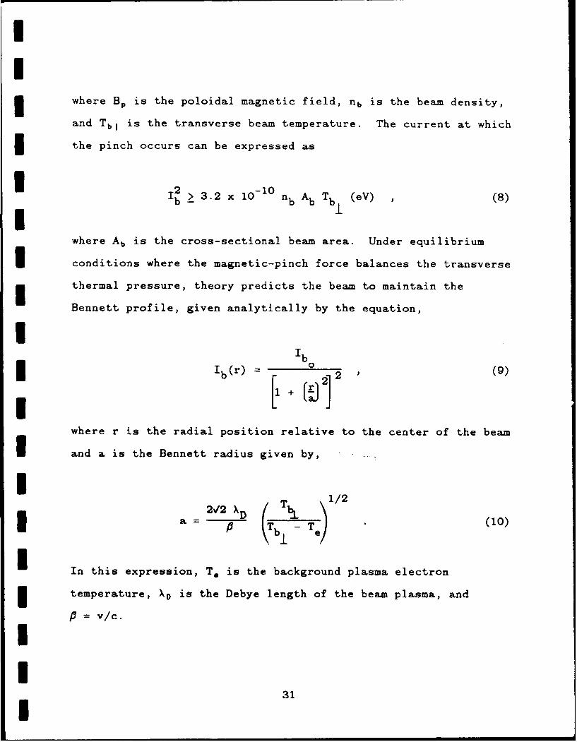
UI3 where BP is the poloidal magnetic field, nb is the beam density,
and TbjI is the transverse beam temperature. The current at which
* the pinch occurs can be expressed as
I2 > 32 x10 - 1 0 nb AbT (eV) (8)
where Ab is the cross-sectional beam area. Under equilibrium
I conditions where the magnetic-pinch force balances the transverse
thermal pressure, theory predicts the beam to maintain the
Bennett profile, given analytically by the equation,
Ib
Ib(r) = 1 ()
where r is the radial position relative to the center of the beam
I and a is the Bennett radius given by,
2,2 X T 1/2
a 16 T Te ) (10)
In this expression, To is the background plasma electron
temperature, XD is the Debye length of the beam plasma, and
S= v/c.
I
31I
I
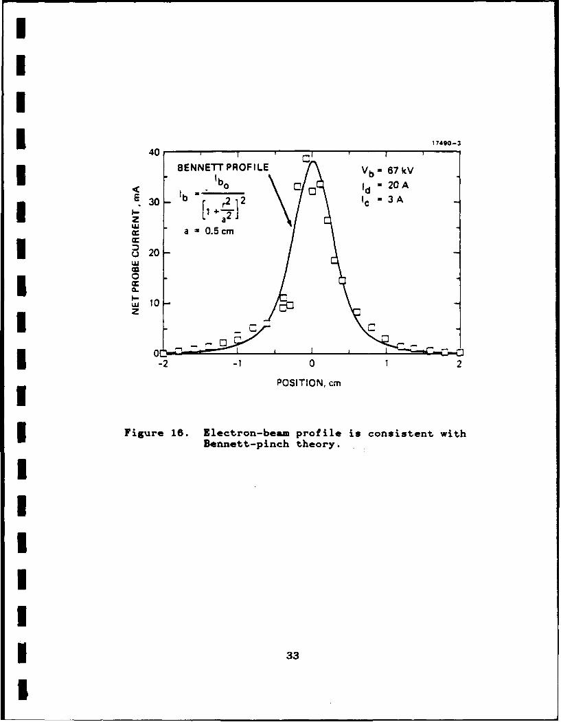
U Figure 16 shows a fit comparison of the measured profile at
2.1 A of actual beam current with a curve which corresponds to
the Bennett-profile theory. The data points correspond quite
* well to the Bennett-pinch prediction for a Bennett radius of a =
0.5 cm. Using the measured beam parameters (Vb = 67 kV, Ib =
I2.1 A, nb = 1.1X10 9 cm-3 and Ab = 0.8 cm2 ) and the Bennett radius
from the curve fit in Figure 16, we can calculate the transverse
beam temperature from Eq. (10). The result is Tb 1 = 15 eV which
* is in rough agreement with the result from the "beam-slit
shadowgraph" diagnostic discussed in the next section.
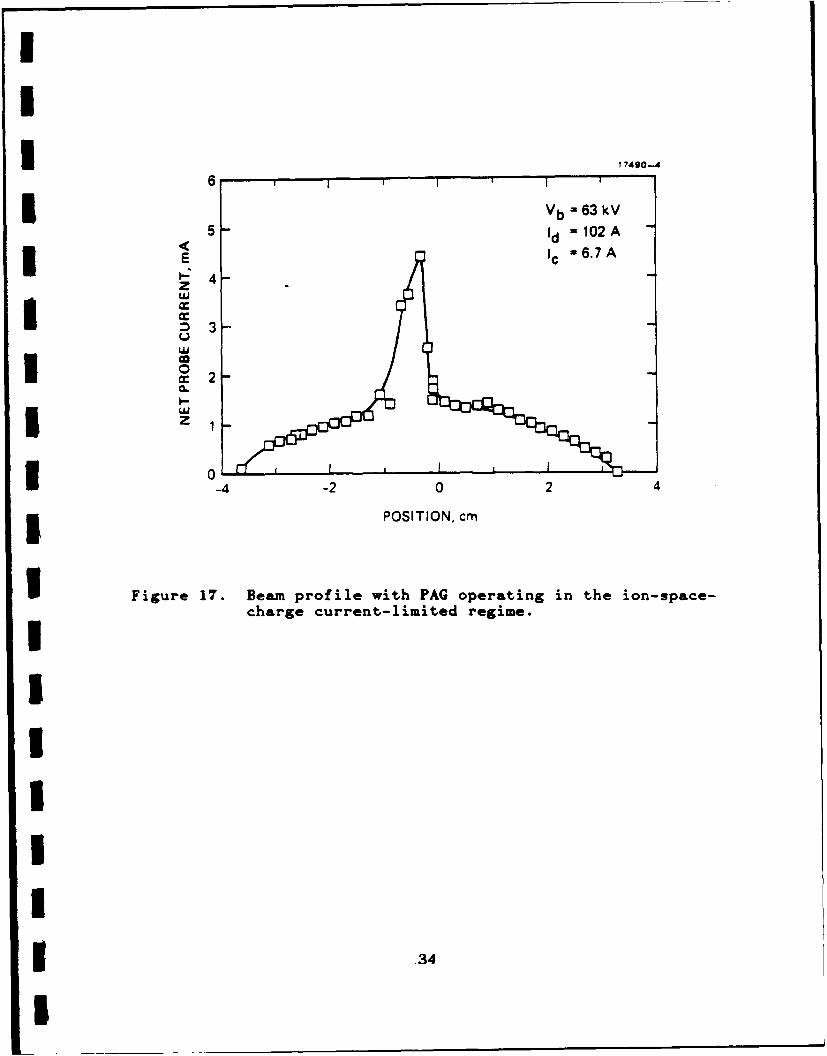
I When the ion-source discharge uirrent is increased to values
where the ion current becomes space-charge limited, the beam
profile broadens significantly. Figure 17 shows such a profile
where the discharge current was set to 102 A at a beam voltage of
63 kV. The 7-mm-diameter on-axis beam is still observed, but now
U broad wings are also obtained which extend many centimeters
around the central peak. We believe the wings are generated by
the defocusing of the beam by the high ion-space-charge levels
* near the anode as described earlier.
I 2.2.5 Direct Beam-Temperature Diagnostic
Cold, high-brightness, low-divergence beams are required for
driving advanced systems such as free-electron lasers, E-beam
weapons, and excimer lasers. An important parameter which
quantifies the quality of an electron beam is the transverse
temperature. To accurately determine this beam parameter in the
PAG, we have designed a "beam-slit shadowgraph".
32
III
40 17490-3
BENNETT PROF ILE Vb 67 kV
bo /Cb d 20 A
30 Ib C 2
3A
I- a2a 0.5cm
I °2G 0
UU 10z
Iob - I I I 2
-2 01 2POSITION, cm
I Figure 16. glectron-beam profile is consistent with
Bennett-pinch theory.
IU
II 33
IU
1 17490-4
6 * I
I Vb - 63 kV
5 I 'd - 102 A
3
I =o2
0
I w,
3 0-4 -2 0 2 4
3 POSITION, cm
I Figure 17. Beam profile with FAG operating in the ion-space-
charge current-limited regime.
UIIIII* ,34
I
I
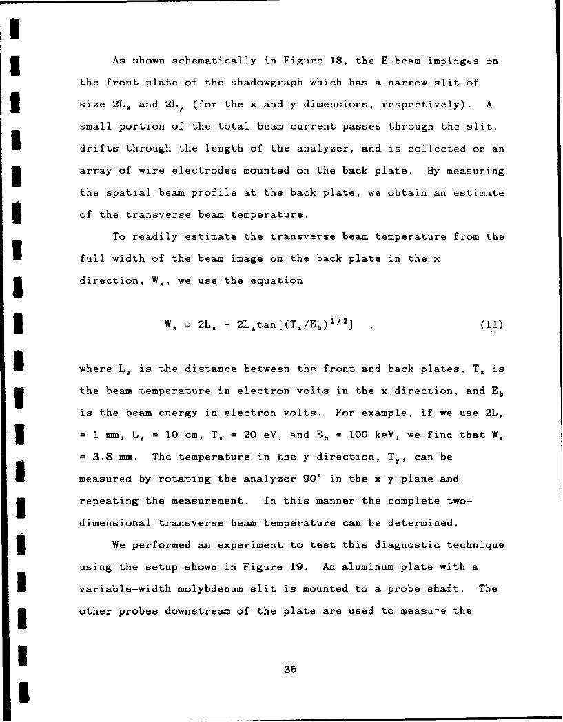
5 As shown schematically in Figure 18, the E-beam impinges on
the front plate of the shadowgraph which has a narrow slit of
I size 2L X and 2LY (for the x and y dimensions, respectively). A
small portion of the total beam current passes through the slit,
drifts through the length of the analyzer, and is collected on an
3 array of wire electrodes mounted on the back plate. By measuring
the spatial beam profile at the back plate, we obtain an estimate
5 of the transverse beam temperature.
To readily estimate the transverse beam temperature from the
I full width of the beam image on the back plate in the x
5 direction, W., we use the equation
3 WX = 2L X + 2LZtan[(T./Eb)'/' ] (11)
I where L. is the distance between the front and back plates, T. is
the beam temperature in electron volts in the x direction, and Eb
is the beam energy in electron volts. For example, if we use 2L.
I = mm, L Z =10 cm, TX = 20 eV, and Eb = 100 keV, we find that W.
= 3.8 mm. The temperature in the y-direction, TY, can be
measured by rotating the analyzer 90. in the x-y plane and
3 repeating the measurement. In this manner the complete two-
dimensional transverse beam temperature can be determined.
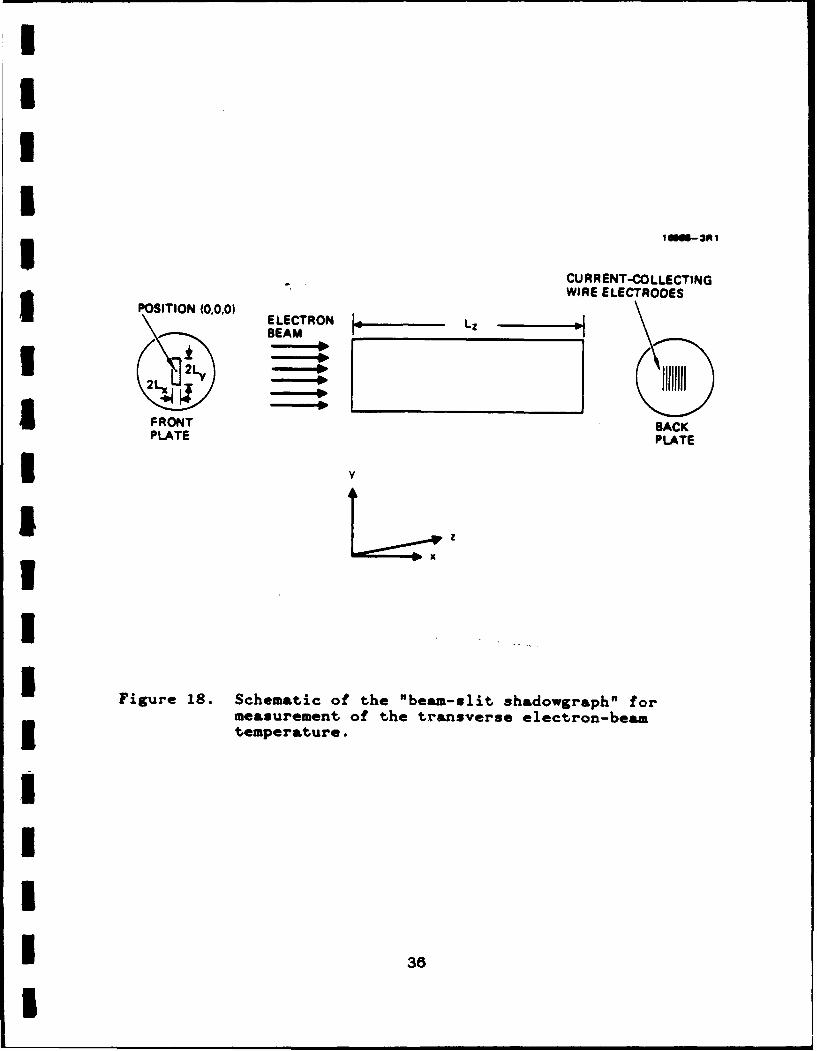
5 We performed an experiment to test this diagnostic technique
using the setup shown in Figure 19. An aluminum plate with a
I variable-width molybdenum slit is mounted to a probe shaft. The
5 other probes downstream of the plate are used to measu-e the
1 35I
I3II
10009-30t I
CURRENT-COLLECTING
WIRE ELECTRODES5POSITION (00,0) E LECTRON VZBEAM L
2L _ _ _ _ _ _
FRONT SACKPLATE PLATE
3vI
I
Figure 18. Schematic of the "beam-slit shadowgr&ph" formeasurement of the transverse electron-beam
I temperature.
IIII 36
I
WIRE-ANODE 17490-7 PM
CTOEDISCHARGE FARADAYE-EMSLIT CUP
HVEBE *r
1FJ.CUP
I IcGRIDTU RBOPUMP
0.1 ;s +1kVLANGMUIRI PROBEXTR N-3ARRAY3 SWITCH
Figure 1g. Schematic of the 120-kY PAG scaling experiment withI a "beam-slit shadowgraph." The beam slit is located
just upstream of the Langmuir-probe array.
* 37
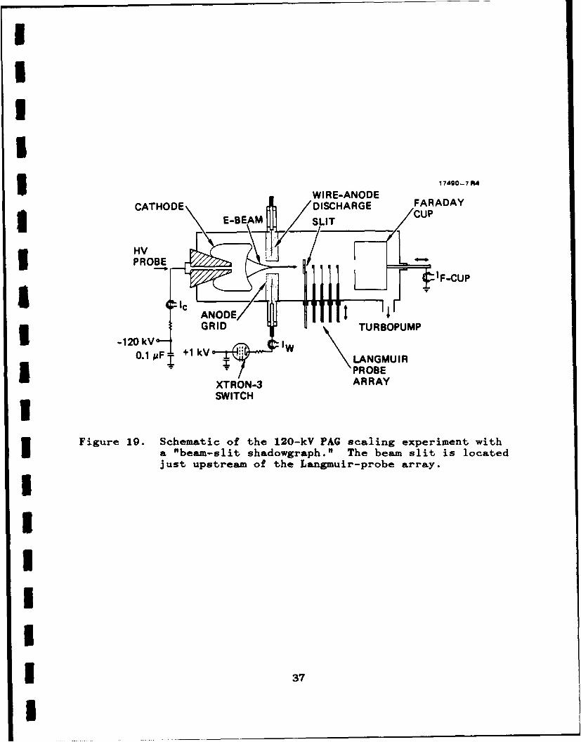
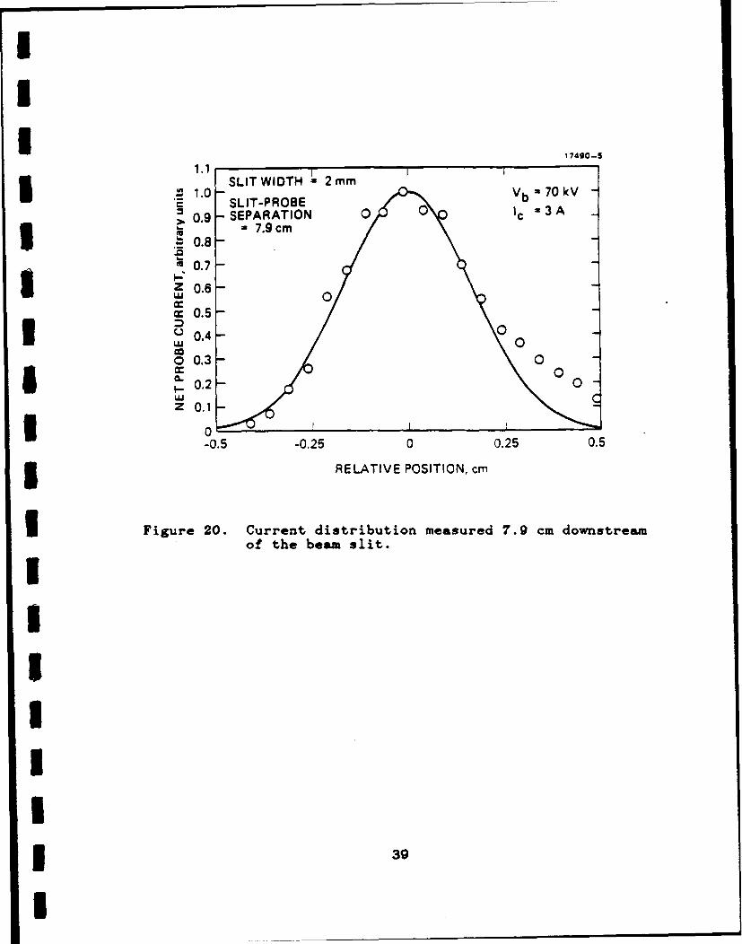
Icurrent distribution at different distances from the plate. The
measured current distribution using a 2-mm-wide slit and a 70-kV,
2.5-A beam is shown in Figure 20. Using the simplified analysis
represented by Eq. (11) to estimate the transverse beam
3 temperature we obtain a value of TbL = 14 eV - consistent with
the result that was obtained from the Bennett-profile fit.
3UaUIIIIIIII1 38
I
I
I I 17490-5
4 .0- SIWIT 2mmV b -=70 kV -10SLIT-PROBE
>0.9 - SEPARATION 0 Ic = 3A ", = 7.9 cm
S0.8-0.7 -
z 0.6-
-0.5-(J0.4-
0 0.3- 00CL 0.2- 0z 0.1
-0.5 -0.25 0 0.25 0.5
3RELATIVE POSITION, cm
U Figure 20. Current distribution measured 7.9 cm downstreamof the beam slit.
II!UII
I
I5 SECTION 8
HOLLOW-CATHODE-PLASMA E-GUN EXPERIMENTS
I Because of the electron-beam current density limitations in
the PAG that were discussed in the previous section, we searched
for a modified cold-cathode E-gun configuration that would
1 provide significantly higher current density. Under our separate
IR&D project on Pulsed Power Switches for Military Systems we
3 rediscovered Hughes plasma-cathode E-gun9 which was originally
invented and developed by R.C. Knechtli as a low current-density
(<1 A/cm2 ) rectangular cross-section gun for driving
5 gas-discharge lasers. Plasma cathodes usually have
plasma-boundary stability problems, but Hughes plasma E-gun
3 exploited a hollow-cathode discharge to gridded electrode that
served as a stabilizing structure as long as the discharge
current to the grid was maintained below the electron-beam
* space-charge-limited current in the accelerating gap.
Under our IR&D project we modified the plasma cathode E-gun
5 to operate at current density up to 40 A/cm 2 in a circular rather
than rectangular cross-section configuration in order to exploit
its capabilities to drive microwave generators. With the consent
3 of the Air Force, we then adapted the new gun configuration to
the requirements of our parallel Plasma Three-Wave-Mixing Program
* (Air Force Office of Scientific Research Contract
No. F49620-85-C-0059) under the present PAG contract. The
I Three-Wave-Mixing program was previously using planar PAG guns
5 and millimeter-wave power scaling experiments with beam current
3 40I
I3 were limited to only 7 A of total injected beam current. The
adapted plasma-cathode guns have enabled the E-gun current to
3 reach the 100-A level at 30-kV of beam voltage as described
below.
3 3.1 HOLLOW-CATHODE-PLASMA (HCP) E-GUN CONFIGURATION
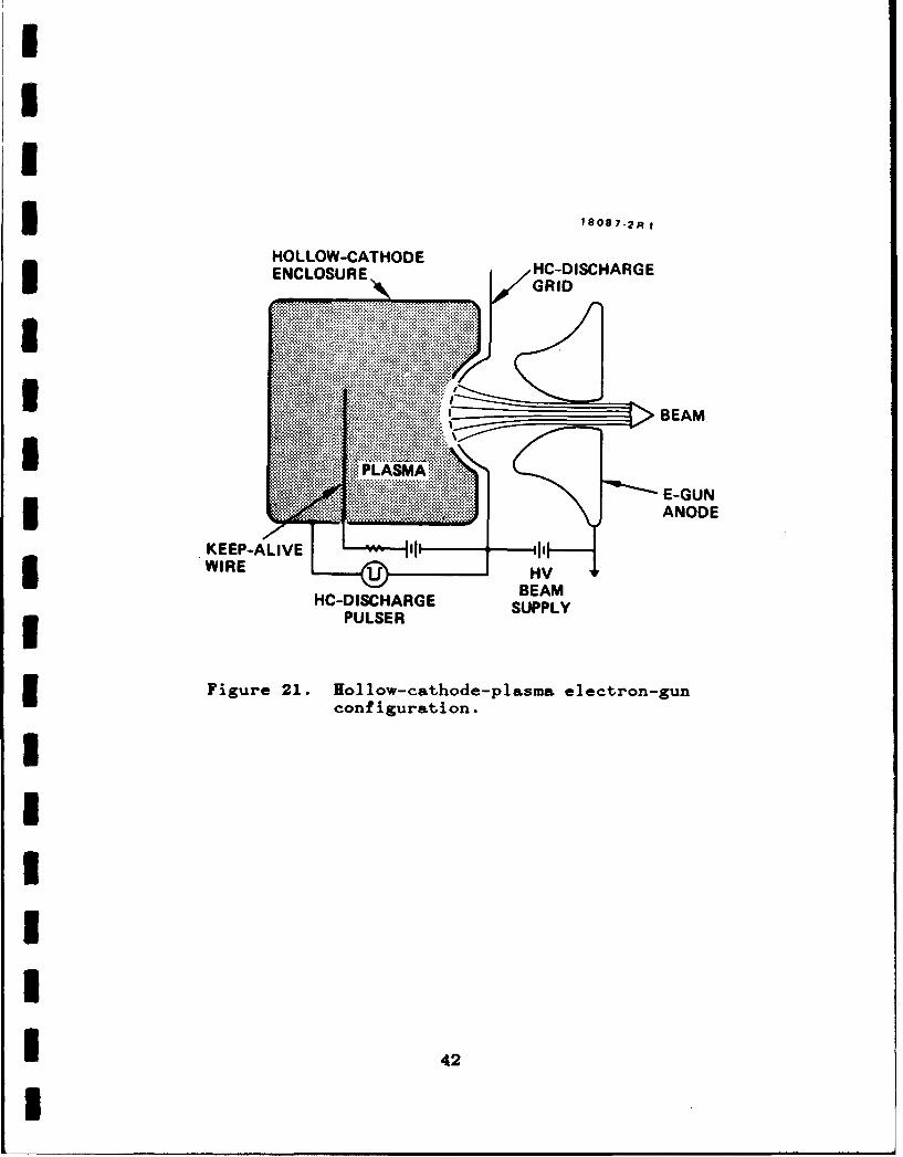
The new high-current cold-cathode device is called the
3 Hollow-Cathode-Plasma or HCP E-gun because it exploits a
low-pressure glow discharge inside a hollow-cathode (HC)
enclosure as shown in Figure 21 to generate a stable high-density
5 plasma from which a high-current-density E-beam can be extracted.
The enclosure is filled with 5 to 100 mTorr of helium gas which
3 is ionized in a low current (100 mA) keep-alive discharge to a
fine-wire anode by a 2-kV power supply as shown in the Figure.
I The keep-alive plasma provides for low jitter ignition of the
* high-current discharge which is struck between the hollow cathode
and the HC-discharge grid that is located just outside the HC
5 aperture.
The HC configuration with large cathode-to-anode area ratio
I provides efficient confinement of ionizing electrons inside the
g HC, and thus enables high-density plasma generation at low gas
pressures. The HC plasma is modulated by applying a negative
3 pulse to the HC relative to the anode grid with the HC-discharge
pulser, as shown. The HC-discharge grid has a high optical
3 transparency (~62%), yet ultrasmall apertures (-250 pm diameter).
The high-density plasma (n. - 3x1O 12/cm3 at 60 A/cm 2 current
I 41I
3 1808 7 -2R I
HOLLOW-CATHODE H-ICAGENCLOSURE V GC-DSCAG
MA:PLASMA.1 ... W.E-GUN
*VV,.... ANODE
KEEP-ALIVE H I--IWIRE L H
HC DISCHARGE SUPPLPULSER SPL
Figure 21. lollow-cathode-plasma electron-gun
configuration.
I 42
3 density) behind the anode-sheath at this grid provides the
high-current-density electron emission in the HCP gun. Electrons
3 are extracted from the plasma and accelerated to high energy by
applying a high positive potential to the electron-gun anode
electrode, which is located to the right of the HO-discharge grid
3 in Figure 21. The beam is electrostatically focused through the
aperture in the anode to form a high-current-density,
3 circular-cross-section beam. The plasma surface behind the
HC-discharge grid remains stable for arbitrary pulse lengths as
long as the HO-discharge current does not exceed the
3 space-charge-limited E-beam current in the accelerating gap. The
beam current may be controlled in a linear manner by simply
3 adjusting the current provided by the HC discharge pulser. For
high transparency HC-discharge grids, the E-beam to HC-discharge
current ratio is nearly one to one.
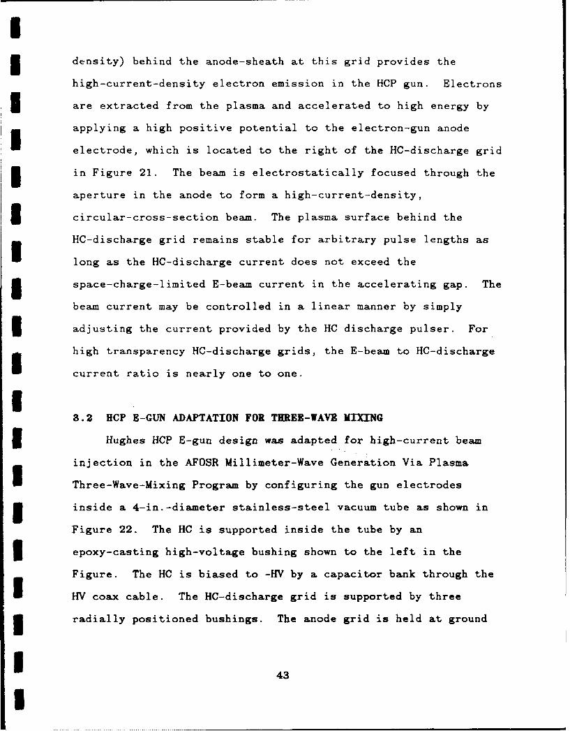
3.2 HCP E-GUN ADAPTATION FOR THREE-WAVE MIXING
Hughes HCP E-gun design was adapted for high-current beam
injection in the AFOSR Millimeter-Wave Generation Via Plasma
U Three-Wave-Mixing Program by configuring the gun electrodes
3 inside a 4-in.-diameter stainless-steel vacuum tube as shown in
Figure 22. The HC is supported inside the tube by an
* epoxy-casting high-voltage bushing shown to the left in the
Figure. The HC is biased to -HIV by a capacitor bank through the
HV coax cable. The HC-discharge grid is supported by three
3 radially positioned bushings. The anode grid is held at ground
1 43U

~~~HOLLOW C142A
EPOXY CASTING GRTHDESHN3HIGH-VOLTAGE G I U HN - - - -,
ANODE GRID
1 3.8 cm
IDI
IITURBOMOLECULAR ACCELERATING3 PUMPHOLLOW
CATHODE
Figure 22. Experimental set-up for testing theg high-current RCP E-gun.
I 44
3 potential. This grid also serves as the terminating grid of the
3.8-cm-diameter plasma-filled waveguide cavity into which the
3 beam is injected. The E-beam diameter is defined by the
2.5-cm-diameter aperture in the HC-discharge grid.
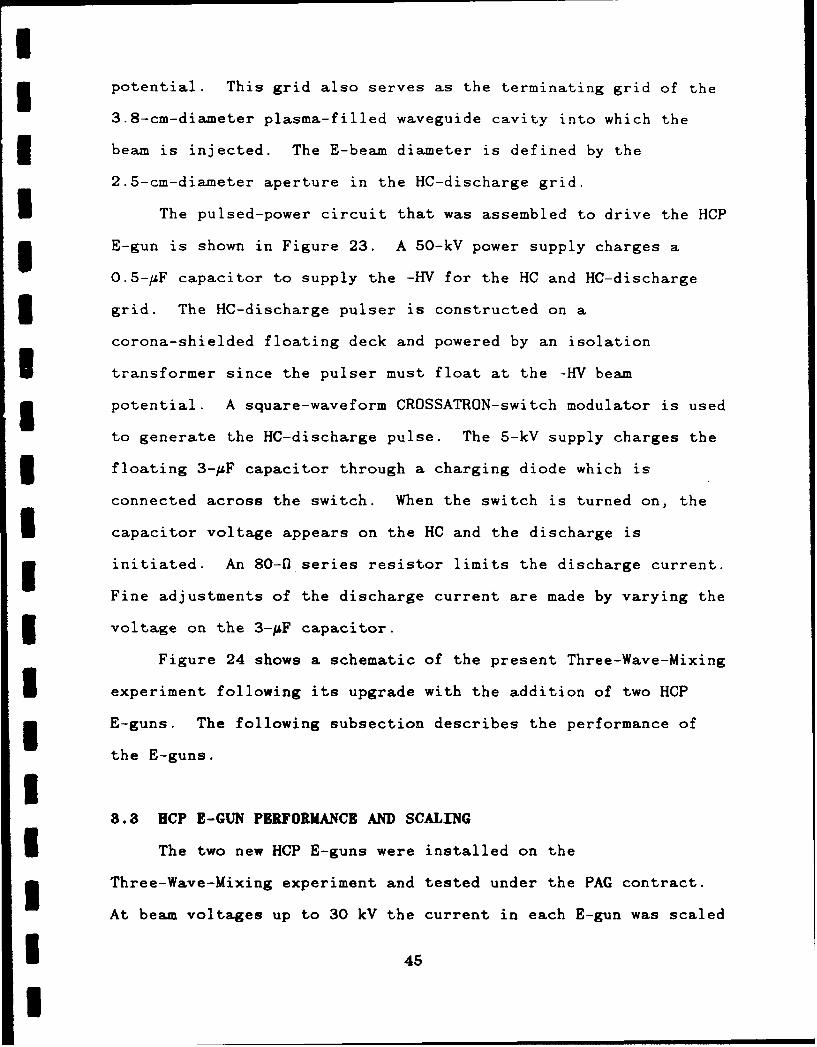
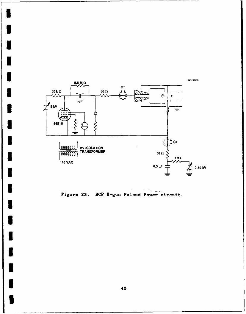
n The pulsed-power circuit that was assembled to drive the HCP
E-gun is shown in Figure 23. A 50-kV power supply charges a
0.5-1F capacitor to supply the -HV for the HC and HC-discharge
3 grid. The HC-discharge pulser is constructed on a
corona-shielded floating deck and powered by an isolation
I transformer since the pulser must float at the -HV beam
5 potential. A square-waveform CROSSATRON-switch modulator is used
to generate the HC-discharge pulse. The 5-kV supply charges the
3 floating 3-/SF capacitor through a charging diode which is
connected across the switch. When the switch is turned on, the
* capacitor voltage appears on the HC and the discharge is
initiated. An 80- series resistor limits the discharge current.
Fine adjustments of the discharge current are made by varying the
3 voltage on the 3-,uF capacitor.
Figure 24 shows a schematic of the present Three-Wave-Mixing
3 experiment following its upgrade with the addition of two HCP
5 E-guns. The following subsection describes the performance of
the E-guns.I8.8 HCP E-GUN PERFORMANCE AND SCALING
I The two new HCP E-guns were installed on the
3 Three-Wave-Mixing experiment and tested under the PAG contract.
At beam voltages up to 30 kV the current in each E-gun was scaled
1 45
I
8.I50kI80Q C
5 84511
3 i i CT!.E A M HV ISOLATION
C110 VAC
0. f0-50 WV
Figure 23. BCP K-gun Pulsed-Power circuit.
1 46
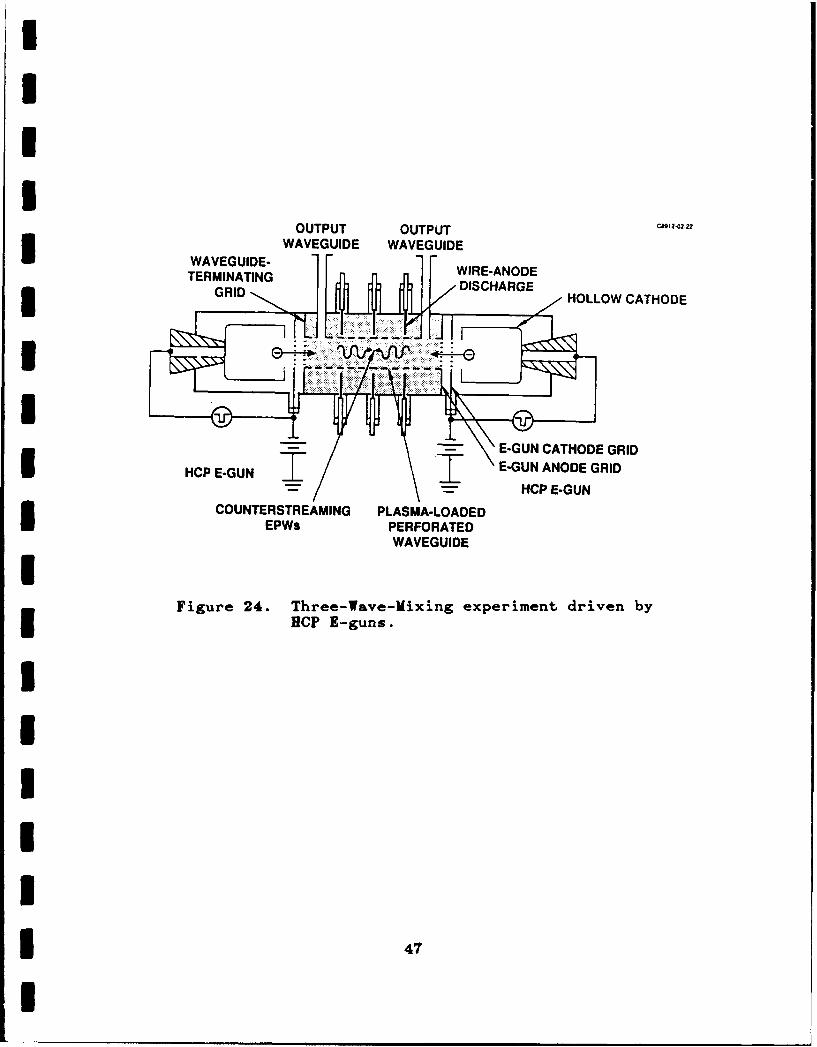
OUTPUT OUTPUT C8012-02-22
WAVGUIE-WAVEGUIDE WAVEGUIDE
TERMINATING W ISC-AARGEGRDDSCAG HOLLOW CATHODE
II
ILE-GUN CATHODE GRID3C -U E-GUN ANODE GRID
- IICPE-GUNCOUNTERSTREAMING PLASMA-LOADEDIEPWS PERFORATED
WAVEGUIDE
Figure 24. Three-Wave-Mixing experiment driven byNCP B-guns.
I4
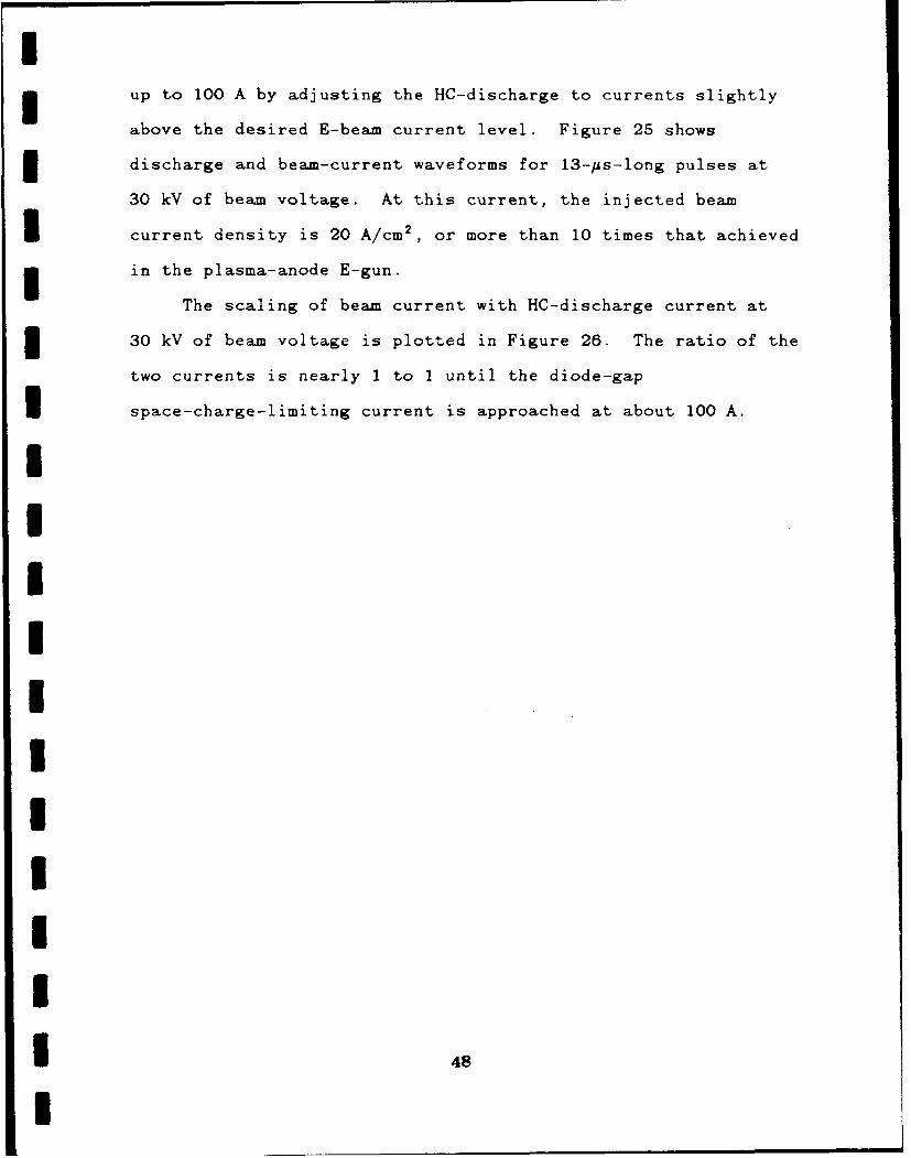
I3 up to 100 A by adjusting the HC-discharge to currents slightly
above the desired E-beam current level. Figure 25 shows
3 discharge and beam-current waveforms for 13-ps-long pulses at
30 kV of beam voltage. At this current, the injected beam
I current density is 20 A/cm2 , or more than 10 times that achieved
3 in the plasma-anode E-gun.
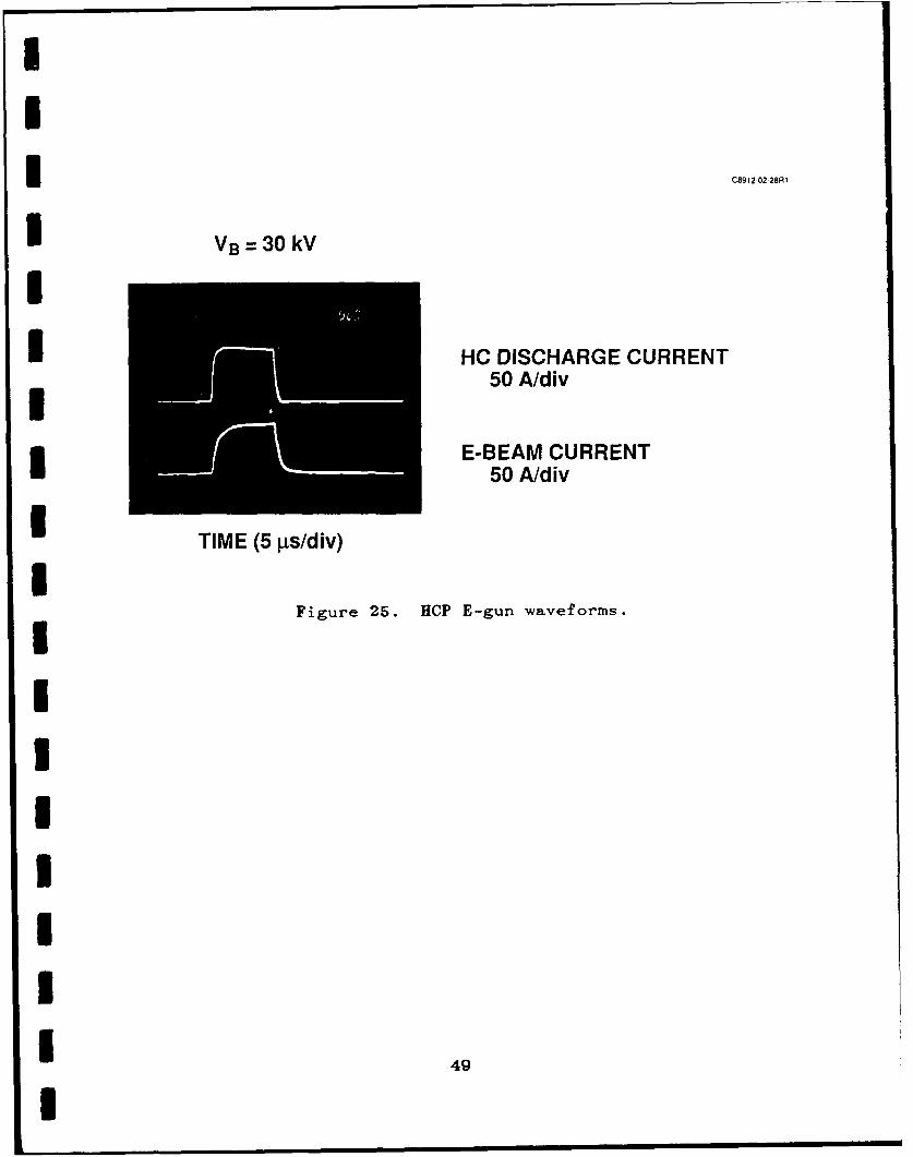
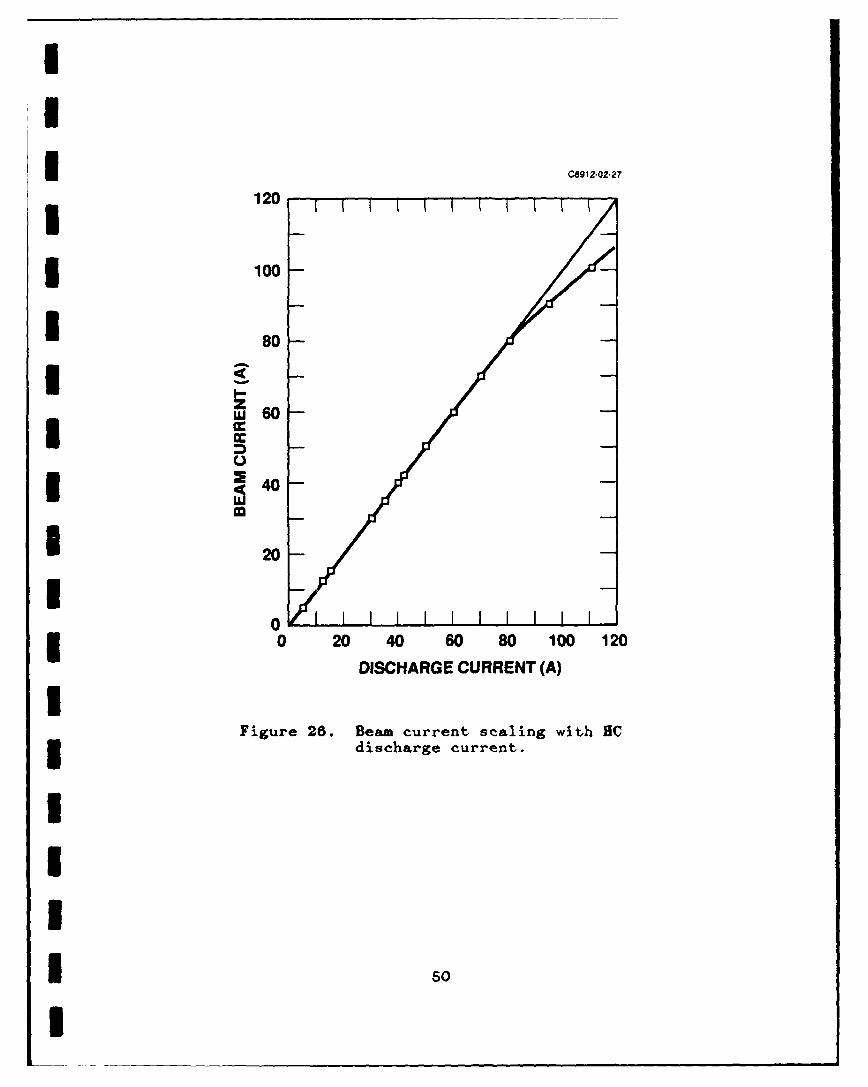
The scaling of beam current with HC-discharge current at
3 30 kV of beam voltage is plotted in Figure 26. The ratio of the
two currents is nearly I to I until the diode-gap
Ispace-charge-limiting current is approached at about 100 A.
4I£IIII3II'
I 4
C8g12 02-28R I
I VB =30kV
I HC DISCHARGE CURRENT50 A/div
E-BEAM CURRENTI 50 A/div
I TIME (5 jts/div)
Figure 25. HOP E-gun waveforms.
I4
UI
I C8912-02-27
120
* 100
* 80
IZ
m
II
460
0
Figure 26. Beam current scaling with HCI discharge current.
Iso
I
I
I3 SECTION 4
INTERACTIONS
1 A. The following paper was presented at the 1986 American
* Physical Society Plasma Physics Division Meeting in
Baltimore, Maryland on 8 November 1986.I"Plasma-Anode E-Gun," by A.J. Palmer, R.J. Harvey,
R.W. Schumacher, F.A. Dolezal, D.J. Gregoire, and
3 J. Santoru.
IB. The following paper was presented at the IEEE Tnternational
Conference on Plasma Science on 2 June 1987 in Arlington-
3 Virginia.
"Plasma-Anode e-Gun," by J. Santoru, R.W. Sc'humaher,
A.J. Palmer, R.J. Harvey, F.A. Dolezal, and D.J Gregoire.
UC. A seminar on the PAG was given at the Naval Research
Laboratory in Washington, D.C., on 5 December 1986.
IIII 51
U
ID. The following paper was presented at the 1987 APS Division
of Plasma Physics Meeting on 2 November 1987 in San Diego,
California.
I "Plasma-Anode Electron Gun (PAG) Scaling," by J. Santoru,
R.W. Schumacher, R.J. Harvey, and A.J. Palmer.
IE. The following paper was presented at the 1989 IEEE
Conference on Plasma Science on 24 May 1989 in Buffalo, New
* York.
* "Millimeter-Wave Radiation Generated Via Plasma Three-Wave
Mixing Using High-Current Density Counterstreaming Electron
I Beams," by J. Santoru and R.W. Schumacher.
IIo
IIIIII 52
I
I3 SECTION 5
PUBLICATIONSI"Plasma-Anode Electron Gun," to be submitted to Journal of
I Applied Physics
IIIIIIIIIIIIUI 53
I
ISECTION 6
RESEARCH PERSONNEL
The following personnel at Hughes Research Laboratories are
associated with the research effort:I1. Robert W. Schumacher (Principal Investigator)
Project Manager (213) 317-5439
2. Joseph SantoruMember of the Technical Staff (213) 317-5838
3. Allan J. PalmerMember of the Technical Staff (213) 317-5710
4. Ronnie M. WatkinsDevelopment Engineer, Specialist (213) 317-5424
5. Robin J. HarveySenior Scientist (213) 317-5236
IIIIIIIII 54
I
IREFERENCES
1. W.B. Herrmannsfeldt, SLAC Report No. 226, November 1979.
2. R.J. Harvey, "Plasma-Anode Electron Gun," Hughes AircraftCompany patent disclosure No. 84050, U.S. patent pending.
U 3. J.R. Pierce, Theory and Design of Electron Beams, 2nd Ed.,Van Nostrand, New York, 1954.
4. G.W. McClure, "Low-Pressure Glow Discharge," Appl. Phys.Lett. 2, No. 12, 233 (1963).
5. J.R. Bayless and R.J. Harvey, "Continuous Ionization Injectorfor Low-Pressure Gas-Discharge Device," U.S. Pat. No. 3, 949,260 (1976) [Assigned to Hughes Aircraft Company].
6. P.F. Little, "Secondary Effects," Band XXI, Vol. XXI,Handbook der Physics (1956). Also see A.G. Hill et al.,3 Phys. Rev. 55, 463-470, March 1939.
7. H.E. Gallagher and R.J. Harvey, "Development of 1-GW ElectronBeam Controlled Switch," IEEE Conf. Record 1984 Sixteenth3 Power Modulator Symposium, June 1984, p. 158.
8. W.H. Bennett, Phys. Rev. 45, 890 (1934); also see N.A. Kralland A.W. Trivelpiece, "Principles of Plasma Physics," p. 495,McGraw Hill, New York (1973).
9. R.C. Knechtli, U.S. Patent No. 3,831,052 (1974).
IIIIIII 55
I