kvaser memorator user’s guidekvaser memorator user’s guide 5 (29) 1about this manual this manual...
TRANSCRIPT
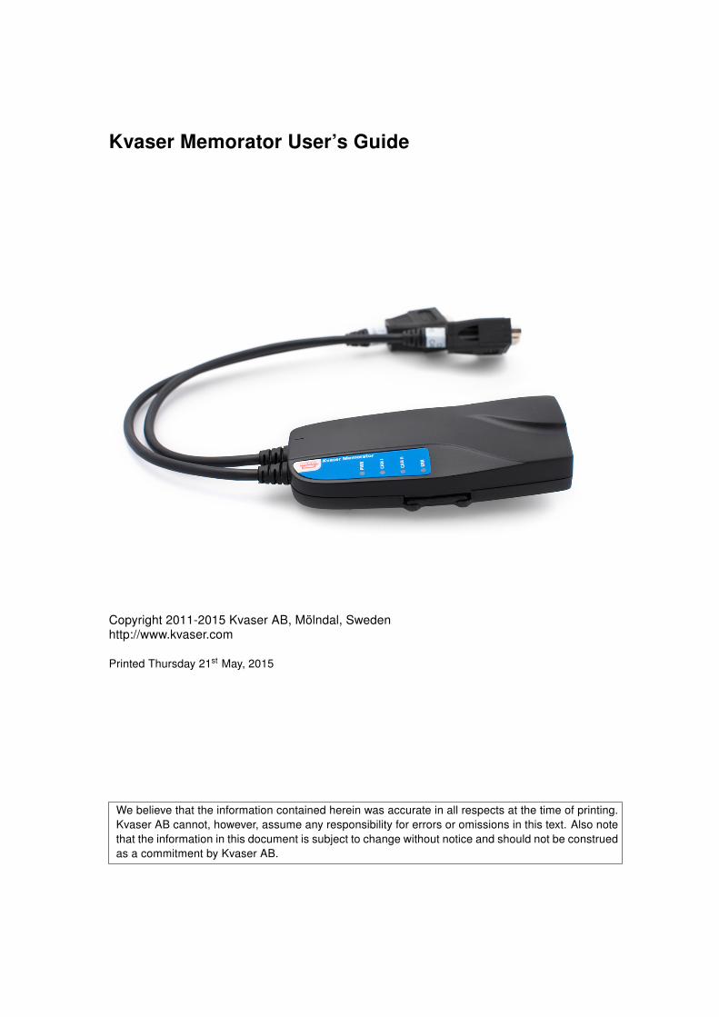
Kvaser Memorator User’s Guide
Copyright 2011-2015 Kvaser AB, Mölndal, Swedenhttp://www.kvaser.com
Printed Thursday 21st May, 2015
We believe that the information contained herein was accurate in all respects at the time of printing.Kvaser AB cannot, however, assume any responsibility for errors or omissions in this text. Also notethat the information in this document is subject to change without notice and should not be construedas a commitment by Kvaser AB.

Kvaser Memorator User’s Guide 2 (29)
(This page is intentionally left blank.)
Kvaser AB, Mölndal, Sweden — www.kvaser.com
Kvaser Memorator User’s Guide 3 (29)
Contents
1 About this manual 5
2 Introduction 62.1 Kvaser Memorator . . . . . . . . . . . . . . . . . . . . . . . . . . . . 62.2 Triggers . . . . . . . . . . . . . . . . . . . . . . . . . . . . . . . . . 62.3 Filters . . . . . . . . . . . . . . . . . . . . . . . . . . . . . . . . . . 62.4 Memory cards . . . . . . . . . . . . . . . . . . . . . . . . . . . . . . 62.5 Configuration software in the PC (Kvaser Memorator Tools) . . . . . 72.6 Major features in Kvaser Memorator . . . . . . . . . . . . . . . . . . 7
3 Kvaser Memorator hardware 83.1 Hardware installation . . . . . . . . . . . . . . . . . . . . . . . . . . 83.2 CAN Channels . . . . . . . . . . . . . . . . . . . . . . . . . . . . . . 83.3 Power supply . . . . . . . . . . . . . . . . . . . . . . . . . . . . . . 93.4 Flash disks . . . . . . . . . . . . . . . . . . . . . . . . . . . . . . . . 93.5 LED indicators . . . . . . . . . . . . . . . . . . . . . . . . . . . . . . 103.6 External trigger . . . . . . . . . . . . . . . . . . . . . . . . . . . . . 12
4 How to use Kvaser Memorator 144.1 The different run modes . . . . . . . . . . . . . . . . . . . . . . . . . 144.2 How to disconnect Kvaser Memorator from a CAN system . . . . . . 144.3 Kvaser Memorator Tools . . . . . . . . . . . . . . . . . . . . . . . . 154.4 Disk management . . . . . . . . . . . . . . . . . . . . . . . . . . . . 164.5 Troubleshooting . . . . . . . . . . . . . . . . . . . . . . . . . . . . . 16
5 Appendices 185.1 Technical data . . . . . . . . . . . . . . . . . . . . . . . . . . . . . . 185.2 Disk capacity . . . . . . . . . . . . . . . . . . . . . . . . . . . . . . 185.3 Disk structure . . . . . . . . . . . . . . . . . . . . . . . . . . . . . . 195.4 CAN Channel Transceivers . . . . . . . . . . . . . . . . . . . . . . . 205.5 Technical Data for LS Option . . . . . . . . . . . . . . . . . . . . . . 225.6 Technical Data for SWC Option . . . . . . . . . . . . . . . . . . . . . 225.7 Updating the firmware . . . . . . . . . . . . . . . . . . . . . . . . . . 225.8 Overrun . . . . . . . . . . . . . . . . . . . . . . . . . . . . . . . . . 23
6 Frequently Asked Questions 24
7 Disposal and Recycling Information 25
8 Legal acknowledgements 268.1 Usage warning . . . . . . . . . . . . . . . . . . . . . . . . . . . . . . 268.2 EC Regulatory Compliance . . . . . . . . . . . . . . . . . . . . . . . 278.3 About this manual . . . . . . . . . . . . . . . . . . . . . . . . . . . . 28
Kvaser AB, Mölndal, Sweden — www.kvaser.com
Kvaser Memorator User’s Guide 4 (29)
8.4 Patents, copyrights and trademarks . . . . . . . . . . . . . . . . . . 28
9 Document revision history 29
Kvaser AB, Mölndal, Sweden — www.kvaser.com

Kvaser Memorator User’s Guide 5 (29)
1 About this manual
This manual is intended for those who want to use Kvaser Memorator. It containsinformation about the hardware, instructions on how to connect it, and so on.
The software for Kvaser Memorator is called Kvaser Memorator Tools and isdescribed in detail in its online help.
Note: This manual assumes you are using firmware 2.5 or later.
Kvaser AB, Mölndal, Sweden — www.kvaser.com
Kvaser Memorator User’s Guide 6 (29)
2 Introduction
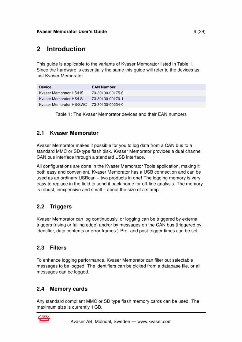
This guide is applicable to the variants of Kvaser Memorator listed in Table 1.Since the hardware is essentially the same this guide will refer to the devices asjust Kvaser Memorator.
Device EAN Number
Kvaser Memorator HS/HS 73-30130-00175-6
Kvaser Memorator HS/LS 73-30130-00170-1
Kvaser Memorator HS/SWC 73-30130-00234-0
Table 1: The Kvaser Memorator devices and their EAN numbers
2.1 Kvaser Memorator
Kvaser Memorator makes it possible for you to log data from a CAN bus to astandard MMC or SD-type flash disk. Kvaser Memorator provides a dual channelCAN bus interface through a standard USB interface.
All configurations are done in the Kvaser Memorator Tools application, making itboth easy and convenient. Kvaser Memorator has a USB connection and can beused as an ordinary USBcan – two products in one! The logging memory is veryeasy to replace in the field to send it back home for off-line analysis. The memoryis robust, inexpensive and small – about the size of a stamp.
2.2 Triggers
Kvaser Memorator can log continuously, or logging can be triggered by externaltriggers (rising or falling edge) and/or by messages on the CAN bus (triggered byidentifier, data contents or error frames.) Pre- and post-trigger times can be set.
2.3 Filters
To enhance logging performance, Kvaser Memorator can filter out selectablemessages to be logged. The identifiers can be picked from a database file, or allmessages can be logged.
2.4 Memory cards
Any standard compliant MMC or SD type flash memory cards can be used. Themaximum size is currently 1 GB.
Kvaser AB, Mölndal, Sweden — www.kvaser.com
Kvaser Memorator User’s Guide 7 (29)
2.5 Configuration software in the PC (Kvaser Memorator Tools)
• Configuration of the CAN controller – e.g. bit rate and filters
• Configuration of the trigger conditions
• Configuration of filter for messages to be stored
• The configuration is downloaded via USB
• Convert files logged in Kvaser Memorator to several different formats
2.6 Major features in Kvaser Memorator
• One device for desktop, laptop, and PDA (devices need a USB device port)
• Quick and easy plug-and-play installation
• Supports both 11-bit (CAN 2.0A) and 29-bit (CAN 2.0B active) identifiers
• CAN messages are time-stamped with 10 µs resolution
• Large on-board RAM buffer for CAN messages
• Supports “listen-only” mode for analyzing tools
• Driver support for major operating systems
• 100% compatible with applications written for Kvaser hardware such asLAPcan, PCIcan, and USBcan with Kvaser CANlib
• One MMC connector that accepts MMC or SD devices, with the size rangingfrom 32 MB up to 1 GB today and even larger to be expected in the future
• One CAN connection ISO11898-2 High speed, 50 kbit/s up to 1 Mbit/s(transceiver Philips TJA1050)
• A second CAN connection which can be either of
– LS: low-speed CAN - ISO11898-3
– HS: high-speed CAN - ISO11898-2
– SWC: single-wire CAN - J2411
• One USB 1.1 connection (12 Mbit/s). Can also be used in USB 2.0 slots
• Power from CAN-bus or from the USB side. Automatically switches powersupply between CAN (primary) and USB (secondary), to reduce power drainof laptop battery
• Built-in real time (calendar) clock with battery backup
• Logger status is indicated with four externally visible LEDs
Kvaser AB, Mölndal, Sweden — www.kvaser.com

Kvaser Memorator User’s Guide 8 (29)
3 Kvaser Memorator hardware
3.1 Hardware installation
The Kvaser Memorator device may be inserted in any free USB socket that ispresent on the host computer. You don’t have to switch the power off beforeinserting or removing the device.
For driver installation and firmware update, see the driver installationdocumentation.
3.2 CAN Channels
The standard Kvaser Memorator has two independent I/O ports (CAN channels)that are seen in Figure 1. In Figure 2 on Page 9, the first channel (channel 1) ismarked with “1”, whereas the second channel (number 2) is not marked. The CANconnectors are also labeled for easy identification.
Figure 1: Connections on Kvaser Memorator
Kvaser AB, Mölndal, Sweden — www.kvaser.com

Kvaser Memorator User’s Guide 9 (29)
Figure 2: The channels on Kvaser Kvaser Memorator (channel 2 is not marked)
3.3 Power supply
Kvaser Memorator can be powered both from the CAN side and from the USBside. To operate Kvaser Memorator in LOGGER mode, you must supply power onthe CAN side. To operate Kvaser Memorator in CONFIG or USBCAN mode, it issufficient to supply power from the USB side.
You supply power on the CAN side on CAN channel 1. Supplying power on CANchannel 2 is meaningless, but it will not hurt the device.
Use pin 9 for V+ and pin 3 for ground.
You can feed it with 8 V–40 V DC. The power requirement is around 1 W(maximum).
IMPORTANT: Kvaser Memorator HS/LS and HS/SWC must besupplied with both power on the CAN channel 1, as described,and a reference voltage on channel 2. The reference voltage istypically the battery or system voltage. The reference voltageinput does not draw any current.
3.4 Flash disks
You can use MultiMediaCard (MMC) and Secure Digital (SD) disks with yourKvaser Memorator.
The following disk sizes are supported and have been tested:
Kvaser AB, Mölndal, Sweden — www.kvaser.com
Kvaser Memorator User’s Guide 10 (29)
Type Size
MMC 32 MB, 64 MB
SD 32 MB, 64 MB, 128 MB, 256 MB, 512 MB, 1 GB
Table 2: Supported sizes
IMPORTANT: not all disks follow the MMC or SD standard. Whenin doubt, consult our web site for a list of recommended disktypes.
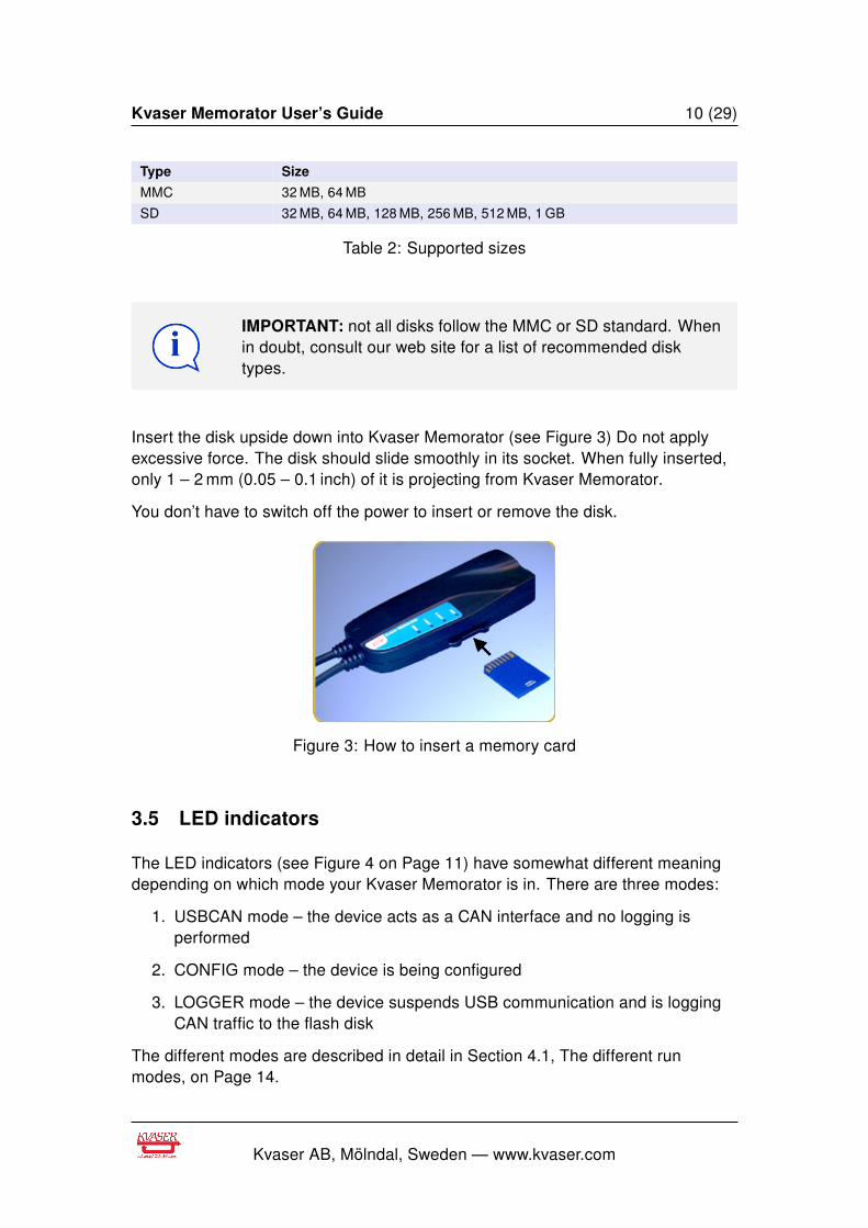
Insert the disk upside down into Kvaser Memorator (see Figure 3) Do not applyexcessive force. The disk should slide smoothly in its socket. When fully inserted,only 1 – 2 mm (0.05 – 0.1 inch) of it is projecting from Kvaser Memorator.
You don’t have to switch off the power to insert or remove the disk.
Figure 3: How to insert a memory card
3.5 LED indicators
The LED indicators (see Figure 4 on Page 11) have somewhat different meaningdepending on which mode your Kvaser Memorator is in. There are three modes:
1. USBCAN mode – the device acts as a CAN interface and no logging isperformed
2. CONFIG mode – the device is being configured
3. LOGGER mode – the device suspends USB communication and is loggingCAN traffic to the flash disk
The different modes are described in detail in Section 4.1, The different runmodes, on Page 14.
Kvaser AB, Mölndal, Sweden — www.kvaser.com
Kvaser Memorator User’s Guide 11 (29)
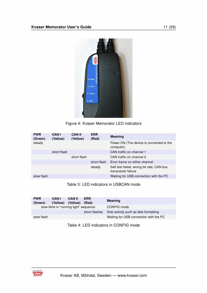
Figure 4: Kvaser Memorator LED indicators
PWR(Green)
CAN I(Yellow)
CAN II(Yellow)
ERR(Red)
Meaning
steady Power ON (The device is connected to thecomputer)
short flash CAN traffic on channel 1
short flash CAN traffic on channel 2
short flash Error frame on either channel
steady Self test failed, wrong bit rate, CAN bustransceiver failure
slow flash Waiting for USB connection with the PC
Table 3: LED indicators in USBCAN mode
PWR(Green)
CAN I(Yellow)
CAN II(Yellow)
ERR(Red)
Meaning
slow blink in “running light” sequence CONFIG mode
short flashes Disk activity such as disk formatting
slow flash Waiting for USB connection with the PC
Table 4: LED indicators in CONFIG mode
Kvaser AB, Mölndal, Sweden — www.kvaser.com
Kvaser Memorator User’s Guide 12 (29)
PWR(Green)
CAN I(Yellow)
CAN II(Yellow)
ERR(Red)
Meaning
all LEDs are flashing slowly Disk is missing or other fatal error
short flash CAN traffic on channel 1
short flash CAN traffic on channel 2
slow blink CAN 1 is error passive
slow blink CAN 2 is error passivetwo shortblinks
CAN 1 is bus off
two shortblinks
CAN 2 is bus off
short flash Error frame on either CAN channel
slow blink Logger mode, trigger passive
fast blink Logger mode, trigger active
slow blink Disk is full
fast blink Special disk activity, such as formatting, isin progress
long blink +short blink
Logger configuration is missing or corrupt
two shortblinks
Disk error
fast blink During scanning for the end of the loggerfile
Table 5: LED indicators in LOGGER mode
When removing the power supply for Kvaser Memorator duringlogging to disk, Kvaser Memorator has to close the still open diskfile when restarted. Closing a file involves scanning the file to findthe end it. During scanning the file to find the end, KvaserMemorator ERR (the red one) to indicate what is going on.
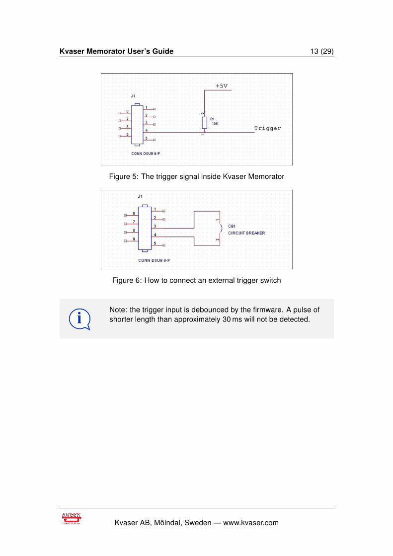
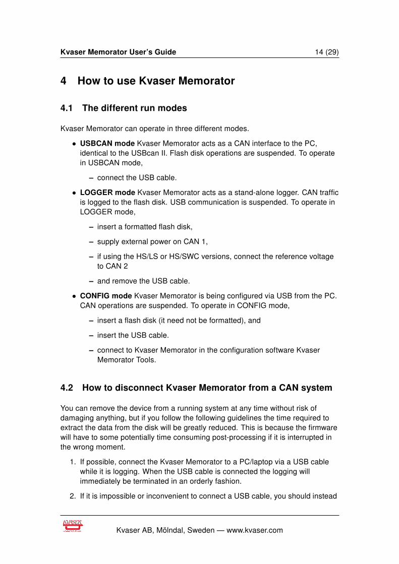
3.6 External trigger
Kvaser Memorator can be set up to trig on an external event. There are two waysto create such an external event:
• Connect a switch from pin 4 on CAN channel 1 to ground, which can befound on pin 3 on the same connector. See Figure 6 on Page 13.
• Connect a signal between 0 and 5 V to pin 4 on CAN channel 1.
Internally, pin 4 on CAN channel 1 has a pull-up to +5 V. See Figure 5 on Page 13.
If the external trigger is set to trig on falling edge the trigger is activated when thepin 4 is connected to ground and if trigger is set to trig on rising edge the trigger isactivated when the pin 4 is disconnected from ground.
Kvaser AB, Mölndal, Sweden — www.kvaser.com
Kvaser Memorator User’s Guide 13 (29)
Figure 5: The trigger signal inside Kvaser Memorator
Figure 6: How to connect an external trigger switch
Note: the trigger input is debounced by the firmware. A pulse ofshorter length than approximately 30 ms will not be detected.
Kvaser AB, Mölndal, Sweden — www.kvaser.com
Kvaser Memorator User’s Guide 14 (29)
4 How to use Kvaser Memorator
4.1 The different run modes
Kvaser Memorator can operate in three different modes.
• USBCAN mode Kvaser Memorator acts as a CAN interface to the PC,identical to the USBcan II. Flash disk operations are suspended. To operatein USBCAN mode,
– connect the USB cable.
• LOGGER mode Kvaser Memorator acts as a stand-alone logger. CAN trafficis logged to the flash disk. USB communication is suspended. To operate inLOGGER mode,
– insert a formatted flash disk,
– supply external power on CAN 1,
– if using the HS/LS or HS/SWC versions, connect the reference voltageto CAN 2
– and remove the USB cable.
• CONFIG mode Kvaser Memorator is being configured via USB from the PC.CAN operations are suspended. To operate in CONFIG mode,
– insert a flash disk (it need not be formatted), and
– insert the USB cable.
– connect to Kvaser Memorator in the configuration software KvaserMemorator Tools.
4.2 How to disconnect Kvaser Memorator from a CAN system
You can remove the device from a running system at any time without risk ofdamaging anything, but if you follow the following guidelines the time required toextract the data from the disk will be greatly reduced. This is because the firmwarewill have to some potentially time consuming post-processing if it is interrupted inthe wrong moment.
1. If possible, connect the Kvaser Memorator to a PC/laptop via a USB cablewhile it is logging. When the USB cable is connected the logging willimmediately be terminated in an orderly fashion.
2. If it is impossible or inconvenient to connect a USB cable, you should instead
Kvaser AB, Mölndal, Sweden — www.kvaser.com
Kvaser Memorator User’s Guide 15 (29)
(a) Disconnect the power from CAN 1.
(b) Reconnect power to CAN 1 for a few seconds, until the green light startsflashing again.
(c) Disconnect the power, permanently this time.
3. If you can’t do any of the above, you should remove the whole KvaserMemorator and move it to the PC where you will read the data. You maymove just the flash disk, but it can take some time to extract the data.
The underlying reason for all this is that Kvaser Memorator continuously storessome information in an on-board battery backed memory. This information is usedto minimize the startup time next time the power is applied. If you follow the adviceabove, you are ensuring that the firmware uses this information to finalize the diskwriting cleanly.
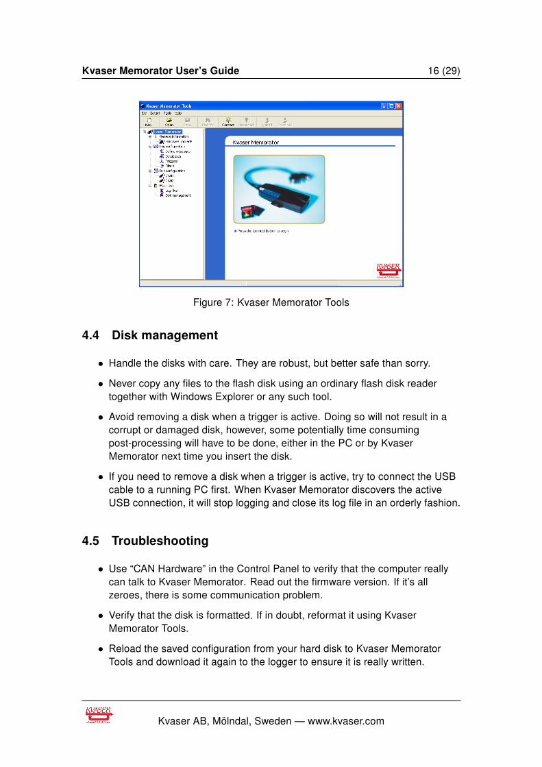
4.3 Kvaser Memorator Tools
To be able to create a configuration and write the created configuration to theKvaser Memorator, first put the Kvaser Memorator in configuration mode, that is,insert a disk and connect the USB cable. Start Kvaser Memorator Tools and pressthe Connect button in the Target menu. If the LEDs on Kvaser Memorator areflashing in a “running light” pattern, the device is in configuration mode.
Kvaser Memorator Tools make it possible to create different configurations for theKvaser Memorator. The main window has got four sections – one for informationabout the device, one for the configuration of the CAN channels, one forconfiguring the trigger conditions and one for disk management and information,and for reading the log files.
For further information about Kvaser Memorator Tools please refer to theapplication’s online help.
Kvaser AB, Mölndal, Sweden — www.kvaser.com
Kvaser Memorator User’s Guide 16 (29)
Figure 7: Kvaser Memorator Tools
4.4 Disk management
• Handle the disks with care. They are robust, but better safe than sorry.
• Never copy any files to the flash disk using an ordinary flash disk readertogether with Windows Explorer or any such tool.
• Avoid removing a disk when a trigger is active. Doing so will not result in acorrupt or damaged disk, however, some potentially time consumingpost-processing will have to be done, either in the PC or by KvaserMemorator next time you insert the disk.
• If you need to remove a disk when a trigger is active, try to connect the USBcable to a running PC first. When Kvaser Memorator discovers the activeUSB connection, it will stop logging and close its log file in an orderly fashion.
4.5 Troubleshooting
• Use “CAN Hardware” in the Control Panel to verify that the computer reallycan talk to Kvaser Memorator. Read out the firmware version. If it’s allzeroes, there is some communication problem.
• Verify that the disk is formatted. If in doubt, reformat it using KvaserMemorator Tools.
• Reload the saved configuration from your hard disk to Kvaser MemoratorTools and download it again to the logger to ensure it is really written.
Kvaser AB, Mölndal, Sweden — www.kvaser.com
Kvaser Memorator User’s Guide 17 (29)
• If configuration fails, verify that Kvaser Memorator is in CONFIG mode whenyou run the Kvaser Memorator Tools. You can see this by looking at theLEDs – they should flash in a “running light” fashion and the KvaserMemorator icon in the main tree view in Kvaser Memorator Tools should notbe covered with a red ring.
• If the LEDs are flashing or glowing, compare the pattern with the table inSection 3.5, LED indicators, on Page 10.
• If the LEDs are not flashing or glowing at all, check the power supply.
Kvaser AB, Mölndal, Sweden — www.kvaser.com
Kvaser Memorator User’s Guide 18 (29)
5 Appendices
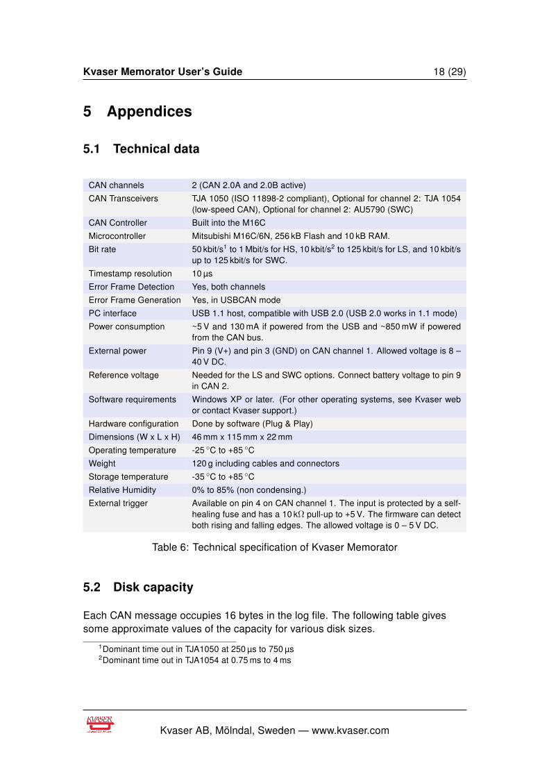
5.1 Technical data
CAN channels 2 (CAN 2.0A and 2.0B active)
CAN Transceivers TJA 1050 (ISO 11898-2 compliant), Optional for channel 2: TJA 1054(low-speed CAN), Optional for channel 2: AU5790 (SWC)
CAN Controller Built into the M16C
Microcontroller Mitsubishi M16C/6N, 256 kB Flash and 10 kB RAM.
Bit rate 50 kbit/s1 to 1 Mbit/s for HS, 10 kbit/s2 to 125 kbit/s for LS, and 10 kbit/sup to 125 kbit/s for SWC.
Timestamp resolution 10 µs
Error Frame Detection Yes, both channels
Error Frame Generation Yes, in USBCAN mode
PC interface USB 1.1 host, compatible with USB 2.0 (USB 2.0 works in 1.1 mode)
Power consumption ~5 V and 130 mA if powered from the USB and ~850 mW if poweredfrom the CAN bus.
External power Pin 9 (V+) and pin 3 (GND) on CAN channel 1. Allowed voltage is 8 –40 V DC.
Reference voltage Needed for the LS and SWC options. Connect battery voltage to pin 9in CAN 2.
Software requirements Windows XP or later. (For other operating systems, see Kvaser webor contact Kvaser support.)
Hardware configuration Done by software (Plug & Play)
Dimensions (W x L x H) 46 mm x 115 mm x 22 mm
Operating temperature -25 C to +85 C
Weight 120 g including cables and connectors
Storage temperature -35 C to +85 C
Relative Humidity 0% to 85% (non condensing.)
External trigger Available on pin 4 on CAN channel 1. The input is protected by a self-healing fuse and has a 10 kΩ pull-up to +5 V. The firmware can detectboth rising and falling edges. The allowed voltage is 0 – 5 V DC.
Table 6: Technical specification of Kvaser Memorator
5.2 Disk capacity
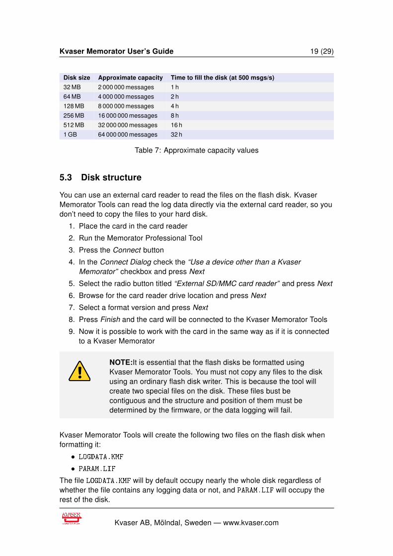
Each CAN message occupies 16 bytes in the log file. The following table givessome approximate values of the capacity for various disk sizes.
1Dominant time out in TJA1050 at 250 µs to 750 µs2Dominant time out in TJA1054 at 0.75 ms to 4 ms
Kvaser AB, Mölndal, Sweden — www.kvaser.com
Kvaser Memorator User’s Guide 19 (29)
Disk size Approximate capacity Time to fill the disk (at 500 msgs/s)
32 MB 2 000 000 messages 1 h
64 MB 4 000 000 messages 2 h
128 MB 8 000 000 messages 4 h
256 MB 16 000 000 messages 8 h
512 MB 32 000 000 messages 16 h
1 GB 64 000 000 messages 32 h
Table 7: Approximate capacity values
5.3 Disk structure
You can use an external card reader to read the files on the flash disk. KvaserMemorator Tools can read the log data directly via the external card reader, so youdon’t need to copy the files to your hard disk.
1. Place the card in the card reader
2. Run the Memorator Professional Tool
3. Press the Connect button
4. In the Connect Dialog check the “Use a device other than a KvaserMemorator” checkbox and press Next
5. Select the radio button titled “External SD/MMC card reader” and press Next
6. Browse for the card reader drive location and press Next
7. Select a format version and press Next
8. Press Finish and the card will be connected to the Kvaser Memorator Tools
9. Now it is possible to work with the card in the same way as if it is connectedto a Kvaser Memorator
NOTE:It is essential that the flash disks be formatted usingKvaser Memorator Tools. You must not copy any files to the diskusing an ordinary flash disk writer. This is because the tool willcreate two special files on the disk. These files bust becontiguous and the structure and position of them must bedetermined by the firmware, or the data logging will fail.
Kvaser Memorator Tools will create the following two files on the flash disk whenformatting it:
• LOGDATA.KMF
• PARAM.LIF
The file LOGDATA.KMF will by default occupy nearly the whole disk regardless ofwhether the file contains any logging data or not, and PARAM.LIF will occupy therest of the disk.
Kvaser AB, Mölndal, Sweden — www.kvaser.com
Kvaser Memorator User’s Guide 20 (29)
5.4 CAN Channel Transceivers
The standard Kvaser Memorator has two high-speed (HS) channels with TJA 1050drivers. As an option the second CAN channel (only the second channel, i.e.channel 1 is always HS) can be delivered with a low-speed (LS) or single-wire CAN(SWC) driver.
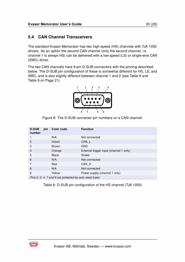
The two CAN channels have 9-pin D-SUB connectors with the pinning describedbelow. The D-SUB pin configuration of these is somewhat different for HS, LS, andSWC, and is also slightly different between channel 1 and 2 (see Table 8 andTable 9 on Page 21).
Figure 8: The D-SUB connector pin numbers on a CAN channel.
D-SUB pinnumber
Color code Function
1 N/A Not connected
2 Green CAN_L
3 Brown GND
4 Orange External trigger input (channel 1 only)
5 Black Shield
6 N/A Not connected
7 Red CAN_H
8 N/A Not connected
9 Yellow Power supply (channel 1 only)
Pins 2, 3, 4, 7 and 9 are protected by auto reset fuses
Table 8: D-SUB pin configuration of the HS channel (TJA 1050)
Kvaser AB, Mölndal, Sweden — www.kvaser.com
Kvaser Memorator User’s Guide 21 (29)
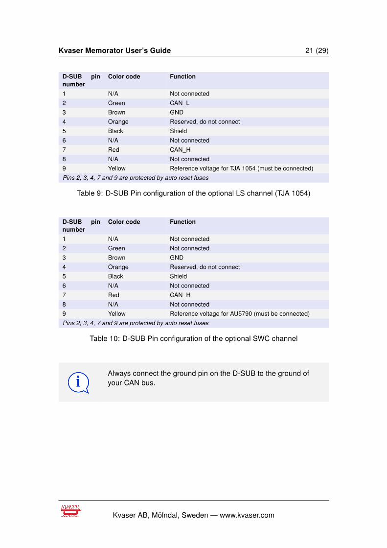
D-SUB pinnumber
Color code Function
1 N/A Not connected
2 Green CAN_L
3 Brown GND
4 Orange Reserved, do not connect
5 Black Shield
6 N/A Not connected
7 Red CAN_H
8 N/A Not connected
9 Yellow Reference voltage for TJA 1054 (must be connected)
Pins 2, 3, 4, 7 and 9 are protected by auto reset fuses
Table 9: D-SUB Pin configuration of the optional LS channel (TJA 1054)
D-SUB pinnumber
Color code Function
1 N/A Not connected
2 Green Not connected
3 Brown GND
4 Orange Reserved, do not connect
5 Black Shield
6 N/A Not connected
7 Red CAN_H
8 N/A Not connected
9 Yellow Reference voltage for AU5790 (must be connected)
Pins 2, 3, 4, 7 and 9 are protected by auto reset fuses
Table 10: D-SUB Pin configuration of the optional SWC channel
Always connect the ground pin on the D-SUB to the ground ofyour CAN bus.
Kvaser AB, Mölndal, Sweden — www.kvaser.com
Kvaser Memorator User’s Guide 22 (29)
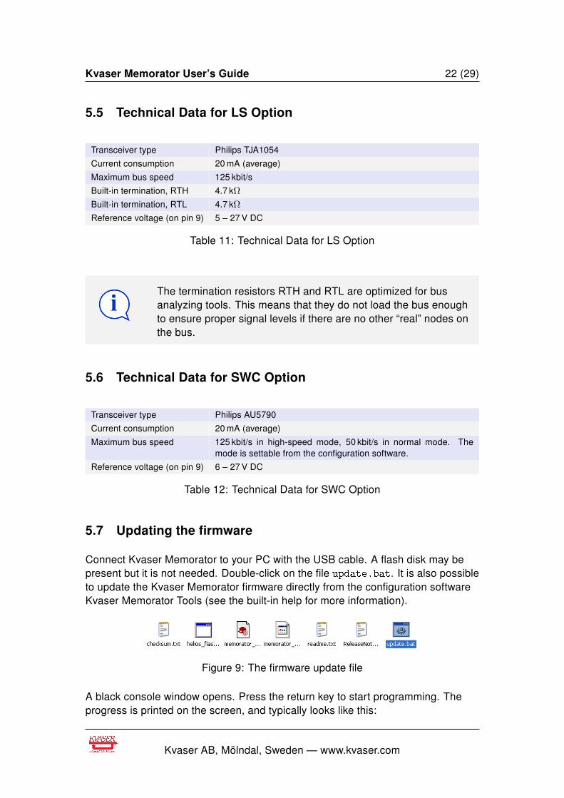
5.5 Technical Data for LS Option
Transceiver type Philips TJA1054
Current consumption 20 mA (average)
Maximum bus speed 125 kbit/s
Built-in termination, RTH 4.7 kΩ
Built-in termination, RTL 4.7 kΩ
Reference voltage (on pin 9) 5 – 27 V DC
Table 11: Technical Data for LS Option
The termination resistors RTH and RTL are optimized for busanalyzing tools. This means that they do not load the bus enoughto ensure proper signal levels if there are no other “real” nodes onthe bus.
5.6 Technical Data for SWC Option
Transceiver type Philips AU5790
Current consumption 20 mA (average)
Maximum bus speed 125 kbit/s in high-speed mode, 50 kbit/s in normal mode. Themode is settable from the configuration software.
Reference voltage (on pin 9) 6 – 27 V DC
Table 12: Technical Data for SWC Option
5.7 Updating the firmware
Connect Kvaser Memorator to your PC with the USB cable. A flash disk may bepresent but it is not needed. Double-click on the file update.bat. It is also possibleto update the Kvaser Memorator firmware directly from the configuration softwareKvaser Memorator Tools (see the built-in help for more information).
Figure 9: The firmware update file
A black console window opens. Press the return key to start programming. Theprogress is printed on the screen, and typically looks like this:
Kvaser AB, Mölndal, Sweden — www.kvaser.com

Kvaser Memorator User’s Guide 23 (29)
Firmware programmer for USBcan Rev B, USBcan II, Kvaser Memorator,
PCIcan II, etc.
Copyright 2002 KVASER AB, Sweden -- http://www.kvaser.com
Using firmware file 'memorator_p030a_nodebug.img'
Loading image file 'memorator_p030a_nodebug.img'...
Binary data: size=37198, start_addr=0xc0018, load_addr=0xc0000
Firmware data:
Build string: V1.5.0 (Dec 07 2002 12:41:37)
HAL: DIANA_C
Variant: MEMORATOR
Image type: FIRMWARE
Erasing...
Download started: #####################################
Download complete.
Starting compare: #####################################
Compare finished.
No error messages should appear. If you see error messages, try to disconnectand reconnect the device, and then perform the operation again.
To verify that the firmware is updated,
• (CANlib 3.7 or older) double-click on “CAN Hardware” in the Control Panel.Then select “USBcan II” (Kvaser Memorator is listed as an USBcan II), andpress the “Hardware Info” button. You can then see the firmware version inthe popup window.
• (CANlib 3.8 or later) double-click on “Kvaser Hardware” in the Control Panel.Select “Kvaser Memorator” in the tree view to the left, and click on eitherchannel. The firmware revision information appears in the right half of thewindow.
5.8 Overrun
Under heavy load, high bit rates and long bursts of messages, Kvaser Memoratorcan lose messages. If this happens Kvaser Memorator Tools will display amessage about this when the file is extracted. Some of the file formats, thatsupport such a feature, will also indicate where the overrun occurred. (See helpsection in Kvaser Memorator Tools for details about file formats.)
To avoid losing important messages during logging, filters can be used. This willdecrease the load on Kvaser Memorator and ensure that important information isnot lost.
Kvaser AB, Mölndal, Sweden — www.kvaser.com
Kvaser Memorator User’s Guide 24 (29)
6 Frequently Asked Questions
Q: How many messages per second can Kvaser Memorator store on thedisk?
A: It depends on the flash disk type. Fast disks can typically accommodate 2000 –4000 messages per second.
Q: How many hours will a 256 MB disk last?
A: It depends on the CAN bus load. See Section 5.2, Disk capacity, on Page 18 toget a feeling for the numbers involved.
Q: Can I use 1 GB disks?
A: Yes. See our web site for a list of recommended disk types.
Q: Can I use any SD/MMC disk?
A: In principle, yes. However, there are many disks that do not conform to thestandard. We recommend the disk brand(s) and type(s) we list on our web site.
Q: Can I use an external SD/MMC card reader to read the logged data?
A: Yes, Kvaser Memorator Tools can read data from external disk readers, as wellas directly from a connected Kvaser Memorator.
Q: I have logged a lot of data on my Kvaser Memorator and now I’m trying toopen the list of files inside Kvaser Memorator Tools, but it seems to hang.What’s up?
A: If the Kvaser Memorator was interrupted while it was writing to the disk, it mighttake a long time to extract the list of files. Please be patient – eventually the list offiles will appear. See Section 4.2, How to disconnect Kvaser Memorator from aCAN system, on Page 14 for advice on how to avoid this situation.
Kvaser AB, Mölndal, Sweden — www.kvaser.com

Kvaser Memorator User’s Guide 25 (29)
7 Disposal and Recycling Information
When this product reaches its end of life, please dispose of itaccording to your local environmental laws and guidelines.
Dispose of batteries according to your local environmental lawsand guidelines.
For information about Kvaser’s recycling programs, visit:http://www.kvaser.com/en/kvaser/recycling-policy.html
Kvaser AB, Mölndal, Sweden — www.kvaser.com

Kvaser Memorator User’s Guide 26 (29)
8 Legal acknowledgements
8.1 Usage warning
WARNING FOR ALL USERSWARNING! - YOUR USE OF THIS DEVICE MUST BE DONE WITH CAUTION AND A FULLUNDERSTANDING OF THE RISKS!THIS WARNING IS PRESENTED TO INFORM YOU THAT THE OPERATION OF THIS DEVICEMAY BE DANGEROUS. YOUR ACTIONS CAN INFLUENCE THE BEHAVIOR OF A CAN-BASEDDISTRIBUTED EMBEDDED SYSTEM, AND DEPENDING ON THE APPLICATION, THECONSEQUENCES OF YOUR IMPROPER ACTIONS COULD CAUSE SERIOUS OPERATIONALMALFUNCTION, LOSS OF INFORMATION, DAMAGE TO EQUIPMENT, AND PHYSICALINJURY TO YOURSELF AND OTHERS. A POTENTIALLY HAZARDOUS OPERATINGCONDITION IS PRESENT WHEN THE FOLLOWING TWO CONDITIONS ARECONCURRENTLY TRUE: THE PRODUCT IS PHYSICALLY INTERCONNECTED TO A REALDISTRIBUTED EMBEDDED SYSTEM; AND THE FUNCTIONS AND OPERATIONS OF THEREAL DISTRIBUTED EMBEDDED SYSTEM ARE CONTROLLABLE OR INFLUENCED BY THEUSE OF THE CAN NETWORK. A POTENTIALLY HAZARDOUS OPERATING CONDITION MAYRESULT FROM THE ACTIVITY OR NON-ACTIVITY OF SOME DISTRIBUTED EMBEDDEDSYSTEM FUNCTIONS AND OPERATIONS, WHICH MAY RESULT IN SERIOUS PHYSICALHARM OR DEATH OR CAUSE DAMAGE TO EQUIPMENT, DEVICES, OR THE SURROUNDINGENVIRONMENT.WITH THIS DEVICE, YOU MAY POTENTIALLY:
• CAUSE A CHANGE IN THE OPERATION OF THE SYSTEM, MODULE, DEVICE,CIRCUIT, OR OUTPUT.
• TURN ON OR ACTIVATE A MODULE, DEVICE, CIRCUIT, OUTPUT, OR FUNCTION.• TURN OFF OR DEACTIVATE A MODULE, DEVICE, CIRCUIT, OUTPUT, OR
FUNCTION.• INHIBIT, TURN OFF, OR DEACTIVATE NORMAL OPERATION.• MODIFY THE BEHAVIOR OF A DISTRIBUTED PRODUCT.• ACTIVATE AN UNINTENDED OPERATION.• PLACE THE SYSTEM, MODULE, DEVICE, CIRCUIT, OR OUTPUT INTO AN
UNINTENDED MODE.ONLY THOSE PERSONS WHO:(A) ARE PROPERLY TRAINED AND QUALIFIED WITH RESPECT TO THE USE OF THEDEVICE,(B) UNDERSTAND THE WARNINGS ABOVE, AND(C) UNDERSTAND HOW THIS DEVICE INTERACTS WITH AND IMPACTS THE FUNCTIONAND SAFETY OF OTHER PRODUCTS IN A DISTRIBUTED SYSTEM AND THE APPLICATIONFOR WHICH THIS DEVICE WILL BE APPLIED, MAY USE THE DEVICE.PLEASE NOTE THAT YOU CAN INTEGRATE THIS PRODUCT AS A SUBSYSTEM INTOHIGHER-LEVEL SYSTEMS. IN CASE YOU DO SO, KVASER AB HEREBY DECLARES THATKVASER AB’S WARRANTY SHALL BE LIMITED TO THE CORRECTION OF DEFECTS, ANDKVASER AB HEREBY EXPRESSLY DISCLAIMS ANY LIABILITY OVER AND ABOVE THEREFUNDING OF THE PRICE PAID FOR THIS DEVICE, SINCE KVASER AB DOES NOT HAVEANY INFLUENCE ON THE IMPLEMENTATIONS OF THE HIGHER-LEVER SYSTEM, WHICHMAY BE DEFECTIVE.
THIS PRODUCT CONTAINS A RECHARGEABLE LI-POL BATTERY THAT
MUST BE DISPOSED OF PROPERLY. IT MAY EXPLODE IF DAMAGED OR
DISPOSED OF IN FIRE. DO NOT SHORT CIRCUIT.
Kvaser AB, Mölndal, Sweden — www.kvaser.com
Kvaser Memorator User’s Guide 27 (29)
8.2 EC Regulatory Compliance
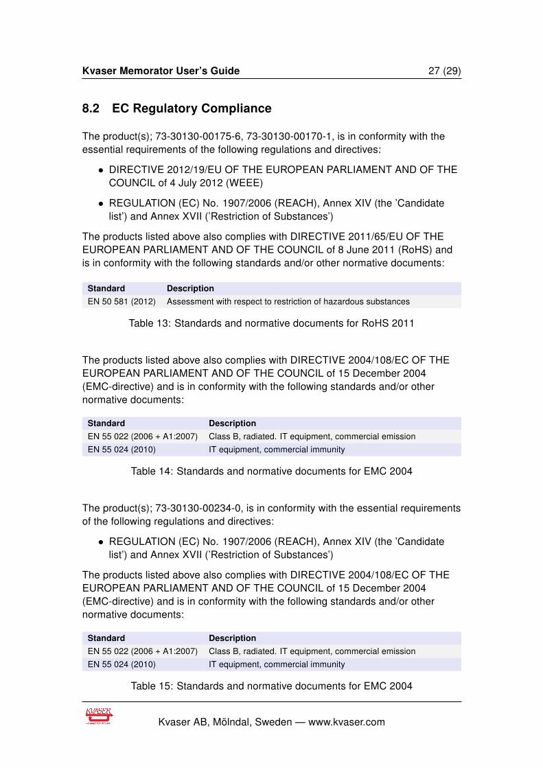
The product(s); 73-30130-00175-6, 73-30130-00170-1, is in conformity with theessential requirements of the following regulations and directives:
• DIRECTIVE 2012/19/EU OF THE EUROPEAN PARLIAMENT AND OF THECOUNCIL of 4 July 2012 (WEEE)
• REGULATION (EC) No. 1907/2006 (REACH), Annex XIV (the ’Candidatelist’) and Annex XVII (’Restriction of Substances’)
The products listed above also complies with DIRECTIVE 2011/65/EU OF THEEUROPEAN PARLIAMENT AND OF THE COUNCIL of 8 June 2011 (RoHS) andis in conformity with the following standards and/or other normative documents:
Standard Description
EN 50 581 (2012) Assessment with respect to restriction of hazardous substances
Table 13: Standards and normative documents for RoHS 2011
The products listed above also complies with DIRECTIVE 2004/108/EC OF THEEUROPEAN PARLIAMENT AND OF THE COUNCIL of 15 December 2004(EMC-directive) and is in conformity with the following standards and/or othernormative documents:
Standard Description
EN 55 022 (2006 + A1:2007) Class B, radiated. IT equipment, commercial emission
EN 55 024 (2010) IT equipment, commercial immunity
Table 14: Standards and normative documents for EMC 2004
The product(s); 73-30130-00234-0, is in conformity with the essential requirementsof the following regulations and directives:
• REGULATION (EC) No. 1907/2006 (REACH), Annex XIV (the ’Candidatelist’) and Annex XVII (’Restriction of Substances’)
The products listed above also complies with DIRECTIVE 2004/108/EC OF THEEUROPEAN PARLIAMENT AND OF THE COUNCIL of 15 December 2004(EMC-directive) and is in conformity with the following standards and/or othernormative documents:
Standard Description
EN 55 022 (2006 + A1:2007) Class B, radiated. IT equipment, commercial emission
EN 55 024 (2010) IT equipment, commercial immunity
Table 15: Standards and normative documents for EMC 2004
Kvaser AB, Mölndal, Sweden — www.kvaser.com
Kvaser Memorator User’s Guide 28 (29)
NOTE: This equipment has been tested and found to comply with the limits for aClass A digital device, pursuant to Part 15 of the FCC Rules. These limits aredesigned to provide reasonable protection against harmful interference when theequipment is operated in a commercial environment. This equipment generates,uses, and can radiate radio frequency energy and, if not installed and used inaccordance with the instruction manual, may cause harmful interference to radiocommunications. Operation of this equipment in a residential area is likely to causeharmful interference in which case the user will be required to correct theinterference at his/her own expense.
8.3 About this manual
This document is Copyright c© 2001-2014 Kvaser AB. This document may not bereproduced without our written permission. Infringement will render the user liableto prosecution.
We believe that the information contained herein was accurate in all respects at thetime of printing. Kvaser AB cannot, however, assume any responsibility for errorsor omissions in this text. Please also note that the information in this document issubject to change without notice and should not be construed as a commitment onthe part of Kvaser AB.
8.4 Patents, copyrights and trademarks
All trademarks are the property of their respective owner. Windows is a registeredtrademark of Microsoft Corporation in the United States and other countries.
Adobe, the Adobe logo, and Reader are either registered trademarks or trademarksof Adobe Systems Incorporated in the United States and/or other countries.
DeviceNet is a Trademark of Open DeviceNet Vendor Association, Inc.
NMEA 2000 is the registered trademark of the National Marine ElectronicsAssociation, Inc.
The products described in this document are protected by U.S. patent 5,696,911.
Kvaser AB, Mölndal, Sweden — www.kvaser.com
Kvaser Memorator User’s Guide 29 (29)
9 Document revision history
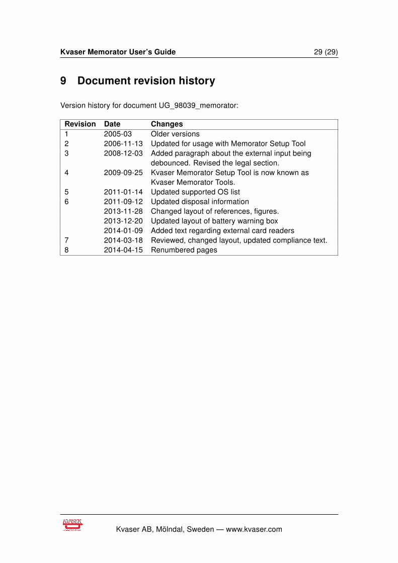
Version history for document UG_98039_memorator:
Revision Date Changes1 2005-03 Older versions2 2006-11-13 Updated for usage with Memorator Setup Tool3 2008-12-03 Added paragraph about the external input being
debounced. Revised the legal section.4 2009-09-25 Kvaser Memorator Setup Tool is now known as
Kvaser Memorator Tools.5 2011-01-14 Updated supported OS list6 2011-09-12 Updated disposal information
2013-11-28 Changed layout of references, figures.2013-12-20 Updated layout of battery warning box2014-01-09 Added text regarding external card readers
7 2014-03-18 Reviewed, changed layout, updated compliance text.8 2014-04-15 Renumbered pages
Kvaser AB, Mölndal, Sweden — www.kvaser.com