kona community hospital · d. whfd and/or project manager furnished/contractor installed products....
TRANSCRIPT

KONA COMMUNITY HOSPITAL
Chapel & Offices
Kealakekua, Island of Hawaii, Hawaii
HAWAII HEALTH SYSTEMS
Kona Community Hospital
79-1019 Haukapila Street
Kealakekua, HI 96750
SPECIFICATIONS
CONSTRUCTION SUBMITTAL
December 2019

Kona Community Hospital 01100-1 Chapel & Offices TABLE OF CONTENTS
KONA COMMUNITY HOSPITAL
Chapel & Offices
Kealakekua, Island of Hawaii, Hawaii
TABLE OF CONTENTS
DIVISION 1 - GENERAL REQUIREMENTS Section 01100 Summary of Work ............................................................... 1 - 4 Section 01120 Alteration Project Procedures ............................................. 1 - 3 Section 01260 Contract Considerations ..................................................... 1 - 7 Section 01290 Payment Procedures .......................................................... 1 - 6 Section 01310 Project Management and Coordination ............................... 1 - 11 Section 01330 Submittal Procedures ......................................................... 1 - 4 Section 01400 Quality Requirements ......................................................... 1 - 3 Section 01500 Temporary Facilities & Controls (Attached: Exhibit A) ......... 1 - 7 Section 01600 Project Requirements ......................................................... 1 - 7 Section 01730 Execution ............................................................................ 1 - 2 Section 01732 Cutting and Patching .......................................................... 1 - 3 Section 01770 Closeout Procedures .......................................................... 1 - 6 Section 01783 Project Record Documents ................................................. 1 - 4 DIVISION 2 – SITE WORK Section 02221 Minor Demolition for Remodeling ........................................ 1 - 2 DIVISION 6 – WOOD AND PLASTICS Section 06070 Wood Treatment ................................................................. 1 – 5 Section 06200 Finish Carpentry ................................................................. 1 – 7 Section 06622 Solid Surface Countertops .................................................. 1 - 4 DIVISION 7 - THERMAL AND MOISTURE PROTECTION Section 07840 Firestopping ........................................................................ 1 – 5 Section 07920 Sealants ............................................................................. 1 – 8 DIVISION 8 – DOORS AND WINDOWS Section 08110 Steel Door Frames ............................................................ 1 – 5 Section 08210 Wood Doors ...................................................................... 1 – 5 Section 08710 Finish Hardware ................................................................ 1 – 4 DIVISION 9 - FINISHES Section 09250 Gypsum Wallboard ............................................................. 1 - 6 Section 09510 Acoustical Ceiling ............................................................... 1 – 3 Section 09901 Painting .............................................................................. 1 - 13

Kona Community Hospital 01100-2 Chapel & Offices TABLE OF CONTENTS
DIVISION 10 - SIGNAGE Section 10440 Signage .............................................................................. 1 - 4 DIVISION 15 - MECHANICAL Section 15000 General Mechanical Requirements ..................................... 1 - 16 Section 15250 Insulation of Mechanical Systems ....................................... 1 - 5 Section 15300 Wet Pipe Sprinkler System ................................................. 1 – 8 Section 15450 Plumbing Fixtures and Trim ............................................... 1 – 2 Section 15500 Automatic Fire Sprinkler System ......................................... 1 - 9 Section 15700 Hydronic Piping, Equipment, and Accessories .................... 1 - 21 Section 15800 Air Conditioning and Ventilation .......................................... 1 - 33 Section 15901 Testing, Adjusting, and Balancing (TAB) ............................. 1 - 7 Section 15950 Networked Building Controls .............................................. 1 - 30 DIVISION 16 – ELECTRICAL Section 16010 Basic Electrical Requirements ............................................ 1 - 5 Section 16047 Electrical Demolition ........................................................... 1 - 3 Section 16060 Grounding & Bonding ......................................................... 1 - 2 Section 16073 Hangers & Supports For Electrical Systems ....................... 1 - 4 Section 16075 Electrical Identification ........................................................ 1 - 4 Section 16120 Conductors & Cables .......................................................... 1 - 3 Section 16130 Raceways & Boxes ............................................................. 1 - 5 Section 16410 Enclosed Switches & Circuit Breaker .................................. 1 - 4 Section 16491 Fuses ................................................................................. 1 - 3 Section 16511 Interior Lighting ................................................................... 1 - 3 Section 16700 Communications ................................................................. 1 - 7 Section 16721 Fire Alarm System .............................................................. 1 - 9

Kona Community Hospital 01100-1 Chapel & Offices SUMMARY OF WORK
DIVISION 1 - GENERAL REQUIREMENTS
SECTION 01100 - SUMMARY OF WORK
PART 1 - General
1.01 SECTION INCLUDES
A. Contract description.
B. Contract use of premises.
C. WEST HAWAII FACILITIES DIRECTOR (WHFD) AND/OR PROJECT MANAGER furnished/WHFD AND/OR PROJECT MANAGER installed products.
D. WHFD AND/OR PROJECT MANAGER furnished/contractor installed products.
E. Hospital occupancy.
1.02 CONTRACT DESCRIPTION
A. HVAC replacement for the existing Chapel and new Offices, at the Kona Community Hospital.
B. The Work of the contract generally consists of the following:
1. Selective demolition within interior of existing hospital
2. Selective demolition and removal of non-structural and structural elements of existing hospital.
3. Renovation of the existing Chapel & Offices HVAC system, including:
a. Affected acoustic ceiling and adjacent interior finishes
b. Sawcutting & patching for existing and new duct openings in concrete
walls.
c. Alteration of associated electrical, lighting & fire sprinkler systems. 1.03 CONTRACTOR USE OF PREMISES
A. Limit the use of premises to allow for continued Hospital occupancy.
B. Emergency Building Exits During Construction: Must remain open and unblocked at all times. Maintain access for staff, patients, and public. Egress must be maintained and way finding signage during construction.
C. Construction Operations: Limited to areas noted on Drawings.
D. Staging and Parking
Kona Community Hospital 01100-2 Chapel & Offices SUMMARY OF WORK
1. Staging area and limited contractor employee parking will be made available on site. Contractor and vendor parking is designated. Any new parking arrangements require prior approval by the WHFD AND/OR PROJECT MANAGER.
E. Time Restrictions for Performing Work: 1. General 6:00 am to 2:30 pm. Coordinate w/ WHFD AND/OR PROJECT
MANAGER, work necessary outside these normal operating hours. Submit written notice a minimum three days in advance.
F. Cooperate with Hospital to minimize conflict and to facilitate Hospital’s operations. Coordinate operations with WHFD AND/OR PROJECT MANAGER.
G. Access to adjacent floors must be approved in advance by the WHFD AND/OR PROJECT MANAGER. Submit written notice not less than seven days in advance of intended work on adjacent floors.
H. Do not close or obstruct roadways without first consulting with the WHFD
AND/OR PROJECT MANAGER. Conduct operations with minimum interference to public or private roadways.
I. Maintain vital services (as defined by the WHFD AND/OR PROJECT MANAGER)
with the minimum of interruption. Outages and interruptions must be approved in advance by the WHFD AND/OR PROJECT MANAGER. Submit written notices of outages and interruptions not less than seven days in advance.
J. Contractor’s personnel:
1. It is preferred that contractors park off site and carpool to hospital.
2. Contractor’s personnel may use the hospital cafeteria.
3. Smoking is not permitted anywhere on KHC property. Consumption of food
and beverages will not be permitted on the premises except in designated areas.
4. Playing of radios will not be permitted.
5. Shall be properly attired for work. (No tank tops, cut-off jeans, slippers, etc.)
6. Shall conduct themselves with decorum and courtesy toward staff, patients,
and public.
7. Shall not use loud and offensive language.
8. Shall read and sign the Contractor’s Guidelines Handbook.
K. Construction Zone Accessibility Requirements
1. General: Hawaii Revised Statutes (HRS) 103-05 requires this project to conform to the requirements of the Americans with Disabilities Act Accessibility Guidelines (ADAAG).

Kona Community Hospital 01100-3 Chapel & Offices SUMMARY OF WORK
2. Ensure accessible routes to emergency entrances and exits to and from accessible parking public pedestrian routes during the construction period as required by ADAAG 4.1.1(4).
3. Temporary buildings and facilities that are not of permanent construction but
are extensively used or are essential for public use for a period of time shall be accessible. Egress must be maintained and way finding signage during construction.
4. Provide temporary safe pedestrian passageway around a construction site.
a. Areas that are used only as work areas shall be designed and
constructed so that individuals with disabilities can approach, enter, and exit the areas.
b. These guidelines do not require that any areas used only as work areas
be constructed to permit maneuvering within the work area or be constructed or equipped (i.e., with racks or shelves) to be accessible.
c. Follow OSHA guidelines concerning scaffolding and debris and dust
protection. 1.04 WHFD AND/OR PROJECT MANAGER FURNISHED/WHFD AND/OR PROJECT
MANAGER INSTALLED PRODUCTS
A. Items noted “OFOI” (WHFD AND/OR PROJECT MANAGER Furnished/WHFD AND/OR PROJECT MANAGER Installed) will be furnished and installed by the WHFD AND/OR PROJECT MANAGER, including but not limited to:
1. Medical equipment.
B. Hospital’s Responsibilities:
1. Arrange for and deliver Hospital reviewed shop drawings, product, data and samples, to Contractor.
2. Upon delivery, inspect products jointly with Contractor.
C. Contractor’s Responsibilities:
1. Review WHFD AND/OR PROJECT MANAGER’s provided shop drawings, product data, and samples.
2. Provide any necessary utility roughs and backing, and install in accordance
with manufacturer’s instructions. 3. Arrange and pay for product delivery to site.
4. Submit claims for transportation damage and replace damaged, defective or
deficient items.
5. Arrange for manufacturers’ warranties, inspections and service.

Kona Community Hospital 01100-4 Chapel & Offices SUMMARY OF WORK
1.05 HOSPITAL OCCUPANCY
A. The Hospital will remain operational during entire period of construction for the conduct of normal operations.
B. The Contractor is to coordinate the work and details within each phase, to
minimize disruption to WHFD AND/OR PROJECT MANAGER’s operation. Advanced notification of a minimum of one week for disruption due to noise and other construction activity is required as well as posting of signage in advance to advise occupants of such disruption.
C. Provide dust and noise barriers where specified under other portions of the
contract documents. Follow ICRA procedures during construction, i.e., Policy #125-54 as attached. Walk off mats at site entrance shall be changed as needed. HEPA filtration units are to be utilized 24 hours per day throughout the construction process. Complete ISLM check sheet daily.
D. Schedule the Work, and cooperate with Hospital to minimize conflict with work
involving dust and noise and odor. PART 2 - Products (Not Used) PART 3 - Execution (Not Used)
END OF SECTION 01100

Kona Community Hospital 01120-1 Chapel & Offices ALTERATION PROJECT PROCEDURES
SECTION 01120 - ALTERATION PROJECT PROCEDURES PART 1 - Products 1.01 SALVAGED MATERIALS
A. Salvage sufficient quantities of cut or removed material to replace damaged work of existing construction, when materials not readily obtainable on current market.
B. Incorporate salvaged or used material only as indicated or with permission of the Hospital.
1.02 PRODUCTS FOR PATCHING AND EXTENDING WORK
A. New Materials: Match existing products and work for patching and extending work.
B. Type and Quality of Existing Products: Determine by inspection and testing products where necessary, referring to existing Work as a standard.
PART 2 - Execution 2.01 EXAMINATION
A. Verify that demolition is complete, and areas are ready for installation of new
Work.
B. Beginning of restoration Work means acceptance of existing conditions. 2.02 PREPARATION
A. Cut, move or remove items as necessary for access to alterations and renovation Work. Replace and restore at completion.
B. Remove unsuitable material not marked for salvage, such as rotted wood,
corroded metals, and deteriorated masonry and concrete. Replace materials as specific for finished Work.
C. Remove debris and abandoned items from area and from concealed spaces.
D. Prepare surface and remove surface finishes to provide for proper installation of
new work and finishes.
E. Close openings in exterior surfaces to protect existing work and salvage items from weather and extremes of temperature and humidity. Insulate duct work and piping to prevent condensation in exposed areas.
F. Do not demolish, chip, or penetrate existing structural members without the
expressed approval of the Prime Consultant.
G. Perform cutting and removal work to remove minimum necessary, and in a manner to avoid damage to adjacent work and provide proper surfaces to receive installation of repair and new Work.

Kona Community Hospital 01120-2 Chapel & Offices ALTERATION PROJECT PROCEDURES
2.03 INSTALLATION
A. Coordinate work of alterations and renovations to expedite completion and to accommodate Owner occupancy.
B. Project areas and Finishes: Complete in all respects including operational, carpentry, casework, mechanical and electrical work.
C. Remove, cut, and patch Work in a manner to minimize damage and to provide a
means of restoring Products and finishes to original or specified condition as appropriate.
D. Refinish visible existing surfaces to remain in renovated rooms and spaces, to
specified condition for each material, with a neat transition to adjacent finishes.
E. In addition to specified replacement of equipment and fixtures, restore existing plumbing, ventilation, air conditioning, air balancing and electrical systems to full operational condition.
2.04 TRANSITIONS
A. Where new Work abuts or aligns with existing, perform a smooth and even
transition. Patched Work to match existing adjacent Work in texture and appearance.
B. Cut finish surfaces such as masonry, tile, plaster, or metals by methods to terminate surfaces in a straight line at a natural point of division.
C. When finished surfaces are cut so that a smooth transition with new Work is
possible, terminate existing surface along a straight line at a natural line of division. Provide trim appropriate to finished surface subject to approval of Hospital’s Representative.
2.05 ADJUSTMENTS
A. Where removal of partitions or walls result in adjacent spaces becoming one,
rework floors, walls and ceiling to a smooth plane without breaks, steps or bulkheads.
B. Where a change of plane ¼ inch or more occurs, submit recommendation for providing a smooth transition for the WHFD AND/OR PROJECT MANAGER review.
C. Trim existing doors as necessary to clear new floor finish. Refinish trim as
required.
D. At penetrations of fire-rated wall, ceiling or floor construction, completely seal voids with fire rated, fire resistant material, full thickness of the construction element.

Kona Community Hospital 01120-3 Chapel & Offices ALTERATION PROJECT PROCEDURES
2.06 REPAIR OF DAMAGED SURFACES
A. Patch or replace portions of existing surfaces which are damaged, lifted, discolored, or showing other imperfections.
B. Repair substrate prior to patching finish. 2.07 FINISHES
A. Finish surfaces as specified in individual Product Sections.
B. Finish patches to product uniform finish and texture over entire area. When finish cannot be matched, refinish entire surface to nearest intersection with written approval of the WHFD AND/OR PROJECT MANAGER.
2.08 CLEANING
A. In addition to cleaning as specified in this specifications. Wet mop owner-occupied
areas daily utilizing hospital’s EPA approved disinfectant. Remove and replace soiled walk off (sticky) mats daily.
B. Clean spillage, over-spray, and dust in Owner- occupied areas immediately. PART 3 - Execution (Not Used)
END OF SECTION 01120
Kona Community Hospital 01260-1 Chapel & Offices CONTRACT CONSIDERATIONS
SECTION 01260 - CONTRACT CONSIDERATIONS PART 1 - General 1.01 SECTION INCLUDES
A. Schedule of values.
B. Application for payment.
C. Change procedures.
1.02 RELATED SECTIONS
A. Section 01100- SUMMARY OF WORK: for allowances.
1.03 SCHEDULE OF VALUES
A. Submit a printed schedule of AIA Form G703- Application and Certificate for Payment Continuation Sheet. Contractor’s standard form or electronic media printout will be acceptable.
B. Submit Schedule of Values in duplicate within 15 days after date of Owner
Contractor Agreement.
C. Format: Utilize the Table of Contents of this Project Manual. Identify each line item with number and title of the major specification Section. Identify site mobilization and bonds and insurance.
D. Include in each line item, the amount of Allowances specified in this section. For
unit cost Allowances, identify quantities taken from Contract Documents multiplied by the unit cost to achieve the total for the item.
E. Include within each line item, a direct proportional amount of Contractor’s
overhead and profit.
F. Revise schedule to list approved Change Orders, with each Application For Payment.
1.04 APPLICATIONS FOR PAYMENT
A. Submit each application electronically on AIA Form G702- Application and
Certificate for Payment and AIA G703- Continuation Sheet or Contractor’s own invoice with all appropriate information. Contractor’s electronic media printout will be acceptable.
B. Content and Format: Utilize Schedule of Values for listing items in Application for Payment.
C. Payment Period: Invoice to be submitted to Hospital Technical Representative for
the preceding month’s work by the 5th day of the month that follows. (The State of Hawaii does its best to pay within 30 days).
Kona Community Hospital 01260-2 Chapel & Offices CONTRACT CONSIDERATIONS
D. Waiver of Liens: Provide unconditional waiver of liens. Use contractor’s form. 1.05 CHANGE PROCEDURES
A. The following documents will be used. Sample forms are attached.
B. Request for Information: Standard Contractor form. A request for information shall
be used by the Contractor to the Prime Consultant to request solutions to problems which are discovered during construction, to request drawings and cost and/or schedule impacts in the Request for Information.
C. Instruction Notice: Attachment 1, standard form.
1. Instruction Notice will be issued by the Prime Consultant for instructions to
the Contractor which do not involve a change in the Contract Sum or construction period.
2. Instruction Notice authorizes the Contractor to proceed at once with the
instruction included therein.
3. Instruction Notice which does affect the Contract Sum or construction period must have written authorization by the Owner’s Project Manager. Such instruction shall have the note “Change Order to Follow” and then be followed with a Quotation Request, cross referenced to the Field Order.
4. Instruction Notice will be distributed as follows:
a. Two copies to Contractor
b. One copy to the Prime Consultant
c. One copy to each appropriate Consultant
d. One copy to WHFD AND/OR PROJECT MANAGER
D. Quotation Requests: Attachment 2, standard Prime Consultant form.
1. Proposed changes to the Contract will be initiated by the Prime Consultant in the form of a Quotation Request.
2. A Quotation Request, indicating the party suggesting the change, will clearly
describe the proposed Contract variation, accompanied by the required drawings, if necessary.
3. Construction work shall not proceed on the strength of a Quotation Request
only.
4. Quotation Requests will be distributed as follows:
a. Two copies to Contractor.
b. One copy to Prime Consultant

Kona Community Hospital 01260-3 Chapel & Offices CONTRACT CONSIDERATIONS
c. One copy to each appropriate Consultant
d. One copy to Owner’s Project Management
5. The Contractor shall respond to the Quotation Request within the time stated on the form.
E. Change Proposal. Standard Contract Form. 1. This form shall be issued by the Contractor for any claims he may have and
in response to a Quotation Request.
2. The Change proposal shall include a description of the work and the requested change to the Contract sum and construction time.
3. All supporting documents, materials and subcontract quotations, time sheets,
labor estimates, etc., shall be itemized and attached to the Change Proposal as necessary for proper checking by the Prime Consultant, Consultants and Owner’s Project Manager.
4. Change proposals, if acceptable, will be signed by the WHFD AND/OR
PROJECT MANAGER and Prime Consultant with one executed copy returned to Contractor. The Contractor shall thus have the authority to proceed with the work and Change Order will follow.
F. Change Order. Attachment 3, standard form.
1. This document is issued to the Contractor as an instruction for him to make a
change to the work of the contract Documents.
2. Change Order documents are prepared by the Prime Consultant and countersigned by the Owner and Contractor.
3. Approved Change orders record the following information:
a. Cross-reference to Change Proposal. b. Summarized description of change in work required.
c. Change in completion date.
d. Change in Contract sum.
e. Identification of party/individual initiating change.
G. Record of Variations: Variations in construction from the plans and specifications
shall be recorded by the Contractor as required in Division 1. These variations shall be brought to the attention of the Prime Consultant and WHFD ANS/OR PROJECT MANAGER by the Contractor.
H. Timeliness of Processing: Instruction notices, Quotation Requests and Change Proposals will be processed and one copy provided the WHFD AND/OR PROJECT MANAGER the same day the document is prepared.
Kona Community Hospital 01260-4 Chapel & Offices CONTRACT CONSIDERATIONS
I. Time and Material Change Order: Submit itemized account and supporting data
after completion of change, within time limits indicated in the Conditions of the Contract Time as provided in the Contract Documents.
J. Maintained detailed records of work done on Time and Material basis. Provide full
information required for evaluation of proposed changes, and to substantiate costs for changes in the Work.
PART 2 - Products (Not Used) PART 3 - Execution (Not Used)
END OF SECTION 01260

Kona Community Hospital 01260-5 Chapel & Offices CONTRACT CONSIDERATIONS
Attachment 1
OPTIONAL
INSTRUCTION NOTICE INSTRUCTION NOTICE NO: DATE: PROJECT NO: PROJECT: Kona Community Hospital Chapel & Offices CONTRACTOR:
Reference: Specifications: Drawings: Other:
YOU ARE HEREBY DIRECTED TO PROMPTLY EXECUTE THIS INSTRUCTION NOTICE WHICH REPRESENTS THE CONTRACT DOCUMENTS OR ORDERS MINOR CHANGES IN THE WORK. If you consider that a change in Contract Sum or Contract Time is required, submit your itemized proposal to the Prime Consultant immediately and before proceeding with the work. If your proposal is found to be satisfactory and in proper order, this Instruction Notice will be superseded by a Change Order.
COPIES TO: WHFD AND/OR PROJECT MANAGER Contractor
Prime Consultant Structural Mechanical Electrical Civil Landscape Others
Attachment 1

Kona Community Hospital 01260-6 Chapel & Offices CONTRACT CONSIDERATIONS
Attachment 2
OPTIONAL
QUOTATION REQUEST QUOTATION REQUEST NO: DATE: PROJECT NO: PROJECT: Kona Community Hospital Chapel & Offices CONTRACTOR:
Submit a fully itemized quotation for the inclusion of the following changes into the contract. This is not a Change Order, a Construction Change Directive, nor an Instruction to proceed with the work herein.
REQUEST ORIGINATED BY: DATE QUOTATION REQUIRED BY: COPIES TO: WHFD AND/OR PROJECT MANAGER Contractor Others

Kona Community Hospital 01260-7 Chapel & Offices CONTRACT CONSIDERATIONS
Attachment 3
CHANGE ORDER
CHANGE ORDER NO: DATE: PROJECT NO: PROJECT: Kona Community Hospital Chapel & Offices CONTRACTOR:
Original Contract Sum was: Net changes by previously authorized Change Orders: $ Contract Sum prior to this Change Order was: $ Contract sum will be (increased) (decreased) (unchanged) by this Change Order $ New Contract Sum including this Change Order will be: $ The Contract Time will be (increased) (decreased) (unchanged) by days The date of Substantial Completion as of the date of this Change Order is:
PRIME CONSULTANT: WHFD AND/OR PROJECT MANAGER: CONTRACTOR: By:________________________ Date:_________________ Approved by:________________ Date:_________________ Accepted by:________________ Date:_________________
Attachment 3

Kona Community Hospital 01290-1 Chapel & Offices PAYMENT PROCEDURES
SECTION 01290 - PAYMENT PROCEDURES PART 1 - Products 1.01 GENERAL CONDITIONS
A. As specified in Division 1.
1.02 RELATED SELECTIONS
A. Section 01260- CONTRACT CONSIDERATIONS for administrative procedures
for handling changes to the Contract.
1.03 DEFINITIONS
A. Schedule of Values: A statement furnished by Contractor allocating portions of the Contract Sum to various portions of the Work and used as the basis for reviewing Contractor’s Application for Payment.
1.04 SCHEDULE OF VALUES
A. Coordination: Coordinate preparation of the schedule of values with preparation of Contractor’s construction schedule.
1. Coordinate line items in the schedule of values with other required
administrative forms and schedules, including the following: a. Application for Payment forms with continuation sheets.
b. Submittal schedule.
c. Items required to be indicated as separate activities in Contractor’s
construction schedule.
2. Submit the schedule of values to the Prime Consultant through the Hospital’s Construction Management Representative at earliest possible date, but no later than seven days before the date scheduled for submittal of initial Applications for Payment.
B. Format and Content: Use Project Manual table of contents as a guide to establish line items for the schedule of values. Provide at least one line item for each Specification Section. 1. Identification: include the following Project identification on the schedule of
values: a. Project name and location.
b. Name of Prime Consultant.
c. Prime Consultant’s project number.
d. Contractor’s name and address.
Kona Community Hospital 01290-2 Chapel & Offices PAYMENT PROCEDURES
e. Date if submittal.
2. Arrange schedule of values consistent with format of AIA Document G703.
3. Arrange the schedule of values in tabular form with separate columns to indicate the following for each items listed:
a. Related Specification Section or Division.
b. Description of the Work
c. Name of subcontractor
d. Name of manufacturer or fabricator.
e. Name of supplier.
f. Change Orders (numbers) that affected value.
g. Dollar value of the following, as percentage of the Contract Sum to
nearest on-hundredth percent, adjusted to total 100 percent.
1) Labor 2) Materials
3) Equipment
4. Provide a breakdown of the Contract Sum in enough detail to facilitate
continued evaluation of Applications for Payment and progress reports. Coordinate with Project Manual table of contents. Provide multiple line items for principal subcontract amounts in excess of two percent of the Contract Sum.
a. Include separate line items under Contractor and principal subcontracts
for Project closeout requirements in an amount totaling two percent of the Contract Sum and subcontract amount.
5. Round amounts to nearest whole dollar; total shall equal the Contract Sum.
6. Provide separate line item in the schedule of values for each part of the Work
where Applications for Payment may include materials or equipment purchased or fabricated and stored, but not yet installed.
a. Differentiate between items stored on-site and items stored off-site. If
required, include evidence of insurance.
7. Provide separate line items in the schedule of values for initial cost of materials, for each subsequent stage of completion, and for total installed value of that part of the Work.

Kona Community Hospital 01290-3 Chapel & Offices PAYMENT PROCEDURES
8. Each item in the schedule of values and Application for Payments shall be complete. Include total cost and proportionate share of general overhead and profit for each item.
a. Temporary facilities and other major cost items that are not direct cost of
actual work-in-place may be shown either as separate line items in the schedule of values or distributed as general overhead expense, at Contractor’s option.
9. Schedule Updating: Update and resubmit the schedule of values before the
next Applications for Payment when Change Orders or Construction Change Directives result in a change in the Contract Sum.
1.05 APPLICATIONS FOR PAYMENT
A. Each Application for Payment following the initial Application for Payment shall be consistent with previous applications and payments as approved by the Hospital Construction Project Manager. 1. Initial Application for Payment, Application for Payment at time of Substantial
Completion, and final Application for Payment involve additional requirements.
B. Payment Application Times: Each progress payment shall be submitted monthly.
C. Payment Application Times: Submit Application for Payment to the Prime Consultant by the 5th day of the month. The period covered by each Application for Payment is one month, ending on the last day of the month.
D. Application for Payment Forms: Use AIA G702 and Document AIA G703 or
Contractor’s own form as a form for Application for Payment.
E. Application Preparation: Complete every entry on form. Contract number must be on every application for payment. The Prime Consultant will return incomplete applications, including those without the contract number, without action.
1. Entries shall match data on the schedule of values and Contractor’s
construction schedule. Use updated schedules if revisions were made. 2. Include amounts for work completed following previous Application for
Payment, whether or not payment has been received. Include only amounts for work completed at time of Application for Payment.
3. Include amounts of Change Orders and Construction Change Directives
issued before last day of construction period covered by application.
4. Indicate separate amounts for work being carried out under Owner-requested project acceleration.
F. Stored Materials: Include in Application for Payment amounts applied for materials
or equipment purchased or fabricated and stored, but not yet installed. Differentiate between items stored on-site and items stored off-site.

Kona Community Hospital 01290-4 Chapel & Offices PAYMENT PROCEDURES
1. Provide supporting documentation that verifies amount requested, such as paid invoices. Match amount requested with amounts indicated on documentation; do not include overhead and profit on stored materials.
G. Transmittal: submit signed Application for Payment to Hospital Construction Project Manager (electronically or by hand delivery). Include waivers of lien and similar attachments of required.
H. Waivers of Mechanic’s Lien: With each Application for Payment, submit waivers of mechanic’s lien from entities lawfully entitled to file a mechanic’s lien arising out of the contract and related to the Work covered by the payment.
1. Submit partial waivers on each item for amount requested in previous
application, after deduction for retainage, on each item. 2. When application shows completion of an item, submit conditional final or full
waivers.
3. WHFD AND/OR PROJECT MANAGER reserves the right to designate which entities involved in the Work must submit waivers.
4. Waiver forms: Submit executed waivers of lien on forms acceptable to
Owner.
I. Waiver of Mechanic’s Lien: With each Application for Payment, submit waivers of mechanic’s lien from subcontractors, sub-contractors, and suppliers for construction period covered by the previous application.
1. Submit partial waivers on each item for amount requested in previous
application, after deduction for retainage, on each item. 2. When an application shows completion of an item, submit conditional final or
full waivers.
3. WHFD AND/OR PROJECT MANAGER reserves the right to designate which entities involved in the Work must submit waivers.
4. Submit final Application for Payment with or proceeded by conditional final
waivers from every entity involved with performance of the work covered by the application who is lawfully entitled to a lien.
5. Waiver forms: Submit executed waivers of lien forms, acceptable to Owner.
J. Initial Application for Payment: Administrative actions and submittals that must
precede or coincide with submittal of first Application for Payment include the following:
1. List of subcontractors. 2. Schedule of values.
3. Contractor’s construction schedule (preliminary if not final).

Kona Community Hospital 01290-5 Chapel & Offices PAYMENT PROCEDURES
4. Products list (preliminary if not final).
5. Schedule of unit prices.
6. Submittal schedule (preliminary of not final).
7. List of Contractor’s staff assignments.
8. List of Contractor’s principal’s consultants.
9. Copies of building permits.
10. Copies of authorizations and licenses from authorities having jurisdiction for performance of the Work.
11. Initial progress report.
12. Report of preconstruction conference.
13. Certificates of insurance and insurance policies.
14. Performance and payment bonds.
15. Data needed to acquire Owner’s insurance.
K. Application for Payment at Substantial Completion: After Prime Consultant issues
the Certificate of Substantial Completion, submit an Application for Payment showing 100 percent completion for potion of the Work claimed as substantially complete.
1. Include documentation supporting claim that the Work is substantially
complete and a statement showing an accounting of changes to the Contract sum.
2. This application shall reflect Certificate(s) of Substantial Completion issued
previously for Owner occupancy of designated portions of the Work.
L. Final Payment Application: After completing Project closeout requirements, submit final Application for Payment with releases and supporting documentation not previously submitted and accepted, including, but not limited, to the following:
1. Evidence of completion of Project closeout requirements. 2. Insurance certificates for products and completed operations where required
and proof that taxes, fees, and similar obligations were paid.
3. Updated final statement, accounting for final changes to the Contract Sum.
4. AIA Document G706, “Contractor’s Affidavit of Payment of Debts and Claims”.
5. AIA Document G706A, “Contractor’s Affidavit of Releases of Liens”.

Kona Community Hospital 01290-6 Chapel & Offices PAYMENT PROCEDURES
6. AIA Document G707, “Consent of Surety to Final Payment”.
7. Evidence that claims have been settled.
8. Final liquidated damages settlement statement.
9. Alternate forms may be utilized with approval from the WHFD AND/OR PROJECT MANAGER & Contracts Manager
PART 2 - Products (Not Used) PART 3 - Execution (Not Used)
END OF SECTION 01290
Kona Community Hospital 01310-1 Chapel & Offices PROJECT MANAGEMENT AND COORDINATION
SECTION 01310 - PROJECT MANAGEMENT AND COORDIANTION PART 1 - General 1.01 SECTION INCLUDES
A. General Coordination procedures
B. Coordination drawings.
C. Requests for information (RFI’s)
D. Project Web site.
E. Project Meetings.
1.02 RELATED SECTIONS
A. Section 01770 “CLOSEOUT PROCEDURES” for coordinating closeout of the Contract.
1.03 DEFINITIONS
A. RFI: (Request for Information), the Prime Consultant for seeking information required by or clarifications of the Contract Documents.
1.04 INFORMATION SUBMITTALS
A. Subcontract List: Prepare a written summary (provided herein as Attachment 4) identifying individuals or firms proposed for each portion of the Work, including those who are to furnish products or equipment fabricated to a special design. Included the following information in tabular form: 1. Name, address and telephone number of company performing subcontract or
supplying products.
2. The particular work to be performed by subcontractor.
B. Key personnel Names: Within 7 days of starting construction operations, submit a list of key personnel assignments, including superintendent and other personnel in attendance at Project site. Identify individuals and their duties and responsibilities; list addresses and telephone numbers, including home, office and cellular telephone numbers and e-mail addresses. Provide names, addresses and telephone numbers of individuals assigned as alternates in the absence of individuals assigned to Project.
1. Post copies of list in project meeting room, in temporary field office and by
each temporary telephone. Keep list current at all times.
1.05 GENERAL COORDINATION PROCEDURES
A. Coordination: Coordinate construction operations included in different Sections of the Specifications to ensure efficient and orderly installation of each part of the

Kona Community Hospital 01310-2 Chapel & Offices PROJECT MANAGEMENT AND COORDINATION
Work. Coordinate construction operations, included in different Sections that depend on each other for proper installation, connection, and operation. 1. Schedule construction operations in sequence required to obtain the best
results where installation of one part of the Work depends on installation of other components, before or after its own installation.
2. Coordinate installation of different components to ensure maximum
performance and accessibility for required maintenance, service, and repair.
3. Make adequate provisions to accommodate items scheduled for later installation.
B. Coordination: Each contractor shall coordinate its construction operations with
those of other contractors and entities to ensure efficient and orderly installation of each part of the Work. Each contractor shall coordinate its operations with operations, included in different Sections that depend on each other for proper installation, connection, and operations. 1. Schedule construction operations in sequence required to obtain the best
results where installation of one part of the Work depends on installation of other components, before or after its own installation.
2. Coordinate installation of different components with other contractors to ensure maximum performance and accessibility for required maintenance, service, and repair.
3. Make adequate provisions to accommodate items scheduled for later
installation.
C. Prepare memoranda for distribution to each party involved, outlining special procedures required for coordination. Include such items as required notices, reports and list of attendees at meetings. 1. Prepare similar memoranda for Owner and separate contractors of
coordination of their Work is required.
D. Administrative Procedures: Coordinate scheduling and timing of required administrative procedures with other construction activities and (activities of other contractors) to avoid conflicts and to ensure orderly progress of the Work. Such administrative activities include, but are not limited to, the following: 1. Preparation of Contractor’s construction schedule.
2. Preparation of the schedule of values.
3. Installation and removal of temporary facilities and controls.
4. Delivery and processing of submittals.
5. Progress meetings.
6. Pre-installation of conferences.

Kona Community Hospital 01310-3 Chapel & Offices PROJECT MANAGEMENT AND COORDINATION
7. Project closeout activities.
8. Startup and adjustment of systems.
E. Conservation: Coordinate construction activities to ensure that operations are
carried out with consideration given to conservation of energy, water, and materials. Coordinate use of temporary utilities to minimize waste.
1. Salvage materials and equipment involved in performance of but not actually
incorporated into, the Work. See other Sections for disposition of salvaged materials that are designed as Owner’s property.
1.06 COORDINATION DRAWINGS
A. Coordination Drawings, General: Prepare coordination drawings according to requirements in individual Sections, and additionally where installation is not completely shown on Shop Drawings, where limited space availability necessitates coordination, or if coordination is required to facilitate integration of products and materials fabricated or installed by more than one entity. 1. Content: Project-specific information, drawn accurately to a scale large
enough to indicate and resolve conflicts. Do not base coordination drawings on standard printed data. Include the following information, as applicable: a. Use applicable Drawings as a basis for preparation of coordination
drawings. Prepare sections, elevations, and details as needed to describe relationship of various systems and components.
b. Coordinate the addition of trade-specific information to the coordination drawings by multiple contracts in a sequence that best provides for coordination of the information and resolution of conflicts between installed components before submitting for review.
c. Indicate functional and spatial relationships of components of
architectural, structural, civil, mechanical, and electrical systems.
d. Indicate space requirements for routine maintenance and for anticipated replacement of components during the life of the installation.
e. Show location and size of access doors required for access to concealed
dampers, valves, and other controls.
f. Indicate required installation sequences.
g. Indicate dimensions show in the Drawings. Specifically note dimensions that appear to be in conflict with submitted equipment and minimum clearance requirements. Provide alternate sketches to Prime Consultant indicating proposed resolution of such conflicts. Minor dimensions changes and difficulty installations will not be considered changes to the Contract.
B. Coordinating Drawing Organization: Organize coordination drawings as follows:

Kona Community Hospital 01310-4 Chapel & Offices PROJECT MANAGEMENT AND COORDINATION
1. Floor Plans and Reflected Ceiling Plans: Show architectural and structural
elements and mechanical, plumbing, fire-protection, fire-alarm and electrical work. Show locations of visible ceiling-mounted devices relative to acoustical ceiling grid. Supplement plan drawings with section drawings where required to adequately represent the Work.
2. Plenum Space: indicate subframing for support of ceiling and wall systems,
mechanical and electrical equipment, and related work. Locate components within ceiling plenum to accommodate layout of light fixtures indicated on Drawings. Indicate areas conflict between light fixtures and other components. All work to be seismically anchored utilizing TOLCO system.
3. Mechanical rooms: Provide coordination drawings for mechanical rooms
showing plans and elevations of mechanical, plumbing, fire-protection, fire-alarm, and electrical equipment.
4. Structural Penetrations: Indicate penetrations and openings required for all
disciplines.
5. Slab Edge and Embedded items: Indicate slab edge locations and sizes and locations of embedded items for metal fabrications, sleeves, anchor bolts, bearing plates, angles, door floor closers, slab depressions for floor finishes, curbs and housekeeping pads, and similar items.
6. Mechanical and Plumbing Work: Show the following:
a. Sizes and bottom elevations of ductwork, piping, and conduit runs,
including insulation, bracing, flanges and support systems. All work to be seismically anchored using TOLCO system.
b. Dimensions of major components, such as dampers, valves, diffusers,
access doors, cleanouts and electrical distribution equipment.
c. Fire –rated enclosures around ductwork.
7. Electrical Work: Show the following:
a. Runs of vertical and horizontal conduit 1-1/4 inches (32 mm) in diameter and larger.
b. Light fixture, exit light, emergency battery pack, smoke detector, and
other fire-alarm locations.
c. Panel board, switch board, switchgear, transformer, busway, generator, and motor control center locations.
d. Location of pull boxes and junction boxes, dimensioned from column
center lines.
8. Fire-Protection System: Show the following:

Kona Community Hospital 01310-5 Chapel & Offices PROJECT MANAGEMENT AND COORDINATION
a. Locations of standpipes, main piping, branch lines, pipe drops and sprinkler heads.
9. Review: Prime Consultant will review coordination drawings to confirm that
the Work is being coordinated, but not for the details of the coordination, which are Contractor’s responsibility. If Prime Consultant determines that coordination drawings are not being prepared in sufficient scope or details, or are otherwise deficient, Prime Consultant will so inform Contractor, who shall make changes as direct and resubmit.
10. Coordination Drawing Prints: Prepare coordination drawing prints according to requirements on Section 013300 “Submittal Procedures”.
C. Coordination Digital Data Files: Prepare coordination digital data files according to the following requirements: 1. File Preparation Format: Same digital data software program, version, and
operating system as original Drawings.
2. File Submittal Format: Submit or post coordination drawing files using Portable Data File (PDF) format.
3. Prime Consultant will furnish Contractor one set of digital data files of
Drawings for use in preparing coordinated digital data files.
a. Digital Data Software Program: Drawings are available in AutoCAD 2010. b. Contractor shall execute a data licensing agreement in the form of
Agreement form acceptable to WHFD AND/OR PROJECT MANAGER and Prime Consultant, if required by either party.
1.07 REQUESTS FOR INFORMATION (RFI’S)
A. General: Immediately of discovery of the need for additional information or interpretation of the Contract Documents, Contractor shall prepare and submit an RFI in the form specified to WHFD AND/OR PROJECT MANAGER. 1. All RFIs must be submitted directly by the Contractor of record. Prime
Consultant will return RFI submitted to Prime Consultant by other entities controlled by Contractor with no response.
2. Coordinate and submit RFIs in a prompt manner so as to avoid delays in Contractor’s work or work of subcontractors.
B. Content of the RFI: Include a detailed, legible description of item needing
information or interpretation and the following: 1. Project name.
2. Project number.
3. Date.

Kona Community Hospital 01310-6 Chapel & Offices PROJECT MANAGEMENT AND COORDINATION
4. Name of Contractor.
5. Name of Project Engineer.
6. RFI number, number sequentially.
7. RFI subject.
8. Specification Section number and title and related paragraphs, as appropriate.
9. Drawing number and detail references, as appropriate.
10. Field dimensions and conditions, as appropriate.
11. Contractor’s suggested resolution. If Contractor’s suggested resolution
impacts the Contract Time or the Contract Sum, Contractor shall state impact in the RFI.
12. Contractor’s signature.
13. Attachments: Include sketches, description, measures, photos, Product Data,
Shop Drawings, coordination drawings, and other information necessary to fully describe items needing interpretation.
a. Include dimensions, thickness, structural grid references, and details of
affected materials, assemblies, and attachments on attached sketches.
14. Response turnaround time needed.
C. RFI Forms: Contractor’s form
1. Attachment shall be electronic files preferably in Adobe Acrobat PDF format.
D. Project Prime Consultant’s Action: Project Prime Consultant will review each RFI, determine action required and respond within requested response time, typically 3 working days unless quicker response is needed as to not delay the project. 1. The following Contract-generated RFIs will be returned without action:
a. Requests for approval of submittals.
b. Requests for approval of substitutions.
c. Requests for approval of Contractor’s mean and methods.
d. Requests for coordination information already indicated in the Contract
Documents.
e. Requests for adjustment in the Contract Time or Contract Sum.
f. Requests for interpretation of Prime Consultant’s actions on submittals.

Kona Community Hospital 01310-7 Chapel & Offices PROJECT MANAGEMENT AND COORDINATION
g. Incomplete RFIs or inaccurately prepared RFIs.
2. The Prime Consultant’s action may include a request for additional information, in which case the time for response will date from time of receipt of additional information.
3. The Project Prime Consultant’s action on RFIs that may result in a change to the Contract Time or the Contract sum may be eligible for Contractor to submit Change Proposal according to Section 012600 “Contract Modification Procedures”.
a. If Contractor believes the RFI response warrants change in the Contract
Time or the Contract Sum, notify the WHFD AND/OR PROJECT MANAGER in writing within 3 days of receipt of the RFI response.
E. RFI Log: Prepare, maintain, and submit a tabular log of RFIs organized by the RFI number. Submit log weekly to Prime Consultant. 1. Project name.
2. Name and address of Contractor.
3. Name and address of Project Prime Consultant.
4. RFI numbering including RFIs that were returned without action or withdrawn.
5. RFI description.
6. Date when the RFI was submitted.
7. Date when the Prime Consultant’s response was received.
1.08 PROJECT MEETINGS
A. General: Schedule and conduct meetings and conferences ar Project site unless
otherwise indicated
1. Attendees: Inform participants and others involved, and individuals whose presence is required, of date and time of each meeting. Notify WHFD AND/OR PROJECT MANAGER and Prime Consultant of scheduled meeting dates and times. It is preferred that a standing meeting day/time is planned at the commencement of the project.
2. Agenda: Contractor shall prepare the meeting agenda. Distribute the agenda
to all invited attendees.
3. Sign in Sheet: Furnish and supply a copy of completed sheet to KCH.
4. Minutes: Entity responsible for conducting meeting will record significant discussions and agreements achieved. Distribute the meeting minutes to all meeting attendees within three business days of the meeting.

Kona Community Hospital 01310-8 Chapel & Offices PROJECT MANAGEMENT AND COORDINATION
B. Preconstruction Conference: the WHFD AND/OR PROJECT MANAGER will schedule and conduct a preconstruction conference before starting construction, at a time convenient to the Hospital, Contractor, and Project Prime Consultant, but no later than 15 days after execution of the Agreement. 1. Conduct the conference to review responsibilities and personnel
assignments.
2. Attendees: Authorized representatives of WHFD AND/OR PROJECT MANAFER, the Prime Consultant and their consultants; Contractor and its superintendent; major subcontractors; suppliers and other concerned parties. Participants at the conference shall be familiar with Project and authorized to conclude matters relating to the Work.
3. Agenda: Discuss items if significance that could affect progress, including the
following:
a. Tentative construction schedule.
b. Critical work sequencing and long-lead items.
c. Designation of key personnel and their duties.
d. Lines if communications.
e. Procedures for processing field decisions and Change Orders.
f. Procedures for RFIs
g. Procedures for testing and inspecting.
h. Procedures for processing Application for Payment.
i. Distribution of the Contract Documents.
j. Submittal procedures.
k. Use of the premises.
l. Work restrictions.
m. Working hours.
n. Owner’s occupancy requirements.
o. Responsibility for temporary facilities and controls.
p. Procedures for moisture and mold
q. Procedures for disruption and shutdowns.
r. Parking availability.

Kona Community Hospital 01310-9 Chapel & Offices PROJECT MANAGEMENT AND COORDINATION
s. Office, work, and storage areas.
t. Equipment deliveries and properties.
u. Security.
4. Minutes: The Contractor will be responsible for conduction meeting, will record and distribute meeting minutes.
C. Preinstall Conferences: Conduct a preinstallation conference at Project Site before each construction activity that requires coordination with other construction. 1. Attendees: Installer and representatives of manufacturers and fabricators
involved in or affected by the installation and its coordination or integration with other materials and installation that have preceded or will follow, shall attend the meeting. Advise the WHFD AND/OR PROJECT MANAGER, Project Prime Consultant of scheduled meeting dates.
2. Agenda: Review progress of other construction activities and preparations for the particular activity under consideration, including requirements to the following:
a. Contract Documents. b. Options.
c. Related RFIs.
d. Related Change Orders.
e. Purchases.
f. Deliveries.
g. Submittals.
h. Possible conflicts.
i. Compatibility requirements.
j. Time schedules.
k. Weather limitations.
l. Manufacturer’s written instructions.
m. Warranty requirements.
n. Compatibility of materials.
o. Acceptability of substrates.

Kona Community Hospital 01310-10 Chapel & Offices PROJECT MANAGEMENT AND COORDINATION
p. Temporary facilities and controls.
q. Space and access limitations.
r. Regulations of authorities having jurisdiction.
s. Testing and inspecting requirements.
t. Installation procedures.
u. Coordination with other work.
v. Required performance results.
w. Protection of adjacent work.
x. Protection of construction and personnel.
3. Record significant conference discussions, agreement, and disagreements, including required corrective measures and actions.
4. Reporting: Distribute minutes of the meeting to each party present and to other parties requiring information.
5. Do not proceed with installation if the conference cannot be successfully
concluded. Initiate whatever actions are necessary to resolve impediments to performance of the Work and reconvene the conference at earliest feasible date
D. Progress Meetings: Conduct progress meetings at weekly intervals.
1. Coordinate dates of meetings with preparation of payment requests.
2. Attendees: Representatives of the WHFD AND/OR PROJECT MANAGER,
and the Contractor. The Project Prime Consultant may call in by telephone, but once a month, attend the meeting site. The Prime Consultantural consultants and Contractor’s subcontractors may attend upon request.
3. Agenda: Review and correct or approve minutes of previous progress
meeting. Review other items of significance that could affect progress. Include topics for discussion as appropriate to status of Project.
a. Contractor’s Construction Schedule: Review progress since the last
meeting. Determine whether each activity is on time, ahead of schedule or behind schedule, in relation to Contractor’s construction schedule. Determine how construction behind schedule will be expedited; secure commitments from parties involved to do so. Discuss whether schedule revisions are required to ensure that current and subsequent activities will be completed within the Contract Time.
1) Review schedule for next period

Kona Community Hospital 01310-11 Chapel & Offices PROJECT MANAGEMENT AND COORDINATION
b. Review present and future needs of each entity present, including the following:
1) Interface requirements.
2) Sequence of operations.
3) Owner operation issues/security.
4) Status of submittals.
5) Deliveries.
6) Off-site fabrication.
7) Access
8) Temporary facilities and controls.
9) Status of RFIs.
10) Status of proposed requests.
11) Pending changes.
12) Status of change Orders.
13) Pending claims and disputes.
4. Minutes: The Contractor that is responsible for conducting the meeting will
record and distribute the meeting minutes to each party present and to parties requiring information. a. Schedule Updating: Revise Contractor’s construction schedule after each
progress meeting where revisions to the schedule have been made recognized. Issue revised schedule concurrently with the report of each meeting.
PART 2 - Products (Not Used) PART 3 - Execution (Not Used)
END OF SECTION 01310
Kona Community Hospital 01330-1 Chapel & Offices SUBMITTAL PROCEDURES
SECTION 01330 – SUBMITTAL PROCEDURES PART 1 - General 1.01 SECTION INCLUDES
A. Submittal procedures.
B. Construction progress schedules.
C. Proposed Products list.
D. Shop Drawings.
E. Product Data.
F. Samples.
G. Manufacturer’s installation instructions.
H. Manufacturer’s certificates.
1.02 RELATED SECTIONS
A. Section 01400- QUALITY REQUIREMENTS: Manufacturer’s field services and reports.
1.03 DEFINITIONS
A. Action Submittals: Written and graphic information that requires Prime Consultant’s responsive action.
B. Informational Submittals: Written information that does not require Prime
Consultant’s approval. Submittals may be rejected for not complying with requirements.
1.04 SUBMITTAL PROCEDURES
A. Transmit each submittal with AIA Form G810 or project Prime Consultant’s
accepted transmittal form. 1. Identify whether submittal is an action submittal or informational submittal.
2. Submit the number of duplicate documents and samples schedule in Part 3
below.
B. Sequentially number the transmittal form. Reverse submittals with original number and a sequential alphabetical suffix.
C. Identify Project Contractor, Subcontractor or supplier, pertinent drawing and detail
number, and specification section number, as appropriate.

Kona Community Hospital 01330-2 Chapel & Offices SUBMITTAL PROCEDURES
D. Apply Contractor’s wax seal, signed or initialed certifying that review, verification of Products required, field dimensions, adjacent construction Work, and coordination of information, is in accordance with the requirements of the Work and Contract Documents.
E. Schedule submittals to expedite the Project, and deliver to Prime Consultant at
business address. Coordinate submission of related items.
F. For each submittal for review, allow 5 days excluding delivery time and from the contractor.
G. Identify variations from Contract Documents and Product of system limitations
which may be detrimental o successful performance of the completed Work.
H. Submit all items relating to color selection at one time. Color selections will not be made until all color related submittals have been received.
I. Provide space for Contractor, Project Prime Consultant, and Consultants review
stamps or initials.
J. Review and Resubmission of Submittals
1. The Project Prime Consultant will review the submittal and stamp or initial it with indication of action as appropriate. Project Prime Consultant will retain one copy or and furnish one copy to Contractor. Consultants will retain one copy.
2. Submittals returned marked “resubmit” or “rejected”. Make corrections and
resubmit.
a. Direct specific attention on resubmittals to revision other than those requested by the Project Prime Consultant on previous submittals.
b. Make shop drawing corrections on the original drawing and print.
3. Submittals returned with markings or comments and marked “confirm”.
Submit a letter indicating acceptance of comments and stating that Contractor will comply with marks and comments.
4. Submittals returned marked “No Exceptions Taken”. Submit number of copies
mechanical and electrical items with Contractor.
K. Distribute copies of reviewed submittals as appropriate. Instruct parties to promptly report any inability to comply with provisions.
L. Submittal is not requested will not be recognized or processed.
1.05 CONSTRUCTION PROGRESS SCHEDULES
A. Submit as part of the Monthly Report required by the Owner-Contractor
Agreement.

Kona Community Hospital 01330-3 Chapel & Offices SUBMITTAL PROCEDURES
1.06 PROPOSED PRODUCTS LIST
A. Submit list of major products proposed for use, with name of manufacturer, trade name, and model number of each product.
B. For products specified only by reference standards, give manufacturer, trade
name, model or catalog designation, and reference standards. 1.07 SHOP DRAWINGS
A. Present in a clear and thorough manner, accurately and at a scale sufficient to
show pertinent aspects. Indicate fabrication, layout, anchorage and installation details.
B. Title each drawing. Identify details by reference to Contract Drawing and detail numbers.
C. Indicate special utility and electrical characteristics, utility connection
requirements, and location of utility outlets for service for functional equipment and appliances.
D. Drawing Size: Minimum 8-1/2 inches by 11 inches and maximum 30 inches by 42
inches.
E. Shop Drawings: Submit review. After review, produce copies and distribute in accordance with the SUBMITTAL PROCEDURES article above.
1.08 PRODUCT DATA
A. Clearly mark each copy to identify each applicable product, model, option, and pertinent data for the products or systems to be provided. Supplement manufacturers’ standard data to provide information unique to this Project. Highlighting will not be acceptable.
B. Indicate Product utility and electrical characteristics, utility connection
requirements, and location of utility outlets for service for functional equipment and appliances.
C. After review distribute in accordance with the Submittal Procedures article above. 1.09 SAMPLES
A. Submit samples to illustrate functional and aesthetic characteristics of the
Product, with integral parts and attachment devices. Coordinate sample submittals for interfacing work.
B. Submit samples of finishes from the full range of manufacturers’ standard colors, textures, and patterns for Prime Consultant selection.
1. Provide custom color samples where requested.
C. Reviewed samples which may be used in the Work are indicated in individual specification sections.

Kona Community Hospital 01330-4 Chapel & Offices SUBMITTAL PROCEDURES
PART 2 - Products (Not Used) PART 3 - Execution 3.01 SCHEDULE OF SUBMITTALS
A. Product Data, Schedules, Shop Drawings and Other Printed Materials: Submit the
number of copies which the Contractor requires, plus copies for the following:
1. One copy: Project Prime Consultant.
2. One copy: WHFD AND/OR PROJECT MANAGER.
3. One copy: Hospital Construction Project Manager.
4. Copies as required from consultants.
B. Samples: Submit the number of samples which the Contractor requires plus one for WHFD AND/OR PRJECT MANAGER and Contracts Manager.
END OF SECTION 01330

Kona Community Hospital 01400-1 Chapel & Offices QUALITY REQUIREMENTS
SECTION 01400 - QUALITY REQUIREMENTS
PART 1 - General
1.01 SECTION INCLUDES
A. Quality assurance and control of installation.
B. Reference.
C. Inspection and testing laboratory services.
D. Special inspections.
E. Manufacturers’ field services and reports. 1.02 RELATED SECTIONS
A. Section 01300 – SUBMITTAL PROCEDURES: Submissions of Manufacturers’’ Instruction and Certificates.
B. Section01600 – PRODUCT REQUIREMENTS: Requirements for material and product quality.
1.03 QUALITY ASSURANCE/CONTROL OF INSTALLATION
A. Monitor quality control over suppliers, manufacturers, Products, services, site
conditions, and workmanship, to produce Work of specified quality.
B. Comply fully with manufacturers’’ instructions, including each step-in sequence.
C. Should manufacturers’ instructions conflict with Contract Documents, request clarification from Prime Consultant before proceeding.
D. Comply with specified standards as a minimum quality for the Work except when
more stringent tolerances, codes, or specified requirements indicate higher standards or more precise workmanship.
E. Perform work by persons qualified to produce workmanship of specified quality.
F. Secure Products in place with positive anchorage devices designed and sized to withstand stresses, vibration, physical distortion or disfigurement.
1.04 REFERENCES
A. Conform to reference standard by date of issue current on date for receiving bids.
B. Obtain copies of standards when required by Contract Documents.
C. Should specified reference standards conflict with Contract Documents, request
clarification from Prime Consultant before proceeding.

Kona Community Hospital 01400-2 Chapel & Offices QUALITY REQUIREMENTS
D. The contractual relationship of the parties to the Contract shall not be altered from the Contract Documents by mention or inference otherwise in any reference document.
1.05 INSPECTION AND TESTING LABORATORY SERVICES
A. When the individual specifications sections require it, the Contractor shall appoint, employ, and pay for services of an independent firm to perform inspection and testing. Seismic testing will need to be performed by a special inspector. Contractor to coordinate inspection, but KCH will pay for said inspection directly. TAB to be arranged and paid for by the contractor at substantial completion or other date agreed upon by all parties.
B. Services will be performed in accordance with requirements of governing authorities and with specified standards.
C. Reports will be submitted by the independent firm to the Prime Consultant, in duplicate, indicating observations and results of tests and indicating compliance or non-compliance with Contract Documents.
D. Cooperate with independent firm; furnish samples of materials, design mix, equipment, tools, storage and assistance as requested.
1. Notify WHFD AND/OR PROJECT MANAGER and independent firm 24 hours prior to expected time for operations required services.
2. Make arrangements with independent firm and pay for additional samples and tests required for Contractor’s use.
E. Retesting required because of non-conformance to specified requirements shall be performed by the same independent firm on instructions by WHFD AND/OR PROJECT MANAGER and shall be paid by the Contractor.
1.06 SPECIAL INSPECTIONS
A. Owner will employ Special Inspectors acceptable to Hawaii County to perform inspection on various elements of the work as required by Building Code as locally adopted. During the course of the work under inspection, each Special Inspector will submit detailed reports relative to progress and conditions of the work including deviations from specified requirements and stipulating dates, times, and locations. Special inspector will submit a final report to the County. Contractor must cooperate fully with Special Inspectors.
1.07 MANUFACTURER’S FIELD SERVICES AND REPORTS
A. Submit qualification of observer to the WHFD AND/OR PROJECT MANAGER 30 days in advance of required observations. Observer subject to approval of the Prime Consultant and the WHFD AND/OR PROJECT MAANGER.
B. When specified in individual specification Sections, require material or Product suppliers or manufacturers to provide qualified staff personnel to observe site

Kona Community Hospital 01400-3 Chapel & Offices QUALITY REQUIREMENTS
conditions, conditions of surfaces and installation, quality of workmanship, start-up of equipment or to test, adjust, and balance of equipment as applicable, and to initiate instruction when necessary.
C. Individuals to report observations and site decisions or instructions given to applicators or installers that are supplemental or contrary to manufacturer’s written constructions.
D. Submit two (2) copies of report written by representative, both to the Owner and to the Project Engineer listing observations and recommendations, within five (5) days of observation.
PART 2 - Products (Not Used) PART 3 - Execution (Not Used)
END OF SECTION 01400
Kona Community Hospital 01500-1 Chapel & Offices TEMPORARY FACILITIES AND CONTROLS
SECTION 01500 - TEMPORARY FACILITIES AND CONTROLS
PART 1 - General 1.01 SECTION INCLUDES
A. Requirements for temporary facilities and controls, including temporary utilities, support facilities, and security and protection facilities.
B. Temporary utilities may include, but not limited to, the following:
1. Sewers and drainage 2. Water service and distribution
3. Sanitary facilities, including toilets, wash facilities and drinking water facilities. 4. Electric power service 5. Lighting 6. Telephone service.
C. Support facilities include, but are not limited to, the following:
1. Project identification and temporary signs. 2. Construction aids and miscellaneous services and facilities.
D. Security and protection facilities may include, but are not limited to, the following:
1. Environmental protection.
2. Stormwater control.
3. Tree and plant protection.
4. Pest control
5. Site enclosure fence.
6. Security enclosure and lockup.
7. Barricade, warning signs, and lights.
8. Fire protection. 1.02 RELATED DOCUMENTS
A. Refer to Drawings for additional requirements for temporary protection.

Kona Community Hospital 01500-2 Chapel & Offices TEMPORARY FACILITIES AND CONTROLS
1.03 RELATED SECTIONS
A. Section 01330 SUBMITTAL PROCEDURES for procedures for submitting copies of implementation and termination schedule and utility reports.
1.04 USE CHARGES
A. General: Cost or use charges for temporary facilities will be paid by the Contractor. Employ means and methods for conservation.
1. Temporary electricity.
2. Temporary water.
1.05 PROJECT CONDITIONS
A. Temporary Utilities: At earliest feasible time, when acceptable to WHFD AND/OR PROJECT MANAGER Manager change over from use of temporary service to use of permanent service. 1. Temporary Use of Permanent Facilities: Installer of each permanent service
shall assume responsibility for operation, maintenance, and protection of each permanent service during its use as a construction facility before Owner’s acceptance, regardless of previously assigned responsibilities.
B. Conditions of Use: The following conditions apply to use of temporary services and facilities by all parties engaged in the Work: 1. Keep temporary services and facilities clean and neat.
2. Relocate temporary services and facilities as required by progress of the
Work. PART 2 - Products 2.01 MATERIALS
A. Tarpaulins: Fire-resistive labeled with flame-spread rating of 15 or less.
B. Water: Potable 2.02 EQUIPMENT
A. Fire Extinguishers: Hospital will provide fire extinguishers. Hand carried, portable, UL rated. Provide class and extinguishing agents as indicated or a combination of extinguishers of NFPA-recommended classes for exposures.
1. Comply with NFPA 10 and NFPA 241 for classification, extinguishing agent,
and size required by location and class of fire exposure.
B. Self-Contained Toilet units, if necessary Single occupant units of chemical, aerated recirculation or combustion type; vented; fully enclosed with a glass-fiber-reinforced polyester shell or similar non-absorbent material.

Kona Community Hospital 01500-3 Chapel & Offices TEMPORARY FACILITIES AND CONTROLS
C. Electrical Outlets: Properly configured, NEMA-polarized outlets to prevent
insertion of 110 to 120V plugs into higher-voltage outlets; equipped with ground-fault circuit interrupters, reset button, and pilot light.
D. Power Distribution System Circuits: Where permitted and overhead and exposed for surveillance, wiring circuits, not exceeding 125-V AC, 20-A rating, and lighting circuits may be nonmetallic sheathed cable.
PART 3 - Execution 3.01 INSTALLATION, GENERAL
A. Locate facilities where they will serve Project adequately and result in minimum interference with performance of the Work. Relocate and modify facilities as required.
B. Provide each facility ready for use when needed to avoid delay. Maintain and
modify as required. Do not remove until facilities are no longer needed or are replaced by authorized use of completed permanent facilities.
3.02 TEMPORARY UTILITY INSTALLATION
A. General: Engage appropriate local utility company to install temporary service or connect to serve connections provided under the Work of the Project. Where utility company provides only part of the service, provide the remainder with matching, compatible materials and equipment. Comply with utility company recommendations. 1. Provide adequate capacity at each stage of construction. Before temporary
utility is available, provide trucked0in services.
2. Obtain easements to bring temporary utilities to Project site where Owner’s easements cannot be used for that purpose.
3. Install 50 amp 125/250v job box, if necessary. 4. Sewers and Drainage: If sewers are available, provide temporary connections
to remove effluent that can be discharged lawfully.
B. Water Service: Connect to existing water source for construction operations.
C. Sanitary Facilities: Existing designated facilities may be used during construction operations. Maintain daily in clean and sanitary condition,
D. Electric Power Service: Connect to existing power service. Power consumption
shall not disrupt hospital’s need for continuous service.
E. Lighting: Provide temporary lighting with local switching that provides adequate illumination for construction operations and traffic conditions.

Kona Community Hospital 01500-4 Chapel & Offices TEMPORARY FACILITIES AND CONTROLS
3.03 SUPPORT FACILITIES INSTALLATION
A. Environmental Protection: Provide protection, operate temporary facilities, and conduct construction in ways and by methods that comply with environmental regulation and that minimize possible air, waterway, and subsoil contamination or pollution or other undesirable effects.
1. Cooperate and comply with hospital’s Environmental Management Plan.
B. Noise Control:
1. Obtain noise permit or permit as required by Chapter 43 State of Hawaii
Department of Health regulations.
2. muffle internal combustion engine powered equipment to minimize noise and properly maintain to reduce noise to acceptable levels.
3. Blasting and use of explosives will be not permitted.
4. Activities of severe and prolonged noise and vibration must be approved in
advance by WHFD AND/OR PROJECT MANAGER. Submit written notice not less than seven days in advance of intended noise producing activity.
C. Dust Control:
1. Keep dust within acceptable levels at all times, including non-working hours,
weekends and holidays, in conformance with Chapter 31 – Air Pollution of State Departments of Health, Public Health Regulations, latest editions.
2. Only wet grinding or cutting of concrete will be allowed on exterior surfaces.
3. Mechanical dry sweeping not permitted. Vacuuming, wet mopping, approved
limited dry hand, wet or damp sweeping is acceptable utilizing the hospital’s EPA approved disinfectant.
4. During loading operations, water down debris and waste materials to allay
dust.
5. Air scrubbers utilized for dust control costs incurred are the responsibility of the Contractor.
6. Use wet/sticky mats at all entrances to work area to control dust. Replace
daily at a minimum.
7. The Contractor is responsible for damage claims.
8. ICRA – during construction/renovation – KCH Policy 125.54 must be adhered to.
D. Hazardous materials:
1. Asbestos, urea formaldehyde and other hazardous materials are not
expected but may be present in the existing structures subject to alteration.

Kona Community Hospital 01500-5 Chapel & Offices TEMPORARY FACILITIES AND CONTROLS
Observe the applicable requirements of Hawaii Occupational Safety and health Standards and the Environmental Protection Agency.
2. If the presence of toxic substances is determined, notify the WHFD AND/OR
PROJECT MANAGER immediately to determine the next course of action.
3. Do not begin demolition when toxic substances are present until occupants of the building are moved to other facilities or are separated from the exposure by assured means.
4. In removing and disposing of toxic substances, observe the following
requirements:
a. Provide air-tight compartments within which the toxic substances may be removed.
b. In lieu of air0tight compartments, provide competent controlled misting or
dust settling agent.
c. Place toxic substances in properly labeled sacks of at least 8 mil polypropylene.
5. Must adhere to KCH Hazmat Material and Waste Management Program
Policy 122-6 and Clean up of Spills, Hazardous and Infectious Policy 122-6-2. (If any differences are discovered between RFP and KCH policies, KCH policies shall prevail.)
E. Temporary Fire Protection: Until fire-protection needs are supplied by permanent
facilities, install and maintain temporary fire-protection facilities of types needed to protect against reasonably predictable and controllable fire losses. Comply with NFPA 241. 1. Hospital will provide fire extinguishers.
a. Field Offices: Class A stored-pressure water-type extinguishers.
b. Locate fire extinguishers where convenient and effective for their intended purpose; provide not less than one extinguisher on each floor at or near each usable stairwell.
2. Store combustible materials in containers in fire-safe locations.
3. Maintain unobstructed access to fire extinguishers, fire hydrants, temporary
fire-protection facilities, stairways, and other access routes for firefighting. Prohibit smoking in hazardous fire-exposed areas.
4. Supervise welding operations, and similar sources of fire ignition.
5. Permanent Fire Protection: At earliest feasible date in each area of Project,
complete installation of permanent fire-protection facility, including connected services, and place into operation and use. Instruct key personnel on use of facilities.

Kona Community Hospital 01500-6 Chapel & Offices TEMPORARY FACILITIES AND CONTROLS
6. Develop and supervise an overall fire-prevention and first-aid fire-protection program for personnel at Project site. Review needs with local fire department and establish procedure to be followed. Instruct personnel in methods and procedures. Post warnings and information.
F. BARRIERS
1. Follow ICRA. Provide barriers to prevent unauthorized entry to construction
areas, to allow for hospital’s use of premises, and to protect existing facilities and adjacent properties from damage from construction operations.
2. Provide barricades and covered walkways required by governing authorities.
3. Protect non-owned vehicular traffic, store materials, site and structures from
damage.
4. Barriers that will be used on project are to be approved by the project manager before starting work.
G. INTERIOR ENCLOSURES
1. Provide temporary partitions as required to separate work areas from hospital
occupied areas, to prevent penetration of dust and moisture into hospital occupied areas, and to prevent damage to existing materials and equipment.
2. Construction: Framing and sheet materials must be noncombustible, with
closed joints and sealed edges at intersections with existing surfaces and all other areas to provide a smoke tight area; STC rating of 35 in accordance with ASTM E90 and maximum Flame Spread Rating of 75 in accordance with ASTM E84. This information must be posted on the containment.
3. Pain surfaces exposed to view from hospital occupied areas.
4. Enclosures that will be used on the project are to be approved by the WHFD
AND/OR PROJECT MANAGER before starting work.
H. INFECTION CONTROL 1. Provide protection, operate temporary facilities, and conduct construction in
ways and by methods that comply with hospital’s infection control regulation and minimize undesirable effects. a. For ICRA. Cooperate and comply with Owner’s Infection Control Plan
(KCH Infection Control, Policy 125-54, to be adhered to during construction and renovation.).
3.04 OPERATION, TERMINATION, AND REMOVAL
A. Supervision: Enforce strict discipline in use of temporary facilities. To minimize
waste and abuse, limit availability of temporary facilities to essential and intended use.

Kona Community Hospital 01500-7 Chapel & Offices TEMPORARY FACILITIES AND CONTROLS
B. Maintenance: Maintain facilities in good operating condition until removal. 1. Maintain operation of temporary enclosures, cooling, humidity control,
ventilation, and similar facilities on a 24-hour basis where required to achieve indicated results and to avoid possibility of damage.
END OF SECTION 01500

Kona Community Hospital 01600-1 Chapel & Offices PROJECT REQUIREMENTS
SECTION 01600 - PROJECT REQUIREMENTS PART 1 - General 1.01 SECTION INCLUDES
A. Selection of products for use in project
B. Product delivery, storage, and handling
C. Manufacturers standard warranties on products; special warranties
D. Product substitutions
E. Comparable products 1.02 DEFINITIONS
A. Products: Items purchased for incorporating into the Work, whether purchased for Project or taken from previously purchased stock. The term “product” includes the terms “material,” “equipment,” system,” and terms of similar intent. 1. Named Products: Items identified by manufacturer’s product name, including
make or model number or other designation, shown or listed in manufacturer’s published product literature that is current as of date of the Contract Documents.
2. New Products: Items that have not previously been incorporated into another project or facility, except that products consisting of recycled- content materials are allowed, unless explicitly stated otherwise. Products salvaged or recycled from other projects are not considered new products.
3. Comparable Product: Product that is demonstrated and approved through
submittal process, or where indicated as a product substitution, to have the indicated qualities related to type, function, dimension, in-service performance, physical properties, appearance, and other characteristics that equal or exceed those of specified product.
B. Substitutions: Changes in products, materials, equipment, and methods of
construction from those required by the Contract Documents and proposed by Contractor.
C. Basis-of-Design Product Specification: Where a specific manufacturer’s product is named and accompanied by the words “basis of design.” including make or model number or other designation, to establish the significant qualities related to type, function, dimension, in-service performance, physical properties, appearance, and other characteristics for purposes of evaluating comparable products of other named manufacturers.
D. Manufacturer’s Warranty: Preprinted written warranty published by individual
manufacturer for a particular product and specifically endorsed by manufacturer to Hospital.

Kona Community Hospital 01600-2 Chapel & Offices PROJECT REQUIREMENTS
E. Special Warranty: Written warranty required by or incorporated into the Contract Documents, either to extend time limit provided by manufacturer’s warranty or to provide more rights for Hospital.
1.03 SUBMITTALS
A. Product List: Submit a list, in tabular from (preferably in Microsoft Excel), showing specified products. Include generic names of products required. Include manufacturer’s name and proprietary product names for each product. 1. Coordinate product list with Contractor’s Construction Schedule and the
Submittals Schedule.
2. Form: Tabulate information for each product under the following column headings:
a. Specification Section number and title.
b. Generic name used in the Contract Documents.
c. Proprietary name, model number, and similar designations.
d. Manufacturer’s name and address.
e. Supplier’s name and address.
f. Installer’s name and address.
g. Projected delivery date or time span of delivery period.
h. Identification of items that require early submittal approval for scheduled
delivery date.
3. Initial Submittal: Within 20 days after date of commencement of the Work, submit electronically the initial product list. Include a written explanation for omissions of data and for variations from Contract requirements. a. At Contractor’s option, initial submittal may be limited to product
selections and designations that must be established early in Contract period.
4. Completed List: Within 30 days after date of commencement of the Work, submit electronically the completed product list. Include a written explanation for omissions of data and for variations from Contract requirements.
5. Project Prime Consultant’s or WHFD AND/OR PROJECT MANAGER’s Action: The Project Prime Consultant or WHFD AND/OR PROJECT MANAGER will respond in writing to Contractor within 15 days of receipt of completed product list. The Project Prime Consultant’s or WHFD AND/OR PROJECT MANAGER’s response will include a list of unacceptable product selections and a brief explanation of reasons for this action. Project Prime Consultants or WHFD AND/OR PROJECT MANAGERs response, or lack of

Kona Community Hospital 01600-3 Chapel & Offices PROJECT REQUIREMENTS
response, does not constitute a waiver of requirement that products comply with the Contract Documents.
B. Basis-of-Design Product Specification Submittal: Comply with requirements in Division 1 Section “Submittal Procedures.” Show compliance with requirements.
1.04 QUALITY ASSURANCE
A. Compatibility of Options: If Contractor is given option of selecting between two or more products for use on Project, product selected shall be compatible with products previously selected.
1. Each contractor is responsible for providing products and construction
methods compatible with products and construction methods of other contractors.
2. If a dispute arises between contractors over concurrently selectable but incompatible products, the WHFD AND/OR PROJECT MANAGER will determine which products shall be used.
1.05 PRODUCT DELIVERY, STORAGE, AND HANDLING
A. Deliver, store, and handle products using means and methods that will prevent damage, deterioration, and loss, including theft. Comply with manufacturers written instructions. 1. Schedule delivery to minimize storage at Project site and to prevent
overcrowding of construction spaces. Long term storage onsite is not permitted unless approved by WHFD AND/OR PROJECT MANAGER.
2. Coordinate delivery with installation time to ensure minimum holding time for items that are flammable, hazardous, easily damaged, or sensitive to deterioration, theft, and other losses.
3. Deliver products to Project site in an undamaged condition in manufacturer’s original sealed container or other packaging system, complete with labels and instructions for handling, storing, unpacking, protecting, and installing.
4. Inspect products on delivery to ensure compliance with the Contract Documents and to ensure that products are undamaged and properly protected.
5. Store products to allow for inspection and measurement of quantity or counting of units.
6. Store materials in a manner that will not endanger Project structure.
7. Store products that are subject to damage by the elements, under cover in a weathertight enclosure above ground, with ventilation adequate to prevent condensation.
8. Comply with product manufacturer’s written instructions for temperature, humidity, ventilation, and weather-protection requirements for storage.

Kona Community Hospital 01600-4 Chapel & Offices PROJECT REQUIREMENTS
9. Protect stored products from damage
B. Storage: Provide a secure location and enclosure at Project site for temporary
storage of materials and equipment. Coordinate location with WHFD AND/OR PROJECT MANAGER. Long term storage onsite is not permitted unless approved by WHFD AND/OR PROJECT MANAGER.
1.06 PRODUCT WARRANTIES
A. Warranties specified in other Sections shall be in addition to, and run concurrent with, other warranties required by the Contract Documents. Manufacturer’s disclaimers and limitations on product warranties do not relieve Contractor of obligations under requirements of the Contract Documents.
B. Special Warranties: Prepare a written document that contains appropriate terms and identification, ready for execution. Submit a draft for approval before final execution.
1. Manufacturer’s Standard Form: Modified to include Project-specific
information and properly executed.
2. Specified Form: Forms are included with the Specifications. Prepare a written document using appropriate form properly executed.
3. Refer to Divisions 2 through 16 Sections for specific content requirements and particular requirements for submitting special warranties.
C. Submittal Time: Comply with requirements in Division 1 Section “Closeout
Procedures.”
PART 2 - Products 2.01 PRODUCT OPTIONS
A. General Product Requirements: Provide products that comply with the Contract
Documents that are undamaged, and unless otherwise indicated, that are new at time of installation. 1. Provide products complete with accessories, trim, finish, fasteners, and other
items needed for a complete installation and indicated use and effect.
2. Standard Products: If available, and unless custom products or nonstandard options are specified, provide standard products of types that have been produced and used successfully in similar situations on other projects.
3. Hospital reserves the right to limit selection to products with warranties not in
conflict with requirements of the Contract Documents.
4. Where products are accompanied by the term “match sample,” sample to be matched is Prime Consultant’s.

Kona Community Hospital 01600-5 Chapel & Offices PROJECT REQUIREMENTS
5. Descriptive, performance, and reference standard requirements in the Specifications establish salient characteristics” of products.
6. Or Equal: Where products are specified by name and accompanied by the
term “or equal” or “or approved equal” or “or approved,” comply with provisions in “Comparable Products” Article to obtain approval for use of an unnamed product.
B. Product Selection Procedures: Procedures for product selection include the
following: 1. Product: Where Specification paragraphs or subparagraphs titled “Product”
name a single product and manufacturer, provide the product named. a. Substitutions may be considered, unless otherwise indicated.
2. Manufacturer/Source: Where Specification paragraphs or subparagraphs
titled “Manufacturer” or “Source” name single manufacturers or sources, provide a product by the manufacturer or from the source named that complies with requirements.
a. Substitutions may be considered, unless otherwise indicated.
3. Products: Where Specification paragraphs or subparagraphs titled “Products”
introduce a list of names of both products and manufacturers, provide one of the products listed that complies with requirements. a. Substitutions may be considered, unless otherwise indicated.
4. Manufacturers: Where Specification paragraphs or subparagraphs titled
“Manufacturers” introduce a list of manufacturers’ names, provide a product by one of the manufacturers listed that complies with requirements. a. Substitutions may be considered, unless otherwise indicated.
5. Available Products: Where Specification paragraphs or subparagraphs titled
“Available Products” introduce a list of names of both products and manufacturers, provide one of the products listed or another product that complies with requirements. Comply with provisions in “Comparable Products” Article to obtain approval for use of an unnamed product.
6. Available Manufacturers: Where Specification paragraphs or subparagraphs titled “Available Manufacturers” introduce a list of manufacturer names, provide a product by one of the manufacturers listed or another manufacturer that complies with requirements. Comply with provisions in “Comparable Products” Article to obtain approval for use of an unnamed product.
7. Product Options: Where Specification paragraphs titled “Product Options”
indicate that size, profiles, and dimensional requirements on Drawings are based on a specific product or system, provide either the specific product or system indicated or a comparable product or system by another manufacturer. Comply with provisions in “Product Substitutions” Article.

Kona Community Hospital 01600-6 Chapel & Offices PROJECT REQUIREMENTS
8. Basis-of-Design Products: Where Specification paragraphs or subparagraphs titled “Basis-of-Design Product[s] are included and also introduce or refer to a list of manufacturers’ names, provide either the specified product or a comparable product by one of the other named manufacturers. Drawings and Specifications indicate sizes, profiles, dimensions, and other characteristics that are based on the product named. Comply with provisions in “Comparable Products” Article to obtain approval for use of an unnamed product. a. Substitutions may be considered, unless otherwise indicated.
9. Visual Matching Specification: Where Specifications require matching an established Sample, select a product (and manufacturer) that complies with requirements and matches Prime Consultant’s sample. WHFD AND/OR PROJECT MANAGER’s or Contract Manager’s decision will be final on whether a proposed product matches satisfactorily. a. If no product available within specified category matches satisfactorily and
complies with other specified requirements, comply with provisions of the Contract Documents on “substitutions” for selection of a matching product.
10. Visual Selection Specification: Where Specifications include the phrase “as selected from manufacturer’s colors, patterns, textures” or a similar phrase, select a product (and manufacturer) that complies with other specified requirements. a. Standard Range: Where Specifications include the phrase “standard
range of colors, patterns, textures” or similar phrase, WHFD AND/OR PROJECT MANAGER and Contracts Manager will select color, pattern, or texture from manufacturer’s product line that does not include premium items.
b. Full Range: Where Specifications include the phrase “full range of colors, patterns, textures or similar phrase. WHFD AND/OR PROJECT MANAGER and Contracts Manager will select color, pattern, or texture from manufacturer’s product line that includes both standard and premium items.
11. Allowances: Refer to individual Specification Sections and “Allowance”
provisions in Division I for allowances that control product selection and for procedures required for processing such selections.
2.02 PRODUCT SUBSTITUTIONS
A. Follow the procedures as described in Hawaii Health Systems Corporation General Conditions for Construction.
2.03 COMPARABLE PRODUCTS
A. Where products or manufacturers are specified by name, submit the following, in addition to other required submittals, to obtain approval of an unnamed product:

Kona Community Hospital 01600-7 Chapel & Offices PROJECT REQUIREMENTS
1. Evidence that the proposed product does not require extensive revisions to the Contract Documents, that it is consistent with the Contract Documents and will produce the indicated results, and that it is compatible with other portions of the Work.
2. Detailed comparison of significant qualities of proposed product with those named in the Specifications. Significant qualities include attributes such as performance, weight, size, durability, visual effect, and specific features and requirements indicated.
3. Evidence that proposed product provides specified warranty.
4. List of similar installations for completed projects with project names and addresses and names and addresses of Prime Consultants and owners, if requested.
5. Samples, if requested. PART 3 - Execution (Not Used)
END OF SECTION 01600

Kona Community Hospital 01730-1 Chapel & Offices EXECUTION
SECTION 01730 – EXECUTION PART 1 - General 1.01 SECTION INCLUDES
A. Construction layout.
B. Field engineering and surveying.
C. Progress cleaning.
1.02 RELATED SECTIONS
A. Section 01330 “SUBMITTAL PROCEDURES” for submitting surveys.
PART 2 - Products (Not Used) PART 3 - Execution 3.01 EXAMINATION
A. Acceptance of Conditions: Examine substrates, areas, and conditions, with
General Contractor and Subcontractor present where indicated, for compliance with requirements for installation tolerances and other conditions affecting performance. Record observations. 1. Written Report: Where a written report listing conditions detrimental to
performance of the Work is required by other Sections, include the following: a. Description of the Work.
b. List of detrimental conditions, including substrates.
c. List of unacceptable installation tolerances.
d. Recommended corrections.
2. Verify compatibility with and suitability of substrates, including compatibility
with existing finishes or primers.
3. Examine roughing-in for mechanical and electrical systems to verify actual locations of connections before equipment and fixture installation.
4. Examine walls, floors, and roofs for suitable conditions where products and
systems are to be installed.
5. Proceed with installation only after unsatisfactory conditions have been corrected. Proceeding with the Work indicates acceptance of surfaces and conditions.
3.02 PREPARATION

Kona Community Hospital 01730-2 Chapel & Offices EXECUTION
A. Existing Utility Information: Furnish information to local utility that is necessary to adjust, move, or relocate existing utility structures, utility poles, lines, services, or other utility appurtenances located in or affected by construction. Coordinate with authorities having jurisdiction.
B. Field Measurements: Take field measurements as required to fit the Work properly. Recheck measurements before installing each product. Where portions of the Work are indicated to fit to other construction, verify dimensions of other construction by field measurements before fabrication. Coordinate fabrication schedule with construction progress to avoid delaying the Work.
C. Space Requirements: Verify space requirements and dimensions of Items shown
diagrammatically on Drawings.
D. Review of Contract Documents and Field Conditions: Immediately on discovery of the need for clarification of the Contract Documents, submit a request for information to Prime Consultant. Include a detailed description of problem encountered, together with recommendations for changing the Contract Documents.
3.03 PROGRESS CLEANING
A. General: Clean Project site and work areas daily, including common areas.
Coordinate progress cleaning for joint-use areas where more than one installer has worked. Enforce requirements strictly. Dispose of materials lawfully. 1. Comply with requirements in NFPA 241 for removal of combustible waste
materials and debris.
2. Do not hold materials more than 7 days during normal weather or 3 days if the temperature is expected to rise above 80 deg F.
B. Site: Maintain Project site free of waste materials and debris.
C. Work Areas: Clean areas where work is in progress to the level of cleanliness
necessary for proper execution of the Work.
1. Remove liquid spills promptly.
2. Where dust would impair proper execution of the Work, wet mop or vacuum the entire work area, as appropriate, utilizing the hospital’s EPA approved disinfectant.
D. Waste Disposal: Burying or burning waste materials on-site will not be permitted.
Washing waste materials down sewers or into waterways will not be permitted.
E. Limiting Exposures: Supervise construction operations to assure that no part of the construction, completed or in progress, is subject to harmful, dangerous, damaging, or otherwise deleterious exposure during the construction period.
END OF SECTION 01730

Kona Community Hospital 01732-1 Chapel & Offices CUTTING AND PATCHING
SECTION 01732 - CUTTING AND PATCHING PART 1 - General 1.01 SECTION INCLUDES
A. Requirements and limitations for cutting and patching of Work.
1.02 RELATED SECTIONS
A. Section 01100 SUMMARY: Work by Owner or by separate contractors.
B. Section 01120 ALTERATION PROJECT PROCEDURES: Cutting and patching
for alterations work.
C. Section 01330— SUBMITTAL PROCEDURES.
D. Section 01600— MATERIAL REQUIREMENTS: Product Options and Substitutions.
E. Individual Product Specification Sections:
1. Cutting and patching incidental to work of the Section.
2. Advance notification to other Sections of openings required in work of those
Sections.
3. Limitations on cutting structural members. 1.03 SUBMITTALS
A. Submit written request in advance of cutting or alteration which affects:
1. Structural integrity of any element of Project.
2. Efficiency, maintenance, or safety of any operational element.
B. Include in request:
1. Identification of Project.
2. Location and description of affected work.
3. Necessity for cutting or alteration.
4. Description of proposed work, and products to be used.
5. Alternatives to cutting and patching.
6. Effect on work of Hospital or separate contractor.
7. Written permission of affected separate contractor.
Kona Community Hospital 01732-2 Chapel & Offices CUTTING AND PATCHING
8. Date and time work will be executed. PART 2 - Products 2.01 MATERIALS
A. Primary Products: Those required for original installation.
PART 3 - Execution 3.01 EXAMINATION
A. Inspect existing conditions prior to commencing Work, including elements subject
to damage or movement during cutting and patching.
B. After uncovering existing work, inspect conditions affecting performance of work.
C. Beginning of cutting or patching means acceptance of existing conditions. 3.02 PREPARATION
A. Provide temporary supports to ensure structural integrity of the Work. Provide
devices and methods to protect other portions of Project from damage.
B. Provide protection from elements for areas that may be exposed by uncovering work.
C. Maintain excavations free of water.
3.03 CUTTING AND PATCHING
A. Execute cutting, fitting, and patching to complete work.
B. Fit products together, to integrate with other work.
C. Uncover work to install ill-timed work.
D. Remove and replace defective or non-conforming work.
E. Remove samples of installed work for testing when requested. F. Provide openings in the work for penetration of mechanical and electrical work.
3.04 PERFORMANCE
A. Execute work by methods to avoid damage to other Work, and which will provide
appropriate surfaces to receive patching and finishing.
B. Cut rigid materials using masonry saw or core drill. Pneumatic tools are allowed with WHFD’s prior approval.
C. Restore work with new products in accordance with requirements of Contract
Documents.

Kona Community Hospital 01732-3 Chapel & Offices CUTTING AND PATCHING
D. Fit work air tight to pipes, sleeves, ducts, conduit, and other penetrations through surfaces.
E. At penetrations of fire rated walls, partitions, ceiling, or floor construction,
completely seal voids, fire stopping, to full thickness of the penetrated element. Use red 3M fire caulk only.
F. Refinish surfaces to match adjacent finish. For continuous surfaces, refinish to
nearest intersection or natural break. For an assembly, refinish entire unit.
END OF SECTION 01732
Kona Community Hospital 01770-1 Chapel & Offices CLOSEOUT PROCEDURES
SECTION 01770 - CLOSEOUT PROCEDURES PART 1 - General 1.01 SECTION INCLUDES
A. Administrative and procedural requirements for contract closeout, including, but
not limited to, the following: 1. Inspection procedures.
2. Warranties.
3. Final cleaning.
1.02 RELATED SECTIONS
A. Section 01260 CONTRACT CONSIDERATIONS for requirements for
Applications for Payment for Substantial and Final Completion.
B. Section 01730 EXECUTION for progress cleaning of Project site.
C. Sections for specific closeout and special cleaning requirements for the Work in those Sections.
1.03 SUBSTANTIAL COMPLETION
A. Preliminary Procedures: Before requesting inspection for determining date of
Substantial Completion, complete the following. List items below that are incomplete in request. 1. Prepare a list of items to be completed and corrected (punch list), the value of
items on the list, and reasons why the Work is not complete.
2. Advise Hospital Risk Manager of pending insurance changeover requirements, if necessary.
3. Obtain and submit releases permitting Hospital unrestricted use of the Work
and access to services and utilities. Include occupancy permits, operating certificates, and similar releases.
4. Prepare and submit Project Record Documents, operation and maintenance
manuals, Final Completion construction photographs, damage or settlement surveys, property surveys, and similar final record information.
5. Complete startup testing of systems.
6. Submit test/adjust/balance, including TAB, records.
7. Terminate and remove temporary facilities from Project site, along with
mockups, construction tools, and similar elements.

Kona Community Hospital 01770-2 Chapel & Offices CLOSEOUT PROCEDURES
8. Advise WHFD of changeover in heat and other utilities.
9. Submit changeover information related to Hospital’s occupancy, use,
operation, and maintenance.
10. Complete final cleaning requirements, including touchup painting.
11. Touch up and otherwise repair and restore marred exposed finishes to eliminate visual defects.
B. Inspection: Submit a written request for inspection for Substantial Completion. On
receipt of request, the WHFD will either proceed with inspection or notify Contractor of unfulfilled requirements. The will prepare the Certificate of Substantial Completion after inspection or will notify Contractor of Items, either on Contractor’s list or additional items identified by the Prime Consultant that must be completed or corrected before certificate will be issued. 1. Re-inspection: Request re-inspection when the Work identified in previous
inspections as incomplete is completed or corrected.
2. Results of completed inspection will form the basis of requirements for Final Completion.
1.04 FINAL COMPLETION
A. Preliminary Procedures: Before requesting final inspection for determining date of
Final Completion, complete the following: 1. Submit a final Application for Payment according to Division 1 Section
Payment Procedures.
2. Submit specific warranties, workmanship bonds, maintenance service agreements, final certifications, and similar documents. To be submitted in 3 ring binder.
3. Deliver tools, spare parts, extra materials, and similar items to location
designated by WHFD. Label with manufacturer’s name and model number where applicable.
4. Make final changeover of permanent locks and deliver keys to WHFD. Advise
Hospital’s personnel of changeover n security provisions.
5. Submit copy of WHFD’s Substantial Completion inspection list of items to be completed or corrected. The copy of the list shall state that each item has been completed or otherwise resolved for acceptance.
6. Submit evidence of final, continuing insurance coverage complying with
insurance requirements.
7. Submit pest-control final inspection report and warranty.

Kona Community Hospital 01770-3 Chapel & Offices CLOSEOUT PROCEDURES
8. Instruct Hospital’s personnel in operation, adjustment, and maintenance of products, equipment, and systems. Document attendance and discussion topics presented to WHFD’s personnel.
B. Inspection: Submit a written request for final inspection for acceptance. On
receipt of request, the Prime Consultant and WHFD will either proceed with inspection or notify Contractor of unfulfilled requirements. 1. Reinspection: Request reinspection when the Work identified in previous
inspections as incomplete is completed or corrected.
1.05 LIST OF INCOMPLETE ITEMS (PUNCH LIST)
A. Preparation: Submit electronic copy of punch list. Include name and identification of each space and area affected by construction operations for incomplete items and items needing correction including, if necessary, areas disturbed by Contractor that are outside the limits of construction. Use Contractor’s form. 1. Organize list of spaces in sequential order, starting with exterior areas first
and proceeding from lowest floor to highest floor.
2. Organize items applying to each space by major element, including categories for ceiling, individual walls, floors, equipment, and building systems.
3. Include the following information at the top of each page:
a. Project name.
b. Date.
c. Name of Contractor.
d. Page number.
1.06 WARRANTIES
A. Submittal Time: Submit written warranties on request of WHFD for designated
portions of the Work where commencement of warranties other than date of Substantial Completion is indicated.
B. Partial Occupancy: Submit properly executed warranties within 10 days of completion of designated portions of the Work that are completed and occupied or used by Owner during construction period by separate agreement with Contractor.
C. Organize warranty documents into an orderly sequence based on the table of
contents of the Project Manual.
1. Bind warranties and bonds in heavy-duty, 3-ring, vinyl-covered, loose-leaf binders, thickness as necessary to accommodate contents, and sized to receive 8-1/2-by-I 1-inch paper.

Kona Community Hospital 01770-4 Chapel & Offices CLOSEOUT PROCEDURES
2. Provide heavy paper dividers with plastic-covered tabs for each separate warranty. Mark tab to identify the product or installation. Provide a typed description of the product or installation, including the name of the product and the name, address, and telephone number of Installer.
D. Provide additional copies of each warranty to include in operation and
maintenance manuals.
PART 2 - Products 2.01 MATERIALS
A. Cleaning Agents: Use cleaning materials and agents recommended by
manufacturer or fabricator of the surface to be cleaned. Cleaning agents must be approved WHFD. Do not use cleaning agents that are potentially hazardous to health or property or that might damage finished surfaces.
PART 3 - Execution 3.01 FINAL CLEANING
A. General: Provide final cleaning. Conduct cleaning and waste-removal operations
to comply with local laws and ordinances and Federal and local environmental and antipollution regulations.
B. Cleaning: Employ experienced workers or professional cleaners for final cleaning. Clean each surface or unit to condition expected in an average commercial building cleaning and maintenance program. Comply with manufacturer’s written instructions as well as utilize hospital approved disinfectants.
1. Complete the following cleaning operations before requesting inspection for
certification of Substantial Completion for entire Project or for a portion of Project: a. Clean Project site, yard and grounds, in areas disturbed by construction
activities, including landscape development areas, of rubbish, waste material, litter, and other foreign substances.
b. Sweep paved areas broom clean. Remove petrochemical spills, stains, and other foreign deposits.
c. Rake grounds that are neither planted nor paved to a smooth, even-
textured surface.
d. Remove tools, construction equipment, machinery, and surplus material from Project site.
e. Clean exposed exterior and interior hard-surfaced finishes to a dirt-free
condition, free of stains, films, and similar foreign substances. Avoid

Kona Community Hospital 01770-5 Chapel & Offices CLOSEOUT PROCEDURES
disturbing natural weathering of exterior surfaces. Restore reflective surfaces to their original condition.
f. Remove debris and surface dust from limited access spaces, including
roofs, plenums, shafts, trenches, equipment vaults, manholes, attics, and similar spaces.
g. Sweep concrete floors broom clean in unoccupied spaces. Mop using
quaternary ammonium disinfectants.
h. Vacuum carpet and similar soft surfaces, removing debris and excess nap; shampoo if visible soil or stains remain.
i. Clean transparent materials, including mirrors and glass in doors and windows, Remove glazing compounds and other noticeable, vision- obscuring materials. Replace chipped or broken glass and other damaged transparent materials. Polish mirrors and glass, taking care not to scratch surfaces.
j. Remove labels that are not permanent.
k. Touch up and otherwise repair and restore marred, exposed finishes and
surfaces. Replace finishes and surfaces that cannot be satisfactorily repaired or restored or that already show evidence of repair or restoration.
1) Do not paint over “UL” and similar labels on door and window frames,
including mechanical and electrical nameplates.
l. Wipe surfaces of mechanical and electrical equipment, elevator equipment, and similar equipment. Remove excess lubrication, paint and mortar droppings, and other foreign substances.
m. Replace parts subject to unusual operating conditions.
n. Clean plumbing fixtures to a sanitary condition, free of stains, including stains resulting from water exposure.
o. Replace disposable air filters and clean permanent air filters. Clean
exposed surfaces of diffusers, registers, and grills.
p. Clean ducts, blowers, and coils if units were operated without filters during construction.
q. Clean light fixtures, lamps, globes, and reflectors to function with full efficiency. Replace burned-out bulbs, and those noticeably dimmed by hours of use, and defective and noisy starters in fluorescent and mercury vapor fixtures to comply with requirements for new fixtures.
r. Leave Project clean and ready for occupancy.
C. Pest Control: To be determined by WHFD.

Kona Community Hospital 01770-6 Chapel & Offices CLOSEOUT PROCEDURES
D. Comply with safety standards for cleaning. Do not burn waste materials. Do not
bury debris or excess materials on Hospital’s property. Do not discharge volatile, harmful or dangerous materials into drainage systems. Remove waste materials from Project site and dispose of lawfully. Follow County of Hawaii waste guidelines.
END OF SECTION 01770

Kona Community Hospital 01783-1 Chapel & Offices PROJECT RECORD DOCUMENTS
SECTION 01783 - PROJECT RECORD DOCUMENTS PART 1 - General 1.01 SECTION INCLUDES
A. Administrative and procedural requirements for Project Record Documents,
including the following: 1. Record Drawings.
2. Record Specifications.
3. Record Product Data.
1.02 RELATED SECTIONS
A. Section 01770 CLOSEOUT PROCEDURES for general closeout procedures.
B. Related sections of the work in this Specification for Project Record Documents.
1.03 SUBMITTALS
A. Record Drawings: Comply with the following:
1. Number of Copies: Submit copies of Record Drawings as follows:
a. Initial Submittal: Submit one set of plots from corrected Record CAD
Drawings and one set of marked-up Record Prints. Prime Consultant will initial and date each plot and mark whether general scope of changes, additional information recorded, and quality of drafting are acceptable. Prime Consultant will return plots and prints for organizing into sets, printing, binding, and final submittal.
b. Final Submittal: Submit one set of marked-up Record Prints, two sets of Record CAD Drawing files, two copies of Record CAD Drawing plots. Plot and print each Drawing, whether or not changes and additional information were recorded.
1) E-mail: ACAD and PDF formats
c. Record Specifications: Submit one electronic copy of Project’s
Specifications, including addenda and contract modifications.
PART 2 - Products 2.01 RECORD DRAWINGS
A. Record Prints: Maintain one set of black-line prints of the Contract Drawings and
Shop Drawings. 1. Preparation: Mark Record Prints to show the actual installation where
installation varies from that shown originally. Require individual or entity who

Kona Community Hospital 01783-2 Chapel & Offices PROJECT RECORD DOCUMENTS
obtained record data, whether individual or entity is Installer, subcontractor, or similar entity, to prepare the marked-up Record Prints. a. Give particular attention to information on concealed elements that would
be difficult to identify or measure and record later. Accurately record information in an understandable drawing technique.
b. Record data as soon as possible after obtaining it. Record and check the
markup before enclosing concealed installations.
2. Content: Types of items requiring marking include, but are not limited to, the following: a. Dimensional changes to Drawings.
b. Revisions to details shown on Drawings.
c. Depths of foundations below first floor.
d. Locations and depths of underground utilities.
e. Revisions to routing of piping and conduits.
f. Revisions to electrical circuitry.
g. Actual equipment locations.
h. Duct size and routing.
i. Locations of concealed internal utilities.
j. Changes made by Change Order or Construction Change Directive.
k. Changes made following Prime Consultant’s written orders.
l. Details not on the original Contract Drawings.
m. Field records for variable and concealed conditions.
n. Record information on the Work that is shown only schematically.
3. Mark the Contract Drawings or Shop Drawings, whichever is most capable of
showing actual physical conditions, completely and accurately. If Shop Drawings are marked, show cross-reference on the Contract Drawings.
4. Mark record sets with erasable, red-colored pencil. Use other colors to distinguish between changes for different categories of the Work at same location.
5. Mark important additional information that was either shown schematically or
omitted from original Drawings.

Kona Community Hospital 01783-3 Chapel & Offices PROJECT RECORD DOCUMENTS
6. Note Construction Change Directive numbers, alternate numbers, Change Order numbers, and similar identification, where applicable.
B. Record CAD Drawings: Prepare a full set of corrected CAD Drawings of the
Contract Drawings, as follows: 1. Format: Same CAD program, version, and operating system as the original
Contract Drawings. PDF format also.
2. Incorporate changes and additional information previously marked on Record Prints. Delete, redraw, and add details and notations where applicable.
3. Refer instances of uncertainty to Prime Consultant through Owners Project
Manager for resolution.
4. The Contractor is free to negotiate a fee with the Prime Consultant, for the CAD Drawings of the Contract Drawings for use in recording Information.
C. Format: Identify and date each Record Drawing; include the designation
“PROJECT RECORD DRAWING’ in a prominent location. 1. Record Prints: Organize Record Prints into manageable sets. Bind each set
with durable paper cover sheets. Include identification on cover sheets.
2. Record CAD Drawings: Organize CAD information into separate electronic files that correspond to each sheet of the Contract Drawings. Name each file with the sheet identification. Include identification in each CAD file. PDF format also.
3. Identification: As follows:
a. Project name. b. Date.
c. Designation “PROJECT RECORD DRAWINGS.”
d. Name of Contractor.
2.02 RECORD SPECIFICATIONS
A. Preparation: Mark Specifications to indicate the actual product installation where
installation varies from that indicated in Specifications, addenda, and contract modifications. 1. Give particular attention to information on concealed products and
installations that cannot be readily identified and recorded later.
2. Mark copy with the proprietary name and model number of products, materials, and equipment furnished, including substitutions and product options selected.

Kona Community Hospital 01783-4 Chapel & Offices PROJECT RECORD DOCUMENTS
3. Record the name of manufacturer, supplier, Installer, and other information necessary to provide a record of selections made.
4. For each principal product, indicate whether Record Product Data has been
submitted in operation and maintenance manuals instead of submitted as Record Product Data.
5. Note related Change Orders, Record Product Data, and Record Drawings
where applicable. 2.03 RECORD PRODUCT DATA
A. Preparation: Mark Product Data to indicate the actual product installation where
installation varies substantially from that indicated in Product Data submittal. 1. Give particular attention to information on concealed products and
installations that cannot be readily identified and recorded later.
2. Include significant changes in the product delivered to Project site and changes in manufacturer’s written instructions for installation.
3. Note related Change Orders. Record Specifications, arid Record Drawings
where applicable. 2.04 MISCELLANEOUS RECORD SUBMITTALS
A. Assemble miscellaneous records required by other Specification Sections for
miscellaneous record keeping and submittal in connection with actual performance of the Work. Bind or file miscellaneous records and identify each, ready for continued use and reference.
PART 3 - Execution 3.01 RECORDING AND MAINTENANCE
A. Recording: Maintain one copy of each submittal during the construction period for
Project Record Document purposes. Post changes and modifications to Project Record Documents as they occur; do not wait until the end of Project.
B. Maintenance of Record Documents and Samples: Store Record Documents and Samples in the field office apart from the Contract Documents used for construction. Do not use Project Record Documents for construction purposes. Maintain Record Documents in good order and in a clean, dry, legible condition, protected from deterioration and loss. Provide access to Project Record Documents for Prime Consultant’s and Owner’s reference during normal working hours.
END OF SECTION 01783

Kona Community Hospital 02221-1 Chapel & Offices MINOR DEMOLITION FOR REMODELING
DIVISION 2 - SITE WORK SECTION 02221 - MINOR DEMOLITION FOR REMODELING PART 1 - General 1.01 SECTION INCLUDES
A. Removal of designated building equipment and fixtures.
B. Removal of designated construction.
C. Identification of utilities.
D. Refer to items as indicated.
1.02 RELATED SECTIONS
A. Section 01713 ALTERATION PROJECT PROCEDURES
B. Section 01500 CONSTRUCTION FACILITIES AND TEMPORARY CONTROLS:
Temporary enclosures, Security at Owner occupied areas, and Cleanup during construction.
C. Section 01700 CONTRACT CLOSEOUT: Project record documents.
1.03 REGULATORY REQUIREMENTS
A. Conform to applicable code for demolition work, ICRA, safety of structure, dust
control, noise control, and pollution control.
B. Obtain required permits from authorities.
C. Notify affected utility companies before starting work and comply with their requirements.
D. Do not dose or obstruct egress width to exits.
E. Do not disable or disrupt building fire or life safety systems without two weeks
prior written notice to the WHFD.
F. Conform to procedures applicable when discovering hazardous or contaminated materials.
PART 2 - Products (Not Used) PART 3 - Execution 3.01 PREPARATION
A. Provide, erect, and maintain temporary barriers and partitions as specified in
Section 01500.

Kona Community Hospital 02221-2 Chapel & Offices MINOR DEMOLITION FOR REMODELING
B. Erect and maintain weatherproof closures for exterior openings.
C. Erect and maintain temporary partitions to prevent spread of dust, odors and noise to permit continued hospital occupancy as specified in Section 01100 and ICRA.
D. Protect existing materials and systems which are not to be demolished.
E. Prevent movement of structure; provide required bracing and shoring.
F. Mark location of utilities.
3.02 DEMOLITION REQUIREMENTS
A. Conduct demolition to minimize interference with adjacent and occupied building
areas.
B. Provide structural shoring per instructions on structural drawings.
C. Where coring of slabs and walls is required make provisions to clear floor below and catch core in a safe manner. Locate existing reinforcing in slabs and walls before coring and avoid cutting steel. Relocate hole as necessary to avoid steel.
D. Cease operations immediately if structure appears to be in danger. Notify Prime
Consultant/WHFD AND/OR PROJECT MANAGER. Do not resume operations until directed.
E. Maintain protected egress and access to the Work.
3.03 DEMOLITION
A. Disconnect remove or cap and identify designated utilities within demolition areas
as indicated.
B. Demolish in an orderly and careful manner. Protect existing supporting structural members.
C. Except where noted otherwise, remove demolished materials from site following
County of Hawaii waste disposal guidelines. Do not burn or bury materials on site.
D. Remove demolished materials from site as work progresses. Upon completion of
work, leave areas in clean condition.
E. Remove temporary Work. 3.04 SALVAGE MATERIALS
A. Coordinate with the WHFD, items for salvage. The WHFD may elect to salvage
items before construction begins. If they so elect, then provide the WHFD two weeks advance notice before work is to begin.
END OF SECTION 02221

Kona Community Hospital 06070-1 Chapel & Offices WOOD TREATMENT
DIVISION 6 – WOOD AND PLASTICS
SECTION 06070 – WOOD TREATMENT
PART 1 - General
1.01 SUMMARY
A. Plant preservative and insecticide treatment of lumber and other wood products specified in other Sections of this Specification by pressure and dip methods.
B. Field treatment of field cut or drilled lumber.
1.02 RELATED SECTIONS
A. SECTION 08210 - WOOD DOORS: Doors for dip treatment under provisions of this Section.
1.03 REFERENCES
A. American Wood-Preservers' Association.
1. AWPA C2: Lumber, Timber, Bridge Ties and Mine Ties-Preservative Treatment by Pressure Processes.
2. AWPA C9: Plywood-Preservative Treatment by Pressure Processes.
3. AWPA C31: Lumber Used out of Contact with the Ground and Continuously
Protected from Liquid Water-Treatment by Pressure Processes.
4. AWPA M4: Care of Preservative-Treated Wood Products.
5. AWPA N1-01: All millwork, Preservative Treatment by Non-Pressure Process.
6. AWPA N2: Composite Wood Products, Preservative Treatment by Non-
Pressure Process.
1.04 SUBMITTALS
A. Submit in accordance with SECTION 01330 - SUBMITTAL PROCEDURES.
B. Product Data: Provide data on all treatment products, including field application instructions if applicable.
1. Provide manufacturer's Material Safety Data Sheets on all products, and
hazardous materials.
C. Preserver Certifications:
1. Provide a Certificate of Treatment showing compliance with these specifications for the following:

Kona Community Hospital 06070-2 Chapel & Offices WOOD TREATMENT
a. Kiln drying b. Method of treatment performed, including dip treatment.
D. Contractor's Certification: Provide a certification letter stating that all wood used
on this job including cuts and penetration were treated and coated with preservatives in compliance with requirements of this contract.
E. Guarantee: Guarantee form for written guarantee.
1.05 REGULATORY REQUIREMENTS
A. Comply with State OSHL (Occupancy Safety and Health Law) and pollution controls regulations of the State Department of Health and EPA.
1.06 QUALITY ASSURANCE
A. Treatment methods shall be approved by ICC. Preservatives shall be EPA registered.
B. Do not use preservatives containing arsenic or other EPA banned chemicals.
C. Do not use Perma-Clear 65 or other zinc napthanate and permethrin products
1.07 DELIVERY STORAGE AND HANDLING
A. Protect AWPA C31 inorganic boron treated wood from contact with the ground, rain or other sources of liquid water until permanent installation of covering construction.
1.08 GUARANTEE
A. Provide a 2 year guaranty to replace all treated wood which is attacked by subterranean termite.
B. Provide a 5 year guaranty to replace all treated wood which is attacked by dry wood termites or deteriorates due to dry rot. This guarantee period supersedes the guarantee provisions of the Interim General Conditions (IGC). The Surety shall not be held liable beyond two years of the project acceptance date.
PART 2 - Products
2.01 GENERAL
A. Mill lumber to finish size and shape prior to treating, and treat before assembly. Plywood may be treated in regular panel sizes.
B. Mark each treated item with the treatment quality mark of an inspection agency approved by the American Lumber Standards Committee Board of Review.

Kona Community Hospital 06070-3 Chapel & Offices WOOD TREATMENT
1. For exposed lumber indicated to receive a stained or natural finish, mark end or back of each piece, or omit marking and provide certificates of treatment compliance issued by inspection agency.
2.02 PRESSURE TREATMENT WITH WATER-BORNE PRESERVATIVES
A. Treating solutions:
1. Copper azole, Type A (CBA-A). 2. Inorganic boron (SBX).
B. Treatment Methods:
1. General:
a. All water-borne treatment methods require incising of lumber of nominal 2 inch thickness (1-1/2 inches actual dimension).
b. Choice of treatment method and conditions of use of each treating
solution shall conform to the treatment schedule contained in Part 3.
2. CBA-A: Treatment methods, depth of penetration and treating solution retention shall conform to AWPA C2 for lumber and C9 for plywood.
3. SBX: Treatment method shall conform to AWPA C31. Treating solution
retention shall be a minimum of 0.28 pounds per cubic foot (equivalent to 0.42 DOT).
C. Drying:
1. Before Treatment:
a. CBA-A Treatment: Wood shall be air dried or kiln-dried before treatment to an average moisture content of 28 percent or less per AWPA standards.
b. SBX Treatment: Wood having a moisture content higher than 28% is acceptable when treating with SBX.
2. After Treatment: All 1 inch and 2 inch lumber and all plywood shall be dried to
a moisture content of 19 percent or less after treatment.
2.03 PRESSURE TREATMENT WITH OIL-BORNE PRESERVATIVES
A. Treating Solution:
1. 0.50 percent by weight chlorpyrifos, 0.75 percent by weight 3-iodo-2-propynyl butyl carbamate (IPBC). The solvent used in formulating the preservative solution shall meet the requirements of AWPA hydrocarbon solvent Type C, Standard P9, Paragraph 3.1.
2. For interior application use low odor mineral spirits as solvent.

Kona Community Hospital 06070-4 Chapel & Offices WOOD TREATMENT
B. Treatment Methods: Treated wood shall attain the following net retention requirements: 0.0175 pounds of Chlorpyrifos per cubic foot of wood, 0.035 pound of 3-lodo-2 propynyl butyl carbamate per cubic foot of wood.
C. Drying:
1. Before Treatment: All wood treated with oil-borne preservatives shall be kiln- dried to an average moisture content of 12% to 15% per AWPA standards.
2. After Treatment: Wood shall be thoroughly dried and virtually odor-free prior
to installation.
2.04 PRESERVATION BY DIP TREATMENT
A. Treating Solution:
1. Any of the Oil-Borne Preservatives listed above.
2. A solution of 1 quart chlopyrifos in 55 gallons of a 0.50 percent IPBC solution.
B. Treatment Methods: 1. Immersion treat for a minimum period of 15 minutes.
2. Doors shall be treated after manufacture.
3. Do not incise lumber scheduled to be left unpainted or receive a clear finish.
2.05 FIELD TREATMENT
A. Treatment Method: Treat in accordance with AWPA Standard M4-98 using two heavy brush coats of a treating solution.
PART 3 - Execution
3.01 SCHEDULE OF TREATMENTS
A. Species:
1. Treat all wood species except all-heart redwood.
2. All water-borne and oil-borne treatment solutions are applicable to douglas-fir and hem-fir species except for CBA-A treatment which is acceptable for hem- fir species only.
B. Application:
1. Pressure Treatment:
a. General: Unless otherwise stipulated, all lumber and plywood shall be pressure treated.
Kona Community Hospital 06070-5 Chapel & Offices WOOD TREATMENT
b. Exposed lumber 1-1/2 inch (net thickness) and over that will be unpainted
or receive a clear finish shall be and pressure treated with oil-borne preservative. Do not incise lumber.
c. SBX treated wood shall not be used in areas exposed to direct
precipitation unless painted or covered with a finish material. 2. Dip Treatment: All finish lumber under 1-1/2 inch net thickness; doors (solid
wood and solid-core flush wood doors); finish plywood; and mill work items, such as for cabinet work, shelving and similar wood work that will be exposed to view in the finished work.
3. Field Cuts: Treat end cuts, notches and penetrations into treated lumber or plywood. Exception: Cuts and penetrations made in SBX treated wood 2 inches or less in nominal thickness need not be field treated
END OF SECTION 06070

Kona Community Hospital 006200-1 Chapel & Offices FINISH CARPENTRY
SECTION 06200 - FINISH CARPENTRY
PART 1 - GENERAL
1.01 SUMMARY
A. Provide all finish carpentry work, complete, including, but not limited to, the following items. 1. All finish carpentry work, blocking, etc.
2. Wood trim.
3. Millwork.
4. Custom casework.
5. Rough hardware.
6. Install wood doors, finish hardware, built-in equipment, whiteboards, tackboards and any other items specified to be installed under this section but furnished under other sections of these specifications.
B. Related Work Specified Elsewhere:
1. Preservative treatment is specified under Section 06070 - WOOD TREATMENT.
2. Finish hardware for custom cabinetry is provided under Section 08710 - FINISH HARDWARE.
3. Back priming of wood work is provided under Section 09901 - PAINTING.
1.02 QUALITY ASSURANCE
A. Grading Marks: Factory mark each piece of lumber and plywood with type, grade, mill,
and grading agency identification. Certificate of inspection and grading by a recognized agency may be submitted with each shipment in lieu of factory marking, at Contractor's option.
B. Qualifications of Manufacturer: Cabinets used in work of this section shall be produced by manufacturers or custom cabinet shops regularly engaged in manufacturing of similar items and with a minimum 5 year history of successful production acceptable to the WHFD.
C. Qualifications of Installers: Use adequate number of skilled workmen who are thoroughly trained and experienced in necessary crafts and who are completely familiar with specified requirements and methods needed for proper performance of work of this

Kona Community Hospital 006200-2 Chapel & Offices FINISH CARPENTRY
section.
D. VOC content of adhesives shall be less than the current VOC content limits of the South Coast Air Quality Management District Rule 1168, "Adhesive and Sealant Application".
1.03 SUBMITTALS
A. Submit in accordance with SECTION 01330 - SUBMITTAL PROCEDURES.
B. Shop Drawings: Submit shop drawings showing location of each item, dimensioned plans and elevations, materials, large scale details, attachment devices and other components. Submit shop drawings for the following:
1. Millwork.
2. Custom casework.
C. Samples: Submit samples of the following: 1. Wood trim (provide half of each piece with finish as specified under
SECTION 09901 - PAINTING).
2. Laminated plastic.
D. Certificates: Provide a certificate of treatment showing compliance with the specifications, and a certificate of dryness for all wood specified to be dried after treatment.
E. Material Safety Data Sheet (MSDS): Submit MSDS for each material.
1.04 PRODUCT DELIVERY, STORAGE AND HANDLING A. Protect finish carpentry materials during transit, delivery, storage and handling to
prevent damage, soiling and deterioration. B. Do not deliver finish carpentry materials, until painting, wet work, grinding and similar
operations which could damage, soil or deteriorate woodwork have been completed in installation areas. If, due to unforeseen circumstances, finish carpentry materials must be stored in other than installation areas, store only in areas meeting requirements specified for installation areas.
C. Store materials away from threat of termite or other insect infestation.
PART 2 - PRODUCTS
2.01 WOOD PRODUCT QUALITY STANDARDS
A. Softwood Lumber Standards: Comply with U.S. Department of Commerce PS 20 and with applicable grading rules of the respective grading and inspection agency for the species and product indicated.

Kona Community Hospital 006200-3 Chapel & Offices FINISH CARPENTRY
B. Hardwood Lumber Standard: Comply with National Hardwood Lumber Association (NHLA) rules.
C. Plywood Standards: Comply with U.S. Department of Commerce PS 1 for softwood plywood and PS 51 for hardwood plywood.
D. Architectural Woodwork Quality Standards: Comply with AWI Quality Standards, Guide Specifications and Quality Certification Program, latest edition or WIC Manual of Woodwork, latest edition.
E. Particleboard, flakeboard, or fiberboard shall not be used for any cabinet components.
2.02 MATERIALS
A. General: 1. Nominal sizes are indicated, except as shown by detailed dimensions. Provide
dressed or worked and dressed lumber, as applicable, manufactured to the actual sizes as required by PS 20 or to actual sizes and pattern as shown, unless otherwise indicated.
2. Moisture Content of Softwood Lumber: Provide kiln-dried lumber having a moisture content from time of manufacture until time of installation not greater than values required by the applicable grading rules of the respective grading and inspecting agency for the species and product indicated.
3. Moisture Content of Hardwood Lumber: Provide kiln-dried lumber having moisture content from time of manufacture until time of installation within a range of 8% to 13% for individual pieces, and an average of 11°/o for the entire lot.
B. Interior Finish Carpentry: Solid lumber shall be milled to profiles indicated of poplar for paint finish.
C. Miscellaneous Materials:
1. Plastic Laminate (PL-#): NEMA LD-3 unless noted otherwise. a. Sheet plastics shall be standard finish, high pressure plastic laminate. Sheet
plastic shall be in colors as selected by the WHFD from the manufacturer's catalogs or sample colors. Provide sheets for countertops in minimum 8-foot lengths for counter 8-foot and longer in length to minimize joints.
b. Core material shall be not less than 3/4-inch. Core material shall be plywood unless indicated otherwise.
c. Adhesives for use with treated wood other than SBX preservative shall be resorcinol type as recommended by manufacturer and equal to INDSPEC G1149/G1131B for application over preservative treated wood. Installation shall be in strict accordance with the manufacturer's written directions. (Material is resistant to delamination of surface over copper containing treatment).

Kona Community Hospital 006200-4 Chapel & Offices FINISH CARPENTRY
d. Adhesive for use over substrate treated with SBX preservative shall be as recommended by the adhesive manufacturer. (Core material shall be dried below 19 percent moisture content).
e. Installation over melamine covered treated plywood core or other pre- approved method to ensure permanent plastic laminate bonding will be considered by the WHFD.
f. Sheet plastic shall be as manufactured by Formica, WilsonArt, Pionite, Nevamar, or an approved equal.
2. Hardboard: U.S. Department of Commerce PS-58; tempered, 1/4-inch thick unless indicated otherwise.
3. Moisture Barrier: Air infiltration barrier and weather resistive membrane, ASTM E 96/E 63M when applied on exterior walls. "Tyvek" as manufactured by DuPont Co., Rufco-Wrap by Raven Industries, Type-65 Standard Grade by Griffolyn Reinforced Vapor Barrier, Jumbo Tex by Fortifiber Corp., MOLD Blocker Housewrap by PRO Installer, or approved equal. Material shall be Class A tested in accordance with the procedures of ASTM E 84.
4. Fasteners and Anchorages: Provide nails, screws and other anchoring devices of the proper type, size, material and finish for application indicated to provide secure attachment, concealed where possible, and complying with ASTM F 547 and applicable ANSI standards. Provide all fasteners and anchorages with a hot-dipped zinc coating ASTM A 153/A 153M, Class C or D as applicable except that fasteners used with ACQ-C and ACQ-D, CBA-A, CA-B, and borate non-DOT type treated wood shall be G185 or stainless steel. Fasteners at wet areas shall be stainless steel.
2.03 FABRICATION
A. Millwork and custom casework shall be fabricated at the mill or casework shop in accordance with detailed drawings, in as large units as practicable for shipment and introduction into permanent position in an orderly arrangement for neat and rigid field assembly. All units when erected in place shall be straight, square, plumb, level and free from damage and tool marks. All joints shall be made up with waterproof glue. Nails and screws shall be placed in concealed surfaces to the maximum extent possible. Particleboard core shall not be used.
B. Plastic Laminate Faced Cabinets: Provide shop fabricated casework for plastic laminate finish as follows: 1. Quality Standard: WIC Section 15 or AWI Section 400B, custom.
2. Cabinet Construction, including Countertops: 3/4-inch plywood throughout unless noted otherwise. Flush overlay type casework construction, unless detailed otherwise.
3. Cabinet Doors and Exposed Cabinet Sides: 3/4-inch plywood with solid wood edging for plastic laminate finish.

Kona Community Hospital 006200-5 Chapel & Offices FINISH CARPENTRY
4. Cabinet Trim shall be solid wood for plastic laminate finish.
5. Shelves shall be minimum 3/4-inch plywood with solid wood edging, unless otherwise noted for plastic laminate finish.
C. Countertops: Countertops shall be as detailed. Refer to Section 06622 - SOLID SURFACE COUNTERTOP
D. Plastic Laminate Grades: Provide grades as follows: 1. Exposed Surfaces: Provide high pressure laminate in grades specified for the
following types of surfaces: a. Horizontal Surfaces: GP-50 and PF42 as applicable.
b. Vertical Surfaces: GP-28.
2. Semi-Exposed Surfaces: a. Cabinet Liner: CL20.
b. Backer Sheet: BK20.
E. All Custom Casework:
1. Visible plywood edges banded with solid wood. No visible nails.
2. Division and end panels shall be dadoed to receive bottoms, web frames and stretchers.
3. Drawers: Sides blind dovetail dadoed and securely glued into fronts. Sides multiple
dovetailed or lockjointed and nailed, or dadoed and nailed to backs. Sides and front plowed to receive bottom.
4. Pre-Cut Openings: Fabricate casework with pre-cut openings, where possible, to receive hardware, plumbing fixtures, and similar items. Locate openings accurately and use templates or roughing-in diagrams for proper size and shape. Smooth edges of cutouts and, where located in countertops and similar exposures seal edges of cutouts with a water-resistant coating.
5. Measurements: Before proceeding with fabrication of casework required to be fitted to other construction, obtain measurements and verify dimensions and shop drawing details as required for accurate fit. Where sequence of measuring substrates before fabrication would delay the project, proceed with fabrication (without field measurements) and provide ample borders and edges to allow for subsequent scribing and trimming of woodwork for accurate fit.
6. Cabinet Drawer and Door Tolerances: Clearance gap between adjoining drawers or doors shall be 1/8-inch maximum, with a 1/32-inch maximum allowable variation in gap width.
7. Maximum warp or twist allowed in any surface shall be 1/32-inch per lineal foot.

Kona Community Hospital 006200-6 Chapel & Offices FINISH CARPENTRY
PART 3 - EXECUTION
3.01 INSTALLATION
A. Discard units of material which are unsound, warped, bowed, twisted, improperly treated, not adequately seasoned or too small to fabricate work with minimum of joints or optimum jointing arrangements, or which are of defective manufacturer with respect to surfaces, sizes or patterns.
B. Install the work plumb, level, true and straight with no distortions. Shim as required using concealed shims. Install to a tolerance of 1/8-inch in 8-feet for plumb and level countertops; and with 1/16-inch maximum offset in flush adjoining 1/8-inch maximum offsets in revealed adjoining surfaces.
C. Scribe and cut work to fit adjoining work, and refinish cut surfaces or repair damaged finish at cuts.
D. Standing and Running Trim: Install with minimum number of joints possible, using full-length pieces (from maximum lengths of lumber available) to the greatest extent possible. Stagger joints in adjacent and related members. Cope at returns, miter at corners, to produce tight fitting joints with full surface contact throughout length of joint. Use scarf joints for end-to-end joints. Sand smooth for imperceptible joints.
E. Anchor finish carpentry work to anchorage devices or blocking built-in or directly attached to substrates. Secure to grounds, stripping and blocking with countersunk, concealed fasteners and where prefinished matching fasteners heads are required, use fine finishing nail for exposed nailings, countersunk and filled flush with finished surface, and matching final finish where transparent finish is indicated.
F. Casework: 1. Install without distortion so that doors and drawers will fit openings properly and be
accurately aligned. Adjust hardware to center doors and drawers in openings and to provide unencumbered operation. Complete the installation of hardware and accessory items as indicated.
2. Fasten each individual cabinet to floor with fasteners spaced a maximum of 24-inches on center. Fasten to walls at framing or blocking. Attachment to gypsum wallboard alone is not permitted. Where required, assemble units into one integral unit with joints flush, tight, and uniform. Align similar adjoining doors and drawers to a tolerance of 1/16-inch.
3. After installation, carefully dress joints smooth, remove any surface scratches, clean, and polish entire surface.
4. Provide holes and cutouts as required for mechanical and electrical service fixtures. Provide scribe moldings for closures at perimeter walls as recommended by manufacturer for materials involved. Use chemical resistant, permanently elastic sealing compound where recommended by manufacturer.
G. Moisture Barrier: Install as recommended by the manufacturer.

Kona Community Hospital 006200-7 Chapel & Offices FINISH CARPENTRY
J. Re-treat cut and penetrated lumber in accordance with SECTION 06070 - WOOD TREATMENT.
3.02 ADJUSTMENT, CLEANING, FINISHING AND PROTECTION
A. Repair damaged and defective casework wherever possible to eliminate defects functionally and visually; where not possible to repair properly, replace casework. Adjust joinery for uniform appearance.
B. Clean hardware, lubricate and make final adjustments for proper operation.
C. Clean casework on exposed and semi-exposed surfaces. Touch-up shop- applied finishes to restore damaged or soiled areas.
D. Protection: Installer of architectural casework shall advise Contractor of procedures required to protect architectural casework during remainder of construction period to ensure that work will be without damage or deterioration at time of acceptance.
END OF SECTION

Kona Community Hospital 06622-1 Chapel & Offices SOLID SURFACE COUNTERTOP
SECTION 06622 – SOLID SURFACE COUNTERTOPS
PART 1 - General
1.01 DESCRIPTION OF WORK
A. Furnish and install solid surface countertops and other items as indicated on the drawings.
1. Integral sinks complete with mounting hardware and accessories.
2. All fillers and scribes required to complete assembly are also included.
1.02 RELATED WORK SPECIFIED ELSEWHERE
A. Plumbing and Electrical items as specified under Mechanical and Electrical Sections of Work.
1.03 QUALITY ASSURANCE
A. Products named in these specifications are based on Inpro Corporation BioPrism® Solid Surface to establish quality and type.
1. Provide sinks that conform to ANSI Z124.6-2005 when tested for workmanship and finish, structural integrity and material characteristics.
2. Fungal and Bacterial Resistance: Provide Solid Surface that does not support fungal and bacterial growth as tested in accordance with ASTM G-21 and ASTM G-22
B. Contractor shall field verify all dimensions prior to ordering materials.
1.04 SUBMITTALS
A. Shop Drawings: Submit shop drawings for countertops showing plans, elevations, and views, cross sections (where necessary), pipe spaces, with locations of sinks and service fixtures and all pertinent details to ensure a complete assembly. Include layout of units with relation to surrounding walls, doors, and other building components. Coordinate shop drawings with other work involved.
B. Product Data: Submit manufacturer's product data and installation instruction for each type of countertop material.
C. Color Samples: Submit physical samples and/or color cards of available finishes for countertop materials for selection by Engineer.
1.05 WARRANTY
A. Manufacturer shall warrant all materials and workmanship of materials and products provided for a period of one year from date of final acceptance. Any defects due to the use of improper materials or workmanship (normal wear and

Kona Community Hospital 06622-2 Chapel & Offices SOLID SURFACE COUNTERTOP
tear, abuse or misuse excepted) occurring within that time shall be promptly rectified upon notification by the WHFD of this condition and at no cost to the State.
1.06 PRODUCT HANDLING
A. Ship all units packaged in protective cartons and labeled for location in the project.
B. Store all materials in a dry ventilated place, protected from the weather, until ready for installation.
C. Protect finished surfaces from soiling and damage during handling and installation. Keep covered with polyethylene film or other protective covering.
PART 2 - Products
2.01 COUNTERTOPS
A. Solid Surface Fabrications: Provide fabrications of cast, nonporous solid surfacing material composed of homogeneous bio polyester and acrylic hybrid resin with natural filler material. Material shall not be coated or laminated. Solid surfacing material thickness shall be as indicated. Superficial damage to a depth of 0.10-inch shall be repairable by sanding or polishing.
1. Performance Requirements:
a. Tensile strength: (ASTM D†638) 4100 psi minimum.
b. Hardness: (ASTM D†785) Barcol Impressor 55 minimum.
c. Flammability: (ASTM E†84) Class I/A, flame spread 10 maximum, smoke developed 25 maximum.
d. Thermal expansion: (ASTM D†696) .000023 in/in/F maximum.
e. Boiling water resistance: (NEMA LD3), No effect.
f. High temperature resistance: (NEMA LD3), No effect.
g. Liquid absorption: (ASTM D†570) 24 hours; .06% maximum.
h. Bacteria growth: ASTM G†22) No growth.
i. Sanitation: (National Sanitation Foundation (NSF)) Standard No. 51 rating.
2. Acceptable Product/Manufacturer: Inpro Corporation BioPrism® Solid Surface. or approved equal.
B. Sinks
1. Solid Surface Sinks

Kona Community Hospital 06622-3 Chapel & Offices SOLID SURFACE COUNTERTOP
a. Model, Overall Size, Description
1) Square Sink (DSP1616S), 15 ¾”W x 15 ¾”H x 8 3/8” deep
2. Solid Surface Counter Tops
a. Size, Edge Thickness:
1) Maximum sheet size 36" x 144", Shape – custom, Edge Thickness, 1-1/2"
b. Edge Type: Overhangs cabinet
c. Edge Treatment: Double 1/8" radius
d. Backsplash and Sidesplash Options:
e. Attached coved backsplash and sidesplash
f. Front Aprons: Flush
g. Countertop and Sink Mounting: Integral
C. Joint Adhesive: Provide two-part joint adhesive as recommended by the solid surface fabrication manufacturer to form a chemical bond
D. Sealant: Provide mildew resistant, silicone sealant as recommended by the solid surface fabrication manufacturer.
E. Heat Reflective Tape: Provide heat reflective tape as recommended by the solid surface fabrication manufacturer for use near heat sources.
F. Fabrication Requirements: Provide solid surface countertops in sizes and shapes indicated. Thickness shall be 1 inch unless otherwise noted.
1. Factory fabricate components to the greatest extent practicable and in accordance with approved shop drawings. Factory fabricate sinks, coved backsplashes and sidesplashes with 1/4-inch radius cove at intersections.
2. Form joints between components using manufacturer's standard joint adhesive. Joints shall be inconspicuous, nonporous, and reinforced with strips of solid surfacing material in accordance with the manufacturer's instructions.
3. Provide factory cutouts for mechanical and electrical items and accessories as indicated. Reinforce cutouts in accordance with approved shop drawing and the manufacturer's instructions.
4. Cut and finish component edges with clean returns. Edges and corners of solid surfacing fabrications shall be rounded with 1/8 inch minimum radius. Route radii and contours to template. Provide thickened edges using a minimum of two strips of solid surfacing material mounted to the underside of the fabrication perimeter in accordance with approved shop drawings and

Kona Community Hospital 06622-4 Chapel & Offices SOLID SURFACE COUNTERTOP
manufacturer's instructions. Defective and inaccurate work shall be rejected and repaired.
G. Color and pattern of solid surface countertop and sink to be selected by the WHFD from manufacturer’s finish selection. Countertop and Solid Surface sink may be different colors/patterns. Surface shall have a satin finish.
PART 3 - Execution
3.01 INSTALLATION OF COUNTERTOPS
A. Assemble and install countertops complete with sinks and accessories at locations indicated.
1. Install components plumb and level scribed to adjacent finishes, in accordance with approved shop drawings and data.
2. Form field joints using manufacturer's recommended adhesive. Joints shall be inconspicuous and nonporous. Keep components and hands clean when forming joints. Seal joints using manufacturer's recommended sealant.
3. Keep countertop components and hands clean during installation. Remove excessive adhesive and sealants. Clean finished surfaces of all dirt and stains.
3.02 CLEANING AND PROTECTION
A. After installation is completed, all casework shall be thoroughly cleaned inside and out. Touch-up as required.
B. Repair or remove and replace defective work as directed by the WHFD. Mis-cuts and cut-out patching shall not be acceptable and subject to rejection.
C. Protect countertop and installed metal casework from damage by other trades. If damage is incurred on protected areas by other trades, repair and/or replacement costs shall be borne by that subcontractor.
END OF SECTION 06622
Kona Community Hospital 07840-1 Chapel & Offices FIRESTOPPING
DIVISION 7 - THERMAL AND MOISTURE PROTECTION
SECTION 07840 – FIRESTOPPING
PART 1 - General
1.01 SUMMARY
A. Firestopping shall consist of furnishing and installing tested and listed firestop systems, a combination of materials or devices to form an effective barrier against the spread of flame, smoke and gases, and maintain the integrity of fire resistance rated walls, partitions, floors, and ceiling-floor assemblies, including through-penetrations and construction joints and gaps. Through-penetrations include the annular space around pipes, tubes, conduit, wires, cables and vents. Construction joints include those used to accommodate expansion, contraction, wind, or seismic movement; firestopping material shall not interfere with the required movement of the joint.
1.02 SUBMITTALS
A. Submit in accordance with SECTION 01330 - SUBMITTAL PROCEDURES.
B. Manufacturer's Data: Submit copies of manufacturer's product data and specifications for type of sealant required. Data shall indicate product characteristics, typical uses, performance and limitation criteria, shelf life, and test data.
C. Shop Drawings: Submit detail drawings, including manufacturer's typical details
conforming to UL Fire Resistance Directory or other details certified by another nationally recognized testing laboratory, installation instructions or UL listing details for a firestopping assembly in lieu of fire-test data or report. For those firestop applications for which no UL tested system is available through a manufacturer, a manufacturer's engineering judgement, derived from similar UL system designs or other tests, shall be submitted for review and approval prior to installation. Submittal shall indicate the firestopping material to be provided for each type of application. When more than a total of 5 penetrations and/or construction joints are to receive firestopping, provide drawings that indicate location, "F" and "T" ratings, and type of application.
D. Material Safety Data Sheets (MSDS): Submit MSDS for each firestop product.
E. UL Tested Systems: Submit drawings showing typical installation details for the
methods of installation. Indicate which firestop materials will be used and thickness for different hourly ratings and steel thickness.
F. Engineering Judgments: Submit manufacturer's drawings for all non-standard
applications where no UL tested system exists. All drawings must indicate the "Tested" UL system upon which the judgment is based so as to assess the relevance of the judgment to some known performance.

Kona Community Hospital 07840-2 Chapel & Offices FIRESTOPPING
G. Installation Procedures: Submit manufacturer's installation procedures for each type of product.
H. Approved Applicator: Submit document from manufacturer wherein manufacturer recognizes the installer as qualified and submit a list of past projects to demonstrate experience and capability to perform intended work.
I. Color Samples: Submit sets of color finish samples of sealants that will be exposed in finish spaces.
J. Upon completion, installer shall provide written certification and report that
materials were installed in accordance with the manufacturer's installation instructions and details and by UL number.
1.03 QUALITY ASSURANCE
A. Workmanship: The Contractor shall engage an experienced Installer who is:
1. FM Research approved in accordance with FM AS 4991, "Approval of Firestop Contractors", or
2. Certified, licensed, or otherwise qualified by the firestopping manufacturer as
having the necessary staff, training, and a minimum of 3 years experience in the installation of manufacturer's products per specified requirements. A manufacturer's willingness to sell its firestopping products to the Contractor or to an installer engaged by the Contractor does not in itself confer qualification on the buyer. The Installer shall have been trained by a direct representative of the manufacturer (not distributor or agent) in the proper selection and installation procedures.
B. Regulatory Requirements:
1. Firestop systems shall be installed in all openings and around all penetrating
elements or devices as required by these Contract Documents, and as required by applicable design, building and construction codes, subject to the interpretation of the authority having jurisdiction.
2. Firestop materials shall have the approval of the authority having jurisdiction.
C. Certification: 1. The performance of the firestop designs shall have been demonstrated by
third party testing in accordance with the applicable reference standards. Evidence of third-party acceptance shall include labeling or listing by an acceptable agency.
2. Manufactured assemblies and material formulations shall be prepared under a third party monitored Quality Control Program, e.g., U.L. Followup Service.
3. Contractor shall certify compliance with the provisions of this section.
4. Provide third party inspection of installed firestopping under field quality
control.

Kona Community Hospital 07840-3 Chapel & Offices FIRESTOPPING
D. Finish: Exposed surfaces of the firestop shall be finished to the standard of the
adjacent faces of the partition being penetrated.
E. Compatibility: Firestop materials and installations shall be compatible and tested for a complete, UL listed firestopping system.
1.04 DELIVERY, STORAGE, AND HANDLING
A. Deliver materials in the original unopened packages or containers showing name of the manufacturer and the brand name. Store materials off the ground and protect from damage and exposure to elements. Remove damaged and deteriorated materials from the site.
B. All firestop materials shall be installed prior to expiration of shelf life.
PART 2 - Products
2.01 FIRESTOPPING
A. Materials: Provide asbestos-free firestopping material capable of maintaining an effective barrier against flame, gases, and temperature. Provide noncombustible firestopping that is non-toxic to human beings during installation or during fire conditions. Devices and equipment for firestopping service shall be listed in the UL Fire Resistance Directory or FM P7825a "Approval Guide Fire Protection" and approved for use with applicable construction, and penetrating items.
B. Fire Hazard Classification: Material shall have a flame spread of 25 or less, a
smoke developed rating of 50 or less, and a fuel contribution of 50 or less when tested in accordance with the procedures of ASTM E 84, "Surface Burning Characteristics of Building Materials", UL 723, "Surface Burning Characteristics of Building Materials", or UL listed and accepted.
C. Fire Resistance and Hose Stream Tests: Firestopping materials shall be rated "F" and "T" in accordance with ASTM E 814, "Fire Tests of Through-Penetration Fire Stops", or UL 1479, "Fire Tests of Through-Penetration Firestops", except that the "T" rating may be based on thermocouples placed one-inch from a penetrating item in lieu of direct attachment to penetrating items. Rating periods shall conform to the following: Time-rated wall or ceiling assemblies shall be rated at minimum one and two hour unless rated otherwise, but not less than the construction in which they occur.
D. Nontoxicity: Firestopping materials shall be non-toxic to human beings during installation and during fire conditions.
E. Construction Joints and Gaps: Construction joints and gaps shall be provided with firestopping materials and systems that have been tested in accordance with ASTM E 119, "Fire Tests of Building Construction and Materials", ASTM E 1966, "Fire-Resistive Joint Systems", or UL 2079, "Tests for Fire Resistance of Building Joint Systems", to meet the required fire resistance rating. Systems installed at construction joints shall meet the cycling requirements of ASTM E 1399, "Cyclic

Kona Community Hospital 07840-4 Chapel & Offices FIRESTOPPING
Movement and Measuring the Minimum and Maximum Joint Widths of Architectural Joint Systems", or UL 2079.
PART 3 - Execution
3.01 FIRESTOPPING LOCATIONS
A. Provide firestopping in the following locations, including but not limited to:
1. Around duct, cable, conduit, piping and their supports that penetrate through time-rated assemblies.
2. Around openings between surfaces of time-rated assemblies. 3. Around openings and penetrations in enclosures with time-rated fire doors. 4. Other locations required and/or indicated to complete fire rated assembly.
3.02 PREPARATION
A. Coordination: The specified work shall be coordinated with other trades. Firestopping materials, at penetrations of pipes and ducts, shall be applied prior to insulating, unless insulation meets requirements specified for firestopping. Firestopping materials at building joints and construction gaps shall be applied prior to completion of enclosing walls or assemblies. Cast-in-place firestop devices shall be located and installed in place before concrete placement. Pipe, conduit or cable bundles shall be installed through cast-in-place device after concrete placement but before area is concealed or made inaccessible.
B. Surface Preparation: Remove dirt, grease, oil, loose materials, rust, or other substances that may affect proper fitting or the required fire resistance from surfaces in contact with firestopping materials, unless otherwise directed by the manufacturer's instructions.
C. Verify that environmental conditions are safe and suitable for installation of firestopping products.
D. Verify that all pipe, conduit, cable, and other items which penetrate fire-rated construction have been permanently installed prior to installation of firestopping.
3.03 INSTALLATION
A. Firestopping material shall completely fill void spaces regardless of geometric configuration, subject to tolerance established by the manufacturer. Firestopping systems for filling floor voids 4-inches or more in any direction shall be capable of supporting the same load as the floor is designed to support or shall be protected by a permanent barrier to prevent loading or traffic in the firestopped area. Firestopping shall be installed in accordance with manufacturer's written instructions.

Kona Community Hospital 07840-5 Chapel & Offices FIRESTOPPING
1. Filling of Voids: Completely fill voids at the surface; the depth of the material shall be as approved by UL.
2. Insulated Pipes and Ducts: Thermal insulation shall be cut and removed
where pipes or ducts pass through firestopping, unless insulation meets requirements specified for firestopping. Thermal insulation shall be replaced with a material having equal thermal insulating and firestopping characteristics.
3. Electrical and Data Cables or Conduits: Firestopping at penetrations shall
comply with the requirements of NFPA 70, "National Electrical Code" and be sealed with re-enterable firestopping materials that do not cure over time. Firestopping shall be modular devices, containing built-in self-sealing intumescent inserts. Firestopping devices shall allow for cable moves, adds, or changes without the need to remove or replace any firestop materials.\
4. When required to properly contain firestopping materials within openings,
damming or packing materials may be utilized. Combustible damming material must be removed after appropriate curing. Non-combustible damming materials may be left as a permanent component of the firestop system.
5. Provide firestopping manufacturer’s labeling for all firestopping installation
locations.
3.04 FIELD QUIALITY CONTROL
A. Contractor shall have independent third party inspection service to inspect and approve all firestopping installations.
B. To ensure proper installation, firestopped areas shall not be covered or enclosed until inspection is complete and approval has been received.
C. Submit written reports indicating locations of and types of penetrations and types
of firestopping used at each location; type shall be recorded by UL listed printed numbers.
3.05 CLEAN UP
A. Remove spilled and excess materials adjacent to firestopping without damaging
adjacent surfaces. B. Leave finished work in neat, clean condition with no evidence of spill-overs or
damage to adjacent surfaces.
END OF SECTION 07840

Kona Community Hospital 07920-1 Chapel & Offices SEALANTS
SECTION 07920 – SEALANTS
PART 1 - General
1.01 SUMMARY
A. Completely close with sealant all joints indicated or specified to be sealed to a watertight condition.
B. Related Work Described Elsewhere: 1. Firestopping joint filler is provided under SECTION 07840 – FIRESTOPPING.
1.02 SUBMITTALS
A. Submit in accordance with SECTION 01330 - SUBMITTAL PROCEDURES.
B. Manufacturer's Data: Submit copies of manufacturer's product data and specifications for type of sealant required, to the WHFD for approval.
C. Material Safety Data Sheets (MSDS): Submit MSDS for each sealant product.
D. Color Samples: Submit sets of color finish samples of sealants.
E. Compatibility and Adhesion Test Reports: From sealant manufacturer, indicating
the following:
1. Materials forming joint substrates and joint-sealant backings have been tested for compatibility and adhesion with joint sealants.
2. Interpretation of test results and written recommendations for primers and substrate preparation needed for adhesion.
F. Warranty: Submit warranty as stipulated in item entitled "WARRANTY"
hereinbelow.
1.03 QUALITY ASSURANCE
A. Installer Qualifications: Manufacturer's authorized Installer who is approved or licensed for installation of elastomeric sealants required for this Project.
B. Source Limitations: Obtain each type of sealant through one source from a single manufacturer.
C. Preconstruction Compatibility and Adhesion Testing: Submit to sealant
manufacturers, for testing samples of materials that will contact or affect sealants. Use manufacturer's standard test method to determine whether priming and other specific joint preparation techniques are required to obtain optimum adhesion of sealants to joint substrates. Testing will not be required if joint-sealant manufacturers submit joint preparation data that are based on previous testing of current sealant products for adhesion to, and compatibility with, joint substrates and other materials matching those submitted.

Kona Community Hospital 07920-2 Chapel & Offices SEALANTS
D. Stain-Test Response Characteristics: Where elastomeric sealants are specified to be nonstaining to porous substrates, provide products that have undergone testing according to ASTM C 1248 and have not stained porous joint substrates indicated for Project.
1.04 PRODUCT HANDLING
A. Delivery: Deliver sealants to the jobsite in sealed containers labeled to show the designated name, formula, or specification number, lot number, color, date of manufacture, shelf life, curing time, manufacturer's directions, and name of manufacturer.
B. Storage: Carefully handle and store all materials to prevent inclusion of foreign materials. Remove from project site all damaged and deteriorated materials and materials exceeding shelf life. Do not store or introduce materials not in compliance with SECTION 01352 - LEED REQUIREMENTS within building.
C. All sealant materials shall be handled in accordance with the manufacturer's
specifications and installed prior to expiration of shelf life.
1.05 WARRANTY
A. Provide a 2-year written warranty against leaks, air infiltration, cracks, and other failures of the installation and materials. 1. Repair of sealants to seal leaks caused by faulty materials or workmanship; 2. Repair or replace damage to the building or its finishes, equipment or
furniture when occasioned by such leaks.
PART 2 - Products
2.01 MATERIAL
A. General: Provide sealants, backings, and other related materials that are compatible with one another and with joint substrates under conditions of service and application, as demonstrated by sealant manufacturer, based on testing and field experience.
B. VOC Content and Interior Sealants and Sealant Primers: Comply with the
following limits when calculated according to 40 CFR 59, Subpart D (EPA Method 24):
1. Sealants: Not more than 250 g/L.
2. Sealant Primers for Nonporous Substrates: Not more than 250 g/L.
3. Sealant Primers for Porous Substrates: Not more than 775 g/L.

Kona Community Hospital 07920-3 Chapel & Offices SEALANTS
4. Confirm VOC content for each product listed actually meets LEED Requirements in SECTION 01352 - LEED REQUIREMENTS or remove product names.
C. Sealants:
1. At Exterior and Interior Vertical and Overhead Moving Joints: One-part polyurethane-based sealant, conforming to ASTM C 920, Type S, Grade NS, Class 25, Use NT. Provide one of the following, or approved equal: a. Dymonic; Tremco, Inc. b. Chem-Calk 900; Bostik Construction Products Div.
c. Sikaflex 1 a; Sika Corp.
d. Dynatrol I; Pecora Corp.
e. NP-1; Sonneborn
2. At Interior Vertical and Overhead Non-Moving Joints: Non-Elastomeric
Sealant; acrylic-emulsion type, conforming to ASTM C 834. Provide one of the following, or approved equal: a. AC-20 Acrylic Latex: Pecora Corp. b. Tremco Acrylic Latex 834; Tremco, Inc.
c. Chem-Calk 600; Bostik Construction Products Div.
d. Sonolac; Sonneborn.
3. At Horizontal Traffic-Bearing Joints: Two-part polyurethane based sealant,
conforming to ASTM C 920, Type M, Grade P, except provide NS at sloped conditions, Class 25, Use T. Provide one of the following, or approved equal: a. Sikaflex 2c SL or Sikaflex 2c NS TG; Sika Corp. b. THC-900 or Vulkem 227; Tremco, Inc.
c. Urexpan NR-200 or Dynatred; Pecora Corp.
d. SL-2 or NP-2; Sonneborn.
4. Silicone Sealant: At Perimeter of All Plumbing Fixtures and Fittings: One- part
mildew-resistant silicone sealant conforming to ASTM C 920, Type S, Grade NS, Class 25, Use NT, formulated with fungicide; intended for sealing interior joints with non-porous substrates. For use in kitchens and food preparation areas provide sealant complying with FDA requirements. Provide one of the following, or approved equal: a. Dow Corning 786; Dow Corning Corp.

Kona Community Hospital 07920-4 Chapel & Offices SEALANTS
b. SCS 1700 Sanitary; General Electric Co.
c. Tremsil 600 White; Tremco, Inc.
d. Omni Plus; Sonneborn
e. 898 or 893, No. 345; Pecora Corp.
5. Bedding Compound: For installation of thresholds and similar items indicated to be bedded in sealant, use a preformed butyl-polyisobutylene sealant tape. Size of tape as required for the specific application. Provide one of the following, or approved equal:
a. Extru-Seal; Pecora Corp.
b. 440 Tape; Tremco, Inc. c. Chem-Tape 40; Bostik
c. Construction Products Div.
6. Acoustical Sealant: Provide one of the following, or approved equal:
a. Exposed and Concealed Joints: Non-sag, paintable, non-staining, latex
sealant complying with ASTM C 834 that effectively reduces airborne sound transmission through perimeter joints and openings in building construction as demonstrated by testing representative assemblies according to ASTM E 90. 1) AC-20 FTR; Pecora Corp.
2) Sheetrock Acoustical Sealant; USG
b. Concealed Joints: Non-drying, non-hardening, non-skinning, nonstaining,
gunnable, synthetic-rubber sealant recommended for sealing interior concealed joints to reduce airborne sound transmission.
1) BA-98; Pecora Corp.
2) Tremco Acoustical Sealant; Tremco.
3) Pro-Series SC-170; Ohio Sealants.
D. Primer for Sealants: Non-staining, as recommended by the sealant manufacturer.
E. Sealant Backer Rod: Compressible rod stock of polyethylene foam, polyethylene-
jacketed polyurethane foam, butyl rubber foam, neoprene foam or other flexible, permanent, durable, nonabsorptive material as recommended for compatibility with sealant by the sealant manufacturer to control the joint depth for sealant placement, to break bond of sealant at bottom of joint, to form optimum shape of sealant bead on back side, and to provide a highly compressible backer which will minimize the possibility of sealant extrusion when joint is compressed. Do not use oakum or other types of absorptive materials as backstops.

Kona Community Hospital 07920-5 Chapel & Offices SEALANTS
F. Bond-Breaker Tape: Polyethylene tape or other plastic tape as recommended by sealant manufacturer.
G. Masking Tape: Non-staining, nonabsorbent type compatible with joint sealants
and to surfaces adjacent to joints.
H. Bituminous Joint Filler: 1. Provide resilient and non-extruding type premolded bituminous composition
of organic fiber or granulated cork, between 2 bituminous felt liners, complying with ASTM D 2475 or ASTM D 1751, AASHTO M 33 or M 213, and (if fiber type) Fed. Spec. HH-F-341, Type Ill.
2. Provide one of the following products, or approved equal:
a. "Elastite"; Celotex b. "Tex-Mastic"; J.P. Petroleum Products
c. "Corkfill"; W.R. Meadows.
PART 3 - Execution
3.01 MANUFACTURER’S INSTRUCTIONS
A. Comply with manufacturer's printed instructions except where more stringent requirements are shown or specified, and except where manufacturer's technical representative directs otherwise.
3.02 EXAMINATION
A. Examine joint widths, surfaces, and backing, and their anchorage to the structure, and conditions under which joint sealer work is to be performed, and notify Contractor in writing of conditions detrimental to proper completion of the work and performance of sealers. Do not proceed with joint sealer work until unsatisfactory conditions have been corrected in a manner acceptable to Installer.
3.03 JOINT PREPARATION
A. Surface Cleaning of Joints: Clean out joints immediately before installing joint sealers to comply with recommendations of joint sealer manufacturers and the following requirements: 1. Remove all foreign material from joint substrates which could interfere with
adhesion of joint sealer, including dust; paints, except for permanent, protective coatings tested and approved for sealant adhesion and compatibility by sealant manufacturer; oil; grease; waterproofing; water repellants; water; and surface dirt.

Kona Community Hospital 07920-6 Chapel & Offices SEALANTS
2. Clean concrete, masonry, unglazed surfaces of ceramic tile and similar porous joint substrate surfaces, by brushing, grinding, blast cleaning, mechanical abrading, or a combination of these methods to produce a clean, sound substrate capable of developing optimum bond with joint sealers. Remove loose particles remaining from above cleaning operations by vacuuming or blowing out joints with oil-free compressed air.
3. Remove laitance and form release agents from concrete.
4. Steel Surfaces in Contact with Sealant: Scrape and wirebrush to remove
loose mill scale. Remove dirt, oil, or grease by solvent cleaning, and wipe surfaces with clean cloths.
5. Clean metal, glass, glazed surfaces of ceramic tile, and other nonporous
surfaces by chemical cleaners or other means which are not harmful to substrates or leave residues capable of interfering with adhesion of joint sealers.
6. Do not permit solvents to air dry. Wipe surfaces free of solvent using clean,
dry white cloth or white lintless paper.
B. Joint Priming: Prime joint substrates where indicated or where recommended by joint sealer manufacturer based on preconstruction joint sealer-substrate tests or prior experience. Apply primer to comply with joint sealer manufacturer's recommendations. Confine primers to areas of joint sealer bond, do not allow spillage or migration onto adjoining surfaces.
C. Masking Tape: Use masking tape where required to prevent contact of sealant
with adjoining surfaces which otherwise would be permanently stained or damaged by such contact or by cleaning methods required to remove sealant smears. Remove tape immediately after tooling without disturbing joint seal.
D. Examine joint size and correct to achieve depth ratio of 1/2 of joint width with a
minimum width and depth of 1/4-inch, maximum width of 1-inch unless specifically allowed otherwise by the sealant manufacturer.
3.04 INSTALLATION OF JOINT SEALER
A. General: Comply with joint sealer manufacturers' printed installation instructions applicable to products and applications indicated, except where more stringent requirements apply.
B. Weather Conditions: Do not proceed with installation of sealants under adverse weather conditions. Proceed with the work only when weather conditions are favorable for proper cure and development of high early bond strength.
C. Sealant Installation Standard: Comply with recommendations of ASTM C 1193
for use of joint sealants as applicable to materials, applications and conditions indicated.

Kona Community Hospital 07920-7 Chapel & Offices SEALANTS
D. Acoustical Sealant Application Standard: Comply with recommendations of ASTM C 919 for use of joint sealants in acoustical applications as applicable to materials, applications, and conditions indicated.
E. Installation of Sealant Backings: Install sealant backings to comply with the
following requirements:
1. Install joint fillers of type indicated to provide support of sealants during application and at position required to produce the cross-sectional shapes and depths of installed sealants relative to joint widths which allow optimum sealant movement capability
a. Do not leave gaps between ends of joint fillers. b. Do not stretch, twist, puncture, or tear joint fillers.
c. Remove absorbent joint fillers which have become wet prior to sealant
application and replace with dry material.
2. Install bond breaker tape between sealants and joint fillers, compression seals, or back of joints where adhesion of sealant to surfaces at back of joints would result in sealant failure.
3. Install compressible seals serving as sealant backings to comply with requirements indicated above for joint fillers.
F. Primer: Immediately prior to application of the sealant, clean out all loose
particles from joints. Where recommended by sealant manufacturer, apply primer to joints in concrete, masonry units, wood, and other porous surfaces in accordance with compound manufacturer's instructions. Do not apply primer to exposed finish surfaces.
G. Installation of Sealants: Install sealants by proven techniques that result in
sealants directly contacting and fully wetting joint substrates, completely filling recesses provided for each joint configuration, and providing uniform, cross- sectional shapes and depths relative to joint widths which allow optimum sealant movement capability.
H. Tooling of Nonsag Sealants: Immediately after sealant application and prior to
time skinning or curing begins, tool sealants to form smooth, uniform beads of configuration indicated, to eliminate air pockets, and to ensure contact and adhesion of sealant with sides of joint. Remove excess sealants from surfaces adjacent to joint. Do not use tooling agents which discolor sealants or adjacent surfaces or are not approved by sealant manufacturer.
1. Provide concave joint configuration per Figure 5A in ASTM C 1193, unless
otherwise indicated. 2. Provide flush joint configuration per Figure 5B in ASTM C 1193, where
indicated.

Kona Community Hospital 07920-8 Chapel & Offices SEALANTS
I. Prevent vapors of sealants not in compliance with SECTION 01352 - LEED REQUIREMENTS from being introduced into the building interior.
3.05 CLEAN UP
A. Clean off excess sealants or sealant smears adjacent to joints as work progresses by methods and with cleaning materials approved by manufacturers of joint sealers and of products in which joints occur.
3.06 PROTECTION
A. Protect joint sealers during and after curing period from contact with
contaminating substances or from damage resulting from construction operations or other causes so that they are without deterioration or damage at time of Substantial Completion. If, despite such protection, damage or deterioration occurs, cut out and remove damaged or deteriorated joint sealers immediately and reseal joints with new materials to produce joint sealer installations with repaired areas indistinguishable from original work.
END OF SECTION 07920

Kona Community Hospital 08110-1 Chapel & Offices STEEL DOOR FRAMES
DIVISION 8 – DOORS AND WINDOWS
SECTION 08110 – STEEL DOOR FRAMES
PART 1 - General
1.01 SUMMARY
A. Provide standard steel doors and frames as indicated and scheduled on drawings.
B. Provide acoustic steel doors and frames as indicated and scheduled on drawings.
C. Related Work Described Elsewhere:
1. Finish hardware is specified in Section 08710 - FINISH HARDWARE.
2. Field applied painting is specified in Section 09901 – PAINTING.
1.02 QUALITY ASSURANCE
A. Provide doors and frames complying with ANSI A250.8 "Recommended Specifications for Standard Steel Doors and Frames" and as herein specified.
B. Smoke Barrier Assemblies for Patient Room Door Openings: Where Smoke Barrier assemblies are indicated or required, provide door and frame assemblies that comply with ICC IBC Section 407.
C. Door Hardware Mounting Heights: The Contractor shall be responsible to
coordinate all mounting heights of various finish hardware with all project requirements. Accessible hardware shall be mounted per the ADA/ABAA Section 404.2.7.
1.03 SUBMITTAL
A. Submit in accordance with SECTION 01330 - SUBMITTAL PROCEDURES.
B. Manufacturer's Data: Submit manufacturer's technical product data substantiating that products comply with requirements.
C. Shop Drawings: Submit for fabrication and installation of steel doors and frames.
Include details of each frame type, elevations of door design types, conditions at openings, details of construction, location and installation requirements of finish hardware and reinforcements, and details of joints and connections, gauges, and finishes. Show anchorage and accessory items.
D. Schedule: Provide schedule of doors and frames using same reference numbers
for details and openings as those on contract drawings.
E. Label Construction Certification: For assemblies required to be fire-rated and exceeding sizes of tested assemblies, submit manufacturer's certification for that

Kona Community Hospital 08110-2 Chapel & Offices STEEL DOOR FRAMES
each door and frame assembly has been constructed to conform to design, materials and construction equivalent to requirements for labeled construction.
1.04 DELIVERY, STORAGE AND HANDLING
A. Deliver hollow metal work cartoned or crated to provide protection during transit and job storage. Strap knock-down frames in bundles. Provide temporary steel spreaders securely fastened to the bottom of each welded frame.
B. Inspect hollow metal work upon delivery for damage. Minor damages may be repaired provided refinished items are equal in all respects to new work and acceptable to the WHFD; otherwise, remove and replace damaged items as directed.
C. Store frames at building site under cover in a dry, secure place. Place units on
minimum 4-inch high wood blocking. Avoid use of non-vented plastic or canvas shelters which could create humidity chambers. If cardboard wrapper on door becomes wet, remove carton immediately. Provide 1/4-inch spaces between stacked doors to promote air circulation.
PART 2 - Products
2.01 MATERIALS
A. Galvanized Steel Sheets: All frames shall be manufactured of commercial quality, stretcher leveled flatness, cold rolled steel per ASTM A 1008/A 1008M "Specification for Steel, Sheet, Cold-Rolled, Carbon, Structural, High-Strength Low-Alloy, High Strength Low-Alloy with Improved Formability, Solution Hardened, and Bake Hardenable" and ASTM A 568/A 568M "Specification for Steel, Sheet, Carbon, Structural, and High-Strength, Low-Alloy, Hot-Rolled and Cold-Rolled, General Requirements for". Sheet shall be galvannealed to 'A-60' minimum coating weight for interior applications and galvanized to 'G-90' minimum coating weight for exterior applications per ASTM A 924/A 924M "Specification for General Requirements for Steel Sheet, Metallic-Coated by the Hot-Dip Process". Internal reinforcing shall be manufactured of hot rolled pickled and oiled steel per ASTM A 1011/A 1011M "Specification for Steel, Sheet and Strip, Hot-Rolled, Carbon, Structural, High- Strength Low-Alloy, High-Strength Low-Alloy with Improved Formability and Ultra-High Strength".
B. Supports and Anchors: Fabricate of not less than 18 gauge galvanized sheet
steel.
C. Frame Anchors: 1. Wall Anchors for Frame Attachment to Masonry Construction: Masonry
anchors, adjustable, flat, corrugated or perforated 'T' shaped anchors with leg not less than 2-inches wide by 10-inches long or masonry "wire" type not less than 3/16-inch diameter.
2. Wall Anchors for Attachment to Drywall Partitions:

Kona Community Hospital 08110-3 Chapel & Offices STEEL DOOR FRAMES
a. Use manufacturer's adjustable type compression anchors with knocked down die mitered frames at drywall locations.
b. Use stud anchors sized to accommodate frame jamb depth and face dimension on all welded frames.
3. All frame jamb anchors to be provided; one each jamb per 30-inches of frame
height or fraction thereof, (3 minimum). 4. Floor Anchors: Angle clip type:
a. 16 gauge minimum. b. To receive 2 fasteners per jamb.
c. Welded to the bottom of each jamb.
D. Inserts, Bolts and Fasteners: Manufacturer's standard units, except hot-dip
galvanize, complying with ASTM A 153/A 153M "Specification for Zinc Coating (Hot-Dip) on Iron and Steel Hardware", Class C or D as applicable.
E. Factory Applied Primer Paint: Rust-inhibitive enamel paint, either air-drying or baking, suitable as a base for specified finish paints conforming to ANSI A250.10 "Test Procedures and Acceptance Criteria for Prime Painted Steel Surfaces for Steel Doors and Frames". Primers shall be free from asbestos, lead, mercury, chromate, and cadmium.
2.02 FABRICATION, GENERAL
A. Fabricate steel frame units to be rigid, neat in appearance and free from defects, warp or buckle. Wherever practicable, fit and assemble units in manufacturer's plant. Clearly identify work that cannot be permanently factory assembled before shipment, to assure proper assembly at project site.
B. Fabricate exposed faces of doors and panels from only cold-rolled steel.
C. Fabricate frames, concealed stiffeners, reinforcement, edge channels, and
moldings from either cold-rolled or hot-rolled steel (at fabricator's option).
D. Fabricate frames from galvanized sheet steel.
E. Exposed Fasteners: Unless otherwise indicated, provide countersunk flat Phillips heads for exposed screws and bolts.
F. Finish Hardware Preparation: Prepare frames to receive mortised and concealed finish hardware in accordance with final Finish Hardware Schedule and templates provided by hardware supplier. Comply with applicable requirements of ANSI A115 series specifications for frame preparation for hardware. 1. Reinforce frames to receive surface-applied hardware. Drilling and tapping for
surface-applied finish hardware may be done at project site. Provide

Kona Community Hospital 08110-4 Chapel & Offices STEEL DOOR FRAMES
minimum gauge hardware reinforcing for mortise or surface applied hardware as follows:
2. Locate finish hardware as indicated on final shop drawings or, if not indicated, in accordance with DHI-05 "Recommended Locations for Builder's Hardware for Standard Steel Doors and Frames" and the ADA/ABAA Section 404.2.7.
G. Factory Painting:
1. Clean, phosphatize, and prime paint exposed surfaces of steel frame units, including galvanized surfaces.
2. Clean steel surfaces of mill scale, rust, oil, grease, dirt, and other foreign
materials before application of paint.
3. Apply factory coat of prime paint to an even consistency to provide a uniformly finished surface ready to receive finish paint.
2.03 STANDARD STEEL FRAMES
A. Provide metal frames for doors of type and style as shown on drawings and schedules. Conceal fastenings, unless otherwise indicated. Fabricate frames of cold-rolled furniture steel minimum 14 gauge for exterior and 16 gauge for interior.
1. Fabricate frames with mitered corners, welded construction for exterior
applications and either knock-down (mechanical interlock joint) with hairline seam or welded construction for interior frames.
2. Form all frames of hot dip galvanized steel.
3. Frames shall comply with ANSI A250.4 "Performance Test Procedures for Steel Door Frames and Frame Anchors", Level A, one million cycle swing test performance for a 4070 door frame.
B. Door Silencers: Except on weatherstripped frames, drill stops to receive 3
silencers on strike jambs of single-swing frames and 2 silencers on heads of double-swing frames.
C. Plaster Guards: Provide 26 gauge steel plaster guards or mortar boxes, welded to frame, at back of finish hardware cutouts where mortar or other materials might obstruct hardware operation and to close off interior of openings.
D. Template Hardware: Factory cut doors and frames for all template hardware,
including hinges, bolts, etc.

Kona Community Hospital 08110-5 Chapel & Offices STEEL DOOR FRAMES
PART 3 - Execution
3.01 INSTALLATION
A. General: Install standard steel frames, and accessories in accordance with final shop drawings, manufacturer's data, and as herein specified.
B. Placing Frames: Comply with provisions of SDI-105 "Recommended Erection Instructions For Steel Frames", unless otherwise indicated.
1. Anchors: Provide sufficient anchorage to attach to wall and floor in
accordance with ANSI A250.4 Test compliance Level A of one million cycles, or anchorage as detailed on drawings to specific wall conditions.
2. Except for frames located at in-place concrete and masonry installations,
place frames prior to construction of enclosing walls and ceilings. Set frames accurately in position, plumbed, aligned, and braced securely until permanent anchors are set. After wall construction is completed, remove temporary braces and spreaders leaving surfaces smooth and undamaged.
3. In concrete and masonry construction, locate 3 wall anchors per jamb at
hinge and strike levels. 4. At in-place concrete and masonry construction, set frames and secure to
adjacent construction with machine screws and masonry anchorage devices.
C. Door Clearances: Unless otherwise recommended by the manufacturer, provide uniform clearances as listed below or as required to comply with ICC IBC Section 407 where smoke barrier doors are indicated: 1. Head, Jamb, and Lock Edge: 1/8-inch maximum
3.02 ADJUST AND CLEAN
A. Factory Coat Touch-up: Immediately after erection, sand smooth any rusted or
damaged areas of factory coating and apply touch-up of matching air-drying coating.
B. Final Adjustments: Check and readjust operating finish hardware items, leaving
steel frames undamaged and in complete and proper operating conditions.
END OF SECTION 08110

Kona Community Hospital 08210-1 Chapel & Offices WOOD DOORS
SECTION 08210 – WOOD DOORS
PART 1 - General
1.01 SUMMARY
A. Extent and location of each type of wood door is indicated on drawings and in schedules.
B. Types of doors required include solid core flush wood doors with plastic laminate faces.
C. Related Work Describe Elsewhere: 1. Preservative treatment is specified in Section 06070 - WOOD TREATMENT.
2. Plastic Laminate finish is specified in Section 06200 – FINISH CARPENTRY.
3. Steel door frames for wood doors are specified in Section 08110 - STEEL
DOOR FRAMES.
4. Door hardware is provided under Section 08710 - FINISH HARDWARE. Door producer shall review and certify the finish hardware schedule is in conformance with the doors being furnished.
1.02 SUBMITTAL
A. Submit in accordance with SECTION 01330 - SUBMITTAL PROCEDURES.
B. Manufacturer's Data: Door manufacturer's technical data for each type of door, including details of core and edge construction, and trim for openings and louvers.
C. Shop Drawings: Submit shop drawings indicating location and size of each door,
door swing, stile and rail dimensions, veneers, elevation of each kind of door, details of construction, all openings and louvers, location and extent of hardware blocking, fire ratings, and other pertinent data.
D. Samples: Submit 3 samples of each veneer and door construction.
E. Warranty: Submit warranty as stipulated in item entitled "WARRANTY"
hereinbelow.
1.03 QUALITY ASSURANCE
A. WDMA Quality Standard: ANSI/WDMA I.S.-1A "Wood Flush Doors", of Wood Door Manufacturers Association (WDMA).
B. WDMA Quality Marking: Mark each wood door with WDMA Wood Door Certification Hallmark certifying compliance with applicable requirements of ANSI/WDMA I.S.-1A Series. For manufacturers not participating in WDMA
Kona Community Hospital 08210-2 Chapel & Offices WOOD DOORS
Hallmark Program, a certification of compliance may be substituted for marking of individual doors.
C. Wood Smoke Barrier Doors: Provide wood doors which are identical in materials and construction to non-smoke barrier doors for assemblies that comply with ICC IBC Section 407.
D. Factory seal all doors on all 6 sides using manufacturer's standard.
E. Manufacturer: Obtain doors of similar finish from a single manufacturer.
F. Doors shall be shop finished to reduce jobsite odor.
1.04 PRODUCT DELIVERY, STORAGE AND HANDLING
A. Protect doors during transit, storage and handling to prevent damage, soiling and deterioration. Comply with requirements of referenced standards and recommendations of ANSI/WDMA I.S.-1A Section G-20 "Care and Installation at Job Site", as well as with manufacturer's instructions.
B. Identify each door with individual opening numbers which correlate with designation system used on shop drawings for door, frames, and hardware, using temporary, removable or concealed markings.
C. Do not walk on or stack other materials on top of stacked doors. Do not drag
doors across one another.
D. For all doors not factory finished, seal all four edges immediately after delivery.
E. Store doors away from threat of termite or other insect infestation.
F. Plastic wrapping shall be cut to allow doors to acclimatize once they are protected from the weather.
1.05 PROJECT CONDITIONS
A. Conditioning: Do not deliver or install doors until conditions for temperature and relative humidity have been stabilized and will be maintained in storage and installation areas during remainder of construction period to comply with the following requirements applicable to project's geographical location: AWI Section 100-S-3 "Moisture Content”.
1.06 WARRANTY
A. General: Warranties shall be in addition to, and not a limitation of, other rights the WHFD may have under the Contract Documents.
B. Door Manufacturer's Warranty: Submit written agreement on door manufacturer's
standard form signed by Manufacturer, Installer and Contractor, agreeing to repair or replace defective doors which have warped (bow, cup or twist) or that show telegraphing of core construction in face veneers, or do not conform to tolerance limitations of referenced quality standards. Where door manufacturer's

Kona Community Hospital 08210-3 Chapel & Offices WOOD DOORS
warranty is voided by local preservative treatment, warranty shall be by the Contractor. 1. Warranty shall be in effect during following minimum period of time after date
of Substantial Completion, unless longer warranty is standard with the manufacturer.
2. Solid Core Interior Doors: Two years.
C. Contractor's Responsibilities: Replace or refinish doors where Contractor's work contributed to rejection or to voiding of manufacturer's warranty.
PART 2 - Products
2.01 INTERIOR FLUSH WOOD DOORS
A. Plastic Laminate Faced Doors: Comply with the following requirements: 1. Faces: Plastic-Laminate Faces: High-pressure decorative laminates
complying with NEMA LD 3, Grade HGS. 2. Core: Structural Composite Lumber: WDMA I.S.10.
3. Exposed Vertical Edges: Plastic laminate that matches faces.
4. Colors, Patterns, and Finishes: As selected by WHFD from laminate
manufacturer's full range of products.
5. Grade: WDMA Premium Grade or above, Extra Heavy Duty.
6. Construction:
a. Screw Withdrawal, Face: 700 lbf. b. Screw Withdrawal, Edge: 400 lbf.
c. Construction: Five plies. Stiles and rails are bonded to core, then entire
unit abrasive planed before faces and crossbands are applied.
B. Smoke Barrier Solid Core Doors: Comply with the following requirements:
1. Faces and Grade: Provide faces and grade to match non-smoke barrier doors specified above and in same area of building, unless otherwise indicated.
2. Construction: Manufacturer's standard core construction and hardware reinforcement blocking as required to provide smoke barrier rating indicated
2.02 METAL LOUVERS

Kona Community Hospital 08210-4 Chapel & Offices WOOD DOORS
A. Metal and Finish: Extruded aluminum with Class II, clear anodic finish, AA-M12C22A31.
2.03 FABRICATION
A. Wood Doors: Fabricate wood doors to produce doors in sizes indicated for job- site fitting. Stile edge bands of doors to receive natural finish shall be hardwood, compatible with face veneer. No visible finger joints will be accepted in stile edge bands. When used, locate finger-joints under hardware.
B. Adhesives: Adhesives shall be in accordance with WDMA I.S.-1A, requirements
for Type II Bond Doors (water repellent) for interior doors. Adhesive for doors to receive a transparent finish shall be nonstaining. Adhesives shall contain no formaldehydes.
C. Finish Hardware: Locate hardware to comply with DHI-WDHS-3 and each door that is an element of an accessible route shall comply with the ADA/ABAA Section 404.2.7. Comply with finish hardware schedules, door frame shop drawings, DHI A115-W series standards, and hardware templates.
2.04 PRESERVATIVE TREATMENT
A. Treat all solid core doors at factory with water repellent after manufacturing has been completed, in accordance with WDMA Industry Standard I.S.-4 "Water- Repellent Preservative Non-Pressure Treatment for Millwork" and as specified under Section 06070 - WOOD TREATMENT.
PART 3 - Execution
3.01 EXAMINATION
A. Examine installed door frames prior to hanging door:
1. Verify that frames comply with indicated requirements for type, size, location, and swing characteristics and have been installed with plumb jambs and level heads.
2. Reject doors with defects that cannot be repaired in a manner that is
imperceptible. Replace doors which cannot be field repaired to match new as approved by the WHFD at no additional cost to the WHFD. Doors warped in excess of 1/4-inch when measured in accordance with ANSI/WDMA I.S.-1A shall be rejected.
B. Do not proceed with installation until unsatisfactory conditions have been
corrected.
3.02 INSTALLATION
A. Hardware: For installation see SECTION 08710 - FINISH HARDWARE.

Kona Community Hospital 08210-5 Chapel & Offices WOOD DOORS
B. Manufacturer's Instructions:
1. Install wood doors to comply with manufacturer's instructions and of
referenced WDMA standard and as indicated. 2. Install smoke barrier doors in corresponding frames for assemblies that
comply with ICC IBC Section 407 as amended. Securely affix installation instructions to each door.
C. Job Fit Doors: Align and fit doors in frame with uniform clearances and bevels as
indicated below; do not trim stiles and rails in excess of limits set by manufacturer or permitted with fire-rated doors. Machine doors for hardware. Seal cut surfaces after fitting and machining. 1. Fitting Clearances for Non-Rated Doors: Provide 1/8-inch at jambs and
heads; and 1/2-inch from bottom of door to top of decorative floor finish or covering unless undercut as scheduled. Where threshold is shown or scheduled, provide 3/8-inch clearance from bottom of door to top of threshold unless indicated for undercut.
2. Fitting Clearances for Smoke Barrier Doors: Comply with the more restrictive requirements of NFPA 80 and the current ICC IBC as amended.
3. Bevel non-rated doors 1/8-inch in 2-inches at lock and hinge edges.
D. Prefit Doors: Fit to frames for uniform clearance at each edge.
3.03 ADJUSTING AND PROTECTION
A. Operation: Rehang or replace doors which are hinge bound and do not swing or operate freely. Replace or rehang doors which are warped, twisted, or which are not in true planes.
B. Protection: Protect doors as recommended by door manufacturer to assure that
wood doors will be without damage or deterioration at time of Substantial Completion.
END OF SECTION 08210

Kona Community Hospital 08710-1 Chapel & Offices FINISH HARDWARE
SECTION 08710 – FINISH HARDWARE
PART 1 - General
1.01 SUMMARY
A. Furnish and deliver to the building site, all finishing hardware required for all scheduled doors, complete as indicated on the drawings and as specified herein.
B. It is the intent of these specifications to cover in general the class and character of all finish hardware required.
C. The hardware list specified hereinafter has been made for the convenience of the Contractor and covers in general the necessary hardware for doors, casework, etc., but all other doors, etc., shown on the plan and not covered by the general characterization shall be fitted with appropriate hardware to the same standards as the hardware described throughout these specifications. Contractor shall furnish hardware schedule as hereinafter specified.
D. Suppliers proposing substitutes of equivalent products other than the manufacturers named hereinafter shall submit schedules listing product and manufacturer specified, and product and manufacturer of proposed substitute. This schedule shall be submitted according to the GENERAL CONDITIONS.
E. Products of manufacturers which are not locally represented are not acceptable. Products which are not locally stocked or serviced, or which must be "special ordered" are not acceptable.
1.02 SUBMITTALS
A. Submit in accordance with Section 01330 -SUBMITTAL PROCEDURES.
B. Schedule: Furnish copies of the schedule of hardware in compliance with specifications and drawings. List each opening and hardware to be applied. State keying, material, finish and manufacturer's number for each item. Required types are listed.
C. Manufacturer's Data: Submit manufacturer's descriptive literature along with schedule for information only.
D. Keying Schedule: Submit a keying schedule for approval by the WHFD using keying nomenclature as listed in DHI document "Keying Terminology". Door designation listed in the Keying Schedule shall be same as those used on Drawings and Hardware Schedule. Keying of locks shall be as directed by the WHFD.
1.03 QUALITY INSURANCE
A. Manufacturer: Company specializing in manufacturing the Products specified in this section with minimum three years documented experience. Obtain each type of hardware (latch and lock sets, hinges, closer, etc.) from a single manufacturer.

Kona Community Hospital 08710-2 Chapel & Offices FINISH HARDWARE
B. Hardware Supplier Personnel: Employ an experienced Certified WHFDural Hardware Consultant (AHC), who is available at reasonable times during the course of the Work, to the WHFD and Contractor for consultation about Project's hardware requirements, to verify specified hardware with door function and hardware finishes, and to establish keying system.
C. Hardware supplier qualifications: Supplier must have a local warehouse and office and have local inventory for all items supplied for this project.
1.04 REGULATORY REQUIREMENTS
A. Conform to applicable code for accessibility and requirements applicable to fire rated doors and frames.
B. Definition: "Door Hardware" includes items known commercially as finish hardware which are required for swing and sliding doors, except special types of unique and non-matching hardware specified in same Section as door and door frame.
1.05 DELIVERY
A. Examine the drawings, specifications, and details in order to check all items so they will be suitable and of perfect fit and delivered where and when required.
B. All hardware shall be delivered to the job site, packed separately with all trimmings, screws, etc., for the particular door, all properly labeled and numbered so that they can be checked when delivered.
C. Upon delivery of the finishing hardware to the job site by the hardware supplier, the General Contractor shall have a responsible person check in the material at the place for storage. The hardware shall be protected from damage at all times, both prior to and after installation.
PART 2 - Products
2.01 GENERAL CHARACTER
A. All hardware shall be of the best quality in construction, design and finish, and free from any defects. Any defective pieces shall be replaced by the Contractor at his own expense.
B. Hardware shall be of the manufacture, type, weight, function and quality as shown by
C. Factory numbers or an approved equal.
D. Hinges: Regular bearing and ball bearing types as indicated.
E. Finish: As scheduled.
F. Hardware shall comply with requirements of the Americans with Disabilities Act Accessibility Guidelines (ADAAG), where required.

Kona Community Hospital 08710-3 Chapel & Offices FINISH HARDWARE
2.02 FASTENINGS
A. Furnish necessary screws, bolts, and other fastenings for proper application of hardware. Fastenings shall be of suitable size and type of securing hardware for heavy use. (e.g. Expansion shields securing hardware such as door stops/holders to concrete or solid grouted masonry substrates shall completely fill the depth and diameter of drilled holes. Shimmying of the shields or the use of plastic shields are not acceptable.) Fastenings must harmonize with the hardware as to material and finish.
B. Furnish necessary expansion shields, toggle bolts, machine screws or other suitable approved anchoring devices where hardware is to be installed on concrete, masonry or other types of backing.
2.03 TEMPLATES
A. Templates as may be required to be furnished the Contractor within seven days after receipt of an order and approved hardware schedule.
2.04 TOOLS AND INSTRUCTIONS
A. All tools and maintenance or installation instruction packed with the closers and locksets shall be given to the WHFD when the project is completed.
PART 3 - Execution
3.01 HARDWARE MANUFACTURER'S REPRESENTATIVE/SUPPLIER INSPECTION
A. Pre-Installation Meeting: Before start of work, under this contract, the Contractor, hardware installer, hardware manufacturer's representative or supplier and the WHFD shall meet to review the hardware installation instructions and installation conditions.
B. Before final inspection of the work under this contract and acceptance of the project by the WHFD, the supplier of hardware and other items specified in this Section shall visit the site and carefully inspect all parts for conformance to this specification, adequacy for intended use, proper functioning, appearance, finish and successful operation, assuming joint responsibility with the General Contractor.
3.02 HARDWARE SCHEDULE
A. Product numbers indicated in the HARDWARE GROUPS are those of the manufacturer's listed and are used to establish the quality of the products intended.

Kona Community Hospital 08710-4 Chapel & Offices FINISH HARDWARE
B. Typical requirements are described in the catalogs of:
C. Abbreviations:
MCK: McKINNEY PRODUCTS COMPANY
PEM: PEMKO MANUFACTURING
ROC: ROCKWOOD MANUFACTURING
SAR: SARGENT MANUFACTURING COMPANY
GROUP 1 – Entry Single
3 Hinges TA2314 4 1/2 X 4 1/2 NRP US26D MCK 1 Lockset (office) 21 10G24 LL US26D SAR *Key to existing system 1 Floor Stop 446 US26D ROC 1 Seals S773D PEM
GROUP 2 – Storage Single 3 Hinges TA2314 4 1/2 X 4 1/2 NRP US26D MCK 1 Lockset (office) 21 10G16 LNL US26D SAR 1 Floor Stop 446 US26D ROC *Key to existing system
END OF SCHEDULE

Kona Community Hospital 09250-1 Chapel & Offices GYPSUM WALLBOARD
DIVISION 9 - FINISHES
SECTION 09250 – GYPSUM WALLBOARD
PART 1 - General
1.01 SUMMARY
A. Complete all gypsum wallboard work as indicated or required by the drawings and as specified herein. Work shall include, but not be limited to, the following:
1. Gypsum wallboard on metal framing and furring.
2. Metal stud framing for wallboard.
3. Metal ceiling suspension system.
1.02 QUALITY ASSURANCE
A. Fire Resistive Design: The construction shall comply with the applicable provisions of the International Building Code, including all local amendments thereto and shall have been tested according to ASTM E 119 by an independent testing and inspecting agency acceptable to the authorities having jurisdiction. Installation and materials shall be in strict accordance with the above mentioned code. The Fire Resistant Design shall be as indicated from UL's "Fire Resistance Directory", FM's "Approval Guide, Building Products", GA-600 "Fire Resistance Design Manual", or as listed otherwise.
B. Industry Standard: Comply with applicable requirements of GA 216 "Application and Finishing of Gypsum Board" and GA 214, "Recommended Specification: Levels of Gypsum Board Finish" by the Gypsum Association, except where more detailed or more stringent requirements are indicated, including the recommendations of the manufacturer.
C. Transverse Loading: The non-load bearing metal framing shall be capable of carrying a transverse load of 5 psf without exceeding the allowable stress or a deflection of U360. Increase stud gauge, decrease stud spacing, or provide hidden from view lateral bracing to comply with these requirements at no additional cost to the State.
D. Gypsum Board Terminology: Refer to ASTM C 11, "Terminology Relating to Gypsum and Related Building Materials and Systems", for definition of terms for gypsum board assemblies not defined in this section or in referenced standards.
E. VOC content of adhesives shall be less than the current VOC content limits of the South Coast Air Quality Management District Rule 1168, "Adhesive and Sealant Application".
F. Impact Resistance: ASTM C 1629 - Standard Classification for Abuse Resistant Nondecorated Interior Gypsum Panel Products and Fiber reinforced Cement Panels.

Kona Community Hospital 09250-2 Chapel & Offices GYPSUM WALLBOARD
1.03 SUBMITTALS
A. Submit in accordance with SECTION 01330 - SUBMITTAL PROCEDURES.
B. Manufacturer's Data: Material description and manufacturer's recommended installation procedures for each material.
C. Shop Drawings: Submit shop drawings indicating fabrications and location of control and expansion joints, including plans, elevations, sections, details, and attachment to adjoining work. Submit setting drawings for backing plates and anchors.
D. Material Safety Data Sheets (MSDS): Submit MSDS for each product.
1.04 PRODUCT HANDLING
A. Deliver gypsum wallboard materials in sealed containers and bundles, fully identified with manufacturer's name, brand, type and grade; store in a dry well ventilated space, protected from the weather, under cover and off the ground. Stack gypsum panels flat to prevent sagging. Joint materials shall be stored in accordance with manufacturer's printed instructions. Damaged or deteriorated materials shall be removed from jobsite.
B. Environmental Limitations: Comply with ASTM C 840 requirements or gypsum board manufacturer's written recommendations, whichever are more stringent.
1.05 SAFETY PRECAUTIONS
A. Respirators and Other Concerns: Comply with OSHA 29 CFR 1910.134, "Respiratory Protection", ASTM C 930, "Potential Health and Safety Concerns Associated with Thermal Insulation Materials and Accessories", and other Federal, State, and local regulations governing safety. Provide workers with dust/mist respirators, training in their use, and protective clothing as approved by the National Institute for Occupational Safety and Health (NIOSH)/Mine Safety and Health Administration (MSHA) when installing insulation or sanding joint compound.
B. Open Flame: Do not allow open flames or sources of ignition during installation of blanket insulation.
PART 2 - Products
2.01 MATERIALS
A. General: Provide panels in maximum lengths and widths available that will minimize joints and correspond with the applicable support system.
B. Gypsum Wallboard: ASTM C 1396/C 1396M "Gypsum Board", 5/8-inch thick, tapered edge type, 48-inches wide, Type "X" (Special Fire Retardant).
C. Water Resistant Board: ASTM C 1396/C 1396M, Type "WR-X" (Special Fire Retardant) water-resistant backing board, 5/8-inch thick unless indicated

Kona Community Hospital 09250-3 Chapel & Offices GYPSUM WALLBOARD
otherwise, with tapered edges, 48-inches wide, unless indicated otherwise (for walls only).
D. Wallboard Fasteners: ASTM C 1002 "Steel Self-Piercing Tapping Screws for the Application of Gypsum Panel Products or Metal Plaster Bases to Wood Studs or Steel Studs", standard bugle head self-drilling, self-tapping corrosive-resistant drywall screws. Screws used in fire-resistive rated construction shall be of type approved for use by governing building code. Screws for structural studs shall conform to ASTM C 954 "Steel Drill Screws for the Application of Gypsum Panel Products or Metal Plaster Bases to Steel Studs from 0.033-inch (0.84 mm) to 0.112-inch (2.84 mm) in Thickness". Fasteners for cementitious backer board shall have a polymer coating.
E. Reinforced Tape and Cement: ASTM C 475/C 475M "Joint Compound and Joint Tape for Finishing Gypsum Board", materials for treating joints and fastener heads shall be as manufactured or recommended by the Manufacturer of the wallboard used. Provide "setting" type joint compound and fiberglass tape that is unaffected by humidity for water resistant board.
F. Non-Load Bearing Studs: Comply with ASTM C 754 for conditions indicated. ASTM C 645 "Nonstructural Steel Framing Members", studs shall be 1-5/8, 2-1/2, 3-5/8, and 6-inch unless indicated otherwise on the drawings. Studs shall be rolled formed channel of 25, 22, and 20 gauge galvanized steel, ASTM A 653/A 653M "Specification for Steel Sheet, Zinc-Coated (Galvanized) or Zinc-Iron Alloy-Coated (Galvannealed) by the Hot-Dip Process", G60 coating. Dietrich UltraSTEEL EQ gauges for equal structural and composite limiting height studs are acceptable. Provide holes and notches for conduit or electrical wiring. Provide minimum 20 gauge at ceramic tile partitions.
G. Tracks: Metal floor and ceiling tracks shall be rolled formed channel of gauge electro-zinc plated steel of same gauge as stud with width dimensions suitable to corresponding stud sizes indicated on the drawings.
H. Deep-Leg Deflection Track: ASTM C 645 top runner with 2-inch deep flanges.
I. Furring Channels: ASTM C 645, hat-shaped, 7/8-inch deep, hot-dipped galvanized, 25 gauge.
J. Ceiling Support Materials and Systems: 1. General: Size ceiling support components to comply with ASTM C 754
"Installation of Steel Framing Members to Receive Screw-Attached Gypsum Panel Products" unless indicated otherwise.
2. Direct Suspension Systems: Manufacturer's standard zinc-coated or painted steel system of furring runners, furring tees, and accessories designed for concealed support of gypsum drywall ceilings; of proper type for use intended.
a. System Manufacturer: Equal to one of the following:
Armstrong World Industries, Inc. Chicago Metallic Corp.
USG Interiors, Inc.

Kona Community Hospital 09250-4 Chapel & Offices GYPSUM WALLBOARD
3. Wire for Hangers and Ties: ASTM A 641/A 641M "Zinc-Coated
(Galvanized) Carbon Steel Wire", Class 1 zinc coating, soft temper, 8 gauge for hangers supporting up to 12.5 square feet and 6 gauge where supporting up to 16 square feet and 18 gauge for ties.
K. Wallboard Accessories: ASTM C 1047 "Accessories for Gypsum Wallboard and
Gypsum Veneer Base", Vinyl Corp., Plastic Components Inc., Vinyl Tech or approved equal.
1. Standard Corner Bead: Vinyl Corp. Corner Bead CB 125 at all outside corners of wall, ceiling, and soffit as indicated.
2. Casing Trim: Vinyl Corp. "L" Bead SB 50 or 58, "J" Bead MJB 50 or 58, as applicable, or approved equal as indicated.
3. Other Accessories: As indicated or necessary for complete installation.
4. All accessories shall be vinyl, PVC, or approved equal.
L. Joint Treatment Materials: ASTM C 475/C 475M; type recommended by manufacturer for the application indicated, except as otherwise noted. Perforated tape, and joint and topping compound, or "all-purpose" compound.
PART 3 - Execution
3.01 EXAMINATION
A. Examine substrates to which drywall construction attaches or abuts, preset hollow metal frames, and structural framing, with Installer present, for compliance with requirements for installation tolerances and other conditions affecting performance of drywall construction. Do not proceed with installation until unsatisfactory conditions have been corrected.
3.02 INSTALLATION
A. General: Comply with ASTM C 840 "Application and Finishing of Gypsum Board", Gypsum Association GA 216 and ASTM C 754 as applicable to the type of substrate and drywall support system indicated.
B. Tolerances:
1. Maximum variation of finish surface from true flatness shall be 1/8-inch in 10-feet in any direction unless specified otherwise.
2. Maximum variation of plumbness of wall shall be 1/8-inch in 10-feet of height.
3. Maximum variation from true position shall be 1/8-inch.
C. Ceiling Support Suspension Systems: 1. Secure hangers to structural support by connecting directly to structure

Kona Community Hospital 09250-5 Chapel & Offices GYPSUM WALLBOARD
where possible, otherwise connect to inserts, clips or other anchorage devices or fasteners as indicated. Ensure that structural anchorage provisions have been installed to receive ceiling anchors in a manner that will develop their full strength and at spacing required to support ceiling.
2. Coordinate installation of ceiling suspension systems with installation of
overhead structure to ensure that inserts and other provisions for anchorages to building structure have been installed to receive ceiling hangers at spacing required to support ceilings and that hangers will develop their full strength.
3. Install hangers plumb and free from contact with insulation or other objects within ceiling plenum that are not part of supporting structural or ceiling suspension system. Splay hangers only where required to miss obstructions and offset resulting horizontal forces by bracing, countersplaying, or other equally effective means.
4. Where width of ducts and other construction within ceiling plenum produces hanger spacings that interfere with the location of hangers required to support standard suspension system members, install supplemental suspension members and hangers in form of trapezes or equivalent devices. Size supplemental suspension members and hangers to support ceiling loads within performance limits established by referenced standards.
5. Secure hangers to structure, including intermediate framing members, by attaching to inserts, eyescrews, or other devices and fasteners that are secure and appropriate for structure and hanger, and in a manner that will not cause hangers to deteriorate or otherwise fail.
6. Secure wire hangers by looping and wire-tying, either directly to structures or to inserts, eyescrews, or other devices and fasteners that are secure and appropriate for substrate, and in a manner that will not cause them to deteriorate or otherwise fail.
7. Sway brace ceiling to conform to the applicable seismic load and uplift, applicable requirements of ASTM E 580/E 580M, "Application of Ceiling Suspension Systems for Acoustical Tile and Lay-in Panels in Areas Requiring Seismic Restraint", and the manufacturer's recommendations.
8. Space main runners 4-feet on center and space hangers 4-feet on center along runners, except as otherwise shown.
9. Level main runners to a tolerance of 1/8-inch in 12-feet, measured both lengthwise on each runner and transversely between parallel runners.
10. Wire-tie or clip furring members to main runners and to other structural supports as indicated or as recommended by the manufacturer.
11. Direct-hung Metal Support System: Attach perimeter wall track or angle wherever support system meets vertical surfaces. Mechanically join support members to each other and butt-cut to fit into wall track.

Kona Community Hospital 09250-6 Chapel & Offices GYPSUM WALLBOARD
12. Space furring member 16-inches on center, except as otherwise indicated. 13. Install auxiliary framing at termination of drywall work, and at openings for
light fixtures and similar work, as required for support of both the drywall construction and other work indicated for support thereon.
14. Do not connect or suspend steel framing from ducts, pipes or conduit.
15. Do not attach hangers to steel deck tabs.
16. Do not attach hangers to steel deck unless otherwise indicated. Attach hangers to structural members. Locations and manner of securing hangers shall conform to criteria indicated for structural elements.
17. Keep hangers and braces 2-inches clear of ducts, pipes and conduits.
18. For exterior ceilings and soffits, install cross bracing and framing to resist wind uplift.
C. Gypsum Wallboard, General:
1. Locate exposed end-butt joints as far from center of walls and ceilings as possible.
2. Install exposed gypsum board with face side out. Do not install imperfect, damaged or damp boards. Butt boards together for a light contact at edges and ends with not more than 1/16-inch open space between boards. Do not force into place.
3. Locate either edge or end joints over supports, except in horizontal applications or where intermediate supports or gypsum board back-blocking is provided behind end joints. Position boards so that both tapered edge joints abut, and mill-cut or field-cut end joints abut. Do not place tapered edges against cut edges or ends. Stagger vertical joints over different studs on opposite sides of partitions. Do not make joints other than control joints at corners of framed openings.
4. Attach gypsum panels to steel studs so leading edge or end of each panel is attached to open (unsupported) edges of stud flanges first.
5. Attach gypsum board to framing and blocking as required for additional support at openings and cutouts.
6. Cover both faces of stud partition framing with gypsum board in concealed spaces (above ceilings, etc.), except in chase walls which are properly braced internally. Except where concealed application is required for sound, fire, air or smoke ratings, coverage may be accomplished with scraps of not less than 8 square foot area, and may be limited to not less than 75 percent of full coverage.

Kona Community Hospital 09250-7 Chapel & Offices GYPSUM WALLBOARD
7. Isolate perimeter of non-load-bearing drywall partitions at structural abutments. Provide 1/4-inch to 3/8-inch space and trim edge with J-type semi-finishing edge trim. Seal joints with acoustical sealant. Do not fasten drywall directly to stud system runner tracks.
8. Space fasteners in gypsum boards in accordance with referenced standards and manufacturer's recommendations, except as otherwise indicated.
D. Methods of Gypsum Wallboard Application:
1. Single-Layer Application:
a. On partitions/walls higher than 8'-1", apply gypsum board vertically (parallel), unless otherwise indicated, and provide sheet lengths which will minimize end joints.
b. On partitions/walls 8'-1" or less in height apply gypsum board horizontally (perpendicular); use maximum length sheets possible to minimize end joints.
2. Single-Layer Fastening Method: Apply gypsum boards to supports by fastening with screws, spaced not to exceed 16-inch centers for walls and 12-inch centers for ceilings.
3. Gypsum wallboard construction for fire rated assemblies shall be in accordance with the design number indicated or if not indicated in accordance with the International Building Code.
E. Installation of Trim Accessories:
1. General: Where feasible, use the same fasteners to anchor trim accessory flanges as required to fasten gypsum board to the supports. Otherwise, attach trim in accordance with manufacturer's instructions and recommendations.
2. Install corner beads at external corners.
3. Install edge trim whenever edge of gypsum board would otherwise be exposed or semi-exposed. Provide type with face flange to receive joint compound except where semi-finishing type is indicated. Install L-type trim where work is tightly abutted to other work, and install special kerf-type where other work is kerfed to receive long leg of L-type trim. Install U-type trim where edge is exposed, revealed, gasketed, or sealant-filled (including expansion joints).
4. Install J or LC-type semi-finishing trim where indicated.
5. Install control joints where indicated or necessary in large ceiling and wall expanses. Use door header to ceiling or floor to ceiling in long partitions and wall furring runs and from wall to wall in large ceiling areas. Where joint will be conspicuous, obtain approval prior to installation.

Kona Community Hospital 09250-8 Chapel & Offices GYPSUM WALLBOARD
3.03 DRYWALL FINISHING
A. General: Apply treatment at gypsum board joints (both directions), flanges of trim accessories, penetrations, fasteners heads, surface defects and elsewhere in accordance with ASTM C 840 and Gypsum Association GA 216 and GA 214 as required to prepare work for decoration. Prefill open joints, rounded or beveled edges, and damaged surfaces using type of compound recommended by manufacturer.
1. Apply joint tape at joints between gypsum boards, except where a trim accessory is indicated that does not require tape.
2. Apply joint compound in 3 coats (not including prefill of openings in base), and sand between last 2 coats and after last coat. Fastener heads, dents, gouges, and cut-outs shall be filled with joint compound and sanded.
3. Accessories at exposed joints, edges, corners, openings, and similar locations shall be taped, floated with joint compound, and sanded in accordance with manufacturer's instructions and MSDS to produce surfaces ready for gypsum board finishes.
4. Treatment for water-resistant gypsum wallboard shall be as recommended by the gypsum wallboard manufacturer.
B. Finish interior gypsum wallboard by applying the following levels of gypsum board finish in accordance with GA-214.
1. Level 1: For ceiling plenum areas and other concealed areas embed tape in joint compound.
3.04 BACKING PLATES AND ANCHORS
A. Backing plates and anchors or blocking which are to be attached to studs or furring for anchoring items and work indicated on the drawings or specified in other sections shall be installed and secured. Plates and anchors shall be welded or fastened in place in accordance with approved setting drawings.
3.05 CLEANING AND REPAIRING
A. After installation and before painting, correct surface damage and defects. Leave surface clean and smooth, satisfactory to the painter. No painting shall be done over gypsum board work until the joints are thoroughly dry. Joints and fastenings are to be invisible after painting.
B. Remove all drywall materials from electrical boxes, hardware, fixtures, flooring, and similar items and surfaces not intended to receive drywall materials.
END OF SECTION 09250
Kona Community Hospital 09510-1 Chapel & Offices ACOUSTICAL CEILING
SECTION 09510 - ACOUSTICAL CEILING
PART 1 - General
1.01 SUMMARY
A. Provide installation of suspended lay-in acoustical ceiling systems as indicated and herein specified.
B. Related Work Specified Elsewhere:
1. Gypsum wallboard soffits are specified in Section 09250 - GYPSUM WALLBOARD
2. Coordinate location of all mechanical items with DIVISION 15 - MECHANICAL.
3. Coordinate location of all electrical items with DIVISION 16 - ELECTRICAL.
1.02 DESIGN CRITERIA FOR CEILING SYSTEMS
A. Seismic: Install ceiling system in accordance with ASTM E 580/E 580M "Practice for Application of Ceiling Suspension Systems for Acoustical Tile and Lay-in Panels in Areas Requiring Seismic Restraint".
1.03 STORAGE
A. Deliver acoustical units in the manufacturer's original unopened containers with brand name and type clearly marked. Handle materials carefully and store them under cover in dry, watertight enclosures. Immediately before installation, store acoustical units for not less than 24 hours at the same temperature and relative humidity as the space where they will be installed.
1.04 ENVIRONMENTAL CONDITIONS
A. For 24 hours before, during, and 24 hours after installation of acoustical units, maintain temperature and relative humidity at typical in-service conditions. Interior finish work such as concrete work shall be completed and dry before installation. Mechanical, electrical, and other work above the ceiling line shall be completed and approved prior to the start of acoustical ceiling installation.
PART 2 - Products
2.01 MATERIALS
A. Acoustical Ceiling Tile Units: ASTM E 1264 "Classification for Acoustical Ceiling Products" and the requirements for each type. For convenience and to establish standards of quality and design, the following list indicates items manufactured by Armstrong World Industries, Inc. Equal products, accepted by the Contracting Officer, of the following manufacturers or approved equal will be accepted
1. Type: Armstrong Ultima. Type III (Non-asbestos mineral composition) with factory-applied standard white washable finish.

Kona Community Hospital 09510-2 Chapel & Offices ACOUSTICAL CEILING
2. 24 x 48-inches
3. Form: 2
4. Class: A, flame spread 25 or less.
2.02 SUSPENSION SYSTEM
A. Suspension System: USG DXSS series stainless steel grid & seismic anchoring clips. ASTM C 635 "Manufacture, Performance, and Testing of Metal Suspension Systems for Acoustical Tile and Lay-in Panel Ceilings" and the following requirements: 1. Type: Exposed grid, 15/16-inch standard width.
2. Structural Classification: Intermediate duty for main runners.
3. Finish: Surfaces exposed to view shall be of uniform width and shall be stainless steel
4. Accessories: Provide manufacturer's standard wall or edge moldings.
B. Hanger Wires: ASTM A 641/A 641M "Zinc-Coated (Galvanized) Carbon Steel Wire", Class 1, 12 gauge, galvanized steel.
C. Fasteners: Rust-resistant of the type recommended by the manufacturer.
PART 3 - Execution
3.01 PREPARATION
A. The Acoustical Contractor shall be responsible for the examination and acceptance of all materials, surfaces and conditions affecting the installation of his work. Start of this work shall constitute acceptance of all work conditions. Unsatisfactory conditions shall be reported to the WHFD so that corrective measures can be taken.
3.02 INSTALLATION
A. General: Installation shall conform to the manufacturer's directions for the suspension system and lay-in panels used and to the layout shown on the drawings for the size grid to be installed.
B. Suspended Ceilings: ASTM C 636/C 636M "Practice for Installation of Metal Ceiling Suspension Systems for Acoustical Tile and Lay-in Panels" and ASTM E 580/E 580M.
1. Hangers: Space hangers 4-feet on centers each direction. Lay hangers out for each individual room or space. Install additional hangers where required to support framing around beams, ducts, columns, grilles, and other penetrations through the ceiling.

Kona Community Hospital 09510-3 Chapel & Offices ACOUSTICAL CEILING
2. Suspension Members: Keep main runners and carrying channels clear of abutting walls and partitions. Provide at least two main runners for each ceiling span.
3. Acoustical Units: Edges of ceiling tiles shall be in close contact with metal supports and in true alignment. Arrange units so that units less than 1/2 width are minimized. Units in exposed-grid system shall be held in place with manufacturer's standard hold-down clips, at units weighing less than 1 psf or for vertical panels.
4. Wall or Edge Molding: Install wall molding at intersection of suspended ceiling and vertical surfaces. Miter corners where wall moldings intersect or install corner caps.
5. Tolerance: Ceilings shall be flat and level within 1/8-inch in 10-feet.
6. Sealing: Apply a continuous ribbon of acoustical sealant on vertical leg of wall or edge mouldings.
7. Where cut edges of lay-in panels are exposed, paint edges to match standard facing with coating as recommended by the manufacturer.
3.03 CLEANING AND REJECTION
A. Exercise all necessary precautions to avoid damaging or soiling the units. All damaged units shall be replaced with new units by the Contractor.
B. Following defects shall be cause for rejection or replacement of tiles or panels by Contractor:
1. Crooked or open joints.
2. Soiled tiles or panels not cleaned to original condition.
3. Fractures, cracks or corner chips.
4. Color variation.
5. Loose or fallen tiles and panels.
6. Warped tiles and panels.
7. Units damaged from leaking roof.
END OF SECTION 09510

Kona Community Hospital 10440-1 Chapel & Offices SIGNAGE
SECTION 10440 - SIGNAGE
PART 1 - General
1.01 SUMMARY
A. Provide all signage as shown and as specified herein, including the following:
1. Fiberglass and Plastic Signs
2. International Symbol of Accessibility
B. Sign Locations: As indicated and scheduled.
1.02 SUBMITTALS
A. Submit in accordance with Section 01330 - SUBMITTAL PROCEDURES.
B. Manufacturer's Data: Include manufacturer's construction details relative to materials, dimensions of individual components, profiles, and finishes for each type of sign required.
C. Shop Drawings: Provide shop drawings for fabrication and erection of signs. Include plans, elevations, and large-scale sections of typical members and other components. Show anchors, grounds, reinforcement, accessories, layout, and installation details.
1. Provide message list for each sign required, including large-scale details of wording and layout of lettering.
2. For signs supported by or anchored to permanent construction, provide setting drawings, templates, and directions for installation of anchor bolts and other anchors to be installed as a unit of work in other sections.
3. Furnish full-size spacing templates for individually mounted dimensional letters and numbers.
D. Samples: Provide the following samples of each sign component for initial selection of color, pattern and surface texture as required and for verification of compliance with requirements indicated.
1. Samples for initial selection of color, pattern, and texture: Samples of each finish type and color, on 6-inch long sections of extrusions and not less than 4-inch squares of sheet or plate, showing the full range of colors available.
2. Samples for verification of color, pattern, and texture selected, and compliance with requirements indicated:
a. Plastic and Fiberglass: Provide a full size sample panel for each material
indicated. Include a panel for each color, texture, and pattern required. On each panel include a representative sample of the graphic image

Kona Community Hospital 10440-2 Chapel & Offices SIGNAGE
process required, showing graphic style, and colors and finishes of letters, numbers, and other graphic devices.
b. Acceptable samples will be returned and may be used in the work.
1.03 QUALITY ASSURANCE
A. Single-Source Responsibility: For each separate type of sign required, obtain signs from one source from a single manufacturer.
1.04 ACCESSIBILITY COMPLIANCE
A. The Americans with Disabilities Act and Architectural Barriers Act (ADA/ABA) Accessibility Guidelines. Signage shall comply with ADA/ABA Section 216 and Section 703 for mounting heights, finish, Braille characters and type of characteristics.
1.05 PROJECT CONDITIONS
A. Field Measurements: Take field measurements prior to preparation of shop drawings and fabrication to ensure proper fitting. Show recorded measurements on final shop drawings. Coordinate fabrication schedule with construction progress to avoid delay.
PART 2 - Products
2.01 MATERIALS
A. General Requirements: Character proportion, color contrast, dimension, depth, and heights of symbols, contracted (Grade 2) braille, and letters, location, and mounting heights shall be in accordance with the requirements noted in the ADA/ABA Sections 216 and Section 703 and HRS 103-50.
B. Anchors and Inserts: Use nonferrous metal or hot-dipped galvanized anchors and inserts for installations as required for corrosion resistance. Use toothed steel or lead expansion bolt devices for drilled-in-place anchors. Furnish inserts, as required, to be set into concrete or masonry work.
2.02 FIBERGLASS OR PLASTIC SIGNS
A. Signs of the following materials to match existing school campus building signage shall be allowed.
1. Fiberglass Signs: non corrosive, 3 ply laminate, approximately 3/16" to 1/4" thick with contrasting core color.
2. Plastic Signs: Melamine plastic laminate, 1/8” thick, with contrasting core color, non-static, fire-retardant and self-extinguishing. Plastic laminate shall have a contrasting core color and shall be impervious to acids, alkalies, alcohol, solvents, abrasives and boiling water.
Kona Community Hospital 10440-3 Chapel & Offices SIGNAGE
B. Letters, symbols, and borders shall be raised. Individual cutout letters and symbols applied to the sign plaque shall not be used. Sign design shall match existing building sign design.
C. Signs shall be mounted with double stick tape or adhesives as recommended by the manufacturer.
D. Acceptable Manufacturers:
a. Best Manufacturing Company
b. Signs, Letters, & Nameplates, Inc. (SL & N)
c. Architectural Graphics, Inc.
d. ASE, Inc.
e. Supersine Company (metal)
f. Mills Manufacturing Company (metal)
g. Spanjer Brothers, Inc. (metal)
h. Or approved equal
2.03 INTERNATIONAL SYMBOL OF ACCESSIBILITY (ISA)
A. Provide "International Symbol of Accessibility" in conformance with ADA/ABA Section 703.7.2.1 requirements and in locations shown on drawings.
2.04 MISCELLANEOUS METAL MESSAGE SIGNS
A. Shape, color, dimensions, symbols, wording, and lettering shall be as shown on drawings.
B. Signs shall be made of white aluminum sheets; the minimum thickness shall be 0.063-inch. Aluminum sheet shall conform to ASTM B 209, alloy and temper 6061-T6 flat sheet.
C. Message shall be silk screened on the face of the white finished aluminum.
D. Fasteners shall be one-way tamper-proof stainless steel.
2.05 FINISHES
A. Colors and Surface Textures: For exposed sign material that requires selection of materials with integral or applied colors, surface textures or other characteristics related to appearance, provide color matches indicated, or if not indicated, as selected by the WHFD from the manufacturer's standards.

Kona Community Hospital 10440-4 Chapel & Offices SIGNAGE
PART 3 - Execution
3.01 INSTALLATION
A. General:
1. Installation of all signage shall be in strict accordance with manufacturer's printed instructions and approved shop drawings. Installation shall be accomplished by experienced mechanics and in a workmanlike manner.
2. Locate sign units and accessories where indicated, using mounting methods of the type described and in compliance with the manufacturer's instructions.
3. Install signs level, plumb, and at the height indicated, with sign surfaces free from distortion or other defects in appearance in accordance to ADA/ABA Section 703.4.
B. Wall Mounted Panel Signs: Attach panel signs to wall surfaces using one-way, tamper-proof fasteners. Shields shall be provided as required to suit the mounting conditions. Double-stick tape or adhesives shall not be used.
3.02 CLEANING AND PROTECTION
A. At completion of the installation, clean soiled sign surfaces in accordance with the manufacturer's instructions. Protect units from damage until acceptance by the WHFD. Remove all tools, equipment, debris, and surplus materials.
END OF SECTION 10440

Kona Community Hospital 09901-1 Chapel & Offices PAINTING
SECTION 09901 - PAINTING
PART 1 - General
1.01 SUMMARY
A. This Section includes surface preparation and field painting of exposed exterior and interior items and surfaces.
1. Surface preparation, priming, and finish coats specified in this Section are in addition to shop priming and surface treatment specified in other Sections.
B. Paint exposed surfaces, except where these Specifications indicate that the surface or material is not to be painted or is to remain natural. If an item or a surface is not specifically mentioned, paint the item or surface the same as similar adjacent materials or surfaces. If a color of finish is not indicated, WHFD will select from standard colors and finishes available.
1. Interior and Exterior surfaces scheduled to be finished.
2. Non Ferrous metals, plated or factory finished items specifically noted to be painted or when such items occur as accessories and appurtenance to surfaces required to be painted.
3. Pipes, conduit, ducts, support apparatus and other exposed mechanical and electrical items in areas to be painted. Exterior mechanical and electrical equipment and items on the roof or building exterior.
C. Surfaces not to be finished, unless otherwise indicated.
1. Concrete floors, paving, walks, stairs and textured concrete. Other concrete surfaces scheduled not to be painted.
2. Finish hardware.
3. Glass, plastic laminate, and rigid vinyl sheet.
4. Acoustical ceilings.
5. Flooring and floor coverings.
6. Plumbing and lighting fixtures, and electrical device plates.
D. Do not paint prefinished items, concealed surfaces, finished metal surfaces, operating parts, and labels.
1. Prefinished items include the following factory-finished components:
a. Finished mechanical and electrical equipment.
b. Light fixtures.

Kona Community Hospital 09901-2 Chapel & Offices PAINTING
2. Concealed surfaces include walls or ceilings in the following generally inaccessible spaces:
a. Furred areas.
b. Ceiling plenums.
c. Pipe spaces.
d. Duct shafts.
3. Finished metal surfaces include the following:
a. Anodized aluminum.
b. Stainless steel.
c. Chromium plate.
d. d) Copper and copper alloys.
e. e) Bronze and brass.
4. Operating parts include moving parts of operating equipment and the following:
a. Valve and damper operators.
b. Linkages.
c. Sensing devices.
d. Motor and fan shafts.
5. Labels: Do not paint over UL, FMG, or other code-required labels or equipment name, identification, performance rating, or nomenclature plates.
1.02 RELATED SECTIONS
A. SECTION 08110 - STEEL DOOR FRAMES: For factory priming steel doors and frames.
B. DIVISION 15 - MECHANICAL and DIVISION 16 - ELECTRICAL, painting of identification markings for mechanical and electrical equipment and apparatus.
1.03 REFERENCES
A. ASTM D16 - Definition of terms relating to Paint, Varnish, Lacquer and Related Products.

Kona Community Hospital 09901-3 Chapel & Offices PAINTING
B. ASTM D2016 - Test Method for Moisture Content of Wood.
C. MPI (Master Painter's Institute) - Approved Product List.
D. PCDA (Painting and Decorating Contractors of America - Painting - Architectural Specification Manual.
E. PCA (Portland Cement Association) - Painting Concrete.
F. SSPC (The Society for Protective Coatings - Steel Structures Painting Manual)
1.04 DEFINITIONS
A. General: Standard coating terms defined in ASTM D 16 apply to this Section.
1.05 SUBMITTALS
A. Submit in accordance with SECTION 01330 - SUBMITTAL PROCEDURES.
B. Product Data:
1. Materials List: Provide an inclusive list of required patching and coating materials. Indicate each material and cross-reference specific coating, finish system, and application. Identify each material by manufacturer's catalog number and general classification.
a. For products with premixed colors, provide manufacturer's standard color chips for selection by WHFD.
2. Manufacturer's Information: Provide data on all listed materials, including:
a. Thinning and mixing instructions
b. Application instructions and required mil film thicknesses.
c. Manufacturer's Material Safety Data Sheets.
C. Certifications: Provide a letter certifying paints and coatings are free of asbestos, lead, zinc-chromate, strontium chromate, cadmium, and mercury and mercury compounds. Provide a letter certifying the amounts of mildewcide added by both the paint manufacturer and paint supplier. Provide a letter certifying that abrasive blast media are free of crystalline silica.
D. Schedule of Finishes: Provide finish schedule including paint spread rates required to achieve final dry film thickness indicated in the schedule.
E. Schedule of Operations: Provide a work schedule showing sequence of operation and installation dates.
F. Manufacturer's Instructions: Indicate special surface preparation procedures, and substrate conditions requiring special attention. Refer to Section 3.01.

Kona Community Hospital 09901-4 Chapel & Offices PAINTING
G. Samples for Initial Selection: For each type of finish-coat material indicated.
1. After color selection, WHFD will furnish color chips for surfaces to be coated.
2. Submit 3 samples on the following substrates for WHFD's review of color and texture only:
a. Concrete: 4-inch- square. Samples for each color and finish.
b. Concrete Unit Masonry: 4-by-8-inch Samples of masonry, with mortar joint in the center, for each finish and color.
c. Painted Wood: 8-inch-square. Samples for each color and material on hardboard.
d. Stained or Natural Wood: 4-by-8-inch. Samples of natural or stained wood finish on representative surfaces to match species as specified.
H. Airless spraying not allowed.
I. Qualification Data: For Applicator.
J. Delivery Receipts: Provide 3 copies of the delivery receipt, signed by the user's representative, attesting to delivery of extra paint as required under 1.09
1.06 QUALITY ASSURANCE
A. Applicator Qualifications: A firm or individual experienced in applying paints and coatings similar in material, design, and extent to those indicated for this Project, whose work has resulted in applications with a record of successful in-service performance.
B. Source Limitations: Obtain block fillers and primers for each coating system from the same manufacturer as the finish coats.
1. Exception: Alkali resistant primers if compatible with the intermediate coat paint products.
1.07 REGULATORY REQUIREMENTS
A. Comply with State OSHL (Occupational Safety and Health Law) and pollution control regulations of the State Department of Health and EPA.
1.08 DELIVERY, STORAGE, AND HANDLING
A. Deliver materials to Project site in manufacturer's original, unopened packages and containers bearing manufacturer's name and label and the following information:
1. Product name or title of material.
2. Product description (generic classification or binder type).

Kona Community Hospital 09901-5 Chapel & Offices PAINTING
3. Manufacturer's brand name and lot number and date of manufacture.
4. Contents by volume, for pigment and vehicle constituents.
5. Thinning instructions.
6. Application instructions and coverage.
7. Color name and number.
8. VOC content.
B. Storage
1. Do not store materials not in compliance with LEED VOC allowable content requirements within building interior.
2. Non-flammable Materials: Store materials not in use in tightly covered containers in a well-ventilated area. Maintain storage containers in a clean condition, free of foreign materials and residue.
3. Flammable Materials:
4. Store in such a manner as to prevent damage. No paint material, empty cans, paint brushes and rollers may be stored in the building(s). Store these items in separate storage facilities away from the building(s). Contractor may furnish a separate job site storage structure, if the structure complies with the requirements of the local Fire Department. Keep the storage area clean. Lock any storage structures when not in use or when no visual supervision is possible.
5. All rejected materials shall be removed from the job site immediately.
1.09 PROJECT CONDITIONS
A. Do not apply materials when surfaces and ambient temperatures are outside the ranges required by the paint product manufacturer. Do not apply exterior coatings during rain or when relative humidity is outside the humidity ranges required by the paint product manufacturer.
B. Protect public, pedestrians and tenants from injury. Provided, erect and maintain safety barricades around scaffolds, hoists and where construction operations create hazardous conditions.
C. Completed Work: Provide necessary protection for wet paint surfaces.
D. Protective Covering and Enclosures: Provide and install clean sanitary drop cloth or plastic sheets to protect furniture, equipment, floor and other areas that are not scheduled for treatment. Remove any paint applied to surfaces not scheduled for treatment.

Kona Community Hospital 09901-6 Chapel & Offices PAINTING
E. Fire Safety: Contractor and its employees shall not to smoke in the vicinity of the paint storage area. Exercise precautions against fire at all times and remove waste rags, plastic (polyester sheets), empty cans, etc. from the site at the end of each day.
F. Safeguarding Property: Safeguard the work and also the property of the State and other individuals in the vicinity of Contractor's work. Make good on any damages and for losses to work or property caused by Contractor or its employee's negligence. Where damaged property cannot be cleaned and restored to its original condition (i.e. prior to being damaged) replace it with a new product of equal quality. No prorating or use of "used" products will be permitted.
1.10 EXTRA MATERIALS
A. Provide extra paint in each of the different colors, types and surface textures of exterior and interior paint to the user upon completion of the project. Paint shall be in unopened one gallon containers and labeled with color, type, texture, room locations, and date in addition to manufacturer's label.
1. Provide 5 gallons of each color for paint used over large areas, such as the exterior of the building and in several rooms.
2. Provide 1 gallon of each color for all other areas.
1.11 WARRANTY
A. Provide a two year guarantee that the work performed under this section conforms to the contract requirements and is free of any defect of material or workmanship.
PART 2 - Products
2.01 PAINT MATERIALS, GENERAL
A. Material Compatibility: Provide block fillers, primers, and finish-coat materials that are compatible with one another and with the substrates indicated under conditions of service and application, as demonstrated by manufacturer based on testing and field experience.
B. Mildewcide: Except for metal primers, provide primer and finish coats with suitable chemical mildewcide to the maximum amount of mildewcide per gallon of paint permitted by the mildewcide manufacturer without adversely affecting the quality of the paint, but not less than one ounce per gallon.
C. Material Quality: Provide manufacturer's best-quality paint material of the various coating types specified that are factory formulated and recommended by manufacturer for application indicated. Paint-material containers not displaying manufacturer's product identification will not be acceptable.
1. Proprietary Names: Use of manufacturer's proprietary product names in the color schedule to designate colors or materials, is not intended to imply that

Kona Community Hospital 09901-7 Chapel & Offices PAINTING
products named are required to be used to the exclusion of equivalent products of other manufacturers. Furnish manufacturer's material data and certificates of performance for proposed products to be used.
2. Equivalency: Equivalent products to the specified products are listed in the Master Painter's Institute's "Architectural Painting Specification Manual."
3. Substitution: Requests for substitution of a product or product if a manufacturer is not on the "Approved Product List" will be evaluated for equivalency based on product test results per the test criteria of the Master Painter's Institute.
D. Colors: As scheduled or as selected by the WHFD.
E. Hazardpus Materials: Do not use paint or paint products containing asbestos, lead, mercury and mercury compounds, zinc chromates, strontium-chromate, and cadmium. Do not use abrasive blast media that contain crystalline silica.
2.02 MISCELLANEOUS MATERIALS
A. Provide patching and repair materials compatible with paint finishes and substrates. Use weather resistant materials for exterior surfaces and surfaces exposed to moisture.
B. Accessories
1. General: Provide other materials not specifically indicated but required to achieve the finishes specified, of commercial quality.
2. Thinners: Thinning of paint shall be done using material recommended by the manufacturer. Mix proprietary products according to manufacturer's requirements. Do not use compound thinner, mineral oil, kerosene, refined linseed oil, or gasoline for thinning.
PART 3 - Execution
3.01 EXAMINATION
A. Examine substrates, areas, and conditions, with Applicator present, for compliance with requirements for paint application. Comply with procedures specified in PDCA P4.
1. Proceed with paint application only after unsatisfactory conditions have been corrected and surfaces receiving paint are thoroughly dry.
a. Ensure that concrete and masonry surfaces are cured and dried to meet paint manufacturer's recommendations.
2. Start of painting will be construed as Applicator's acceptance of surfaces and conditions within a particular area.

Kona Community Hospital 09901-8 Chapel & Offices PAINTING
B. Coordination of Work: Review other Sections in which primers are provided to ensure compatibility of the total system for various substrates. On request, furnish information on characteristics of finish materials to ensure use of compatible primers.
1. Notify WHFD about anticipated problems when using the materials specified over substrates primed by others.
3.02 PREPARATION
A. General: Remove hardware and hardware accessories, plates, machined surfaces, lighting fixtures, and similar items already installed that are not to be painted. If removal is impractical or impossible because of size or weight of the item, provide surface-applied protection before surface preparation and painting.
1. After completing painting operations in each space or area, reinstall items removed using workers skilled in the trades involved.
B. Cleaning: Before applying paint or other surface treatments, clean substrates of substances that could impair bond of the various coatings. Remove dust, oil and grease before cleaning.
1. Schedule cleaning and painting so dust and other contaminants from the cleaning process will not fall on wet, newly painted surfaces.
C. Surface Preparation: Clean, patch, caulk, and prepare surfaces to be painted according to manufacturer's written instructions for each particular substrate condition and as specified.
1. Provide barrier coats over incompatible primers or remove and reprime.
3.03 APPLICATION
A. General: Apply paint according to manufacturer's written instructions. Use applicators and techniques best suited for substrate and type of material being applied.
1. Paint colors, surface treatments, and finishes are indicated.
2. Do not paint over dirt, rust, scale, grease, moisture, scuffed surfaces, or conditions detrimental to formation of a durable paint film.
3. Provide finish coats that are compatible with primers used.
4. The term "exposed surfaces" includes areas visible when permanent or built-in fixtures, grilles, and similar components are in place. Extend coatings in these areas, as required, to maintain system integrity and provide desired protection.
5. Paint surfaces behind movable equipment and furniture the same as similar exposed surfaces. Before final installation of equipment, paint surfaces

Kona Community Hospital 09901-9 Chapel & Offices PAINTING
behind permanently fixed equipment or furniture with prime coat only unless otherwise noted.
6. Ensure primers are top coated within the times required by the paint manufacturers. Top coats not applied within the recoating window may be rejected.
B. Scheduling Painting: Apply first coat to surfaces that have been cleaned, pretreated, or otherwise prepared for painting as soon as practicable after preparation and before subsequent surface deterioration.
1. The number of coats and film thickness required are the same regardless of application method. Do not apply succeeding coats until previous coat has cured as recommended by manufacturer. If sanding is required to produce a smooth, even surface according to manufacturer's written instructions, sand between applications.
2. If undercoats, stains, or other conditions show through final coat of paint, apply additional coats until paint film is of uniform finish, color, and appearance. Give special attention to ensure that edges, corners, crevices, welds, and exposed fasteners receive a dry film thickness equivalent to that of flat surfaces.
3. Allow sufficient time between successive coats to permit proper drying. Do not recoat surfaces until paint has dried to where it feels firm, and does not deform or feel sticky under moderate thumb pressure, and until application of another coat of paint does not cause undercoat to lift or lose adhesion.
C. Application Procedures: Apply paints and coatings by brush, roller, spray, or other applicators according to manufacturer's written instructions.
1. Brushes: Use brushes best suited for type of material applied. Use brush of appropriate size for surface or item being painted.
2. Rollers: Use rollers of carpet, velvet-back, or high-pile sheep's wool as recommended by manufacturer for material and texture required.
D. Minimum Coating Thickness: Apply paint materials no thinner than manufacturer's recommended spreading rate to achieve dry film thickness indicated. Provide total dry film thickness of the entire system as recommended by manufacturer.
E. Mechanical and Electrical Work: Painting of mechanical and electrical work is limited to items exposed in occupied spaces.
F. Mechanical items to be painted include, but are not limited to, the following:
1. Uninsulated metal piping.
2. Uninsulated plastic piping.
3. Pipe hangers and supports.

Kona Community Hospital 09901-10 Chapel & Offices PAINTING
4. Tanks that do not have factory-applied final finishes.
5. Visible portions of internal surfaces of metal ducts, without liner, behind air inlets and outlets.
6. Duct, equipment, and pipe insulation having "all-service jacket" or other paintable jacket material.
7. Mechanical equipment that is indicated to have a factory-primed finish for field painting.
G. Electrical items to be painted include, but are not limited to, the following:
1. Switchgear.
2. Panelboards.
3. Electrical equipment that is indicated to have a factory-primed finish for field painting.
H. Prime Coats: Before applying finish coats, apply a prime coat, as recommended by manufacturer, to material that is required to be painted or finished and that has not been prime coated by others. Recoat primed and sealed surfaces where evidence of suction spots or unsealed areas in first coat appears, to ensure a finish coat with no burn-through or other defects due to insufficient sealing.
I. Pigmented (Opaque) Finishes: Completely cover surfaces as necessary to provide a smooth, opaque surface of uniform finish, color, appearance, and coverage. Cloudiness, spotting, holidays, laps, brush marks, runs, sags, ropiness, or other surface imperfections will not be acceptable.
J. Completed Work: Match approved samples for color, texture, and coverage. Remove, refinish, or repaint work not complying with requirements.
3.04 FIELD QUALITY CONTROL TESTING
A. Inspection and Approvals: Obtain written approval upon completion of each phase of work (phases of work are: surface preparation and spot prime, prime, first finish coat, second finish coat) before proceeding into the next phase or work. For any particular area of work that deviates from the submitted work schedule, notify the WHFD one day (24 hours minimum) in advance when completing any phase of work. Provide access to areas to be inspected.
1. Failure to obtain approval of any phase of work for a work area may result in redoing the operation at no cost to the State.
2. Right of Rejection: Non conforming work will be rejected by the WHFD. Remove rejected material from the job site immediately. Redo rejected work at no cost to the State.

Kona Community Hospital 09901-11 Chapel & Offices PAINTING
B. Thickness Testing: The WHFD will require all paints and their applied thickness tested determine compliance with the Contract Documents. The State will select a laboratory, and the cost of testing shall be borne by the Contractor.
1. Where the required paint thickness is deficient, provide additional coats to the affected surface(s) to meet the required paint thickness.
2. Tests shall be paid by Contractor.
C. Moisture Testing: Measure moisture content of surfaces using an electronic moisture meter. Do not apply finishes unless moisture content of surfaces are
below the following maximums:
1. Plaster and Gypsum Wallboard: 12 percent.
2. Concrete and Concrete Unit Masonry: 12 percent.
3. Interior Wood: 15 percent, measured in accordance with ASTM D2016.
D. Alkalinity Testing: Measure pH Level of surface to be painted. Notify WHFD if alkalinity level is below the maximum permitted by the paint or primer manufacturer.
1. Tests shall be paid by Contractor.
E. Adhesion Testing:
1. Provide adhesion testing per ASTM D3759 Test B (x scratch peel test):
a. Test after each scheduled paint coat.
b. Should test fail, remove paint, prepare surface, then recoat and test again.
2. Testing shall be performed by a NACE certified inspector favorably reviewed by the State. The cost of testing shall be borne by the Contractor.
3. Tests shall be paid by Contractor.
3.05 CLEANING
A. Cleanup: At the end of each workday, remove empty cans, rags, rubbish, and other discarded paint materials from Project site.
1. After completing painting, clean glass and paint-spattered surfaces. Remove spattered paint by washing and scraping without scratching or damaging adjacent finished surfaces.

Kona Community Hospital 09901-12 Chapel & Offices PAINTING
3.06 PROTECTION
A. Protect work of other trades, whether being painted or not, against damage from painting. Correct damage by cleaning, repairing or replacing, and repainting, as approved by WHFD.
B. Provide "Wet Paint" signs to protect newly painted finishes. After completing painting operations, remove temporary protective wrappings provided by others to protect their work.
1. After work of other trades is complete, touch up and restore damaged or defaced painted surfaces. Comply with procedures specified in PDCA P1.
3.07 INTERIOR PAINT SCHEDULE
A. All paint materials intended for interior use shall conform to allowable VOC content.
B. Gypsum Board: Provide the following finish systems over interior gypsum board surfaces:
1. Acrylic Finish: Two finish coats over a primer.
a. Primer: Interior gypsum board primer. Devoe DR50801 High Hide Primer, MPI-50; 1.5 mils DFT.
b. Finish Coats: Interior acrylic paint. Fuller O'Brien FOB214-XX, MPI-54; 1.5 mils DFT.
c. Finish Coat Gloss Level: semi-gloss.
C. Ferrous Metal: Provide the following finish systems over ferrous metal:
1. Acrylic Finish: Two finish coats over a primer.
a. Primer: Interior ferrous-metal primer. Devoe Coatings Devguard 4160, MPI-79; 2.0 mils DFT.
b. Finish Coats: Interior acrylic paint. Devoe Coatings Devflex 4208, MPI¬164; 1.5 mils DFT.
c. Finish Coat Gloss Level: full-gloss.
D. Zinc-Coated Metal: Provide the following finish systems over interior zinc-coated metal surfaces:
1. Acrylic Finish: Two finish coats over a primer.
a. Primer: Interior zinc-coated metal primer. Devoe Coatings Devguard 4160, MPI-135; 2.0 mils DFT.

Kona Community Hospital 09901-13 Chapel & Offices PAINTING
b. Finish Coats: Interior acrylic paint. Fuller O'Brien FOB214-)0K, MPI-541;
1.5 mils DFT.
c. Finish Coat Gloss Level: semi-gloss.
END OF SECTION 09901

Kona Community Hospital 15000-1 Chapel & Offices GENERAL MECHANICAL REQUIRMENTS
DIVISION 15 - MECHANICAL
SECTION 15000 - GENERAL MECHANICAL REQUIREMENTS
PART 1 - GENERAL
1.01 GENERAL CONDITIONS
A. As specified in Section 00700.
1.02 GENERAL REQUIREMENTS
A. These general mechanical requirements govern work specified under all sections of Division 15 MECHANICAL.
B. The Contractor shall furnish all labor, materials, tools and equipment and perform all work and services necessary for a complete and properly operating mechanical equipment and systems, as shown on drawings and as specified, in accordance with provisions of the Contract Documents and completely coordinated with work of all other trades.
C. The Contractor shall completely examine the Contract Documents and shall report to the WHFD AND/OR PROJECT MANAGER any error, inconsistency or omission he discovers.
D. Furnish and install all supplementary or miscellaneous items, details, appurtenances and devices incidental to or necessary for a sound, secure and complete mechanical system where work required is not specifically indicated.
E. Drawings and specifications shall be taken together. Provide work specified and not indicated or work indicated and not specified as though mentioned in both.
F. The Contractor shall warrant that all materials and equipment furnished under this Contract will be new and that all work will be of good quality, free from faults and defects and in conformance with Contract Documents for a guaranteed period of one year after the date of acceptance as specified.
G. The Contractor shall maintain at the site one (1) copy of all Drawings, Specifications, Addenda, approved Shop Drawings, Change Orders and other modifications, in good order and marked (in red) to record all changes made during construction. These shall be made available to the WHFD AND/OR PROJECT MANAGER.
H. The Contractor at all times shall keep the premises free from accumulation of waste materials or rubbish caused by its operations. At the completion of the work, he shall remove all its waste materials and rubbish from and about the project as well as all its tools, construction equipment, machinery and surplus materials and shall clean all new equipment and accessories.
I. The Contractor shall give the WHFD AND/OR PROJECT MANAGER timely notice of its readiness for testing any work including the data arranged so the WHFD AND/OR PROJECT MANAGER may observe such testing. The Contractor shall bear all cost of such tests.

Kona Community Hospital 15000-2 Chapel & Offices GENERAL MECHANICAL REQUIRMENTS
J. The WHFD AND/OR PROJECT MANAGER shall have the right to accept or reject material, equipment, and/or workmanship and determine when the Contractor has complied with the contract documents.
1.03 INSPECTION OF SITE
A. The Contractor shall visit the site and examine the conditions affecting its work before submitting its proposal. The submission of the proposal shall be considered evidence that the Contractor has visited the site and no extra payments will be allowed to the Contractor on account of extra work made necessary by its failure to visit the site. If there are any questions or discrepancies in the design, the Contractor shall bring it to the attention of the WHFD AND/OR PROJECT MANAGER before submitting its proposal.
1.04 SUBMITTALS
A. Submit 6 copies of shop drawings, manufacturer’s data and certificates for equipment, materials and finish and pertinent details for each system and have them approved before procurement, fabrication or delivery of the items to the job site. Partial submittals will not be acceptable and will be returned without review. Submittals shall include the manufacturer's name, trade name, catalog model or number, nameplate data, size, layout dimensions, capacity, project specification and paragraph reference, applicable industry and technical society publication references and other information necessary to establish contract compliance of each item the Contractor proposed to furnish.
1. Shop Drawings: Drawings shall be a minimum of 24 inches by 36 inches in size, except as specified otherwise. Drawings shall include floor plans, sectional views, wiring diagrams and installation details of equipment; and equipment spaces identifying and indicating proposed location, layout and arrangement of items of equipment, control panels, accessories, piping and other items that must be shown to assure a coordinated installation. Wiring diagrams shall identify circuit terminals and indicate the internal wiring for each item of equipment and interconnection between each type of equipment. Drawings shall indicate adequate clearance for operation, maintenance and replacement of operating equipment devices. If equipment is disapproved, drawings shall be revised to show acceptable equipment and be resubmitted.
a. The Contractor shall review, stamp with its approval and submit, all Shop Drawings required by the Contract Documents or subsequently by the WHFD AND/OR PROJECT MANAGER as covered by modifications. At the time of submission, the Contractor shall inform the WHFD AND/OR PROJECT MANAGER in writing of any deviation in the Shop Drawings from the requirements of the Contract Documents. By approving and submitting Shop Drawings, the Contractor certifies that he has determined and verified all field measurements and obstructions, field construction criteria, materials, catalog numbers and similar data, that he has checked and coordinated each Shop Drawing with the requirements of the work and of the Contract Documents and that all equipment fits within designated spaces.

Kona Community Hospital 15000-3 Chapel & Offices GENERAL MECHANICAL REQUIRMENTS
2. Manufacturer's Data: Submittals for each manufactured item shall be manufacturer's descriptive literature of cataloged products, equipment drawings, diagrams, performance and characteristic curves and catalog cuts.
3. Standards Compliance: When materials or equipment must conform to the standards of organizations such as the American National Standards Institute (ANSI), American Society for Testing and Materials (ASTM), National Electrical Manufacturers Association (NEMA) and Underwriters Laboratories (UL), proof of such conformance shall be submitted to the WHFD AND/OR PROJECT MANAGER for approval. If an organization uses a label or listing to indicate compliance with a particular standard, the label or listing will be acceptable evidence, unless otherwise specified in the individual sections. In lieu of the label or listing, the Contractor shall submit a certificate from an independent testing organization, which is competent to perform acceptable test and is approved by the WHFD AND/OR PROJECT MANAGER. The certificate shall state that the item has been tested in accordance with the specified organization's test methods and that the item conforms to the specified organization's standard. For materials and equipment whose compliance with organizational standards or specifications is not regulated by an organization using its own listing or label as proof of compliance, a certificate of compliance from the manufacturer shall be submitted for approval. The certificate shall identify the manufacturer, the product and the referenced standard and shall simply state that the manufacturer certifies that the product conforms to all requirements of the project specification and of the referenced standards listed.
4. Certified Test Reports: Before delivery of materials and equipment, certified copies of all test reports specified in the individual section shall be submitted for approval.
5. Certificates of Conformance or Compliance: Submit certification from the manufacturer attesting that materials and equipment to be furnished for this project comply with the requirements of this specification and of the reference publications. Pre-printed certifications will not be acceptable; certifications shall be in the original. The certification shall not contain statements that could be interpreted to imply that the product does not meet all requirements specified, such as "as good as"; "achieve the same end use and result as materials formulated in accordance with the referenced publication", "equal or exceed the service and performance of the specified material". The certification shall simply state that the product conforms to the requirements specified.
6. "Field Posted As-Built" Drawings: Keep at the job site a complete, accurate record of all approved deviations from the contract drawings, shop drawings and specifications. Keep these changes on prints of the drawings affected and turn over one (1) set to the WHFD AND/OR PROJECT MANAGER at the completion of the project.
7. Balancing Report and Maintenance Manuals: After installation, the new system shall be tested, balanced and adjusted by an NEBB Certified Testing and Balancing Company. Contractor to submit 4 sets of certification, certification shall be current at time of testing and balancing. Submit 4 copies

Kona Community Hospital 15000-4 Chapel & Offices GENERAL MECHANICAL REQUIRMENTS
of the balancing report, and operating and maintenance manuals for approval before final inspection.
8. Operation and Maintenance Manual
a. Submit (5) hard bound copies and (2) compact discs of the Operating and Maintenance Manual on all equipment and the system as a whole. The manual shall identify project name and number, contractor, consultant, date and all equipment provided, It shall include the equipment manufacturer's name, model and serial number, tag no., capacity, quantity of units, their location and area (room) served and shall include the manufacturer's operation and maintenance manuals including control and wiring diagrams and source of service and replacement parts. When standard manufactures’ brochures are used, adequately indicate (highlight, arrow, etc.) the project related information and delete (X or cross-out) the non applicable information.
b. Distribution of submittal:
c. (5) hard bound copies: WHFD AND/OR PROJECT MANAGER
d. (2) Compact Discs: WHFD AND/OR PROJECT MANAGER
9. Maintenance Service Contract
a. The Maintenance Service Contract shall be submitted along with the Operations and Maintenance Manual on/or before the Project Acceptance Date. Refer to Part 3 Paragraph titled “One Year Guarantee and Maintenance Service Contract” for additional information.
b. Note to Contractor: Equipment specified shall have either replacement parts which are locally stocked and an in-state service organization able to provide the necessary repair and maintenance service.
c. Distribution of Submittal:
d. (7) Copies: WHFD AND/OR PROJECT MANAGER
1.05 LAWS, REGULATIONS AND CODES
A. All work shall be in accordance with government laws, ordinances, rules and regulations and orders.
B. The following shall govern where applicable; the Plumbing Code of the County of Hawaii, the Building Code of the County of Hawaii, State of Hawaii Department of Health Regulations, U.S. Department of H.E.W., Applicable National Fire Protection Association Standards, OSHA, Rules and Regulations, County of Hawaii Energy Code and all other codes and standards referenced in these specifications. Where requirements differ in these code and standards, the more stringent shall apply.

Kona Community Hospital 15000-5 Chapel & Offices GENERAL MECHANICAL REQUIRMENTS
1.06 TRADE NAME
A. Mentioning of a trade name in the plans and specifications indicates that the Manufacturer is acceptable to the WHFD AND/OR PROJECT MANAGER. However, certain specified construction and details may not be regularly included in the manufacturer's catalogued product. The Mechanical Contractor shall provide the material or equipment complete as specified.
1.07 PERMITS AND INSPECTIONS
A. Applications for permits will be done by the contractor; the Contractor shall pay for all necessary licenses, permits and fees.
B. The Mechanical Contractor shall apply and pay for all necessary inspections required by any public authority having jurisdiction.
1.08 DISCREPANCIES
A. The Drawings and Specifications are intended to be cooperative. Any materials, equipment or system related to this section and exhibited on the Architectural, Structural, Electrical or Mechanical Drawings but not mentioned in the Specifications are to be executed to the intent and meaning thereof, as if it were both mentioned in the Specifications and set forth on the Drawings.
B. In case of differences between the Drawings and Specifications, the Specifications shall govern first, and then the Drawings. Large scale details shall take precedence over small scale Drawings as to the shape and details of construction. Specifications shall govern as to materials.
C. Drawings and Specifications are intended to be fully cooperative and to agree, but should any discrepancy or apparent difference occur between Drawings and Specifications or should error occur in the work of others affecting the work, the Contractors shall notify the WHFD AND/OR PROJECT MANAGER at once. If the Contractor proceeds with the work affected without instructions from the WHFD AND/OR PROJECT MANAGER, he shall make good any resultant damage or defect. All interpretations of Drawings and specifications shall be clarified by the WHFD AND/OR PROJECT MANAGER.
1.09 WORKMANSHIP AND MATERIALS
A. Workmanship shall be of the best quality and none but competent mechanics skilled in their trades shall be employed. The Contractor shall furnish the services of an experienced superintendent, who will be constantly in charge of the erection of the work, until completed and accepted.
B. Unless otherwise hereinafter specified, each article of its kind shall be the standard product of a single manufacturer.
C. Whenever the words "or approved equal" or other words of similar intent or meaning are used, implying that judgment is to be exercised, it is understood that it is the judgment of the WHFD AND/OR PROJECT MANAGER that is referred to.
Kona Community Hospital 15000-6 Chapel & Offices GENERAL MECHANICAL REQUIRMENTS
D. The WHFD AND/OR PROJECT MANAGER shall have the right to accept or reject material, equipment and/or workmanship and determine when the Contractor has complied with the requirements herein specified.
E. All manufactured materials shall be delivered and stored in their original containers. Equipment shall be clearly marked or stamped with the manufacturer's name and rating. Equipment and materials shall be carefully handled, properly stored and adequately protected to prevent damage before and during installation, in accordance with the manufacturer's recommendations and as approved by the WHFD AND/OR PROJECT MANAGER. Damaged or defective items, in the opinion of the WHFD AND/OR PROJECT MANAGER, shall be replaced.
F. Reference to standards is intended to be the latest revision of the standard specified.
1.10 MANUFACTURER'S RECOMMENDATIONS
A. Equipment installed under this Division of the Specifications shall be installed according to manufacturer's recommendations, unless otherwise shown on the drawings or herein specified. Where installation procedures or any part thereof are required to be in accordance with the recommendations of the manufacturer of the material being installed, printed copies of these recommendations shall be furnished to the WHFD AND/OR PROJECT MANAGER, prior to installation. Installation of the item will not be allowed to proceed until the recommendations are received. Failure to furnish these recommendations can be cause of rejection of the material.
1.11 OPENINGS, CUTTING AND REPAIRING
A. The Mechanical Contractor shall cooperate with the work to be done under other sections in providing information as to openings required in walls and slabs for all piping including sleeves where required.
B. Any drilling or cutting required for the performance of work under this Section shall be the responsibility of this Contractor and the cost shall be borne by him.
C. Holes in Concrete: The Mechanical Contractor shall pay all costs for cutting holes. All holes through existing concrete shall be either core drilled or saw cut. All holes required shall have the approval of the WHFD AND/OR PROJECT MANAGER prior to cutting and drilling.
D. It shall be the responsibility of this Contractor to ascertain that all openings are properly located.
1.12 ELECTRICAL WORK
A. All power wiring, including final hook-up to all mechanical equipment will be provided. Control devices required on the power wiring shall be provided by the Mechanical Contractor, to be wired by the Electrical Contractor.

Kona Community Hospital 15000-7 Chapel & Offices GENERAL MECHANICAL REQUIRMENTS
B. The Mechanical Contractor shall furnish all starters for installation by the Electrical Contractor. The Mechanical Contractor shall turn over these items to the Electrical Contractor at the site after receipt of notice from the Electrical Contractor that he is ready to install said items.
PART 2 - PRODUCTS
2.01 MATERIALS
A. As specified in all sections of Division 15 - Mechanical.
B. Provide components and equipment that are "standard products" of a manufacturer regularly engaged in the manufacturing of products that are of a similar material, design and workmanship. "Standard products" is defined as being in satisfactory commercial or industrial use for 2 years before bid opening, including applications of components and equipment under similar circumstances and of similar size, satisfactorily completed by a product that is sold on the commercial market through advertisements, manufacturers' catalogs, or brochures. Where two or more items of the same class of equipment are required, these items shall be products of a single manufacturer, however, the component parts of the items need not be the products of the same manufacturer. Each item of equipment shall have the manufacturer's name, address, model number and serial number on the nameplate.
2.02 SALT CORROSION PROTECTION
A. Provide salt corrosion protection for all air cooled condensing units, fan coil units, supply and exhaust fans and housings. All coils shall be coated with Blygold PoluAl XT or approved equal and all housings and fans of exterior mounted equipment shall be coated with PSX 700, or approved equal.
2.03 SUBSTITUTIONS
A. The material, products and equipment described in these specifications establish a standard of required function, quality, dimension, capacity, and appearance to be met by any proposed substitution.
B. Specific product listings in these specifications shall not preclude alternate product selections of comparable or superior quality. The Contractor may make reasonable substitutions, provided that these are submitted to the WHFD AND/OR PROJECT MANAGER for acceptance prior to bid in accordance with Division 1 Specifications. The Contractor shall be responsible for design changes to accommodate the substituted product, at no additional costs to the Hospital.
Kona Community Hospital 15000-8 Chapel & Offices GENERAL MECHANICAL REQUIRMENTS
PART 3 - EXECUTION
3.01 EQUIPMENT
A. MECHANICAL EQUIPMENT, FIXTURES AND ACCESSORIES
1. All mechanical equipment, accessories, plumbing fixtures and plumbing accessories shall be purchased by a Hawaii based manufacturer’s representative who is factory authorized to furnish these items in the State of Hawaii. The manufacturer’s representative shall be knowledgeable in the operation and functioning of the items furnished by him and must meet the following conditions:
a. The manufacturer’s representative shall furnish recommendations on the installation and operation of the items furnished in a capacity conforming to that of the actual manufacturer.
b. The manufacturer’s representative shall stock a reasonable amount of replacement parts locally.
c. The manufacturer’s representative shall have the ability to provide warranty replacement parts for equipment in a timely fashion to reduce the down time of equipment.
B. MAINTENANCE SERVICE CONTRACTOR
1. The maintenance service contractor shall have a local office, staffed with competent and qualified field service personnel. The personnel shall be certified by the manufacturer to perform service and maintenance tasks on all equipment in accordance with the one year maintenance service contract and the terms and conditions of all equipment manufacturers’ warranties and recommendations. Field service personnel shall be fully capable of providing technical assistance instruction, routine maintenance and emergency maintenance service on all system equipment components.
C. TROUBLE CALLS: Emergency service and repairs required between regular service calls shall be rendered within 24 hours after the Contractor is notified, non-work days excluded.
1. The Contractor shall call the Hospital, the next working day after being notified of the problem and report the status of repairs.
D. MANUFACTURERS REPRESENTATIVE
1. Air conditioning equipment to be considered for bid purposes shall be purchased from a manufacturer’s sales and service representative located in the State of Hawaii that has locally stocked spare parts and support of a service organization within the State of Hawaii which has serviced manufacturer’s unit of comparable type, size and capacity as those specified. The manufacturer must have other units of comparable type, size and capacity installed and operating satisfactorily in the State of Hawaii for a minimum of two years prior to bid opening. The Contractor shall provide a list

Kona Community Hospital 15000-9 Chapel & Offices GENERAL MECHANICAL REQUIRMENTS
of locations in Hawaii with addresses and telephone numbers when requested by the WHFD AND/OR PROJECT MANAGER.
E. MECHANICAL EQUIPMENT
1. The mechanical equipment supplier shall maintain a local support office within the State of Hawaii, staffed with factory trained representatives or staff, capable of providing instruction on operation and installation of all system components.
2. The control system supplier shall maintain a local support office within the State of Hawaii, staffed with factory trained representatives or staff, capable of providing instruction on operation, installation and trouble shooting of all system components.
3. Provide competent and qualified manufacturer’s factory-trained and certified field service personnel on-site to be responsible for execution of all diagnostic testing in accordance with equipment manufacturer’s installation and start-up certification requirements and warranty terms and conditions.
4. The Contractor shall provide manufacturer’s representative and/or service technicians for any field modifications to equipment. The Contractor shall ensure that any modifications to equipment will not invalidate the manufacturer’s warranties.
3.02 PIPING IDENTIFICATION
A. Identification of all pipe lines shall be by means of colored, waterproof, all temperature, self-adhering labels and directional arrow.
B. At Contractor's option, each and every system may be identified by painting with contrasting colors, using 3/4" high minimum stencil letters. Painting shall be done by the Mechanical Contractor.
C. All exposed pipes, whether insulated or not shall be identified. Labels may be omitted from piping where the use is obvious, due to its connection to equipment and where the appearance would be objectionable in finished rooms, as approved by the WHFD AND/OR PROJECT MANAGER.
D. Identification labels shall be placed as follows:
1. Near each valve and branch connection.
2. Wherever piping merges or disappears from view from the floor of the room in which it is installed.
3. Labels shall not be more than 50 feet apart.
3.03 VALVE INDEX
A. The Mechanical Contractor shall provide brass or plastic tags on all valves with letters stamped or engraved thereon designating service of each valve.

Kona Community Hospital 15000-10 Chapel & Offices GENERAL MECHANICAL REQUIRMENTS
3.04 FIELD TEST
A. The Mechanical Contractor shall perform all tests of the installed work and shall provide all services, labor, equipment, materials and instruments needed for the tests. During pressure tests, all items in the system to be tested, not designed for test pressures shall be removed or isolated from the system and shall be reconnected or unblocked after tests are completed. Should operating tests require the presence of manufacturers' representatives, the Mechanical Contractor shall cooperate with them and shall place at their disposal all assistance, materials and services required to perform such test. The Mechanical Contractor shall certify in writing that all work has passed all required tests.
3.05 POSTED OPERATING INSTRUCTION
A. Furnish approved operating instructions for each principal item of equipment for the use of the operation and maintenance personnel. The operating instructions shall include wiring diagrams, control diagrams and control sequence for each principal item of equipment. Operating instruction shall be printed or engraved and shall be framed under glass or in approved laminated plastic and posted where directed by the WHFD AND/OR PROJECT MANAGER. Operating instructions shall be attached to or posted adjacent to each principal item of equipment including start up, procedure in the event of equipment failure and other items of instruction as recommended by the manufacturer of each item of equipment. Operating instructions exposed to the weather shall be made of weather-resistant materials or shall be suitably enclosed to be weather protected. Operating instructions shall not fade when exposed to sunlight and shall be secured to prevent easy removal or peeling.
3.06 INSTRUCTION TO MAINTENANCE PERSONNEL
A. The Contractor shall furnish the services of competent instructors who will give full instruction to the designated personnel in the adjustment, operation and maintenance, including pertinent safety requirements, of the equipment or system specified. Each instructor shall be thoroughly familiar with all parts of the installation and shall be trained in operating theory as well as practical operation and maintenance work. Instruction shall be given during the first regular work week after the equipment or system has been accepted and turned over to the County for regular operation. When significant changes or modifications in the equipment or systems are made under the term of the contract, additional instruction shall be provided to acquaint the operating personnel with the changes or modifications.
3.07 SAFETY REQUIREMENTS
A. Belts, pulleys, chains, gears, couplings, projecting setscrews, keys and other rotating parts located so that any person can come in close proximity thereto shall be fully enclosed or properly guarded. High temperature equipment and piping so located as to endanger personnel or create a fire hazard shall be properly guarded or covered with insulation of a type as specified herein. Items such as catwalks, ladders and guardrails shall be provided where required for safe operation and maintenance of equipment.

Kona Community Hospital 15000-11 Chapel & Offices GENERAL MECHANICAL REQUIRMENTS
3.08 INSPECTIONS
A. All work and materials are subject to field observation at any and all times by the WHFD AND/OR PROJECT MANAGER.
B. Contractor shall notify the WHFD AND/OR PROJECT MANAGER a minimum of two days prior to testing any piping or ducting systems which must be witnessed and approved before they are covered up or enclosed. Should the Contractor fail to notify the WHFD AND/OR PROJECT MANAGER at the times prescribed, it shall then be the Contractor's responsibility to make duct work accessible, expose any concealed lines, or demonstrate the acceptability of any part of the system. Any extra cost caused by the removal of such work shall be borne by the Contractor.
C. If the WHFD AND/OR PROJECT MANAGER finds any material or work not conforming to these Specifications, Contractor within three days of being notified shall remove said materials from the premises and replace with approved material, at no cost to the Hospital.
3.09 FINAL INSPECTION
A. Final inspection shall be requested by the Contractor only after submittal of all required certificates. No final inspection will be made until all moving parts of equipment are properly guarded, all controls and safety devices tested and operative, all painting required done and the site cleaned up.
3.10 ONE YEAR GUARANTEE AND MAINTENANCE SERVICE CONTRACT
A. In addition to the Guaranty on material and workmanship, the installer shall submit the Maintenance Service Contract, countersigned by the Contractor, that will validate said Guaranty.
B. The Guarantee and maintenance services shall extend for a period of one year commencing after 30 consecutive days of trouble-free operation after the Project Acceptance Date, and shall include all labor, materials, equipment and parts necessary to service the complete system, in accordance with the attached Schedule of Maintenance Service, so as to assure proper operation and function of the system. All costs for the periodic maintenance, including emergency calls, shall be borne by the Contractor. This maintenance period and the Guaranty period shall run concurrently (same start and end dates).
1. Trouble-free operation is defined as a non-disabling condition or a non recurring failure or disruption and the following:
a. The system shall be free of all discrepancies, contamination and debris which require correction in excess of those described for the monthly service which is included in the Schedule of Maintenance.
b. The system is maintaining operational conditions and other parameters measured during acceptance tests.
C. The Installer shall include a listing of the following items along with the Maintenance Service Contract:

Kona Community Hospital 15000-12 Chapel & Offices GENERAL MECHANICAL REQUIRMENTS
1. Name of the servicing contractor. 2. Mechanical system acceptance date. 3. Service contract expiration date. 4. Monthly inspection schedule for the maintenance period. 5. Itemized listing of the equipment covered under the service contract,
including a description of the equipment identified, its serial number(s) and manufacturer's name(s).
3.11 SCHEDULE OF MAINTENANCE SERVICE
A. All services performed by the Contractor shall include applicable items listed but shall not be limited to the following maintenance tasks:
1. Air Handling Unit
a. Monthly Service
1) Clean and clear all drip pans and flush all related condensate drain lines with nitrogen. (Contractor may be liable for water damage due to clogged drains). Install pan tablets if necessary to control algae.
2) Change all disposable air filters at least once a month or per manufacturer’s recommendation.
3) Lubricate and oil all fan and motor bearings and connections of dampers and vanes.
4) Check all drives for wear; adjust belt tension. Replace belt as required.
5) Operate equipment to check for proper operation, unusual noise and vibration; adjust or repair all equipment and controls as required; clean-up all equipment.
6) Check time clock for proper operation and time settings. 7) Certify performance of monthly services and that all discrepancies are
reported and corrected.
b. Annual Service:
1) Adjust alignment of bearings and sheaves; lubricate fan and motor bearings. Replace worn or noisy bearings and sheaves.
2) Clean cooling coils of dirt accumulation using nitrogen, high pressure air/water, and steam or chemical coil cleaner solution.
3) Check pressure and temperature differential across cooling coils and log readings. Check drains.
4) Clean supply and return air grilles, registers and diffusers and fresh air intake grilles and dampers and repair or replace deteriorated screens.
5) Clean all fan wheels and interior and exterior of equipment housings. 6) Secure all loose housing, seal leaks and touch-up paint after cleaning
all rust. 7) Check and calibrate all pneumatic and/or electric temperature
controls. 8) Certify performance of annual service and correct and report all
discrepancies.

Kona Community Hospital 15000-13 Chapel & Offices GENERAL MECHANICAL REQUIRMENTS
B. Temperature Controls
1. Quarterly Service
a. Check control devices for proper operation, sticking stems, and calibration; repair/replace weak or broken springs and all other parts.
b. Check automatic dampers for tightness in closing, bent blades and defective linkage; lubricate connections for free movement and repair as required.
c. Adjust thermostat to maintain 72 degrees F(adj.) room temperature. d. Certify performance of quarterly maintenance service and that all
discrepancies are reported and corrected. e. Notify WHFD AND/OR PROJECT MANAGER of any dangerous
conditions, improper storage of furniture, material and supplies which impacts your work within rooms and enclosures, including vandalism.
C. WORK SCHEDULE: All maintenance work shall be performed between the hours of 7:30 a.m. and 4:00 p.m. on normal working days, Monday through Friday, excluding Holidays.
D. TROUBLE CALLS: Emergency service and repairs required between regular service calls shall be rendered within 24 hours after the Contractor is notified, non-work days excluded.
E. MAINTENANCE REPORT
1. Maintenance Report
a. Submit to the WHFD AND/OR PROJECT MANAGER a Service Maintenance Report using the form found at the end of this section. This form shall include the following:
1) Date maintenance service was performed.
2) The name of the mechanic who performed said maintenance.
3) The type and cost (labor, materials, parts and equipment) of repair work performed on the unit, if any.
4) Documents and other data pertaining to the maintenance performed.
5) It will be the responsibility of the Contractor to maintain the report/ checklist by recording the above noted data after each scheduled maintenance and emergency repairs, and have the checklist available for inspection at the building site.
6) The report shall be sufficiently detailed to properly reflect the past maintenance history of the equipment. Reports shall be certified by a representative of the facility being served and shall be submitted to the WHFD AND/OR PROJECT MANAGER at the completion of the service contract.

Kona Community Hospital 15000-14 Chapel & Offices GENERAL MECHANICAL REQUIRMENTS
3.12 CLEANUP AND WORK PRACTICES
A. The Contractor shall keep the job site free of debris, litter, discarded parts, etc. and shall clean all oil drippings during the daily progress of work. The Contractor shall remove all tools, parts and equipment from the service areas upon completion of the work.
B. The Contractor shall exercise caution during the progress of its maintenance and repair work to prevent damage to the ceilings, roofing and other building structure. The Contractor shall restore all damages, caused by its negligence, to its original condition at its own expense.

Kona Community Hospital 15000-15 Chapel & Offices GENERAL MECHANICAL REQUIRMENTS
SERVICE MAINTENANCE REPORT
DATE: SHEET NO: 1. Name of Facility and Location: 2. Submitted By: 3. Date of Service Call: 4. Name of Person(s) Making Call: 5. Time In : Time Out : At Site 6. Person(s) Contacted: 7. Nature of Service Call: (Routine Maintenance or Emergency, Explain) 8. Equipment Readings and Maintenance Performed: (List all items serviced: Identify – 8a, 8b, 8c, ..., etc.)
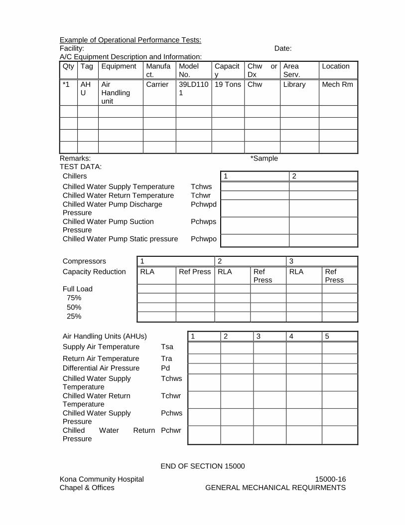
Kona Community Hospital 15000-16 Chapel & Offices GENERAL MECHANICAL REQUIRMENTS
Example of Operational Performance Tests: Facility: Date: A/C Equipment Description and Information:
Qty Tag Equipment Manufact.
Model No.
Capacity
Chw or Dx
Area Serv.
Location
*1 AHU
Air Handling unit
Carrier 39LD1101
19 Tons Chw Library Mech Rm
Remarks: *Sample TEST DATA:
Chillers 1 2
Chilled Water Supply Temperature Tchws
Chilled Water Return Temperature Tchwr
Chilled Water Pump Discharge Pressure
Pchwpd
Chilled Water Pump Suction Pressure
Pchwps
Chilled Water Pump Static pressure Pchwpo
Compressors 1 2 3
Capacity Reduction RLA Ref Press RLA Ref Press
RLA Ref Press
Full Load
75%
50%
25%
Air Handling Units (AHUs) 1 2 3 4 5
Supply Air Temperature Tsa
Return Air Temperature Tra
Differential Air Pressure Pd
Chilled Water Supply Temperature
Tchws
Chilled Water Return Temperature
Tchwr
Chilled Water Supply Pressure
Pchws
Chilled Water Return Pressure
Pchwr
END OF SECTION 15000

Kona Community Hospital 15250-1 Chapel & Offices INSULATION OF MECHANICAL SYSTEMS
SECTION 15250 - INSULATION OF MECHANICAL SYSTEMS
PART 1 - GENERAL
1.01 RELATED DOCUMENTS
A. Drawings and general provisions of the Contract, including General and Supplementary Conditions and Division 01 Specification Sections, apply to this Section.
1.02 GENERAL REQUIREMENTS
A. Section 15000, "General Mechanical Requirements", with the additions and modifications specified herein, applies to this section.
1. Manufacturer's Stamp or Label: Every package or standard container of insulation, jackets, cements, adhesives and coatings delivered to the project site for use must have the manufacturer's stamp or label attached giving name of manufacturer, brand and description of material. Insulation packages and containers shall be marked "asbestos-free".
2. Fire Resistance: Insulation, adhesives, vapor-barrier materials and other accessories, except as specified herein, shall be noncombustible. The materials shall have a flame-spread rating not more than 25 and a smoke-developed rating not more than 50 in accordance with NFPA 255, ASTM E 84-80 or UL 723.
a. Materials Tests: Test factory-applied materials assembled. Field-applied materials may be tested individually. Use no fugitive or corrosive treatments to impart flame resistance. UL label or satisfactory certified test report from an approved testing laboratory will be required to indicate that fire hazard ratings for materials proposed for use do not exceed those specified. Flame-proofing treatments subject to deterioration due to effects of moisture or high humidity are not acceptable.
b. Materials Exempt from Fire-Resistant Rating:
1) Nylon anchors 2) Treated wood inserts
1.03 SUBMITTALS
A. The items for which the submittal requirements of Section 15000, "General Mechanical Requirements", apply are as follows:
1. Manufacturer's Data:
a. Insulation b. Jackets c. Vapor-barrier materials d. Accessory-materials
2. Standards Compliance: Standards compliance labels are required on each container or package:

Kona Community Hospital 15250-2 Chapel & Offices INSULATION OF MECHANICAL SYSTEMS
a. Insulation
b. Jackets
c. Vapor-barrier materials
d. Accessory materials
1.04 DEFINITIONS
A. Finished Spaces: Habitation or occupancy spaces where rough surfaces are plastered, paneled or otherwise treated to provide a pleasing appearance.
B. Unfinished Spaces: Storage or work areas where appearance is not a factor, unexcavated spaces, crawl spaces, etc.
C. Concealed Spaces: Spaces between a ceiling and floor construction above or between double walls or furred-in areas; pipe and duct shafts, etc.
D. Exposed: Open to view inside the building. For example, pipe run through a room and not covered by other construction, is exposed.
E. Fugitive Treatments: Treatment of materials subject to deterioration due to aging, moisture, high humidity, oxygen, ozone and heat. Fugitive means entrapped materials that can cause deterioration e.g., solvents, water vapor, etc.
F. Outside: Open to view beyond the exterior side of walls, above the roof and unexcavated or crawl spaces, above or beneath pier floors, in tunnels or exposed on all sides in trenches connected or not connected to an exterior portion of a building.
1.05 PIPING REQUIRING INSULATION
A. Hot Water Piping.
B. Condensate Drain Piping
C. Chilled Water Piping
PART 2 - PRODUCTS
2.01 MATERIALS
A. Asbestos Prohibition: No asbestos containing materials or equipment shall be used under this section. The Contractor shall ensure that all materials and equipment incorporated in this project are asbestos free.
2.02 PIPING INSULATION
A. Insulation exterior shall be cleanable, grease resistant, non-flaking and non-peeling. Pipe insulation shall conform to the referenced publications and the specified temperature ranges and densities in pounds per cubic foot (pcf). Insulation for fittings and flanges shall be pre-molded, pre-cut or job-fabricated insulation of the same thickness and conductivity as used on adjacent piping.

Kona Community Hospital 15250-3 Chapel & Offices INSULATION OF MECHANICAL SYSTEMS
1. Interior Hot Water Piping: hot water piping shall be insulated with 1” fiberglass insulation with insulation jacket.
2. Exterior Hot Water Piping: hot water piping shall be insulated with 1” Pittsburgh Corning Foamglass insulation and finish with Johns Manville, Zeston 2000 PVC Jacket, 0.2 mils thick, or approved equal.
3. Condensate Drain Piping: All interior condensate drain piping shall be
insulated with 1” Rubatex or equal.
4. Chilled Water Piping Insulation (Supply and Return): All chilled water piping shall be insulated with Pittsburgh Corning Foamglas insulation. See Table 1 for insulation thickness requirements. Exterior chilled water piping shall be finished with Johns Manville, Zeston 2000 PVC Jacket, 0.2 mils thick, or approved equal.
2.03 DUCT INSULATION
A. All supply air and return duct work shall be wrapped with 1-1/2 inch thick duct wrap with vapor barrier. Owens Corning Fiberglass duct wrap with Foil-Scrim-Kraft facing or TVM Building Products reflective duct insulation with double layer of polyethylene bubbles, sandwiched between two layers of highly reflective aluminum sheets.
B. All air devices shall be fully insulated such that no metal portions of the diffuser are exposed in unconditioned areas. Provide molded fiberglass insulation diffuser blanket for 24”x24” lay-in modules. Diffuser blanket shall have foil back vapor barrier with 6.0 R-value.
2.04 INSULATION JACKETS
A. Vapor-Barrier Material: Material shall be resistant to flame and moisture penetration and not support mold growth. Provide vapor-barrier material on insulation in exposed locations with a white surface suitable for painting without sizing. Perm rating of .01.
2.05 ADHESIVES, SEALANTS AND COMPOUNDS
A. Shall be compatible with materials to which applied and suitable for the service.
1. Vapor-Barrier and Jacket Adhesive: Fire resistant type. Foster Products or approved equal.
2. Lagging Adhesive: Fire resistant type. Foster Products or approved equal.
3. Mineral Fiber Insulation Cement: ASTM C 195, thermal conductivity 0.85
max. at 200 degrees F mean when tested per ASTM C 177.
4. Bedding Compound and Joint Sealer: Fire resistant type. Foster Products or approved equal.

Kona Community Hospital 15250-4 Chapel & Offices INSULATION OF MECHANICAL SYSTEMS
5. Vapor-Barrier Coating: Fire resistant type. Perm rating of .05. Foster Products or approved equal.
2.06 ACCESSORIES
A. Staples: Corrosion-resistant outside-clinch type.
B. Anchor Pins: Provide anchor pins and speed washers recommended by the insulation manufacturer.
C. Glass Cloth and Tape: Textile Glass.
D. Vapor-Barrier Material Tape: Pressure-Sensitive adhesive backed. Arno or approved equal.
PART 3 - Execution
3.01 INSTALLATION
A. Install insulation system in accordance with manufacturer's recommendations using tradesman skilled in this trade and approved by the insulation manufacturer. Provide insulation products with a composite (insulation, jacket and adhesive) fire and smoke hazard rating as tested under ASTM E84, NFPA 255 and UL 723, not exceeding a flame spread of 25 and smoke developed of 50.
B. Pipe Insulation Thickness: Insulation thickness shall conform to Table 1.
Fluid
operating Temperature
Range and Usage
(degree F)
Insulation Conductivity Nominal Pipe or tube size
(inches)
Conductivity (BTU* in)/
(h*ft^2*degree F)
Mean Rating Temperature,
(degree F) < 1 1 to <
1.5 1.5 to
< 4 4 to <8 <=8
>350 0.32-0.34 250 4.5 5.0 5.0 5.0 5.0
251-350 0.29-0.32 200 3.0 4.0 4.5 4.5 4.5
201-250 0.27-0.30 150 2.5 2.5 2.5 3.0 3.0
141-200 0.25-0.29 125 1.5 1.5 2.0 2.0 2.0
105-140 0.21-0.28 100 1.0 1.0 1.5 1.5 1.5
40-60 0.21-0.27 75 0.5 0.5 1.0 1.0 1.0
<40 0.20-0.26 50 0.5 1.0 1.0 1.0 1.5
Table 1.
1. For insulation outside the stated conductivity range, the minimum thickness (T) shall be determined as follows: a. T = r [(1 + t/r)*K/k-1] where:
1) T= minimum insulation thickness
2) r= actual outside radius of pipe

Kona Community Hospital 15250-5 Chapel & Offices INSULATION OF MECHANICAL SYSTEMS
3) t= insulation thickness listed in the table for applicable fluid temperature and pipe size
4) K= conductivity of alternate material at mean rating temperature indicated for the applicable fluid temperature (Btu* in/h*ft^2* degree F)
5) k= the upper value of the conductivity range listed in the table for the applicable fluid temperature.
C. Expansion Clearances: At points where pipe will move during expansion and
contraction (expansion joints, Z-bends, expansion loops and ells), clearances between the pipe and encased insulation shall be sized to permit full pipe movement without cracking or damaging insulation and jacket.
D. Duct work and Duct work Accessories: Provide field-applied insulation to exterior of supply ducts, return ducts, and casings of HVAC units. Ensure full range of motion of equipment actuators. Modify insulation to avoid obstruction with valve handles, safety relief, and other such items. Install insulation with jackets drawn tight and cement down on longitudinal and end laps. Do not use scrap pieces where a full length section will fit.
3.02 FIELD INSPECTION
A. Visually inspect to insure that materials used conform with specifications. Inspect installation progressively for compliance with requirements.
3.03 ONE YEAR GUARANTEE
A. The Contractor shall warrant that all materials and equipment furnished under this section will be new and that all work will be of good quality, free from faults and defects and in conformance with Contract Documents for a guaranteed period of one year after the date of acceptance as specified.
END OF SECTION 15250
Kona Community Hospital 15300-1 Chapel & Offices WET PIPE SPRINKLER SYSTEM
SECTION 15300 -WET PIPE SPRINKLER SYSTEM PART 1 - GENERAL
1.01 RELATED DOCUMENTS
A. Drawings and general provisions of the Contract, including General and Supplementary Conditions and Division 01 Specification Sections, apply to this section.
1.02 SUMMARY
A. This Section includes the following: 1. Design and provide modifications to the existing wet pipe fire extinguishing
sprinkler system for uniform distribution of water by hydraulic design to afford complete fire protection coverage throughout the renovated area indicated on drawings.
2. Obtain and pay for all fees, permits, licenses, assessments and inspections required for this work. Schedule and coordinate required tests and inspections to accomplish the work in conformance with these specifications and drawings.
1.03 APPLICABLE PUBLICATION
A. The publications listed below form a part of this specification to the extent
referenced. The publications are referred to in the text by designation only.
B. American Society for Testing and Materials (ASTM) Publications 1. A 53-95 Pipe, Steel, Black and Hot-Dipped, Zinc-Coated Welded and
Seamless 2. A 795-95 Black and Hot-Dipped Zinc Coated (Galvanized) Welded and Seamless Steel Pipe for Fire Protection Use 3. B 75-81 Seamless Copper Tube 4. B 88-83 Seamless Copper Tube 5. B 251- Wrought Seamless Copper and Copper-Alloy.
C. American Water Works (A WW A) Publications: 1. CI04-90 Cement-Mortar Lining for Cast-Iron and Ductile-Iron Pipe and Fitting
for Water 2. C151-86 Ductile-Iron Pipe, Centrifugal1y Cast in Metal Molds or Sand-Lined Molds, for Water and Other Liquids 3. C601-86 Disinfecting Water Mains.
D. American Welding Society, Inc. (A WS) 1. A 5.8-81 Brazing Filler Metal
E. Copper Development Association Standards (CD A) 1. CDA 1.0 Flux
F. Factory Mutual (FM) Publication 1. Approval Guide, 2006 edition
G. National Fire Protection Association (NFPA) Publications:

Kona Community Hospital 15300-2 Chapel & Offices WET PIPE SPRINKLER SYSTEM
1. NFPA 13-2002 Installation of Sprinkler Systems
2. NFPA 25-2000 Inspection, Testing, & Maintenance of Water Based Fire
Protection Systems
3. NFPA 70-2002 National Electrical Code
4. NFP A 72-2002 National Fire Alarm Code
H. Underwriters' Laboratories, Inc. (UL) Publications: 1. Fire Protection Equipment Directory, 2006 edition
1.04 PERFORMANCE REQUIREMENTS
A. Scope: 1. The work includes the design and modifications to the existing wet pipe fire
extinguishing sprinkler system for uniform distribution of water by hydraulic design to afford complete fire protection coverage throughout the renovated area indicated on drawings.
2. Each system shall be provided with earthquake protection and shall include all materials, accessories, and equipment necessary to provide each system complete and ready for use. Design and install each system to give full consideration to blind spaces, piping, electrical equipment, ductwork, and all other construction and equipment to afford complete coverage in accordance with detailed drawings to be submitted for approval. Devices and equipment for fire protection service shall be listed by the Underwriters' Laboratories, Inc. or approved by Factory Mutual System. In the NFP A publications referred to herein, the advisory provisions shall be considered to be mandatory, as though the word "shall" had been substituted for "should" wherever it appears; reference to the "authority having jurisdiction" shall be interpreted to mean the Hawaii Insurance Bureau and the Building and Fire Departments. The work shall begin at the point indicated.
B. Qualifications of Installer:
1. Prior to submission of bid, submit data for approval by the WHFD AND/OR
PROJECT MANAGER, showing that the Contractor is a licensed fire protection contractor (C-20) and has successfully installed automatic fire extinguishing sprinkler systems of the same type and design as specified herein, or that he has a firm contractual agreement with a subcontractor having such required licensed experience. The data shall include the names and locations of at least two installations where the Contractor, or the subcontractor referred to above, has installed such systems. The contractor shall indicate the type and design of each system and certify that each system has performed satisfactorily in the manner intended for a period of not less than 18 months.

Kona Community Hospital 15300-3 Chapel & Offices WET PIPE SPRINKLER SYSTEM
C. Qualification of System Technician:
1. Installation drawings, shop drawing and as-built drawings shall be prepared, by or under the supervision of, an individual who is experienced with the types of works specified herein, and is currently certified by the National Institute for Certification in Engineering Technologies (NICET) as an engineering technician with minimum Level-III certification in the Fire Protection/Automatic Sprinkler System program. Contractor shall submit data for approval showing the name and certification of all involved individuals with such qualifications at or prior to submittal of drawings.
1.05 SUBMITTALS
A. Submittals shall be in accordance with Division 0 and Division 1 Specifications. Partial submittals will not be acceptable. Submit for approval six (6) complete sets of submittals as described below. Annotate descriptive data to show the specific model, type, and size of each item the Contractor proposes to furnish. Prepare working drawings on sheets not smaller than 24 by 36 inches, in accordance with the requirements for "Working drawings (Plans) as specified in NFPA 13, and include data essential to the proper installation of each system. Do not commence work until the design of each system and the various components have been approved. The Hawaii County, Building, Fire Departments and Hawaii Insurance Bureau will review and approve all submittals. Before work is commenced and after receiving the above approvals, submit to the State for approval complete sets of working drawings and calculations for the sprinkler system. Working drawings and calculations must be stamped by a licensed professional engineer.
1. Manufacturer's Data
2. Sprinklers
3. Spare sprinkler cabinet and sprinkler stoppers
4. Pipe, fittings, and mechanical couplings
5. Pipe hangers and supports
6. Earthquake sway bracing and seismic restraint
7. Flex-Head
B. Shop (Working) Drawings: 1. Sprinkler system layout conforming to NFPA 13.
C. Calculations:
1. Sprinkler system hydraulic calculations 2. Seismic bracing calculations

Kona Community Hospital 15300-4 Chapel & Offices WET PIPE SPRINKLER SYSTEM
D. Certificates of Compliance: 1. Contractor's material and test certificate per NFPA 13.
2. Pipe and fittings
E. Test Plan: A minimum of fifteen (15) days prior to the Preliminary Testing, the contractor shall submit a "Test Plan" which shall describe how the system will be tested. This shall include a step-by-step description of all tests and shall indicate type and location of test apparatus to be employed. Tests shall not be conducted until the test plan is approved by the WHFD AND/OR PROJECT MANAGER.
1. Publications: NFPA 25 - 2002, Standard for the Inspection, Testing, and
Maintenance of Water-Based Fire Protection Systems.
F. As-Built Drawings: Submit in accordance with Division 1. PART 2 - PRODUCTS
2.01 DESIGN OF SPRINKLER SYSTEM
A. Sprinkler System: Design of wet pipe fire extinguishing sprinkler system shall be by hydraulic calculations for uniform distribution of water over the design area and shall conform to NFPA 13 and to the requirements as specified herein.
1. Distribution of Water: Distribution shall be essentially uniform throughout the
area in which it is assumed the sprinkler heads will open. Variation in discharge from individual heads in the hydraulically most remote area shall be between 100 and 120 percent of the specified density.
2. Density of Application of Water: Size pipe to provide the specified density when the system is discharging the specified total maximum required flow. Application to horizontal surfaces below the sprinklers shall be as indicated on the drawings.
3. Sprinkler Discharge Area: Area shall be the hydraulically most remote area
as defined by NFPA 13. The design area shall be as indicated on the drawings.
B. Friction Losses: Calculate losses in pipe in accordance with the Hazen- Williams
formula with 'C' value of 120 for steel pipe, 140 for buried cement-lined ductile iron pipe and 150 for copper tubing.
1. Location of Sprinkler Heads: Heads in relation to the ceiling and walls and the
spacing of sprinklers shall not exceed that permitted by NFPA 13.
2.02 EQUIPMENT
A. Sprinkler Heads: Release element of each head shall be as indicated on the drawings or higher as suitable for the individual location where it is installed. Provide semi recessed quick response pendent sprinklers below finished

Kona Community Hospital 15300-5 Chapel & Offices WET PIPE SPRINKLER SYSTEM
ceilings. Provide brass quick response upright sprinkler in areas with no finished ceiling. Provide quick response brass sprinklers in the attic.
1. ABOVE GROUND PIPING SYSTEMS
B. Inspect, test and approve piping before burying, covering, or concealing. Provide
fittings for changes in direction of piping and for all connections. Make changes in piping sizes through reducing pipe fittings; the use of bushings will not be permitted. Welding shall be performed in the shop; field welding will not be permitted.
C. Pipe and Fittings:
1. Provide in accordance with NFPA 13, NFPA 14 and DBC STD 9-1 and 9-2. All piping and fittings shall be hot dipped galvanized steel. Pipe sizes less than 2.5 inches shall be Schedule 40, all other piping shall be minimum Schedule 10. Type L and K copper tubing shall not be permitted.
2. Fittings into which sprinkler heads, sprinkler head riser nipples, or drop nipples are threaded shall be welded, threaded, or grooved-end type. Use of plain-end fittings with mechanical couplings which utilize steel gripping devices to bite into pipe when pressure is applied will not be permitted. "Mechanical T", "Clamp T" or any other bolted branch outlet tees will not be permitted. Rubber gasketed grooved-end pipe and fittings with mechanical couplings shall be permitted in pipe sizes 1.25 inches and larger; fittings shall be UL listed or FM approved for use in sprinkler systems.
3. Provide an earthquake sway brace within 24 inches of each flexible coupling which is installed in horizon tar piping for purposes other than earthquake protection.
4. Flex-Head.
D. Pipe Hangers, Supports, and Earthquake Sway Bracing: Provide in accordance NFPA 13. Provide retaining straps on beam clamps. Provide branch line seismic restraint.
E. Valves: Provide valves as required by NFPA 13, and DBC STD 9-1, and of types approved for fire service. Gate valves shall open by counterclockwise rotation. Check valves shall be clear opening swing check type. Provide OS& Y valves as indicated.
F. Relief Valve: Provide an approved relief valve on gridded systems in accordance with NFPA 13.
G. Identification Signs: Attach properly lettered approved metal signs conforming to NFPA 13 to each valve and alarm device. Permanently affix hydraulic design data nameplates to the riser of each system.
H. Main and Auxiliary Drains: Provide drain piping to discharge at safe points outside each building or to sight cones attached to drains of adequate size to
Kona Community Hospital 15300-6 Chapel & Offices WET PIPE SPRINKLER SYSTEM
readily receive the full flow from each drain under maximum pressure. Provide auxiliary drains required by NFPA 13.
I. Pipe Sleeves: Provide where piping passes through walls, floors, roofs, and partitions. Secure sleeves in proper position and location. Provide sleeves of sufficient length to pass through entire thickness of walls, floors, roofs, and partitions. Provide not less than I-inch space between exterior of piping or pipe insulation and interior of sleeve. Firmly pack space with an approved firestopping material.
1. Sleeves in Masonry and Concrete, Walls, Floors and Roofs: Provide ASTM A 53, Schedule 40 or Standard Weight, zinc-coated steel pipe sleeves. Extend sleeves in floor slabs 3 inches above the finished floor.
2. Sleeves in Partitions and Other Than Masonry and Concrete Walls, Floors, and Roofs: Provide zinc-coated steel having weight of not less than 0.90 pounds per square foot.
J. Escutcheon Plates: Provide one piece or split hinge type metal plates for piping passing through floors, walls, and ceilings in exposed areas. Provide chromium-plated finish on plates; in finished areas. Provide paint finish on plates in unfinished areas. Securely anchor plates in place with setscrews or other approved positive means.
1. ELECTRICAL WORK: Electrical work is specified in "Electrical Work," except for control and fire alarm wiring in this section.
PART 3 - EXECUTION
3.01 INSTALLATION
A. Equipment, material, installation, and workmanship: Provide in accordance with NFPA 13, and UBC STD 9-1, except as modified herein. Install piping straight and true to bear evenly on hangers. Keep the interior of new and existing piping affected by the Contractor's operations thoroughly cleaned of water and foreign matter. Keep piping systems clean during installation by means of plugs or other approved methods. When work is not in progress, securely close open ends of piping and fittings so that water and foreign matter will not enter the pipes or fittings. Inspect piping before placing into position. Inspect, test, and approve piping before burying, covering, or concealing. Provide fittings for changes in direction of piping and for all connections. Make changes in piping sizes through tapered reducing pipe fittings; do not use bushings.
B. Pipe Hangers (Supports): Provide additional hangers to support the concentrated loads in piping between hangers, such as for flanged valves.
3.02 DISINFECTION
A. Disinfect the new water piping and existing water piping affected by Contractor's operations in accordance with AWWA C601. Fill the piping systems with solution containing minimum of 50 parts per million of available chlorine and allow

Kona Community Hospital 15300-7 Chapel & Offices WET PIPE SPRINKLER SYSTEM
solution to stand for minimum of 24 hours. Flush the solution from the systems with clean water until maximum residual chlorine content is not greater than 0.3 parts per million. Submit a certificate of completion for this work from a contractor experienced and licensed to do disinfecting work.
B. Obtain two water samples and submit them to a licensed laboratory for bacteriological testing. Water shall meet Federal water purity standards. Submit the laboratory report or a certification of satisfactory completion of disinfection. All costs of testing shall be borne by the contractor.
3.03 ELECTRICAL INSTALLATION
A. Comply with local ordinances and regulations of the Hawaii County as well as NFPA 70, and NFPA 72. Workmanship is subject to the approval of the WHFD AND/OR PROJECT MANAGER
3.04 FIELD PAINTING
A. Painting: Clean, pretreat, prime, and paint new sprinkler systems including valves, piping, conduit, hangers, miscellaneous metalwork, and accessories. Apply coatings to clean dry surfaces using clean brushes. Clean the surfaces to remove dust, dirt, rust and loose mill scale. Immediately after cleaning, provide the metal surfaces with one coat of pretreatment primer applied to a minimum dry film thickness of 0.3 mil, and one coat of primer applied to a minimum dry film thickness of one mil. Exercise care to avoid painting of sprinkler heads or protective devices. Remove materials which are used to protect sprinkler heads, while painting is in process, upon the completion of painting. Remove sprinkler heads which are painted and provide new clean sprinkler heads of the proper type. Provide primed surfaces with the following:
B. Sprinkler Systems in Unfinished Areas: Unfinished areas are defined as attic spaces, spaces above suspended ceilings, crawl spaces, pipe chases, and spaces where walls or ceiling are not painted or not constructed of prefinished material. Provide primed surfaces with one coat of red enamel applied to a minimum dry film thickness of one mil.
C. Sprinkler Systems in All Other Areas: Provide primed surfaces with two coats of paint to match adjacent surfaces, except provide valves and operating accessories with one coat of red enamel.
3.05 FIELD TESTING AND FLUSHING
A. Preliminary Test
1. Perform an air pressure leakage test for all sprinkler piping per NFPA 13, Paragraph 8-2.3, prior to hydrostatic testing. Hydrostatically test the sprinkler system at 200 psig or at 50 psi in excess of maximum pressure when the maximum will be in excess of 150 psi, for a period of two hours. Piping above suspended ceilings shall be tested, inspected and approved before installation of ceilings.
2. Flush sprinkler piping in accordance with NFPA 13. Continue flushing operations until water is clear, but for not less than 10 minutes.

Kona Community Hospital 15300-8 Chapel & Offices WET PIPE SPRINKLER SYSTEM
3. Test the alarms and other devices. Test the water flow alarms by flowing
water through the inspector's test connection.
4. When tests have been made completed and corrections made, submit a signed and dated certificate, similar to that specified in NFPA 13, with a request for a formal inspection and tests.
B. Formal Inspection and Tests: The Hawaii County, Building and Fire Departments will witness formal tests and approve all systems before they are accepted. Submit the request for formal inspection at least 15 days prior to the date for formal inspection is to take place. An experienced technician regularly employed by the sprinkler installer shall be present during the inspection. At this inspection, repeat any or all of the required tests as directed. Correct defects in the work provided by the Contractor, and make additional tests until it has been demonstrated that the systems comply with all contract requirements. Furnish appliances, equipment, electricity, instruments, connecting devices, and personnel for the tests. All necessary tests encompassing all aspects of system operation shall be made including the following, and any deficiency found shall be corrected and the system retested at no cost to the Hospital.
C. The existing fire sprinkler system protecting areas which are not in project scope shall be isolated from the new work required. Provide modifications to the existing system in a manner that does not interfere with the existing fire protection system outside of the project boundaries. If such interference is required, notify the facility in advance and provide fire watch as required.
3.06 INSTRUCTING OPERATING PERSONNEL
A. Upon completion of the work and at a time designated by the WHFD AND/OR PROJECT MANAGER, provide for a period of not less than 4 hours the services of experienced technicians regularly employed by the manufacturer of the sprinkler system to instruct the operating staff in the proper operation and maintenance of the equipment.
3.07 INSPECTION, MAINTENANCE, AND TESTING SERVICE AGREEMENT
A. The contractor shall include one year inspection, maintenance, and testing service agreement in the bid. The one year period shall begin at the date of acceptance. The agreement shall cover all labor, parts, insurance taxes, fees, and other incidental costs to inspect and test the system in accordance with NFPA 25 and the Hawaii County Fire Code. Inspection and testing of the system shall be conducted on a quarterly basis for a total, of four (4) visits during the one year period.
END OF SECTION 15300

Kona Community Hospital 15450-1 Chapel & Offices PLUMBING FIXTURES AND TRIM
SECTION 15450 - PLUMBING FIXTURES AND TRIM
PART 1 - GENERAL
1.01 RELATED DOCUMENTS
A. Drawings and general provisions of the Contract, including General and Supplementary Conditions and Division 01 Specification Sections, apply to this Section.
B. Section 15000, "General Mechanical Requirements", applies to this section with the additions and modifications specified herein.
1.02 WORK SPECIFIED IN THIS SECTION
A. All material, labor and equipment necessary for complete and operating interior plumbing fixtures and trim.
1.03 WORK SPECIFIED IN OTHER SECTIONS
A. Rough-In Piping: Section 15400, PLUMBING SYSTEM: BASIC MATERIALS AND METHODS.
1.04 SUBSTITUTIONS
A. Substitutions for products specified with equivalent models listed in the Plumbing "Blue Book" Index Creations Cross Reference need not pre-qualify. Other substitutions submit for approval in accordance with the Revised General Conditions and the Special Provisions of these Specifications.
1.05 SUBMITTALS
A. Submit under provisions of Section 15000 - GENERAL MECHANICAL REQUIREMENTS.
PART 2 - PRODUCTS
2.01 ASBESTOS PROHIBITION
A. No asbestos containing materials or equipment shall be used under this section. The Contractor shall ensure that all materials and equipment incorporated in the project as asbestos-free.
2.02 DOMESTIC PLUMBING FIXTURES AND TRIM
A. Substitutions for products specified with equivalent models shall be listed in the plumbing "Blue Book" index creations cross reference need not be pre-qualify. Other substitutions submit for approval in accordance with Section 15000 of these specification.
1. Sink – (S-1)

Kona Community Hospital 15450-2 Chapel & Offices PLUMBING FIXTURES AND TRIM
a. Elkay LRAD-191855 single bowl ADA Compliant sink, 18 ga. type 304 stainless steel, self-rim, 5-1/2" deep bowl, underside is fully undercoated, 3-1/2" drain opening. Two faucet holes, 4” centers.
b. Chicago model 895-317RGDABCP Deck mounted faucet. 5-1/4” rigid/swing spout. 2.2 gpm aerator. 4” wrist blade handle. Chrome plated.
c. Elkay Model LKAD-35 basket strainer with LKAD-OS off-set tail piece.
d. ProFlo Model No. PFPTP101 P-Trap with 1-1/4" inlet and 1-1/2" outlet with slip joint.
e. BrassCraft Model No. KTCR19C ¼” turn ball valve, ½” nom. Comp. x 3/8” OD comp.
f. ProFlo Model No. PF146323 S.S. braided flexible connections.
g. ProFlo Model No. PFE11 1-1/2” IPS chrome plated escutcheons.
h. ProFlo Model No. PFE7 5/8” OD copper escutcheons.
i. ProFlo Model No. PF202WH Lavatory Guard ADA conforming, wheelchair accessible lavatory under sink protective pipe cover.
j. Fixtures and installation to conform to ADAAG Section 606 Lavatories and Sinks.Elkay LRAD-1919-55-3 single bowl ADA Compliant sink, 18 ga. type 302 stainless steel, self-rim, 5-1/2" deep bowl, underside is fully undrecoated, 3-1/2" drain opening.
PART 3 - EXECUTION
3.01 EQUIPMENT SUBSTITUTIONS APPROVAL
A. Do not commence with installation until proposed equipment substitution submittals are approved
3.02 FIXTURE INSTALLATION
A. Set all plumbing fixtures in an approved workmanlike manner. Point up edges against wall with approved caulking.
B. Flanges at wall penetrations shall be flush against wall and shall not spin when rotated by hand.
C. Adjust equipment and plumbing fixtures and trim to operate properly and clean all fixtures just prior to final inspection.
END OF SECTION

Kona Community Hospital 15500-1 Chapel & Offices AUTOMATIC FIRE SPRINKLER SYSTEM
SECTION 15500 - AUTOMATIC FIRE SPRINKLER SYSTEM PART 1 - GENERAL
1.01 GENERAL CONDITIONS
A. As specified in Division 1 sections.
1.02 SCOPE
A. Remove existing wet pipe fire sprinkler system at the proposed project area. Keep the main FS wet pipe if it serves areas other than the project area.
B. Furnish wet pipe fire sprinkler, installed complete and ready to operate in accordance with the specifications and as shown on the drawings. Remove existing components where indicated
1.03 RELATED WORK SPECIFIED ELSEWHERE
A. Electrical- Division 16- ELECTRICAL
B. Section 16721- FIRE ALARM SYSTEM
1.04 DESIGN REQUIREMENTS
A. Scope:
1. Detailed design of the sprinkler system shall be made by a qualified licensed sprinkler system contractor. The system shall be hydraulically designed conforming to the requirements of NFPA 13 and all local requirements, except that all branch piping shall be sized for a maximum water velocity at 15 fps and all fire mains and risers shall be sized for a maximum velocity of 10 fps.
2. Each system shall be provided with earthquake protection and shall include all materials, accessories, and equipment necessary to provide each system complete and ready for use. Design and install each system to give full consideration to blind spaces, piping, electrical equipment, ductwork, and all other construction and equipment to afford complete coverage in accordance with detailed drawings to be submitted for approval. Devices and equipment for fire protection service shall be listed by the Underwriters' Laboratories, Inc. or approved by Factory Mutual System. In the NFP A publications referred to herein, the advisory provisions shall be considered to be mandatory, as though the word "shall" had been substituted for "should" wherever it appears; reference to the "authority having jurisdiction" shall be interpreted to mean the Hawaii Insurance Bureau and the Building and Fire Departments. The work shall begin at the point indicated.
B. Qualifications of Installer:
1. Prior to submission of bid, submit data for approval by the WHFD AND/OR PROJECT MANAGER, showing that the Contractor is a licensed fire
Kona Community Hospital 15500-2 Chapel & Offices AUTOMATIC FIRE SPRINKLER SYSTEM
protection contractor (C-20) and has successfully installed automatic fire extinguishing sprinkler systems of the same type and design as specified herein, or that he has a firm contractual agreement with a subcontractor having such required licensed experience. The data shall include the names and locations of at least two installations where the Contractor, or the subcontractor referred to above, has installed such systems. The contractor shall indicate the type and design of each system and certify that each system has performed satisfactorily in the manner intended for a period of not less than 18 months.
C. Qualification of System Technician:
1. Installation drawings, shop drawing and as-built drawings shall be prepared, by or under the supervision of, an individual who is experienced with the types of works specified herein, and is currently certified by the National Institute for Certification in Engineering Technologies (NICET) as an engineering technician with minimum Level-III certification in the Fire Protection/Automatic Sprinkler System program. Contractor shall submit data for approval showing the name and certification of all involved individuals with such qualifications at or prior to submittal of drawings.
1.05 GENERAL REQUIREMENTS
A. It is the intent of the plans and specifications to provide a complete installation.
Should there be omissions or discrepancies in the plans and specifications, the Contractor shall call the attention of the WHFD AND/OR PROJECT MANAGER to such omissions and discrepancies in advance of the date of bid opening so that the necessary corrections can be made. Otherwise the Contractor shall furnish and install the omissions or discrepancies as if the same were specified and provided for.
B. Regulatory Requirements and Standards:
1. All work shall be done in accordance with the latest edition of the International Plumbing Code, International Building Code, and all other applicable ordinances of the County of Hawaii.
2. Contractor shall obtain all permits, licenses, and certificates and pay for all fees.
3. National Fire Protection Association (NFPA) Publications:
a. NFPA 13-2002 Installation of Sprinkler Systems.
b. NFPA 25-2000 Inspection, Testing, & Maintenance of Water Based Fire Protection Systems.
c. NFPA 70-2002 National Electrical Code.
d. NFP A 72-2002 National Fire Alarm Code.

Kona Community Hospital 15500-3 Chapel & Offices AUTOMATIC FIRE SPRINKLER SYSTEM
C. Drawings and Specifications: The drawings and specifications are intended to cover the complete installation of systems to function as described. The omission of reference to any necessary item of labor or material shall not relieve the Contractor from providing such labor and material. Drawings do not attempt to show exact details of piping. Provide offsets as necessary to avoid local obstructions or interferences with other trades.
1. Contract Drawings: Mechanical plans are essentially diagrammatic, showing locations of pipes and other mechanical equipment. Where locations are not dimensioned, they are approximate, and before installing, Contractor shall study existing conditions and make installation in most logical manner. Fire mains, Fire Department connections, the areas covered and the criteria for use in hydraulic calculations are shown on the contract drawings. Other details applicable to the installation as a whole are also shown. The Contractor shall prepare complete working plans from hydraulic calculations prepared by personnel licensed by the City and County of Honolulu to perform this work. These plans may be used by the Contractor to submit for conditional approval of the Fire and Building Departments.
2. Shop Drawings: The Contractor shall submit 6 copies of shop drawings of equipment consisting of manufacturer's scale drawings, cuts or catalogs, including descriptive literature which shall indicate the construction, including material and physical dimensions, complete operating data and weight. Drawings shall also include scale drawings, of equipment, piping, foundations, etc., in plan and elevation, showing clearances between units, and relation of equipment, piping and equipment in space assigned. Shop drawings are required for all piping and equipment layout. Piping drawings shall indicate all connections, hangers, valves and specialties. The shop drawings and hydraulic calculations shall be reviewed and stamped by the registered engineer after being reviewed and stamped by the Hawaii Insurance Bureau. The plans and calculation shall clearly show the area of coverage, the occupancy hazard classification, the type of system and the location of maximum velocity, which is limited to 15 feet per second in any section of the branch lines, and 10 feet per second in the fire mains and riser.
3. As-Built Drawings: Maintain at project site a copy of drawings to record daily, any additions or changes. The Contractor shall keep at the job site a complete, neat and accurate record of all approved deviations from the contract drawings, shop drawings and specifications, indicating the exact location of all concealed lines, control valves, and other equipment which are different from the original drawings. These changes shall be recorded on prints of the drawings affected and the shop drawings. Autocad as-builts (hard copy and on CD) shall be submitted prior to final acceptance by WHFD AND/OR PROJECT MANAGER. These shall be in Autocad 2013 drawing file format.
1.06 SUBMITTALS
A. Submittals shall be in accordance with Division 0 and Division 1 Specifications. Partial submittals will not be acceptable. Submit for approval six (6) complete sets of submittals as described below. Annotate descriptive data to show the specific model, type, and size of each item the Contractor proposes to furnish.

Kona Community Hospital 15500-4 Chapel & Offices AUTOMATIC FIRE SPRINKLER SYSTEM
Prepare working drawings on sheets not smaller than 24 by 36 inches, in accordance with the requirements for "Working drawings (Plans) as specified in NFPA 13, and include data essential to the proper installation of each system. Do not commence work until the design of each system and the various components have been approved. The Hawaii County, Building, Fire Departments and Hawaii Insurance Bureau will review and approve all submittals. Before work is commenced and after receiving the above approvals, submit to the State for approval complete sets of working drawings and calculations for the sprinkler system. Working drawings and calculations must be stamped by a licensed professional engineer.
1. Manufacturer's Data: 2. Sprinklers 3. Spare sprinkler cabinet and sprinkler stoppers 4. Pipe, fittings, and mechanical couplings
5. Pipe hangers and supports
6. Earthquake sway bracing and seismic restraint.
7. Flex-Head
B. Shop (Working) Drawings:
1. Sprinkler system layout conforming to NFPA 13.
C. Calculations:
1. Sprinkler system hydraulic calculations.
2. Seismic bracing calculations.
D. Certificates of Compliance:
1. Contractor's material and test certificate per NFPA 13.
2. Pipe and fittings
E. Test Plan: A minimum of fifteen (15) days prior to the Preliminary Testing, the contractor shall submit a "Test Plan" which shall describe how the system will be tested. This shall include a step-by-step description of all tests and shall indicate type and location of test apparatus to be employed. Tests shall not be conducted until the test plan is approved by the WHFD AND/OR PROJECT MANAGER.
1. Publications: NFPA 25 - 2002, Standard for the Inspection, Testing, and Maintenance of Water-Based Fire Protection Systems.
F. As-Built Drawings: Submit in accordance with Division 1.

Kona Community Hospital 15500-5 Chapel & Offices AUTOMATIC FIRE SPRINKLER SYSTEM
1.07 WARRANTY AND CERTIFICATE
A. Warranty: All work and materials executed under this section shall be under warranty to be free from defects of materials and workmanship for one (1) year from date of final acceptance of project as a whole. Repairs and replacements necessitated by defects of this work, including labor, material and equipment shall be at no extra cost to the Owner. The Contractor shall be responsible for all damage to any part of the premises caused by leaks in the pipe or equipment furnished under this section. The Contractor is cautioned that any leaks or piping system failures due to any cause of location, workmanship or quality of material that will cause damage will be the responsibility of the Contractor.
PART 2 - PRODUCT
2.01 MATERIAL
A. All fire suppression equipment shall be selected from "List of Inspected Fire Protection Equipment and Materials", published annually by UL and shall bear UL approved stamp or label. All materials shall be new and of the best quality available in their respective kinds, free from all defects and shall be of the make and types specified or approved equal.
1. Pipe and Fittings: a. Sprinkler system piping above ground, shall be black steel pipe, Schedule
40, ASTM A 135.
b. Drain piping for sprinkler system risers shall be copper tubing, ASTM B88, Type L.
(OR)
c. Fittings for steel pipe shall be black cast-iron, screwed, suitable for 175
psi wwp -- Grinnell Co., Crane Co., Stockham Pipe Fittings Co., or approved equal. At the Contractor's option, fittings shall be grooved-pipe fittings, with grooved-pipe couplings, Vitaulic or approved equal.
B. Valves:
1. Valves shall be screwed or flanged, iron body with bronze disk for steel pipe and shall be UL approved.
2. Check valves shall be iron body bronze swing check, renewable seat rings, bolt cover for 175 psi wwp, flanged
C. Sprinkler Heads: Sprinkler heads shall be 1/2 inch, automatic, closed type of temperature rating, as indicated or as required in NFPA Pamphlet No. 13. Temperature rating of heads shall be selected such that the temperature rating is at least 50ºF above the highest ambient temperature to be encountered. Sprinkler heads in unfinished areas such as mechanical rooms and utility rooms shall be upright or inverted type, as appropriate to the location of installation,

Kona Community Hospital 15500-6 Chapel & Offices AUTOMATIC FIRE SPRINKLER SYSTEM
with standard factory finish. Sprinkler heads in spaces with finished ceilings shall be chrome plated, except as indicated. Provide UL and FM approved sprinkler heads for the application described, manufactured by Viking or Gem, comparable to models listed.
1. Standard Upright and Pendant: Use Gem Model TY-FRL with exposed
piping installations.
2. Sidewall: Heads shall be chrome, quick response Gem Model TY-FRL.
3. Extended Coverage Horizontal Sidewall: Heads shall be chrome, Viking Model "M".
4. Concealed Type: Head shall be recessed into ceiling and concealed by a flat
cover plate, Gem Model RFII. Color shall be as selected by Architect.
5. Flush Type: Head shall have all internal parts concealed by a cover plate, Gem Model TY-QRF.
6. Recessed Pendant: Heads shall be chrome with chrome plated adjustable
escutcheon, Gem Model TY-B.
7. Provide guards on all sprinkler heads which are so located as to be subject to mechanical injury in either the upright or pendant position.
8. At a convenient location for Owner, provide a sprinkler cabinet containing a
reserve supply of sprinkler heads of each type and two wrenches necessary for installing them. Quantity shall be as specified in NFPA 13.
D. Firestop: Link Seal Model FD or FS with pipe sleeve or hole drilled floor or wall penetration. Other materials may be submitted to the WHFD AND/OR PROJECT MANAGER for approval.
E. Valve Seals, Tags, Charts:
1. Signs: Provide identification signs of standard design, fasten securely at designated locations as per NFPA No. 13.
2. Tags: Provide brass tags about 2 inches diameter. Stamp with designating numbers, secure with 12 gage copper wire to spindle of all control valves.
PART 3 - EXECUTION
3.01 INSTALLATION AND WORKMANSHIP
A. The installation shall be accomplished by a qualified, licensed Contractor recognized as a fully experienced specialist in automatic fire sprinkler systems, and in conformance with NFPA No. 13. All piping shall be drip-tight and properly installed to be free of vibration, pounding, or objectionable noise. Provide seismic bracing of all fire sprinklers piping per NFPA 13.
Kona Community Hospital 15500-7 Chapel & Offices AUTOMATIC FIRE SPRINKLER SYSTEM
3.02 SCREW JOINTS
A. All piping shall be accurately cut to measurements established by the Contractor and shall be worked into place without springing or forcing. In any situations where bending of pipe is required, such bending shall be accomplished through the use of a standard pipe-bending template. Pipe compound shall be applied to male threads only. Drips and drains shall be installed where necessary and shall discharge outside of the building. In no case shall a direct connection be made to any component of the sewer system.
3.03 MECHANICAL JOINTS
A. Installation of mechanical joints for cast-iron water pipe and fittings shall conform to AWWA Clll and NFPA No. 24.
3.04 CORROSION PROTECTION
A. Provide dielectric unions and dielectric flanges between dissimilar metals. Provide neoprene pads between pipe and pipe hangers of dissimilar metals.
3.05 SPRINKLER HEADS
A. Shall be spaced so as to provide the required discharge density and coverage, and in no case shall the spacing exceed the NFPA requirements for proper hazard occupancy. Pendant heads, where required, shall be installed as shown in NFPA No. 13.
3.06 INSPECTOR'S TEST VALVES
A. Shall be installed, supplied from the highest and most remote part of each system in relation to the riser assembly and to a drain. Test valves shall be conveniently accessible.
3.07 DRAIN AND TEST CONNECTIONS
A. Install horizontal piping graded to low points in manner to make it possible to test and empty entire system. Provide valves and piping of sizes and in locations as indicated or as required by NFPA No. 13.
B. Extend drain valves' discharge pipes to points indicated or the nearest drain line. Terminate pipes so that discharge will be visible.
C. Provide flushing connections at end of cross mains, consisting of capped nipple same diameter as pipe but not larger than 2 inches.
3.08 SUPPORTS, HANGERS, INSERTS
A. Support sprinkler piping from building structure by means of hangers, inserts,
other supports, as per requirements in NFPA No. 13.

Kona Community Hospital 15500-8 Chapel & Offices AUTOMATIC FIRE SPRINKLER SYSTEM
3.09 PIPE SLEEVES, ESCUTCHEONS
A. Furnish and set sleeves to accommodate pipes passing thru foundations, walls, floors, partitions. Provide escutcheons at exposed finished surfaces pierced by pipes.
B. Extend sleeves above finished floor and pack space between pipe and sleeve as
recommended in NFPA No. 13.
C. Firestops shall be installed as recommended by the manufacturer.
3.10 PAINTING
A. Painting: Clean, pretreat, prime, and paint new sprinkler systems including valves, piping, conduit, hangers, miscellaneous metalwork, and accessories. Apply coatings to clean dry surfaces using clean brushes. Clean the surfaces to remove dust, dirt, rust and loose mill scale. Immediately after cleaning, provide the metal surfaces with one coat of pretreatment primer applied to a minimum dry film thickness of 0.3 mil, and one coat of primer applied to a minimum dry film thickness of one mil. Exercise care to avoid painting of sprinkler heads or protective devices. Remove materials which are used to protect sprinkler heads, while painting is in process, upon the completion of painting. Remove sprinkler heads which are painted and provide new clean sprinkler heads of the proper type. Provide primed surfaces with the following:
B. Sprinkler Systems in Unfinished Areas: Unfinished areas are defined as attic spaces, spaces above suspended ceilings, crawl spaces, pipe chases, and spaces where walls or ceiling are not painted or not constructed of prefinished material. Provide primed surfaces with one coat of red enamel applied to a minimum dry film thickness of one mil.
C. Sprinkler Systems in All Other Areas: Provide primed surfaces with two coats of
paint to match adjacent surfaces, except provide valves and operating accessories with one coat of red enamel.
3.11 INSPECTION AND TESTS
A. Furnish WHFD AND/OR PROJECT MANAGER with results of all tests conducted under this section.
1. Water System: When the roughing-in is completed and/or the system completed, the entire fire protection water piping system shall be tested at a hydrostatic pressure of not less than 200 pounds per square inch gauge, and proved tight at this pressure for not less than two (2) hours in order to permit inspection of all joints. Where a portion of the water piping system is to be concealed before completion, this portion shall be tested separately as specified for the entire system.

Kona Community Hospital 15500-9 Chapel & Offices AUTOMATIC FIRE SPRINKLER SYSTEM
2. Air Test: In buildings that are occupied or the interior areas have been completed, the Contractor shall conduct a test with air pressure of at least 40 PSI allowed to stand for at least 24 hours. The standard water test shall be conducted after the Contractor is satisfied that the air test shows no leaks in the system.
3. Defective Work: If inspection or test shows defects, such defective work or
material shall be replaced or repaired as necessary and inspection and tests repeated. Repairs to piping shall be made with new materials. No caulking of screwed joints or holes will be acceptable.
4. Cleaning and Adjusting: Equipment, pipes, valves, and fittings, shall be
cleaned of grease, metal cuttings, and sludge that may have accumulated from operation of the system during the test. Any stoppage, discoloration, or other damage to the finish, furnishings, or parts of the building, due to the Contractor's failure to properly clean the piping system, shall be repaired by the Contractor without additional cost to the Owner. The system shall be flushed as required by the NFPA.
B. Formal Inspection and Tests: The Hawaii County, Building and Fire Departments
will witness formal tests and approve all systems before they are accepted. Submit the request for formal inspection at least 15 days prior to the date for formal inspection is to take place. An experienced technician regularly employed by the sprinkler installer shall be present during the inspection. At this inspection, repeat any or all of the required tests as directed. Correct defects in the work provided by the Contractor, and make additional tests until it has been demonstrated that the systems comply with all contract requirements. Furnish appliances, equipment, electricity, instruments, connecting devices, and personnel for the tests. All necessary tests encompassing all aspects of system operation shall be made including the following, and any deficiency found shall be corrected and the system retested at no cost to the Hospital.
3.12 CLEAN UP
A. Debris shall not be allowed as a result of this work. Upon completion of this work, remove all debris and excess materials, tools, etc., resulting from this work from the job site and leave the location of this work broom-cleaned in an acceptable manner as approved by the WHFD AND/OR PROJECT MANAGER.
END OF SECTION 15500

Kona Community Hospital 15700-1 Chapel & Offices HYDRONIC PIPING, EQUIPMENT, AND ACCESSORIES
SECTION 15700 - HYDRONIC PIPING, EQUIPMENT, AND ACCESSORIES PART 1 - GENERAL 1.01 GENERAL CONDITIONS
A. Section 15000, "General Mechanical Requirements", applies to this section with
additions and modifications specified herein. The piping systems as specified in this section include chilled water; tubing flanges; bolting; gaskets; valves; fittings; pressure containing assemblies; flow measuring equipment and flow control equipment.
1.02 SUBMITTALS
A. Manufacturer's Literature and Data: 1. Piping and Fittings, Gaskets, Valves and Piping Accessorie
2. Pumps and Heat Exchanger
3. Hangers and Supports
B. Operation and Maintenance Manuals:
1. Piping Diagrams and Codes
2. Pumps and Heat Exchanger
C. Certified Laboratory Test Reports:
1. Valves
D. Shop Drawings:
1. Piping Installation
2. Pumps and Heat Exchanger
E. Welding:
1. Welding Procedure: Before any welding is performed, submit three copies of
this welding procedure specification for all metals included in the work, together with proof of its qualifications as outlined in ANSI B31.1.
2. Performance Qualification Record: Before any welder or operator performs any welding the Contractor shall submit to the Owners Representative three copies of the Welder's Performance Qualification Record in conformance with ANSI B31.1 showing that the welder was tested under the approved procedure specification submitted by the Contractor. In addition the Contractor shall submit each welder's assigned number, letter or symbol which shall be used to identify the work of the welder which shall be affixed immediately upon completion of the weld. Welders making defective welds after passing a qualification test shall be required to take a re-qualification

Kona Community Hospital 15700-2 Chapel & Offices HYDRONIC PIPING, EQUIPMENT, AND ACCESSORIES
test. Welders failing the re qualification tests will not be permitted to work under this contract.
3. Previous Qualifications: Welding procedures, welders and welding operators previously qualified by test may be accepted for this contract without re qualification subject to approval provided that all the conditions specified in ANSI B31.1 are met before a procedure can be used.
F. Brazing: Brazing Procedure: Before any brazing is performed, submit three copies of this brazing procedure specification for all metals included in the work, together with proof of its qualifications as outlined in ANSI/AWS B2.2.
1.03 CORROSION PREVENTION OF FERROUS METALS
A. Expose for 125 hours in a salt spray fog test, except equipment located outdoors shall withstand 500 hours. The salt spray fog test shall be in accordance with ASTM B117 using a 5 parts by weight (plus or minus 1) of sodium chloride in 95 parts of distilled water or water containing not more than 200 parts per million of total solid sodium chloride solution. Immediately after completion of the test the coating shall show no signs of blistering, wrinkling or cracking, no loss of adhesion and the specimen shall show no signs of rust creepage beyond 1/8 inch on either side of the scratch mark. The film thickness of the factory coating or paint system applied on the equipment shall not be less than the film thickness used as the test specimen.
1.04 ROTATING EQUIPMENT SAFETY
A. Couplings, Motor Shafts, Gears and other exposed rotating or rapidly moving parts shall be fully guarded in accordance with OSHA 1910.219. The guards shall be cast iron or expanded metal. Guard parts shall be rigid and suitably secured and shall be readily removable without disassembling the guarded unit.
1.05 WELDING AND CUTTING
A. ANSI Z49.1.
PART 2 - PRODUCTS 2.01 WATER PIPING, FITTINGS AND ACCESSORIES
A. Materials and dimensions in accordance with ANSI B31.1 Water Piping Systems
as used in this paragraph include chilled water piping systems. Piping systems shall be compatible with system fluids and capable of withstanding the operating pressures and temperatures. 1. Chilled Water Piping:
a. Provide seamless Schedule 40 black steel pipe conforming to ASTM A53.
Fittings shall be butt-weld wrought carbon steel conforming to ASRM A234 and ASME B16.9, or flanged type conforming to ANSI B16.5. Convoluted steel flanges conforming to ASME Code Section 8 may be used in lieu of ANSI B16.5 flanges.
Kona Community Hospital 15700-3 Chapel & Offices HYDRONIC PIPING, EQUIPMENT, AND ACCESSORIES
b. At Contractor's option, provide Type "K" hard-drawn copper tube, ASTM B-88, with brazed joints for the pipe size 3 inches and smaller. Copper fittings shall be wrot copper solder-type conforming to ANSI B16.22. Joints for solder-type fittings shall be brazed using Canfield Sil-Can 15 silver brazing alloy conforming to AWS CcuP-2 and Sil-Can “White Cream” brazing flux. Install copper tube and fittings in accordance with CDA (Copper Development Association) 404/O-RR guidelines.
2. Flanges: The raised faces shall be removed when used with flanges having
a flat face. a. Steel Flanges: ANSI B16.5 forged steel, welding type conforming to
ASME Code Section 8. Do not use convoluted flanges. Stockham, Walworth or approved equal.
3. End Connections: Steel Piping: Steel piping 2 1/2 inches and larger shall be flanged or butt welded. a. Bolting of Flanges: Material used for bolts and studs shall conform to
ASTM A307, Grade B and material for nuts shall conform to ASTM A194, Grade 2. Dimensions of bolts, studs and nuts shall conform to ANSI B18.2.1 and ANSI B18.3.2 with threads conforming to ANSI B1.1 coarse type with Class 2A fit for bolts and studs and Class 2B for nuts. Bolts or studs shall extend completely through the nuts and may have reduced shanks of a diameter not less than the diameter at root of threads. Carbon steel bolts shall have American Standard regular square or heavy hexagon heads and shall have American Standard heavy semi-finished hexagonal nuts.
b. Gaskets: ASTM D 2000, fluorinated elastomers, suitable for the pressure and temperature ranges encountered and compatible with grooves in flange faces.
c. Butt Weld Joints: Shall conform to ANSI B31.1. The use of backing rings
shall conform to ANSI B31.1. Ferrous rings shall be of good welding quality and shall not exceed 0.05 percent sulfur; for alloy pipe, backing rings shall be of material compatible with the chemical composition of the parts to be welded and preferably of the same composition. Backing rings shall be of the continuous machined or split band type.
d. Socket Weld Joints: Shall conform to ANSI B31.1.
e. All connections to mechanical equipment shall be flanged connections.
4. Valves: Gate, Special and Related Equipment shall conform to the following
paragraphs. End connections shall conform to paragraph "End Connections". Valves shall have rising stems and shall open when turned counterclockwise. a. Ball Valves: Use full port ball valves with threaded/flanged ends for
isolation/shutoff. Provide stem extensions, as necessary, to accommodate piping insulation. Operating pressure shall not exceed 80% of the valve pressure class. Use 600 WOG – 150 SWP class, forged brass, ball valves with threaded ends.

Kona Community Hospital 15700-4 Chapel & Offices HYDRONIC PIPING, EQUIPMENT, AND ACCESSORIES
b. Drain Valves: Shall be gate valves, bronze, 150 pound class. Shall not
be smaller than 3/4 inch nominal pipe size, shall have threaded ends and shall be provided with hose nipple adapters for connecting a hose to lead to a convenient floor drain. The valves shall be manually operated. Stockham, Nibco, or approved equal. Provide at low points on system whether shown on drawings or not.
c. Air Vent Valves: Shall be Manually Operated General Service Type and Automatic Type. The automatic type air vent valves shall be of the ball float type. The valves shall be provided with cast iron bodies, 300 series corrosion resistant steel float, linkage and removable seat of hardened corrosion resistant steel. Manual vent valves shall be gate valves, bronze, 150 pound class. Valves shall be suitable for hot or cold water service and 125 psi working pressure. The valves shall be 3/4 inch pipe size for water mains and 1/2 inch pipe size, minimum, for all other applications. Air vent valves shall be provided at all high points in the water piping system or as indicated.
d. Check Valve:
1) Cast Iron Check Valves 2 1/2 Inches and Larger: Valves shall be Class 150 with bronze trim. Provide non slam, eccentric disc type for centrifugal pump discharge service.
2) Check valve 2-inches and smaller: Valves shall be of Class 125, thread or solder ends, body and caps shall be of ASTM B-62 cast iron bronze composition swing type disc.
5. Miscellaneous Components for Piping System:
a. Flexible Connector: Shall be for water service and shall be flanged
neoprene type with braided stainless steel outer casing and bolted steel control rods. Materials shall be of the type recommended by the manufacturer for use with chilled water. Mason or approved equal.
b. Y-Type Strainer: Bronze body, 20 mesh stainless steel screen, 125 psi working pressure. Provide with blow-off valve. Mueller Steam Specialty Co. or approved equal.
6. Dielectric Insulating Fittings.
a. Insulating unions or flanges shall be provided at locations described
herein unless noted otherwise.
b. A shutoff valve shall be provided locally, upstream of dielectric insulating fittings, so that repairs can be made easily on these fittings.
c. Locations requiring insulating couplings or flanges are as follows:
1) At connection points where copper water lines connect to steel
domestic water heater tanks.

Kona Community Hospital 15700-5 Chapel & Offices HYDRONIC PIPING, EQUIPMENT, AND ACCESSORIES
2) At points in water lines where ferrous and other dissimilar metallic pipes are connected together.
3) In metallic water and gas service connections into each building within
5 feet of the building wall. Install adjacent to the shutoff valve or cock, and aboveground where possible.
4) Where steel or cast iron pipe in the ground connects to copper or
brass piping above the ground, the transition from steel or cast iron pipe to the copper or brass pipe shall be made aboveground in an accessible location.
5) Where copper or brass piping is connected to steel or cast iron piping
and the connection is buried in the ground, the connection shall be covered with a protective coal tar tape wrap extending outward at least 5 feet on pipes, from the point of connection. The tape shall be Protecto Wrap No. 200, or equal. A primer, specifically designed for use with the tape, shall be used. The piping shall be thoroughly cleaned before tape or primer is applied.
B. Materials and dimensions in accordance with ANSI B31.1 Water Piping Systems
as used in this paragraph include salt water piping systems. Piping systems shall be compatible with system fluids and capable of withstanding the operating pressures and temperatures. 1. All PVC Schedule 80 pipe and fittings shall be produced by Spears®
Manufacturing Company from PVC Type I cell classification 12454, conforming to ASTM Standard D 1784, or approved equal. All PVC injection molded Schedule 80 fittings and extruded pipe shall be Certified for potable water service by NSF International. All Schedule 80 fittings shall be manufactured in strict compliance to ASTM D 2467 and Schedule 80 pipe shall be manufactured in strict compliance to ASTM D 1785. All fabricated fittings shall be produced in accordance with Spears® General Specifications for Fabricated Fittings. All PVC flanges shall be designed and manufactured to meet CL150 bolt pattern per ANSI Standard B16.5 and rated for a maximum internal pressure of 150 psi, non-shock at 73° F.
2. Ball Valves: Utility sealed unit type constructed from PVC Type I, ASTM D 1784 Cell Classification 12454 or CPVC Type IV, ASTM D 1784 Cell Classification 23447. All O-rings shall be EPDM. All valves shall have Safe-T-Shear® stem and removable Polypropylene handle. All valves shall be certified by NSF International for use in potable water service. All valves shall be pressure rated at 150 psi for water at 73° F, as manufactured by Spears® Manufacturing Company, or approved equal.
2.02 PLATE AND FRAME HEAT EXCHANGER (HX-1)
A. General
1. All materials shall meet or exceed all applicable referenced standards,
federal, state and local requirements, and conform to codes and ordinances of authorities having jurisdiction.
Kona Community Hospital 15700-6 Chapel & Offices HYDRONIC PIPING, EQUIPMENT, AND ACCESSORIES
2. Furnish and install plate and frame heat exchangers designed with manufacturer's standard fouling allowance and guaranteed to perform to the capacities and pressure drops at the fluid temperatures and flow rates as scheduled. The maximum allowable water pressure drops for the cold and hot sides shall not exceed 10psi.
3. The plate & frame heat exchanger shall be shipped completely assembled,
free standing, pressure tested at factory, flushed and cleaned and dried, ready for connection at jobsite.
4. Where field erection is required, the manufacturer shall pressure test units at
factory, flush and clean and dried, then knock-down and properly crated and marked for erection at jobsite. Manufacturer’s supervision will be required at jobsite and warranties as factory assembled units remain in effect.
5. Units shall be pressure rated for 150 psig cold (distribution system side) and 150 psig hot (building side).
6. The plate unit shall be designed to withstand full design pressure in each circuit independently The entire unit shall be hydrostatically tested according to ASME Code, Sect. VIII, Div. 1 for 1.3 x design pressure at maximum working temperature.
B. Manufacturers
1. APV Crepaco, Inc.
2. Tranter PHE, Inc.
3. ITT Bell & Gossett.
4. Alfa – Laval, Inc.
5. Paul Mueller Company (Accu-Therm).
C. Frame Components
1. The frame shall be a single pass design with all inlet and outlet connections
on the fixed cover.
2. The fixed and movable covers shall be of sufficient thickness for design pressure and code requirements and shall have no welded reinforcements or stiffeners.
3. The frame assembly shall be of bolted construction to allow field erection on
the site, where required. Welded frame assemblies are not acceptable.
4. The movable cover shall be provided with steel roller bearing for units greater than 50” in height (from bottom of feet) and for units with port sizes 3” and larger. This allows the removable cover to be moved without additional rigging or handling equipment.
5. The frame assembly’s upper carry and lower guide bars shall be designed to
allow for minimum of 25% plate expansion.

Kona Community Hospital 15700-7 Chapel & Offices HYDRONIC PIPING, EQUIPMENT, AND ACCESSORIES
6. The portion of the top carrying bar system which comes in contact with the
plates shall be stainless steel to prohibit corrosion and facilitate movement of plates. Painted or plated surfaces are not permitted.
7. Provide carbon steel frames, cleaned of mill scale, primed and painted with
two (2) coats of baked epoxy enamel.
8. Provide a minimum of two (2) lifting lugs per frame for units with 6 inch ports and larger and designed for lifting assembled flooded unit’s flooded weight.
D. Plates 1. Provide titanium heat transfer plates with designed to provide support to
adjacent plates to allow pressurization of each circuit to a full differential with no pressure on the adjacent plate channels without deformation of the heat transfer plates.
2. All plates shall be permanently marked to identify quality and material.
3. All ferrous materials in contact with fluids on the hot and cold sides shall be titanium.
4. Each heat transfer plate shall have built-in self-aligning system to accurately
locate plates in the frame assembly and prevent lateral movement and maintain maximum gasket contact under pressure.
5. Plates shall be reinforced on the upper and lower mounting slots to avoid
bending on the plates.
6. Overall plate area should be increased by 10% to account for fouling that will occur as the heat exchanger is being used.
7. Heat transfer plates shall include tapered gasket grooves and shall receive
standard IIB finish.
8. Provide OSHA compliant aluminum splashguard over channel plate rack and shroud around plate pack.
E. Gaskets
1. Gaskets shall be one piece molded nitrile (NRB) rubber compatible with the
fluid shown on the plan and schedule and suitable for working temperature up to 250 degrees F. Gaskets shall fit around the heat transfer area and the port holes without the need for glue or adhesive.
2. Gasket shall be permanently marked to identify quality and material.
3. Gasket to have reliving grooves in the double gasketed areas to prevent any cross-contamination between the hot and cold fluids and cause leak to flow outside of unit.
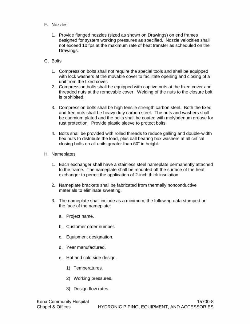
Kona Community Hospital 15700-8 Chapel & Offices HYDRONIC PIPING, EQUIPMENT, AND ACCESSORIES
F. Nozzles 1. Provide flanged nozzles (sized as shown on Drawings) on end frames
designed for system working pressures as specified. Nozzle velocities shall not exceed 10 fps at the maximum rate of heat transfer as scheduled on the Drawings.
G. Bolts 1. Compression bolts shall not require the special tools and shall be equipped
with lock washers at the movable cover to facilitate opening and closing of a unit from the fixed cover.
2. Compression bolts shall be equipped with captive nuts at the fixed cover and threaded nuts at the removable cover. Welding of the nuts to the closure bolt is prohibited.
3. Compression bolts shall be high tensile strength carbon steel. Both the fixed and free nuts shall be heavy duty carbon steel. The nuts and washers shall be cadmium plated and the bolts shall be coated with molybdenum grease for rust protection. Provide plastic sleeve to protect bolts.
4. Bolts shall be provided with rolled threads to reduce galling and double-width
hex nuts to distribute the load, plus ball bearing box washers at all critical closing bolts on all units greater than 50” in height.
H. Nameplates
1. Each exchanger shall have a stainless steel nameplate permanently attached
to the frame. The nameplate shall be mounted off the surface of the heat exchanger to permit the application of 2-inch thick insulation.
2. Nameplate brackets shall be fabricated from thermally nonconductive materials to eliminate sweating.
3. The nameplate shall include as a minimum, the following data stamped on
the face of the nameplate:
a. Project name.
b. Customer order number.
c. Equipment designation.
d. Year manufactured.
e. Hot and cold side design.
1) Temperatures. 2) Working pressures.
3) Design flow rates.

Kona Community Hospital 15700-9 Chapel & Offices HYDRONIC PIPING, EQUIPMENT, AND ACCESSORIES
4) Pressure differentials at design flow rates.
5) All information required for plate pack compression.
6) Model and serial numbers. 2.03 THERMOMETERS
A. Seven inch aluminum case, Well Threaded and Seal Welded or Seal Brazed,
Range 0 degrees to 100 degrees F., Standard Stem, Adjustable angle. Scale and temperature ranges shall be suitable for the intended service. Thermometers shall be of the organic liquid type as approved. Trerice, Marshalltown or approved equal. Where installed on salt water piping, provide corrosion resistant thermometers constructed of 316 Stainless Steel, Weiss Instruments or approved equal.
2.04 PRESSURE GAUGES
A. Aluminum case, 4 1/2 inch dial size for water. The scale ranges, graduations, figure intervals and type of mounting shall be selected specifically for the intended service. The gauge shall be of a design that is readable from the floor. For pumps, provide compound type gauges as indicated on the drawings. Trerice, Marshalltown or approved equal. Where installed on salt water piping, provide corrosion resistant pressure gauges constructed of 316 Stainless Steel, Weiss Instruments or approved equal.
2.05 AIR WATER SEPARATOR
A. Furnish and install a shown on plans an external air separation unit. The unit shall have 4" (NPT) inlet and outlet connections and strainer removal connection where specified. The removable strainer shall be of stainless steel with 3/16" diameter perforations and a free area of not less than five times the cross-sectional area of the connecting pipe. Installer shall remove and clean strainer after 24 hours operation and after 30 days operation. Unit shall have separate top fittings for connection to system expansion tank and for air vent. There shall be a bottom connection for blowdown cleaning. Unit shall be constructed in accordance with the ASME boiler and pressure vessel code and stamped 125 psig design pressure. Each air separation unit shall be Taco, Bell & Gosset or approved equal.
2.06 EXPANSION TANK
A. ASME Pressure Vessel, recharged bladder-type tank for 125 psi working pressure. Bell & Gossett series B, Taco or approved equal.
2.07 FLOW CONTROL VALVES
A. Griswold flow control valve with fixed flow rate as indicated or approved equal.
2.08 WATER TREATMENT SYSTEM
A. Provide water treatment for the chilled water system.
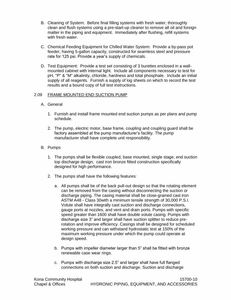
Kona Community Hospital 15700-10 Chapel & Offices HYDRONIC PIPING, EQUIPMENT, AND ACCESSORIES
B. Cleaning of System: Before final filling systems with fresh water, thoroughly clean and flush systems using a pre-start-up cleaner to remove all oil and foreign matter in the piping and equipment. Immediately after flushing, refill systems with fresh water.
C. Chemical Feeding Equipment for Chilled Water System: Provide a by-pass pot
feeder, having 5-gallon capacity, constructed for seamless steel and pressure rate for 125 psi. Provide a year’s supply of chemicals.
D. Test Equipment: Provide a test set consisting of 3 burettes enclosed in a wall-
mounted cabinet with internal light. Include all components necessary to test for pH, "P" & "M" alkalinity, chloride, hardness and total phosphate. Include an initial supply of all reagents. Furnish a supply of log sheets on which to record the test results and a bound copy of full test instructions.
2.09 FRAME MOUNTED END SUCTION PUMP
A. General
1. Furnish and install frame mounted end suction pumps as per plans and pump
schedule.
2. The pump, electric motor, base frame, coupling and coupling guard shall be factory assembled at the pump manufacturer’s facility. The pump manufacturer shall have complete unit responsibility.
B. Pumps
1. The pumps shall be flexible coupled, base mounted, single stage, end suction
top discharge design, cast iron bronze fitted construction specifically designed for high performance.
2. The pumps shall have the following features:
a. All pumps shall be of the back pull-out design so that the rotating element can be removed from the casing without disconnecting the suction or discharge piping. The casing material shall be close-grained cast iron ASTM A48 - Class 30with a minimum tensile strength of 30,000 P.S.I. Volute shall have integrally cast suction and discharge connections, gauge ports at nozzles, and vent and drain ports. Pumps with specific speed greater than 1600 shall have double volute casing. Pumps with discharge size 3” and larger shall have suction splitter to reduce pre-rotation and improve efficiency. Casings shall be designed for scheduled working pressure and can withstand hydrostatic test at 150% of the maximum working pressure under which the pump could operate at design speed.
b. Pumps with impeller diameter larger than 5” shall be fitted with bronze renewable case wear rings.
c. Pumps with discharge size 2.5” and larger shall have full flanged
connections on both suction and discharge. Suction and discharge

Kona Community Hospital 15700-11 Chapel & Offices HYDRONIC PIPING, EQUIPMENT, AND ACCESSORIES
flanges shall be drilled to ANSI Class 125# standards and be machined flat face.
d. Pumps with discharge sizes 2” and below shall have NPT threaded
connection.
e. Pump shall be mounted on a heavy-duty cast-in-one-piece cast iron bearing frame with integrally cast feet to mount on a common base frame.
f. The bearing frame shall be of the back pull-out design and supply support
for heavy-duty single row, double shield, deep groove greased for life ball bearings. The pump shaft shall be adequately supported by the pump bearings to limit the shaft deflection to 0.002inches. Bearing shall provide a minimumL10 life of 20,000 hours.
g. The pump shaft shall be of solid, stress-proof steel AISI1144 with Bronze
sleeves covering the wetted area of the shaft. h. The pump manufacturer shall recommend the proper mechanical seal
based on the pressure, temperature and liquid outlined on the equipment schedule. Mechanical seals, at a minimum, shall have ceramic stationary seats, carbon rotating rings, Buna elastomers and stainless steel hardware. Application of a mechanical seal shall be internally flushed type, without requiring external flushing lines. Seals shall be capable of being inspected and easily replaced without removing the piping or volute.
i. Impeller shall be of the enclosed francis vane type, single suction design, made of Silicon Bronze, ASTM B584 C87600, both hydraulically and dynamically balanced to ISO 1940-1:2003 balance grade G6.3 and keyed to the shaft. The impeller shall be trimmed to meet the specific hydraulic requirements.
j. Pump Construction. The standard material of construction for the pump
shall be as below. Special material shall be available as option to suit the liquid pumped. Volute: Cast iron ASTM A48 - Class 30
1) Case Wear ring: Tin Bronze ASTM B584-90500
2) Impeller:Silicon Bronze ASTM B584 C87600
3) Shaft: Stressproof Steel AISI1144
4) Shaft Sleeve: Bronze III932 C89835
5) Mechanical Seals: Carbon – Ceramic with Buna Elastomers and
Stainless Steel hardware
6) Bearings: Greasedfor life Heavy duty Single row Ball bearing
7) Bearing Frame: Cast iron ASTM A48 - Class 30

Kona Community Hospital 15700-12 Chapel & Offices HYDRONIC PIPING, EQUIPMENT, AND ACCESSORIES
3. A flexible coupling shall be employed between the pump and motor. A coupling capable of absorbing torsional vibration and of operating in variable speed applications shall be provided upon requirement. An optional Spacer Coupler shall be available in order to allow for replacement of mechanical seals and bearings without disturbing pump volute or movement of the pump’s motor and electrical connections.
4. The pump manufacturer shall provide an OSHA approved coupling guard, which shall be mounted between the pump and motor and attached firmly to the base.
5. Base frame shall be cast iron or welded structural steel with securely welded
cross members and integral drip pan. The minimum base plate stiffness shall conform to ANSI/HI 1.3-2000, section 1.3.5.3 for Horizontal Base Plate Design standards. Bases shall be groutable.
6. Pump rotation shall be clockwise as viewed from the motor end.
7. Pump shall be of a maintainable design for ease of maintenance and should
use machine fit parts that are easily disassembled. 8. Each pump shall be painted with one coat of high quality factory approved
paint and name-plated before shipment from the factory.
9. Where noted on schedule the pump shall also be NSF-50 or NSF-61 certified.
10. Pumps shall be manufactured and assembled in an ISO-9001 certified facility.
11. Pumps used for salt-water application shall be constructed of Nickel
Aluminum Bronze.
C. Motors 1. Motors shall meet scheduled horsepower, speed, voltage, and enclosure
design. Pump and motors shall be factory aligned, and shall be realigned after installation by the manufacturer’s representative.
2. Motors shall be suitably sized per ISO5199 and shall meet NEMA specifications and conform to the standards outlined in EISA 2007.
D. Installation
1. The pump shall be installed per manufacturer’s recommendations. The
pumps shall be realigned by the contractor, according to the standards of the Hydraulics Institute, after grouting of the base and connection of piping.
2.10 REFRIGERANT DETECTION AND ALARM SYSTEM
A. Provide a refrigerant leak detection system as indicated on drawings and specified in this section, in full accordance with ASHRAE 15 – Safety Standard for Refrigeration Systems. Provide refrigerant gas detection analyzer from one of the following, or approved equal:

Kona Community Hospital 15700-13 Chapel & Offices HYDRONIC PIPING, EQUIPMENT, AND ACCESSORIES
1. Drager Safety
2. Mine Safety Appliance
3. Honeywell Analytics
B. Refrigerant leak detection system shall: 1. System shall provide a series of detection points located in areas where
refrigerant from a leak is likely to accumulate and/or be sensed. Include infrared sensor(s), analyzer, sequencer and interface control panels(s), filters, sensors, alarm signaling devices, piping and all components necessary for a complete operational system and in accordance with ASHRAE 15 – Safety Standard for Refrigeration Systems.
2. Be capable of continuously transmitting alarm and trouble conditions, and gas concentration levels to the Building Automation System (BAS).
3. Control the chiller room (or other protected areas) mechanical ventilation
system.
C. Refrigerant gas leak detection to be provided with the following features: 1. Common system trouble alarm.
2. Each monitored alarm zone to include three levels of individual adjustable-
setpoint alarm relays, each capable of being manually reset.
3. 0-10 volt, or 4-20mAmp programmable refrigerant gas concentration signal output, for connection to the BAS, for each monitored alarm zone.
D. Monitoring shall be employed to provide a minimum of two (2) points of area
sampling and (1) point of relief vent monitoring for each chiller. Provide additional monitoring zones for any pit areas within the chiller mechanical room.
E. Where multiple refrigerant types are used, it is the system supplier’s responsibility to properly select the quantity and type of refrigerant detectors and monitoring systems required to safely monitor the equipment room.
F. Operation of the chiller room Emergency ventilation system shall be initiated from
the refrigerant gas leak monitor panel and from manual switches located outside the mechanical room entrance door(s).
G. Refrigerant monitoring system(s) installed shall be completely installed and
operational prior to bringing refrigerant onsite to fill new systems.
H. BAS Refrigerant alarm and alarm message nomenclature shall be coordinated per Section 15910 – Direct Digital Control Systems Point Names, Descriptions, Graphics and Alarming.
I. System classification: Refrigeration systems shall be classified according to
degree of probability that refrigerant leaked from failed connection, seal or component could enter an occupied area. Distinction is based on basic design or location of components.

Kona Community Hospital 15700-14 Chapel & Offices HYDRONIC PIPING, EQUIPMENT, AND ACCESSORIES
1. Low-probability systems. Double-indirect open-spray systems, indirect closed
systems and indirect-vented closed systems shall be classified as low-probability systems, provided all refrigerant-containing piping and fittings are isolated when quantities in code are exceeded.
2. High-probability systems. Direct systems and indirect open-spray systems shall be classified as high-probability systems.
3. Provide refrigerant detector with an audible and visual alarm inside
refrigerating machinery room and outside each entrance to refrigerating machinery room or zone. Detector, or sampling tube that draws air to detector, shall be located in area where refrigerant from leak will concentrate. Alarms shall be manual reset. Detectors and alarms shall be placed in approved locations. Description of each alarm shall be clearly marked by signage near annunciators. Visual display of refrigerant concentration shall be located outside of area being monitored.
J. Protection from refrigerant decomposition: Where any device having an open
flame or surface temperature greater than 800 degrees F, is used in a room containing more than 6.6 pounds of refrigerant in an independent circuit, a refrigerant detector shall be used to automatically shut off the combustion process in the event of a refrigerant leak.
K. CONTROL PANEL AND CONTROL PANEL EQUIPMENT:
1. Main Refrigerant Gas Detection Control Panel: Panel location as shown on contract documents. Provide wall mount, NEMA 12 enclosure painted safety blue. Panel shall include refrigerant gas detection controller having ability to provide communication to transmit data to the BAS.
2. System shall be configured to provide additional dry contact alarm contacts and output signals for control or for interface as follows, noted on drawings and specified in the code:
a. Interface to 24 hour supervised area through Fire Alarm Control Panel
(FACP). Include contacts for interface as supervisory alarms, trouble alarms and fire alarms.
b. Building management system Maintenance dry alarm status contacts, Warning level alarm (first level) contact, Danger level alarm (Threshold Limit Value –Time-Weighted Average (TLV-TWA) level) alarm (second level) contact.
c. Direct interlock to Purge Air Supply and Exhaust Fan starter control
circuit. Purge Mode.
d. Direct interlock to Purge Mode damper controls.
e. Direct interlock to shut down combustion equipment located in chiller room.
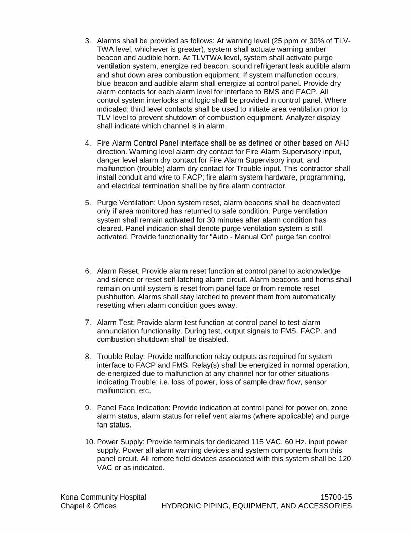
Kona Community Hospital 15700-15 Chapel & Offices HYDRONIC PIPING, EQUIPMENT, AND ACCESSORIES
3. Alarms shall be provided as follows: At warning level (25 ppm or 30% of TLV-TWA level, whichever is greater), system shall actuate warning amber beacon and audible horn. At TLVTWA level, system shall activate purge ventilation system, energize red beacon, sound refrigerant leak audible alarm and shut down area combustion equipment. If system malfunction occurs, blue beacon and audible alarm shall energize at control panel. Provide dry alarm contacts for each alarm level for interface to BMS and FACP. All control system interlocks and logic shall be provided in control panel. Where indicated; third level contacts shall be used to initiate area ventilation prior to TLV level to prevent shutdown of combustion equipment. Analyzer display shall indicate which channel is in alarm.
4. Fire Alarm Control Panel interface shall be as defined or other based on AHJ direction. Warning level alarm dry contact for Fire Alarm Supervisory input, danger level alarm dry contact for Fire Alarm Supervisory input, and malfunction (trouble) alarm dry contact for Trouble input. This contractor shall install conduit and wire to FACP; fire alarm system hardware, programming, and electrical termination shall be by fire alarm contractor.
5. Purge Ventilation: Upon system reset, alarm beacons shall be deactivated
only if area monitored has returned to safe condition. Purge ventilation system shall remain activated for 30 minutes after alarm condition has cleared. Panel indication shall denote purge ventilation system is still activated. Provide functionality for "Auto - Manual On” purge fan control
6. Alarm Reset. Provide alarm reset function at control panel to acknowledge
and silence or reset self-latching alarm circuit. Alarm beacons and horns shall remain on until system is reset from panel face or from remote reset pushbutton. Alarms shall stay latched to prevent them from automatically resetting when alarm condition goes away.
7. Alarm Test: Provide alarm test function at control panel to test alarm annunciation functionality. During test, output signals to FMS, FACP, and combustion shutdown shall be disabled.
8. Trouble Relay: Provide malfunction relay outputs as required for system
interface to FACP and FMS. Relay(s) shall be energized in normal operation, de-energized due to malfunction at any channel nor for other situations indicating Trouble; i.e. loss of power, loss of sample draw flow, sensor malfunction, etc.
9. Panel Face Indication: Provide indication at control panel for power on, zone
alarm status, alarm status for relief vent alarms (where applicable) and purge fan status.
10. Power Supply: Provide terminals for dedicated 115 VAC, 60 Hz. input power
supply. Power all alarm warning devices and system components from this panel circuit. All remote field devices associated with this system shall be 120 VAC or as indicated.

Kona Community Hospital 15700-16 Chapel & Offices HYDRONIC PIPING, EQUIPMENT, AND ACCESSORIES
L. FIELD DEVICES AND MISCELLANEOUS 1. Diffusion Refrigerant PPM Sensors: Provide NEMA 4X water and corrosion
resistant plastic enclosure, photoacoustic infrared sensor technology in wall mount enclosure. Sensor to be mounted on strut type steel channel at each chiller as noted above and in drawings. Sensor shall provide 50% step change response in 2.5 minutes and <4 minutes. Sensor shall be compound specific and calibrated for refrigerant as required per chiller manufacturer's requirement. Sensor full range shall be 0-1000 PPM with 4-20 mADC non-isolated, sourcing output and RS-485 Modbus RTU as standard. Sensor power shall be 24V DC/AC standard with 110/220 VAC optional. Accuracy shall be 20-100 ppm +/-5ppm and 100-1000 ppm +/-6%. Repeatability shall be +/-5 ppm full scale. Sensor low level detection shall be 20 ppm. Operating temperature range of 32 to 104 degrees F. Optional strip heater shall be available to extend temperature range. Humidity range shall be 0-95% RH noncondensing. Device shall be capable of sensing for R11, R12, R22, R123, or R134a. Analyzer shall have capability to be switched to monitor, at a future date, another refrigerant type by changing one part and recalibration. Sensor shall have UL31010-1 and Canadian CAN/CSAC22.2 Fire and Shock approvals. Sensor warranty shall be 24 months from date of installation or 30 months from date of shipment to jobsite. Electrochemical doped metal oxide sensing technology employing short-term life sensors, which deplete as a normal part of their operation or storage shelf life, shall not be acceptable. Sensor shall be mounted at 12” above finished floor. Provide SafeAir, Dräger Safety, O.I. Analytical or MSA.
2. Air Flow Switch; AFS: Provide general-purpose airflow switch to verify purge ventilation fan operation, differential type, as required for monitoring of area continuous and intermittent exhaust fans. Provide fan status indication at control panel.
3. Alarm Horns and Beacons: Provide stackable beacon assembly equal to Federal Signal / Edwards Triliptical / Allen Bradley; incandescent style, inside and outside of each area being monitored and at each entrance into monitored area. Provide Edwards horn assembly or equal, volume level shall be adjustable. Beacon and horns shall be general purpose, NEMA 4 for outdoors, Class 1, Div. 1 rated explosion proof as required; red, amber and blue. Outdoor strobes shall be visible in daylight conditions. All remote visual and audible devices shall be 120 VAC and powered from main control panel and emergency backup power source. Beacons and horns in occupied general-purpose areas exposed to general public shall be decorative, flush wall mount type, with High Intensity LED and decorative finish. Beacons shall be viewable throughout area being monitored.
4. Warning Signs and Tagging. Provide "Lamacoid" sign, red background with 1" high white letters at each remote visual and audible device. Anchor sign to wall adjacent to wall mounted devices, suspend with brass security chain adjacent to ceiling mounted devices.
5. Signs located inside and outside mechanical room shall be inscribed as
follows:
1) RED – DANGER LEVEL / R -_____

Kona Community Hospital 15700-17 Chapel & Offices HYDRONIC PIPING, EQUIPMENT, AND ACCESSORIES
2) AMBER – WARNING LEVEL / R -_____
3) BLUE – MALFUNCTION
6. Signs located at each entrance to mechanical room shall be inscribed as follows:
1) UPON REFRIGERANT ALARM / UNSAFE TO ENTER ROOM WITHOUT PROPER BREATHING APPARATUS.
7. Remote Reset: Provide minimum (1) remote reset pushbutton assembly at or near main entrance to mechanical room and additional where indicated on drawings to allow reset / silence from safe location. Remote pushbutton station shall be compatible with room decor. Signs at remote reset assembly shall denote "safe and unsafe" response action relating to local beacons and entrance to monitored area upon depressing remote reset pushbutton. Upon reset, if area monitored has been purged to safe level, beacons shall be deactivated and safe entry shall be permitted.
8. Provide Self Contained Breathing Apparatus in carrying case with “Lamicoid” tag above, yellow background with 3” high black letters inscribed “SELF CONTAINTED BREATHING APPARATUS”.
PART 3 - EXECUTION 3.01 INSTALLATION
A. Install piping and piping components to insure proper and efficient operation of
the equipment and controls and in accordance with manufacturer's printed instructions. Proper supports for the mounting of vibration isolators, stands, guides, anchors, clamps and brackets shall be provided. Piping connections to equipment shall be arranged so that removal of equipment or components of equipment can be accomplished with the least amount of disassembly or removal of the piping system. Piping connected to equipment with vibration isolators shall be provided with flexible connections which shall conform to vibration and sound isolation requirements for the system. Electric isolation shall be provided between dissimilar metals to reduce the rate of galvanic corrosion. 1. Water Piping: Air vents shall be provided at high points and drains at low
points in the chilled water system.
3.02 PIPING SYSTEMS
A. Cut to the measurements established at the site and work into place without springing or forcing. Install piping with line flexibility included to absorb the expansion and contraction due to temperature changes of the piping systems. Piping line flexibility shall be achieved by the use of pipe bends or loops or bellows type expansion joints. Where piping shall pass through the structure of the building the pipe joints shall not be concealed but shall be located where they are accessible for inspection.

Kona Community Hospital 15700-18 Chapel & Offices HYDRONIC PIPING, EQUIPMENT, AND ACCESSORIES
1. Flanged Joints: Faced true, square, tight and used where necessary for normal maintenance. Mate with valves and various equipment connections. Select gaskets, packing and thread compounds for suitability with the particular fluid with which they shall be in contact.
2. Reducing Fittings: Shall be used to connect changes of sizes in piping lines. Branch connections shall be made with tees except that factory made forged steel welding branch outlets or nozzles having integral reinforcements and conforming to ANSI B31.1 may be used if the nominal diameter of the piping system branch does not exceed one nominal pipe size less than the nominal size of the piping segment which contains the fitting.
3. Dielectric Unions or Flanges: Provide between ferrous and non ferrous
piping, equipment and fittings; except that bronze valves and fittings may be used without dielectric couplings for ferrous to ferrous or non ferrous connections. Flanges and unions shall conform to the requirements of ANSI B16.10 Standard.
4. Piping System Supports: Factory-fabricated by Elcen, Fee and Mason,
Grinnell, or Unistrut; no chains or straps permitted. Provide concrete inserts, beam clamps, channel framing hanger rods and accessories required for proper pipe support. Concrete inserts must be used at all pre-stressed planks.
5. Ramset or explosive type anchors are not permitted. Support steel and
copper pipe at maximum spacing of 6 feet for pipes 1-1/2 inches and smaller, 10 feet for pipes 2 inches through 4 inches and 15 feet for pipes larger than 4 inches. Support vertical piping with hanger at base of riser and with pipe clamp at each floor. On vertical chilled water risers, clamps shall be mounted 2" above finished slab with steel rod supports. At each support point on insulated piping, provide Pittsburgh Corning Foamglass insulation around pipe with 18-gage sheet metal jacket each two pipe diameters in length. Pipe hangers shall be steel clevis hanger with adjustable hanger rod; 3/8-inch for pipe 2 inches and smaller, 1/2-inch for pipe 2-1/2 inches through 3-1/2 inches and 5/8-inch for pipe 4 inches and larger. Groups of lines may be supported from steel channel with pipe clamp.
6. Pipe Guides: Shall be spider type, cylindrical type or hold down slide type utilizing factory bonded graphite, teflon or oil impregnated metal matched surfaces. Teflon or oil impregnated matched surfaces shall be protected and cleaned prior to start up.
7. Condensate Drain Piping Systems: Slope lines at 1/4-inch per foot unless otherwise directed. Provide a water seal with water column 1-inch greater than the total static pressure of the fan in inches of water. Terminate condensate drain over nearest plumbing drain when not otherwise indicated. See insulation specified hereinafter.
8. Flexible Connections: Install flexible pipe connectors or couplings on piping
connected to equipment. The material used and the configuration shall be suitable for pressure, temperature and circulating medium. The flexible section shall have flanged ends and shall be suitable for the service intended. The flexible section may be reinforced with metal retaining rings, with built-in

Kona Community Hospital 15700-19 Chapel & Offices HYDRONIC PIPING, EQUIPMENT, AND ACCESSORIES
braided wire reinforcement and restriction bolts or with wire braid cover suitable for the service intended.
3.03 CHILLED WATER PIPING
A. Fabrication and Assembly of Piping and Components: Welding shall conform to
ANSI B31.1 and as specified herein. Provide drain valves at low points of piping system and automatic air vent valves at high points where air pockets would occur. All piping shall follow the general arrangement shown, cut accurately to measurements established for the work by the Contractor and worked into place without springing or forcing, except where cold springing is indicated. Provide adequate clearance from walls and roofs to permit the welding of joints and re-roofing work; at least 6 inches for pipe sizes 4 inches and less, 10 inches for pipe sizes over 4 inches and in corners provide sufficient clearance to permit the welder to work between the pipe and one wall. Provision for expansion and contraction of pipe lines shall be made. Changes in size of water lines shall be made with reducing fittings. Protect materials and equipment from the weather. Use flanged joints only where necessary for normal maintenance and where required to match valves and equipment. Install joints so that flange faces bear uniformly on gaskets. All gaskets, packing and thread compounds shall be suitable for the service. Long radius ells shall be used wherever possible to reduce pressure drops.
B. Do not miter pipe to form elbows or notch straight runs to form full sized tees or any similar construction. All branch connections shall be made with welding tees except factory made forged welding branch outlets or nozzles having integral reinforcements conforming to ANSI B31.1 may be used, provided the nominal diameter of the branch is at least one pipe size less than the nominal diameter of the run. All piping shall be run essentially as indicated, avoid interference with other piping, conduit or equipment. Except where specifically shown otherwise, run vertical piping plumb and straight and parallel to walls. Trapping of lines shall not be permitted except as otherwise indicated. Provide sleeves of suitable size for all lines passing through building structure. Piping connected to equipment shall be installed to provide flexibility for thermal stresses and for vibration, and shall be adequately supported and anchored so that strain from weight and thermal movement of piping is not imposed on the equipment. Each section of pipe, fittings and valves shall be thoroughly cleaned and positively free of all foreign matter before erection. Prior to erection, each piece of pipe shall be held in an inclined position and thoroughly tapped to loose sand, mill scale and foreign matter. Before all final connections are made to apparatus, wash the interior of all piping thoroughly with water. Blow out piping with compressed air to remove rust chips, oil and debris. Plug or cap open ends of mains during all shutdown periods. Lines shall not be left open at any place where foreign matter might accidentally enter pipe. 1. Valves: Install at equipment to allow maintenance or isolation, and to
establish proper and sequential operation of the complete system.
2. Air Vent Valves: Provide at high points in water piping. Isolate valves and pipe to run off into the nearest floor drain.
3. Access Doors: Provide where required, whether shown on drawings or not,
for adequate access to controls and equipment. Where installed in fire rated
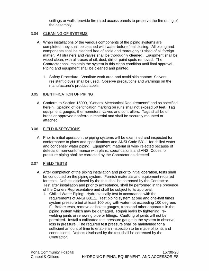
Kona Community Hospital 15700-20 Chapel & Offices HYDRONIC PIPING, EQUIPMENT, AND ACCESSORIES
ceilings or walls, provide fire rated access panels to preserve the fire rating of the assembly.
3.04 CLEANING OF SYSTEMS
A. When installations of the various components of the piping systems are
completed, they shall be cleaned with water before final closing. All piping and components shall be cleaned free of scale and thoroughly flushed of all foreign matter. All strainers and valves shall be thoroughly cleaned. Equipment shall be wiped clean, with all traces of oil, dust, dirt or paint spots removed. The Contractor shall maintain the system in this clean condition until final approval. Piping and equipment shall be cleaned and painted. 1. Safety Procedure: Ventilate work area and avoid skin contact. Solvent
resistant gloves shall be used. Observe precautions and warnings on the manufacturer's product labels.
3.05 IDENTIFICATION OF PIPING
A. Conform to Section 15000, "General Mechanical Requirements" and as specified herein. Spacing of identification marking on runs shall not exceed 50 feet. Tag equipment, gauges, thermometers, valves and controllers. Tags shall be of brass or approved nonferrous material and shall be securely mounted or attached.
3.06 FIELD INSPECTIONS
A. Prior to initial operation the piping systems will be examined and inspected for conformance to plans and specifications and ANSI Code B31.1 for chilled water and condenser water piping. Equipment, material or work rejected because of defects or non-conformance with plans, specifications and ANSI Codes for pressure piping shall be corrected by the Contractor as directed.
3.07 FIELD TESTS
A. After completion of the piping installation and prior to initial operation, tests shall be conducted on the piping system. Furnish materials and equipment required for tests. Defects disclosed by the test shall be corrected by the Contractor. Test after installation and prior to acceptance, shall be performed in the presence of the Owners Representative and shall be subject to its approval. 1. Chilled Water Piping: Hydrostatically test in accordance with the
requirements of ANSI B31.1. Test piping system at one and one-half times system pressure but at least 100 psig with water not exceeding 100 degrees F. Before tests, remove or isolate gauges, traps and other apparatus in the piping system which may be damaged. Repair leaks by tightening, re-welding joints or renewing pipe or fittings. Caulking of joints will not be permitted. Install a calibrated test pressure gauge in the system to observe loss in pressure. The required test pressure shall be maintained for a sufficient amount of time to enable an inspection to be made of joints and connections. Defects disclosed by the test shall be corrected by the Contractor.

Kona Community Hospital 15700-21 Chapel & Offices HYDRONIC PIPING, EQUIPMENT, AND ACCESSORIES
3.08 START-UP AND OPERATIONAL TESTS
A. The chilled water systems shall be started up and initially operated. During this time, the various strainers shall be periodically cleaned until no further accumulation of foreign material occurs. Adjust safety and automatic control instruments as necessary to place them in required operation and sequence.
END OF SECTION 15700

Kona Community Hospital 15800-1 Chapel & Offices AIR CONDITIONING AND VENTILATION
SECTION 15800 - AIR CONDITIONING AND VENTILATION PART 1 - GENERAL 1.01 RELATED DOCUMENTS
A. Drawings and general provisions of the Contract, including General and
Supplementary Conditions and Division 01 Specification Sections, apply to this Section.
B. Section 15000, "General Mechanical Requirements", applies to this section with the additions and modifications specified herein.
1.02 WORK SPECIFIED IN THIS SECTION
A. Provide complete and operating air conditioning and ventilating system. "Provide"
shall mean "furnish and install" when used herein. 1. Electrical: Provide all temperature, pressure, flow, and indicating controls for
this work. Mount control devices and provide control wiring and conduit. Furnish motor starters for equipment under this section.
1.03 RELATED WORK SPECIFIED IN OTHER SECTIONS
A. Electrical: Mounting of starters and providing of fused or non-fused disconnect switches, circuit protection, and power wiring conduit are under DIVISION 16 ELECTRICAL.
B. Excavation, trenching, and backfilling are under DIVISION 2 SITE-WORK.
C. Concrete bases and supports are under DIVISION 3 CONCRETE.
D. Painting of this work is under DIVISION 9 FINISHES, unless otherwise indicated hereinafter.
1.04 QUALITY ASSURANCE
A. Comply with all the requirements of the County of Hawaii and State of Hawaii.
B. Obtain and pay for all fees, permits, licenses, assessments, and inspections
required for this work.
C. Unless specified under the General Provisions of the approved Construction contract, substitutions of another manufacturer's product for equipment specified hereinafter and for items with "or equal" after the brand name requires written permission by the WHFD AND/OR PROJECT MANAGER substitution deadline. No substitution will be considered after the bid opening.
D. Comply with the recommendations and requirements of the Codes and
Standards listed hereinafter in addition to detailed requirements of this specification.

Kona Community Hospital 15800-2 Chapel & Offices AIR CONDITIONING AND VENTILATION
1. American Society of Heating, Refrigerating, and Air Conditioning Engineers (ASHRAE): a. Handbook, Applications (Current Edition)
b. Handbook, Systems and Equipment – (Current Edition)
c. Safety Standard for Refrigeration Systems – (Current Edition)
d. 62.1 Standards for Ventilation and Indoor Air Quality
2. National Fire Protection Association (NFPA) Standards (Current Editions):
a. Air Conditioning and Ventilating Systems
b. Standard for Ventilation Control and Fire Protection of Commercial
Cooking Operations
c. National Electric Code
3. Air Conditioning, Heating, and Refrigeration Institute (AHRI) Standards (Current Editions): a. Forced-Circulation Air Cooling and Heating Coils.
b. Sound Rating of Ducted Air Moving and Conditioning Equipment
4. Air Moving and Control Association (AMCA) Standards (Current Editions):
a. Laboratory Methods of Testing Fans for Certified Aerodynamic
Performance Rating
b. Reverberant Room Method for Sound Testing of Fans
5. American Society of Mechanical Engineers (ASME) (Current Edition): a. Boiler and Pressure Vessel Code
6. Sheet Metal and Air Conditioning Contractors National Association
(SMACNA): a. Duct Construction Standards – Metal and Flexible, 1995.
7. Hawai’i State Department of Health (Current Editions):
a. Title 11, Chapter 11 – Sanitation
b. Title 11, Chapter 39 – Air Conditioning and Ventilation
8. International Building Code, with County of Hawai’i Amendments – 2006
9. International Energy Conservation Code (IECC), with County of Hawai’i
Amendments – 2015
Kona Community Hospital 15800-3 Chapel & Offices AIR CONDITIONING AND VENTILATION
1.05 SUBMITTALS Submit under provisions of 01300- SUBMITTALS. Submit six (6) copies of each submittal required hereinafter.
A. Equipment Submittals: Before beginning work, submit for review manufacturer certified literature showing ratings and dimensions of equipment and of a list indicating all materials and items that are of a different manufacturer or model than those specified. Include equipment wiring diagrams.
B. Shop Drawings: After review of equipment, submit for review and approval dimensioned installation shop drawings to scale showing details where space requirement presents problems; proposed departures from the Contract Documents due to field conditions, requirements for concrete work, access panels, inserts in slabs, and openings in structure.
C. As-Built Drawings: Record changes from the contract drawings of all concealed
piping, duct work and equipment. Indicate location of isolating valves, dampers, and items requiring maintenance or inspection. Submit as-built drawings in accordance with Section 01300-Submittals.
D. Operation and Maintenance Manuals: Furnish operating and maintenance
manuals on all equipment and the system as a whole and in accordance with Section 15000 - General Mechanical Requirements.
E. Certificates: The Hospital will have the right to require a written certificate, dated
and signed by a responsible employee of the Contractor, evidencing the performance of any portion of the work, or any testing; as a condition precedent to the acceptance of any work or the result of any test. Whenever a regulatory agency performs inspections or tests of any portion of the work, a certificate shall be furnished by the Contractor that the inspection or test was satisfactorily passed.
F. Commissioning Submittals:
1. Commissioning Plan
2. Test Checklists and Report Forms.
3. Certificates of Readiness
4. Test and Inspection Reports
5. Corrective Action Documents
6. Commissioning Report
7. System Manual
1.06 PRODUCT DELIVERY, STORAGE, AND HANDLING
A. Furnish new equipment, material, and accessories bearing the manufacturer's
identification. Coordinate deliveries to avoid interferences or construction delays.

Kona Community Hospital 15800-4 Chapel & Offices AIR CONDITIONING AND VENTILATION
Protect products during delivery, storage, installation and the remainder of the construction period after installation.
1.07 GUARANTEE
A. All work in this section shall be guaranteed for a period of one year from the date of acceptance of the work as a whole by the County and as indicated in Section 15000. Correction of undue noise or vibration is included in the guarantee.
B. Normal maintenance requirements are not included in this guarantee. Should any equipment or material fail within this period, the Contractor shall be responsible for any damage to any part of the premises caused by leaks in piping or equipment for a period of one year after final acceptance of the work as a whole by the Hospital.
PART 2 - PRODUCTS 2.01 GENERAL
A. Asbestos Prohibition: No asbestos containing materials or equipment shall be
used under this section. The Contractor shall ensure that all materials and equipment incorporated in the project as asbestos-free.
2.02 SALT CORROSION PROTECTION
A. See Section 15000 – General Mechanical Requirements for details.
2.03 EQUIPMENT
A. Capacities and characteristics of equipment are indicated on the drawings. See electrical drawings for all voltage and phase requirements of all equipment furnished under this work. Provide combination magnetic across the line starter and circuit breaker for each motor of mechanical equipment unless the equipment is factory wired to a single power connection or unless otherwise indicated herein-after. Provide NEMA 3R weatherproof starters with fiberglass enclosure for the outdoor installation. Provide vibration isolators as indicated hereinafter.
EQUIPMENT ISOLATOR
DESCRIPTION MINIMUM STATIC
DEFLECTION
Air Handling Units Spring Isolators
Vertically Restrained 1.00”
Air Cooled Condensing Units
Vertically Restrained Spring Isolators 1.00”
Exhaust Fan Hangers
Vertical Spring Isolator 1.00”

Kona Community Hospital 15800-5 Chapel & Offices AIR CONDITIONING AND VENTILATION
B. *Isolator mounting location shall be in accordance with manufac¬turer's dimensioned drawings. Isolators shall be sized to provide specified static deflection from manufacturer's published loading information at each mounting point, based on operating weight.
2.04 AIR HANDLING UNIT
A. General: Unit performance shall be rated in accordance with AHRI (Air-Conditioning, Heating and Refrigeration Institute) Standard 430 for Central Station Air-Handling Units and subject to verification of rating accuracy by AHRI-sponsored, third party testing.
B. Coils shall be certified in accordance with AHRI Standard 410, latest edition.
C. Direct expansion coils shall be designed and tested in accordance with ANSI/ASHRAE (American National Standard Institute/American Society of Heating, Refrigerating and Air-Conditioning Engineers) 15 Safety Code for Mechanical Refrigeration.
D. Insulation and insulation adhesive shall comply with NFPA (National Fire
Protection Association) 90A requirements for flame spread and smoke generation.
E. The management system governing the manufacture of this product is ISO
9001:2008 certified.
F. Unit shall be constructed in accordance with ETL and CSA (Canadian Standards Association) standards and shall carry the ETL and CSA labels.
1. Delivery Storage and Handling:
a. Unit shall be stored and handled in accordance with the unit
manufacturer’s instructions. Unit shall be a factory-assembled, single-piece central station air handler. Unit may consist of a fan and coil section with factory-installed chilled water or direct expansion coil, preheat or reheat coil, heating coil section, filter section, mixing box or combination filter/mixing box, or access section as indicated on the equipment schedules. Unit base rail shall be 14 gage galvanized steel.
b. Unit Cabinet:
1) Unit panels shall be constructed of 20 gage galvanized steel. Casing panels shall be removable for easy access to the unit. All panels shall be gasketed to ensure a tight seal.
2) Optional double wall construction shall be available with inner panels constructed of 20 gage steel.
3) Hinged access doors shall be double wall with 1.5 lb dual-density
fiberglass between galvanized steel panels.

Kona Community Hospital 15800-6 Chapel & Offices AIR CONDITIONING AND VENTILATION
4) Insulation for casing panels on unit shall be 1-in. minimum thickness dual-density fiberglass insulation with a nominal density of not less than 1.5 lb per cubic foot.
5) Insulation shall be secured to casing with waterproof adhesive.
6) Condensate drain pans shall be sloped to prevent standing water and
constructed of stainless steel; they shall have double wall construction with threaded drain connection.
c. Fan Section:
1) Fan sections shall be constructed of galvanized steel and shall have a
formed channel base for integral mounting of fan, motor, and casing panels. Fan scroll, wheel, shaft, and bearings are to be rigidly secured to the base unit.
2) Each unit shall have a single fan wheel and scroll. Fans shall be double width, double inlet type, with forward-curved blades. Wheels shall be bonderized steel with baked enamel, or galvanized steel.
3) Fan wheels shall be keyed to the shaft and shall be designed for
continuous operation at the maximum rated fan speed and motor horsepower. Fan wheels and shafts shall be selected to operate at least 25% below the first critical speed, and shall be statically and dynamically balanced as an assembly.
4) Fan shafts shall be solid steel, turned, ground and polished.
5) Fan bearings shall be self-aligning, pillow-block regreasable ball type
selected for an average life of 200,000 hours at design operation conditions, per ANSI Code B3.15.
6) Fan motor shall be mounted within the fan section casing on slide rails
having 2 adjusting screws. Motor shall be NEMA (National Electrical Manufacturing Association) Design B with sizes and electrical characteristics as shown on the equipment schedule.
7) Fan drive shall be designed for a 1.5 service factor and shall be
factory mounted and aligned. Belt drive shall be variable or fixed-pitch type.
d. Coil Sections:
1) All coils shall have mill galvanized casings. Coils shall be factory leak
tested at 450 psig air pressure. Chilled water coils shall have aluminum plate fins with belled collars bonded to 1/2-in. minimum OD copper tubes by mechanical expansion. Coils shall have galvanized steel casings and copper headers with threaded steel pipe connections. Working pressure shall be 300 psig at 200 F. Coils shall be drainable and have non-trapping circuits. No turbulence- promoting devices will be permitted inside the tubes. Headers shall have drain and vent connections.

Kona Community Hospital 15800-7 Chapel & Offices AIR CONDITIONING AND VENTILATION
e. Filter Sections: 1) Each filter section shall be designed and constructed to house the
specific type of filter specified on the equipment schedule.
2) Flat filter sections shall accept filters of standard sizes. Sections shall include side access slide rails and hinged door access. Flat filter section shall be arranged with minimum depth in direction of airflow.
3) Angle filter section shall accept 2-in. filters arranged in horizontal V formation. Double-walled hinged doors shall be provided.
f. Access Sections: 1) Access sections shall be installed where indicated on the drawings
and shall be as specified on the equipment schedule.
2) Access sections shall have double-walled hinged doors.
g. Special Features: The following unit options shall be available. 1) Coil Section:
a) Chilled water coil with copper plate fins or e-coated fins and
stainless steel casing.
b) Hot water (U-bend) coil with copper plate fins or e-coated fins and stainless steel casing.
2.05 VARIABLE FREQUENCY DRIVE
A. Variable Frequency Drives Acceptable Manufactuers
1. Franklin Control Systems
B. General Design
a. All VFD’s must be solid state, utilizing PWM control with energy
optimizing control algorithms for lower operating temperature.
b. VFD’s shall be current rated, with each model capable of operating on voltages of 200~480 VAC +/- 10%, 3 Phase.
c. VFD’s shall be suitable for use on a circuit capable of delivering not more
than 100,000 rms symmetrical amperes, 480 V per UL 61800-5-2 guidelines, without the use of external fused protection. Manufacturer’s short circuit testing shall be performed at full rated capacity of 100,000 Amps.
d. The VFD must be minimum UL Type 1 for indoor applications, and UL
Type 3R for outdoor applications.

Kona Community Hospital 15800-8 Chapel & Offices AIR CONDITIONING AND VENTILATION
e. VFD must utilize R3Filtering or equivalent to reduce harmonics on the line side of the VFD. Harmonic mitigation shall reduce THDi to 35% or less without the use of external reactors or filters.
f. With cover removed, VFD shall have a minimum IP20 (finger safe) rating,
with high voltage terminals protected from contact with the installer/operator.
g. Circuit boards shall be conformal coated to protect against dust and
corrosion.
h. VFD cooling fans shall be easily replaceable without the use of special tools, or removal of the VFD from the wall. Cooling fans shall also be replaceable without removal of circuit boards, field wiring, and factory wiring. Cooling fans shall only run when needed based on the internal temperature of the VFD.
i. Programming of the VFD shall be HVAC specific, with guides that walk
the operator through the start-up procedure with access to troubleshooting info through the display.
j. All VFD shall include two independent analog inputs as standard,
programmable for 0 –10VDC or 4-20mA. Both analog inputs shall be utilized as speed references, or as PID inputs. The analog inputs shall be programmed as an individual reference at a time, or as a combined reference together.
k. There shall be a minimum of (2) configurable digital inputs, and (2)
configurable voltage inputs. Digital inputs shall be configurable as normally open or normally closed, and be rated up to 8mA at 24 VDC. Voltage inputs shall be capable of interfacing with 12-240V, 8mA max.
l. There shall be a minimum of (1) relay outputs rated up to 1 amp at 240
VAC normally open contact. Relay shall be configurable for Fault, Run and status. 240V 1A maximum rating.
2. AC Line Reactors And DC Filters
a. Provide ac line reactor to reduce harmonics.
b. Provide dc filters when cable lengths are greater than 20'.
3. Keypad
a. The VFD display shall be a backlit, full color OLED display. The VFD shall
display information in complete English words (alpha-numeric codes are not acceptable unless accompanied by complete English descriptions on the display). Faults shall also be written in complete English words.
b. The VFD shall have dedicated HOA buttons, and LED indicator lights to clearly designate HOA position.

Kona Community Hospital 15800-9 Chapel & Offices AIR CONDITIONING AND VENTILATION
c. The VFD display shall clearly indicate the operational state of the VFD, in addition to running values on the home (default) screen. This shall include at minimum:
1) Run status
2) Fault status
3) Forward/Reverse
4) Speed in Hz or RPM
5) Running current
6) Average RMS voltage
7) Run source (Terminal, Keypad, HOA, Communications)
8) Min/Max Speed
9) PID set point, and min/max units when running in PID mode
d. VFD keypad shall be capable of passcode protection.
4. Elecrical Ratings
a. Voltage: Input 200~480 VAC +/- 10%, 3 phase, 48-63Hz
b. Output Frequency: 0-400 Hz
c. Power factor: ≥ .99
d. Efficiency: ≥98%, full load
e. Overload capacity: 110% for 60s @ 40°C, 83% for 30s @ 50°C
f. Carrier Frequency: 2kHz - 10kHz, 0.1kHz resolution, Default 2.5kHz
g. Harmonics: R3Filtering ≤ 35% THDi, without external reactors or filters
h. EMI/RFI: VFD’s shall include EMI/RFI filters acceptable for the 1st
Environment (Category C2), compliant to EN 61800-3 Radiated and Conducted Emissions
5. Environmental Ratings
a. Temperature 1) Operating Temperature: -10 to 40°C 2) Storage Temperature: -20 to 65°C

Kona Community Hospital 15800-10 Chapel & Offices AIR CONDITIONING AND VENTILATION
b. Altitude 1) Max 1000m above sea level
2) De-rate 1% per 100m from 1000-2000m and 2% per 100m from 2000-
3000m
c. Humidity: 95% relative humidity, non-condensing
d. Enclosures
1) UL Type 1 minimum for indoor mounting locations
2) UL Type 3R minimum for outdoor mounting locations
3) VFD shall be IP20 (finger safe) with cover removed
6. Standard Features a. VFD shall provide start-up report in PDF format that details all running
values, and settings. All settings that have been changed from factory default shall be highlighted in the report such that changes are easily distinguishable.
b. The VFD shall incorporate a real-time clock with battery back-up allowing faults and setting changes to be logged with real time and date. The battery shall replaceable without removal of factory wiring or circuit boards. Battery shall have a minimum life span of 10 years under normal operating conditions.
c. All programming shall be HVAC specific, with common HVAC
applications available to expedite the start-up process by automatically adjusting parameters according to the application selected.
d. All VFD must have a motor preheat function to prevent moisture
accumulation in an idle motor.
e. All VFD must be capable of maintaining a set point via microprocessor based PID control on closed loop systems utilizing external 4-10mA, or 0-10V analog transmitters. VFD’s must be capable of providing auxiliary power up to 0.5 amp at 24 VDC for external transmitters. PID set points shall be adjustable via the VFD keypad, communication protocols. Digital inputs shall be programmable to switch between pre-configured user defined set points.
f. PID: Control action, proportional plus integral derivative.
g. All VFD display units shall be selectable, and shall automatically adjust
based on Applications selected at start up. VFD shall be capable of displaying PSI, Degrees F/C, inWC, Bar, mBar, Pa, kPa.
h. VFD’s shall have sleep and wake functions to save energy when set point
is met in PID mode, and there is no additional demand on the system.

Kona Community Hospital 15800-11 Chapel & Offices AIR CONDITIONING AND VENTILATION
i. Sleep boost functionality shall be used on PID controlled pressurized
water systems to ensure the drive doesn’t start and stop too frequently when at or near the desired pressure set point .
j. The VFD shall provide frequency setting resolution of 0.01 Hz when its
Digital Reference is utilized below 100 Hz and 0.1 Hz over 100 Hz. The VFD shall provide frequency setting resolution of 0.03 Hz / 60 Hz when Analog Reference is utilized.
k. The VFD shall have the ability to automatically restart after an over-
current, over-voltage, under-voltage, or loss of input signal protective trip. The number of restart attempts, trial time, and time between reset attempts shall be programmable.
l. The VFD shall be capable of both Automatic and Manual Torque Boost
function to overcome sudden fluctuation of the load.
m. The VFD shall be capable of starting into a rotating load (forward or reverse) and accelerate or decelerate to set-point without safety tripping or component damage (flying start).
n. All VFD shall have 1 analog output (0-10VDC) which can be programmed
to function as one of the following: Output Frequency, Output Current, and DC Bus Voltage. Default is set to Output Frequency.
o. If the input reference (4-20mA or 0-10V) is lost, the VFD shall give the
user the option of either (1) stopping and automatically reset once a signal restored (2) displaying a fault, (3) holding the VFD speed based on the last good reference received 1 second prior to losing the signal. The drive shall be programmable to signal this condition via a keypad warning, relay output and/or over the serial communication bus.
p. The customer terminal strip shall be isolated from the line and ground.
q. The VFD shall have dedicated damper control terminals capable of
providing up to 1 amp, 24VDC to open a damper actuator, and ensure end switch closure with normally open dry contact. To ensure proper damper functionality a damper time delay shall be programmable. The VFD shall fault in the event that the damper fails to make contact with the end switch within the user defined time delay. Use of external relays and CPT’s is prohibited unless damper loads exceed 1 Amp max.
r. The Maximum current limit shall be fixed at 150% (minimum,
instantaneous) of the VFD normal duty current rating. s. The VFD shall be capable of 3 preset speeds that are activated via Digital
Input Terminals.
t. The VFD shall provide from 1 to 6000 seconds of Acceleration and Deceleration time setting parameters.

Kona Community Hospital 15800-12 Chapel & Offices AIR CONDITIONING AND VENTILATION
u. The VFD shall be optimized for various levels of carrier frequency programmable from 2 to 10 kHz to reduce motor noise and to provide high system efficiency.
v. VFD’s shall have a minimum of 3 critical lockout skip frequency ranges.
Low and high frequency settings shall programmable for each lockout skip frequency range.
w. VFD’s shall be capable of recording minimum of 100 faults and 25 setting
changes with true time and date stamping. Faults and settings shall be downloadable in PDF format.
x. VFD’s shall allow settings to be stored as configuration templates in
manufacturer provided mobile application. Configuration templates shall be capable of being uploaded into un-configured VFD’s to expedite the start-up process.
y. The VFD shall have the following protection features. In the case of a
protective trip, the drive shall stop and announce the fault condition. Options shall be available for faults to auto reset and retry with adjustable time delay. When VFD’s are in fault conditions, display shall clearly indicate the name of the fault in plain English. Fault codes are not acceptable. The display shall also clearly indicate if the VFD is awaiting an automatic restart by counting down time until next restart.
1) Motor overload
2) Motor overcurrent
3) VFD overcurrent
4) VFD short circuit
5) Overvoltage
6) Undervoltage
7) Input phase open
8) Output phase open
9) No motor
10) Ground Fault
z. The VFD shall have the following faults to ensue desired operation
1) BMS communication loss
2) Speed signal loss
3) Transducer failure

Kona Community Hospital 15800-13 Chapel & Offices AIR CONDITIONING AND VENTILATION
aa. All VFD shall be capable of configuring digital inputs or voltage inputs for dedicated shutdown, or fireman’s override functionality under the following premise. 1) Shutdown
a) When configured for shutdown, the digital input or voltage input
terminal shall override all other commands and stop the VFD in any mode. This condition shall be stored in the VFD fault log.
2) Fireman’s Override a) When configured for Fireman’s Override, the digital input or
voltage input terminal shall override all other commands and run the VFD at user defined preset speed until the terminal is deactivated. During a Fireman’s override condition, all non-critical faults shall be ignored, and VFD shall “run to destruct” if configured terminal is not deactivated. Once the override signal is removed the VFD shall automatically return to normal operation.
7. Communications a. All VFD’s must have RS-485 ports as standard. The following BAS
communication protocols shall be native to the VFD, without the need for option boards: 1) BACnet MS/TP
2) Modbus TCP
b. Serial communications shall include the following capabilities; start/stop
and speed control, monitoring of all running values, fault and alarm indication, fault detail, power consumption data, I/O configuration and status, VFD firmware and hardware identification, configuration of startup parameters, and configuration of protective functions.
c. VFD’s must be accompanied by wireless mobile application to assist with start-up, troubleshooting, uploading/downloading of parameters, firmware updates, reporting, and fault logging. Application to be provided at no additional charge.
d. Minimum 128-bit AES encryption shall be used for any wireless communication.
8. Bypass
a. VFD Bypass shall be integral to the VFD, and provide the same level of
protection as the base VFD unit when in Bypass mode. Thermal overload protection is not acceptable.
b. VFD Bypass shall not have a separate set of customer control terminals.
A single set of control terminals shall be provided, with electrical isolation
Kona Community Hospital 15800-14 Chapel & Offices AIR CONDITIONING AND VENTILATION
and control logic isolation to ensure bypass operation is unaffected in the event of VFD failure.
c. VFD shall have the ability to automatically switch to bypass mode in the
event of a VFD fault. For protective functions with automatic restart enabled, the VFD shall attempt to restart in VFD mode prior to switching to bypass. Auto-bypass functionality shall be user selectable.
d. Bypass shall maintain BACnet or Modbus communication when in bypass
mode, and in the event of VFD failure.
e. Bypass shall have the following SmartStart protection features to ensure smooth across the line operation when in bypass mode:
1) Stall prevention 2) Locked rotor
3) Max time to start
f. Bypass shall be capable of monitoring current. Thermal overload
protection is not acceptable. g. VFD bypass shall maintain control by monitoring the VFD’s analog input.
This will control the bypass in an on or off state to maintain desired setpoint/process output.
2.06 VARIABLE AIR VOLUME TERMINAL UNITS
A. General: Factory-assembled, externally powered, variable air volume control
terminal. Unit shall be complete with a damper assembly, flow sensor, externally mounted volume controller, collars for duct connection and all required features. Control box shall be clearly marked with an identification label that lists such information as nominal cfm, maximum and minimum factory-set airflow limits, coil type and coil hand, where applicable.
B. Unit Cabinet: 1. Constructed of 22-gage galvanized steel with round, rectangular or flat oval
inlet collar and rectangular discharge with slip and drive connection.
2. Insulated with 1 inch thick, 1.5-lb equivalent density mat-faced insulation. The insulation shall meet UL 181 and NFPA 90A. It shall be enclosed between the unit’s zinc coated sheet metal casing and a non-perforated internal zinc-coated sheet metal cover, which extends over the fiberglass insulation, as well as the cut edges of the material.
C. Damper Assembly: The damper assembly shall be composed of multiple 16-
gage damper blades located in a 16-gage damper frame, utilizing steel damper linkages and mounted on nylon self lubricating blade bearings. Dampers shall have an open cell foam damper seal affixed to the blade, providing a maximum of 2% of the maximum rated capacity with dampers closed with an inlet pressure of 3 in. wg. Damper assembly will consist of either 4 or 6 blades with a 90
Kona Community Hospital 15800-15 Chapel & Offices AIR CONDITIONING AND VENTILATION
degree travel, and shall provide uniform air delivery over the entire face of the unit at all flows.
D. Controls: 1. Units shall have electronic controls capable of maintaining required airflow
set-points +/- 5% of the unit’s capacity at any inlet pressure up to 6 in. wg. The controller shall be capable of resetting between factory or field-set maximum and minimum (>350 fpm inlet duct velocity) set points to satisfy the room thermostat demand.
2. The unit shall be equipped with a double ended amplified linear averaging
flow probe located horizontally across the inlet. The probe shall have capped ports at the end opposite to the controller connection for flow verification in the field against provided flow/pressure charts. The sensor will provide a differential pressure signal amplified to equal 3 times the velocity pressure with an accuracy of +/- 10% throughout the range of 350 to 2600 fpm inlet duct velocity.
E. Special Features:
1. Hot Water Heating Coil:
a. Coil shall be mounted in a minimum 20-ga. galvanized steel casing with slip and drive discharge connections and factory mounted on the base unit as shown on the equipment drawings.
b. Coils shall have: 1) Aluminum fins (10 ft per in.) bonded to the copper tubes by
mechanical expansion. 2) Number of coil rows and circuits shall be selected to provide
performance as required by the plans. 3) Up to 4 rows as shown on equipment drawings or designed on the
equipment schedule. Right or left-hand fittings with sweat connection sizes as indicated on equipment drawings.
2. Sound Attenuator: The sound attenuator section shall consist of a continuous
extension of the standard zinc coated steel casing. 3. Control Transformers:
a. Electric heat units shall include a factory supplied, mounted and wired control transformer inside the electric heat enclosure for electronic control applications.
b. Non-electric heat units, with electronic controls, shall be provided with a
factory supplied, mounted, and wired control transformer, mounted inside the control enclosure.
4. Hanger Brackets: Shall be field-installed for use with ceiling installation of the
terminal unit.

Kona Community Hospital 15800-16 Chapel & Offices AIR CONDITIONING AND VENTILATION
5. Non-Fused Disconnect: Non-fused switch shall provide unit power shutoff.
Shall be accessible from outside the unit and shall provide power off lockout capability.
2.07 UV LAMPS
A. UV lamps shall be Totaline Germicidal Purification UV Dual Lamps. 1. Non ozonating lamp.
2. Dual 36 watt-254 nanometer UVC lamps.
3. Anodized aluminum parabolic reflectors.
4. Lamps shall have a minimum 9000 Life-Hours.
5. 24/120 Volt operation
6. Magnetic mounting base
7. Extended range ballast
8. Delta plate option
2.08 DRAIN PAN WATER SWITCH
A. Provide electronic water switch in secondary drain pans where indicated on
drawings. Switch shall sense the presence of water and shut down associated equipment upon moisture detection. Switch shall be configured as fail-safe, and be rated for capacity of 250v 5 amps (max). Switch shall be provided by the mechanical contractor and wired by the electrical contractor. Wire per manufacturer’s instructions, test switch after performance verification of air conditioning system to ensure proper operation.
2.09 VALVES
A. Safety Relief Valves: Provide bodies of forged brass with nonferrous, corrosion resistant internal working parts or high strength, cast iron bodies conforming to ASTM A126, Grade B with corrosion resistant internal working parts. Brass Bodies shall have brazing connections. Cast iron body valves shall have flanged connections. Set valves in accordance with ASHRAE 15.
B. Control Valves:
1. 2-way characterized control valve with stainless steel ball and stem.
2. Spring return control damper actuators shall be direct coupled type which require no crank arm and linkage and be capable of direct mounting to a jackshaft up to a 1.05” diameter. The actuator must provide proportional damper control in response to a 2 to 10 VDC or, with the addition of a 500Ω resistor, a 4 to 20 mA control input from an electronic controller or positioner. The actuators must be designed so that they may be used for either

Kona Community Hospital 15800-17 Chapel & Offices AIR CONDITIONING AND VENTILATION
clockwise or counterclockwise fail-safe operation. Actuators shall use a brushless DC motor controlled by a microprocessor and be protected from overload at all angles of rotation. Run time shall be constant, and independent of torque. A 2 to 10 VDC feedback signal shall be provided for position feedback. Actuators shall be cULus Approved and have a 5 year warranty, and be manufactured under ISO 9001 International Quality Control Standards. Actuators shall be as manufactured by Belimo.
2.10 CONDENSATE DRAIN PIPING
A. Condensate drain piping shall be Schedule 80 PVC pipe and drainage pattern
fittings with solvent welded joints. Provide seal trap at connection to unit and size according to system static pressure. Provide cleanouts at every change in direction of the condensate piping. All interior condensate drain piping shall be insulated per Section 15250 – Insulation of Mechanical System.
2.11 DUCT WORK AND ASSOCIATED SHEET METAL WORK
A. All low velocity ducts shall be galvanized steel with gages and construction in accordance with SMACNA Duct Construction Standards – 2005. Use of duct board will not be approved.
B. All high velocity ducts shall be galvanized steel with gages and construction in accordance with SMACNA Duct Construction Standards – 2005. Use of duct board will not be approved.
C. Splitter damper shall be adjustable with locking quadrant.
D. Flexible connections shall be U/L approved neoprene-coated glass fabric cloth.
E. Flexible duct shall be U/L labeled with 1 inch thick fiberglass insulation and
externally insulated.
F. All sheet metal duct work shall be sealed at all joints and made air tight by applying an approved sealant compound around all joints per the manufacturer’s recommendations.
2.12 AIR DISTRIBUTION DEVICES
A. All aluminum construction for face plates, frames and grilles:
1. Ceiling Diffusers:
a. All aluminum construction, square surface mount, off-white baked enamel
finish. Provide lay-in diffuser where indicated on plan. Titus TDC-AA or approved equal. Provide lay-in register where indicated on plan.
b. All aluminum construction, square surface mount, off-white baked enamel finish. Provide lay-in diffuser where indicated on plan. Titus 300FS or approved equal. Provide lay-in register where indicated on plan.
2. Return Air Registers:

Kona Community Hospital 15800-18 Chapel & Offices AIR CONDITIONING AND VENTILATION
a. All aluminum construction, square surface-mounted with opposed-blade volume damper, off-white baked enamel finish. Provide lay-in register where indicated on plan. Titus 350FL-AA or approved equal.
3. Volume Dampers: All aluminum construction with locking device. Contractor shall provide access doors at all volume damper locations to provide for adjustments during balancing of the air conditioning system. Where installed in fire rated assemblies, access doors shall be rated to preserve the fire rating of the assembly. Ruskins or equal.
4. Exhaust Registers/Wall Registers: All aluminum construction, surface-mounted with opposed-blade volume damper, off-white baked enamel finish. Titus 350 or approved equal.
5. Backdraft Dampers: All aluminum construction, counter weighted and field
adjusted to provide positive seal against reverse flow or air conditioned air. Ruskins or approved equal.
B. Fire Dampers: Shall be UL555 rated, dynamic type, and constructed of
galvanized steel. Fire dampers shall have 1-1/2 hour rating for fire rated assemblies of less than 3 hours and 3 hour rating for fire rated assemblies of 3 hours or more. Provide air tight duct access panels as required for routine maintenance of the fire dampers. Temperature rating of the fire damper shall be 165°F.
C. Fire Smoke Dampers: Combination fire smoke dampers meeting or exceeding the following specifications shall be furnished and installed at locations shown on plans or as described in schedules. Combination fire smoke dampers shall be produced in an ISO 9001 certified factory and shall be warranted to be free from defects in material and workmanship for a period of 5 years after date of shipment. Dampers shall meet the requirements of NFPA 80, 90A, 92A, 92B, 101 and 105 and shall have a fire rating of 1.5 hours in accordance with the latest edition of UL555 and shall be classified as Leakage Class II Smoke Dampers in accordance with the latest version of UL555S. 1. Damper frame (when size permits) shall be minimum 16 gauge galvanized
steel formed into a structural hat channel superior to 13 gauge channel frame. Damper blades shall be single piece airfoil shaped with 14 gauge equivalent strength and shall run vertically within the frame. Blade edge seals shall be inflatable silicone mechanically locked into blade edge. Jamb seals shall be stainless steel compression type. Bearings shall be stainless steel, permanently lubricated sleeve type turning in an extruded hole in the frame for maximum life.
2. Combination fire smoke dampers and their actuators shall be qualified in accordance with UL555S to an elevated temperature of 250°F (121°C) or 350°F (177°C) depending upon the actuator. Appropriate electric or pneumatic actuators (specifier select one) shall be installed by the damper manufacturer at time of damper fabrication. Electric actuators, factory installed on dampers, shall have been tested for prolonged periods of holding (minimum 1 year) with no evidence of reduced spring return performance. Each damper shall be rated for leakage and airflow in either direction through the damper. Ruskin FSD or approved equal.

Kona Community Hospital 15800-19 Chapel & Offices AIR CONDITIONING AND VENTILATION
2.13 MOTORIZED DAMPERS:
A. All aluminum construction with opposed blades. Actuator shall be powered by 24 Vdc input with modulating control signal, 0-10 Vdc or 4-20 mAdc. Actuator shall be externally mounted. Return air dampers shall spring return to open position, Outside Supply Air (OA) dampers shall spring return to closed position.
2.14 ACCESS PANELS
A. Access Doors and Panels for Finished Ceilings and Walls: Access doors and panels shall be Milcor Type "M", or to suit structure as required, or equal, with 14 gauge steel doors, 16 gauge steel frames. Access doors for rated wall or ceiling shall be U.L. labeled at same fire rating. Doors furnished with concealed hinges, flush common key-operated cylinder locks and factory prime coated. Doors flush with finished surfaces. Access doors in tile and toilet room walls with brushed chrome finish. Access doors shall be provided where shown and/or where required for access to any operable device furnished under this Section 15800. Doors shall not be less than 18" x 18" unless otherwise shown or in limited space. Access doors shall be furnished by this Section and installed by other Sections. Removable ceiling access tiles shall be furnished and installed under another Section. This Section shall be responsible for locations and number of tiles, panels, and doors required.
2.15 OCCUPANCY SENSORS
A. The Dual Technology sensor shall be capable of detecting presence in the control area by detecting doppler shifts in transmitted ultrasound and passive infrared heat changes.
B. Sensors shall use patent pending ultrasonic diffusion technology that spreads coverage to a wider area.
C. Sensor shall utilize Dual Sensing Verification Principle for coordination between
ultrasonic and PIR technologies. Detection verification of both technologies must occur in order to activate lighting systems. Upon verification, detection by either shall hold lighting on.
D. Sensor shall have a retrigger feature in which detection by either technology shall
retrigger the lighting system on within 5 seconds of being switched off.
E. Sensors shall be ceiling mounted with a flat, unobtrusive appearance and provide 360° coverage.
F. Ultrasonic sensing shall be volumetric in coverage with a frequency of 40 KHz. It
shall utilize Advanced Signal Processing that automatically adjusts the detection threshold dynamically to compensate for changing levels of activity and airflow throughout controlled space.
G. To avoid false ON activations and to provide immunity to RFI and EMI, Detection
Signature Analysis shall be used to examine the frequency, duration, and amplitude of a signal, to respond only to those signals caused by human motion.

Kona Community Hospital 15800-20 Chapel & Offices AIR CONDITIONING AND VENTILATION
H. The PIR technology shall utilize a temperature compensated, dual element sensor and a multi-element Fresnel lens. The lens shall be Poly IR4 material to offer superior performance in the infrared wavelengths and filter short wavelength IR, such as those emitted by the sun and other visible light sources. The lens shall have grooves facing in to avoid dust and residue build up which affects IR reception.
I. Sensors shall operate at 24 VDC/VAC and halfwave rectified and utilize a Watt
Stopper power pack.
J. Sensors shall utilize SmartSet™ technology to optimize time delay and sensitivity settings to fit occupant usage patterns. The use of SmartSet shall be selectable with a DIP switch.
K. Sensors shall have a time delay that is adjusted automatically (with the SmartSet setting) or shall have a fixed time delay of 5 to 30 minutes, set by DIP switch.
L. Sensors shall feature a walk-through mode, where lights turn off 3 minutes after
the area is initially occupied if no motion is detected after the first 30 seconds.
M. The sensors shall have a built-in light level sensor that works from 10 to 300 foot candles.
N. The sensors shall have a manual on function that is facilitated by installing a
momentary switch.
O. Sensors shall have eight occupancy logic options that give the ability to customize control to meet application needs.
P. The sensors shall feature terminal style wiring, which makes installation easier.
Q. DT-300 sensor shall have an additional single-pole, double throw isolated relay
with normally open, normally closed and common outputs. The isolated relay is for use with HVAC control, data logging, and other control options.
R. Each sensing technology shall have an LED indicator that remains active at all
times in order to verify detection within the area to be controlled. The LED can be disabled for applications that require less sensor visibility.
S. To ensure quality and reliability, sensor shall be manufactured by an ISO 9002
certified manufacturing facility and shall have a defect rate of less than 1/3 of 1%.
T. Sensors shall have standard 5 year warranty and shall be UL and CUL listed. 2.16 VELOCITY SENSORS
A. General
1. Provide one Airflow Measuring Device (AMD) for each measurement location
provided on the plans, schedules and/or control diagrams to determine the average airflow rate at each measurement location.

Kona Community Hospital 15800-21 Chapel & Offices AIR CONDITIONING AND VENTILATION
2. Each AMD shall be provided with one sensor probe with a maximum of two sensor nodes and an integral microprocessor-based electronic transmitter. a. Devices that have electronic signal processing components in the sensor
probe are not acceptable.
3. Airflow measurement shall determine the average actual airflow rate.
4. Temperature output shall provide the velocity weighted average temperature from multiple sensing nodes.
B. Sensor Probes 1. Sensor probes shall be constructed of 6063 extruded aluminum alloy tube.
2. Sensor probe mounting brackets shall be constructed of 304 stainless steel.
3. Probe internal wiring between the connecting cable and sensor nodes shall
be Kynar coated copper. a. PVC jacketed internal wiring is not acceptable.
4. Probe internal wiring connections shall consist of solder joints and spot
welds. a. Connectors of any type within the probe are not acceptable.
b. Printed circuit boards within the probe are not acceptable.
5. Each sensor node shall be provided with two bead-in-glass, hermetically
sealed thermistors potted in a marine grade waterproof epoxy. a. Devices that use epoxy or glass encapsulated chip thermistors are not
acceptable.
6. Each thermistor shall be individually calibrated at a minimum of 3 temperatures to NIST-traceable temperature standards.
7. Each sensor node shall be calibrated to volumetric standards at a minimum of 7 calibration points.
8. The number of independent sensor nodes provided shall be as follows:
a. Diameter - in [mm] # Sensor Nodes 4 [101.6] 1 ≥ 5 & ≤ 16 [≥ 127 & ≤ 406.4] 2
C. Transmitter 1. An integral microprocessor-based transmitter shall be provided for each
measurement location, with simple DIP switch user interface for set up.
2. All printed circuit board interconnects and test points shall be gold plated.

Kona Community Hospital 15800-22 Chapel & Offices AIR CONDITIONING AND VENTILATION
3. All printed circuit boards shall be electroless nickel immersion gold (ENIG) plated.
4. The transmitter shall be capable of determining the average airflow rate and average velocity-weighted temperature of the sensor nodes in the array.
5. The transmitter shall be capable of identifying an AMD malfunction and ignore any sensor node that is in a fault condition.
6. The transmitter shall be provided with one of the following: a. Two scalable, protected and field selectable analog output signals (0-5/1-
5 VDC or 0-10/2-10 VDC, AO1= Airflow, AO2= Temperature)
b. One non-isolated RS-485 network connection (field selectable BACnet MS/TP or Modbus RTU). Provide individual 24 VAC transformers at each network transmitter requiring isolated RS-485 connection.
7. The transmitter shall provide a sensor diagnostic system on board, with system status alarm (trouble indication), with visual indication of LED on the circuit board.
8. Network communications shall provide the average airflow rate, temperatures, individual sensor node airflow rates and individual sensor node temperatures.
9. The transmitter shall be powered by 24 VAC (22.8 to 26.4 under load) @5 V-A.
10. The transmitter shall use a “watchdog” timer circuit to ensure continuous operation in the event of brown-out and/or power failure.
D. Performance and calibration 1. Each sensing node shall have an airflow accuracy of ±3% of reading (typical)
±4% max. from 0 to 3,000 FPM (15.24 m/s) over a temperature range of 0° F to 160° F (-18° to 71° C). Airflow accuracy shall be maintained at lower operating temperatures of -20° F to 160° F (-29° C to 71° C) but the velocity range shall be limited to 0 – 2,000 FPM (10.2 m/s). a. Accuracy shall include the combined uncertainty of the sensor nodes and
transmitter.
b. Devices whose overall performance at the host controller input terminals is the combined accuracy of the transmitter and sensor probes shall demonstrate that the total accuracy meets the performance requirements of this specification throughout the measurement range.
2. Each sensor node shall be factory calibrated at a minimum of 7 airflow rates including zero (still air), to NIST Traceable standards.

Kona Community Hospital 15800-23 Chapel & Offices AIR CONDITIONING AND VENTILATION
3. Each thermistor shall be individually calibrated at a minimum of 3 temperatures to standards that are traceable to the National Institute of Standards and Technology (NIST).
4. Each sensing node shall have a temperature accuracy of ± 0.15° F (± 0.08° C) over a calibrated range of -20° F to 160° F (-28.9° C to 71.1° C).
5. Minimum calibrated and operating temperature range for the sensor probes shall be -20° F to 160° F (-28.9° C to 71.1° C).
6. Operating temperature range for the transmitter shall be -20° F to 120° F (-28.9° C to 48.9° C).
E. Listings and Certifications
a. The AMD shall be UL 60730-1 and 60730-2-9 Listed as an assembly and subscribed to the UL Follow-up Services.
b. Devices claiming compliance with the UL Listing based on individual UL component listings are not acceptable.
2.17 NETWORK THERMOSTAT AND RH SENSOR
A. Compatible with existing Delta Controls network.
B. Built-in 10k½ thermistor.
C. Built-in humidity sensor
D. LINKnet communications.
E. Programmable 3-value, 96 segment, LCD display (via GCL+ over LINKnet) with
optional backlighting
F. 4 Programmable Buttons (via GCL+ over LINKnet)
G. Optional buttons for fan speed control when used with Delta Fan Coil Controllers (DFC’s)
H. Service port
I. LCD 1. 3-value and various icons (96 total segments) with optional backlighting
J. Push Buttons 1. 4 stylized momentary push buttons
K. Temperature Sensor 1. Thermistor Input – 10k½ @ 77ºF (25ºC)

Kona Community Hospital 15800-24 Chapel & Offices AIR CONDITIONING AND VENTILATION
2. Accuracy of +/- 0.36ºF from 32° - 158ºF (+/- 0.2ºC from 0 - 70ºC) 3. Display Resolution of 0.1 º 4. Stability of 0.24 ºF over 5 years (0.13 ºC)
L. Humidity Sensor 1. Accuracy of +/- 3%RH from 20% -80% RH (linearized accuracy of +/- 3% to
+/- 5% from 0-20% and 80-100% RH) 2. Display Resolution of 0.1% 3. Stability of < 0.5% RH/yr (typical)
M. Technology 1. 8-bit processor with internal A/D, Flash, and RAM
N. Device Address
1. Set via DIP switches
O. Communications Port 1. Delta LINKnet @ 76800 bps 2. (maximum 12 devices, depending on the controller, with no more than 2 DFM
devices per LINKnet segment)
P. Connectors 1. Screw-type terminal connectors
Q. Wiring Class 1. Class 2
R. Power 1. 24V AC 2. 5 VA
S. Ambient 1. 32º to 131ºF (0º to 55ºC) 2. 10 to 90% RH (non-condensing)

Kona Community Hospital 15800-25 Chapel & Offices AIR CONDITIONING AND VENTILATION
T. Compliance 1. CE 2. FCC
U. Listings 1. UL 916 Listed
2.18 ROOM PRESSURE MONITOR
A. Supply Voltage
1. 24 Vac/dc ±10%, 70 mA max
B. Signal Output
1. (Volts,Current, Switch)
C. Voltage
1. (3w) 0 to (5,10) VDC @2 KΩ min
D. Current
1. (3w) 4-20mA sourcing, 750Ω max
E. Alarm Relay
1. SPST N.O., 2A @120VAC or 30 VDC
F. ALM. Limits
1. Adjustable High & Low pressure limits
G. ALM. Delay 1. Selectable 0-10 minutes
H. Setpoint (SP)
1. Adjust Local Set on touch screen for alarm relay
I. Control Type 1. Single room differential pressure monitor
J. Communication
1. BACnet MS/TP

Kona Community Hospital 15800-26 Chapel & Offices AIR CONDITIONING AND VENTILATION
K. Field Interface Devices
1. RPS SS room pressure probe
L. Display/Audible
1. Red LED for alarm
M. Display 3-1/2 digit backlit LCD, 0.45"H, (WC or Pa)
N. Audible (Internal) 85 δΒ buzzer w/silence button, (Selectable volume)
O. Audible Output
1. 24VDC @20mA max
P. Accuracy
1. Auto zero internal push button
a. ± 1% F.S. from (±1" to ±0.25") WC
b. ± 2% F.S. at ±0.125" WC
Q. Resolution
1. Averaging from 1-60 sec., menu selectable (5s default)
R. Sensor Type
1. ASIC silicon sensor
S. Normal Measurement
1. Low Range Field Selectable
a. ± 0.25" or ± 0.125" WC, (±60 Pa or ±30 Pa)
T. Overpressure (Burst)
1. 200"WC (49.8 kPa)
U. Max Operating Pressure (Proof)
1. 100"WC (24.9 kPa)
V. Operating Temperature
1. 32° to 140°F (0° to 60°C)

Kona Community Hospital 15800-27 Chapel & Offices AIR CONDITIONING AND VENTILATION
W. Operating Humidity 1. 10-90% RH non-condensing
X. Wetted Parts
1. Silicone
Y. Media Compatibility
1. Inert dry air
Z. Process Connection
1. Two-1/8" ID ports w/Adapters, for 1/4" OD tubing
AA. Wiring Terminations
1. 5-8 Terminals (14-22 AWG)
BB. Mounting
1. Slotted back plate for surface or BB wall mount
CC. Enclosure Rating
1. NEMA 1 (IP30), White ABS plastic
DD. Dimensions: 3.3"W x 4.7"H x 1.15"D, (8.4 x 11.9 x 2.9 cm)
EE. Weight
1. 0.25 lb (0.11 kg)
FF. Approvals
1. CE, RoHS
GG. Warranty
1. 1 year
PART 3 - EXECUTION 3.01 PREPARATION
A. Visit the work-site and become fully aware of all existing conditions. Investigate
the Contract Documents and make proper provisions to avoid interferences or construction delays. Determine the exact route of each duct and pipe.
B. Make offsets and changes in shape or direction required to maintain proper
headroom and pitch or to accommodate the structure and the work of other

Kona Community Hospital 15800-28 Chapel & Offices AIR CONDITIONING AND VENTILATION
trades. When changing the shape of duct work, provide ducts having the same friction loss as the size of the duct shown on the Contract Documents. Furnish other trades with information to properly locate and size openings in the structure required for the work under this Section. Furnish anchor bolts, sleeves, inserts and supports required for the work under this section. Provide access panels for concealed items provided under this section that require maintenance, adjustment or inspection. Where installed in fire rated assemblies, access doors shall be rated to preserve the fire rating of the assembly.
3.02 INSTALLATION REQUIREMENTS
A. Perform work using personnel skilled in the trade involved. Provide competent supervision. Furnish new equipment, materials and accessories bearing the manufacturer's identification and conforming to the recognized commercial standards. Provide OSHA approved guard all around exposed moving machinery parts and around high-temperature equipment and materials. When exposed to weather, provide a protective enclosure around electrical equipment, controls and other items that are not satisfactorily protected. No piping, electrical conduit, ceiling supports or similar items shall be supported from air conditioning equipment or duct work.
3.03 EQUIPMENT INSTALLATION
A. Install equipment in the space allotted with sufficient clearance for proper operation and maintenance, and with sufficient head clearance according to the building code. Where equipment differs in arrangement or connections from those shown, provide all required changes in piping, supports and appurtenances. Provide equipment accessories necessary for proper operation and support. Concrete equipment bases and supports are under DIVISION 3 CONCRETE. Direct trade providing concrete in the proper locations, dimensions, load carrying capacity and anchor bolt locations. Concrete pads shall be not less than 6 inches above adjacent surfaces and shall extend 6 inches beyond the base of the equipment. Provide vibration isolators for all mechanical equipment as indicated hereinbefore. Secure floor-mount isolators to base and to equipment. Provide concrete inserts at all pre-stressed planks for hanger rods and coordinate with pre-stressed plank contractor for insert location.
3.04 CONDENSATE DRAIN PIPING SYSTEM
A. Slope lines at 1/4-inch per foot unless otherwise directed. Provide a water seal
with water column 1-inch greater than the total static pressure of the fan in inches of water. Terminate condensate drain over nearest plumbing drain when not otherwise indicated. See insulation specified in Section 15250 Insulation of Mechanical Systems.
3.05 PIPING SYSTEM SUPPORTS
A. Pipe Supports: Factory-fabricated by Elcen, Fee and Mason, Grinnell, or Unistrut. Provide concrete inserts, beam clamps, channel framing, hanger rods and accessories required for proper pipe support. Ramset or explosive type anchors are not permitted. Support copper pipe at maximum spacing of 6 feet for pipes 1-1/2 inches and smaller. Support vertical piping with hanger at base of riser and with pipe clamp at each floor. At each support point on insulated

Kona Community Hospital 15800-29 Chapel & Offices AIR CONDITIONING AND VENTILATION
piping, provide Owens-Corning Kaylo Pipe Insulation around pipe with 18-gage sheet metal jacket each two pipe diameters in length.
3.06 SHEET METAL DUCT WORK
A. Construct in accordance with the SMACNA Duct Manual for Low Velocity Systems, 4th edition. Provide curved elbows with inside radius equal to the duct width. At Contractor's option, 90-degree elbows may be square with factory-fabricated airfoil turning vanes. Provide factory-fabricated adjustable air extractors in straight branch duct tap-ins or use radius tap-ins. provide adjustable air extractors at supply air registers and diffuser tap ins. Provide splitter dampers at all splits in the duct runs constructed in accordance with Plate 29, Fig. A of SMACNA Duct Manual. Provide dampers where indicated with opposed blades and locking quadrant. Provide flexible duct connections at inlet and outlet of all air moving devices. Seal watertight all duct work exposed to weather, and cross-break to shed water. Provide stiffeners as required to assure no water puddling. 1. Contractor is to provide volume dampers at all duct locations for proper
balancing of the HVAC system and as indicated on the drawings. All volume dampers are to be made accessible for adjustment. Provide access doors as required. Where installed in fire rated assemblies, access doors shall be rated to preserve the fire rating of the assembly.
3.07 ELECTRICAL
A. Conform to the requirements of ANSI, CI, National Electrical Code, and to the requirements of DIVISION 16 ELECTRICAL of these specifications. Obtain equipment manufacturer's control wiring diagrams for the equipment furnished. Prepare a control and interlock wiring diagram for the complete system. Indicate terminal connection points to factory-wired equipment. Submit control diagram for review. Furnish motor starters for all electrically driven air conditioning and ventilating equipment, complete with circuit breaker, one overload relay per phase, 120-volt control circuit and horsepower rating. Provide NEMA 3R weatherproof starter with fiberglass enclosure for outdoor equipments.
3.08 BALANCE, ADJUST AND TEST
A. See SECTION 15901 – TESTING, ADJUSTING, AND BALANCING (TAB) and drawings for requirements and details.
3.09 COMMISSIONING
A. Summary:
1. Optimize energy efficiencies and effectiveness of building systems.
2. Support quality management through verification of building components and
systems performance.
3. Thoroughly test, operate, and demonstrate building systems.

Kona Community Hospital 15800-30 Chapel & Offices AIR CONDITIONING AND VENTILATION
4. Optimize operation and maintenance through comprehensive training, instruction, documentation of system performance, maintenance/parts manuals, and warranty documentation.
B. Systems to be Commissioned Include:
1. Air distribution/Exhaust Systems 2. Fume hoods and lab control valves
3. Air Conditioning and Ventilation Equipment
C. Commissioning Procedure/Responsibilities:
1. Contractor shall be the single point of contact, and provide coordination and responsibility for all construction and commissioning activities and requirements.
2. Responsible to Hospital to manage all subcontractors and to coordinate all schedules, activities, and resources required for successful completion of Project and commissioning thereof.
3. Subcontractors shall assign representatives with expertise and authority on
their behalf and schedule them to participate in and perform commissioning team activities.
4. The commissioning process, actions, and documentation described herein shall be the responsibility of the General Contractor, however these responsibilities may be delegated to the subcontractor(s) as so determined by the Contractor. While a certified commissioning authority is not required under this project, the General Contractor may elect to employ such services of a commissioning authority, or assign an individual or subcontractor to facilitate and lead the commissioning process identified herein.
D. Commissioning Documentation: 1. Commissioning Plan: A document that describes schedules, allocation of
resources, and documentation requirements of the commissioning process. This plan shall include: a. Reviewed submittals, system manuals, control theory, diagrams and
other documents and reports as necessary for describing components and operation of system(s).
b. Identification of systems and equipment to be commissioned
c. Description of testing procedures along with identification of parties involved in performing and verifying tests.
d. Identification of items that must be completed before the next operation
can proceed.
e. Description of requirements for operation and maintenance training, including required training materials.

Kona Community Hospital 15800-31 Chapel & Offices AIR CONDITIONING AND VENTILATION
f. Description of expected performance for systems, subsystems, equipment, and controls.
g. Identification of installed systems, subsystems, equipment, and controls,
including design changes that occurred during construction phase.
h. Process and schedule for completing prestart and startup checklists for systems, subsystems, and equipment to be verified and tested.
2. Test Checklists: The Contractor shall develop checklists for each system,
subsystem, or equipment. Test checklists provided by equipment manufacturer shall be deemed acceptable, but shall be modified as required to suite project specific systems and equipment. Checklists to be used shall be submitted for review and approval.
3. Certificate of Readiness: Contractor shall provide a certificate identifying that the systems, subsystems, equipment, and associated controls are ready for testing.
4. Test and Inspection Reports: Record test data, observations, and
measurements on test checklists. Photographs, forms and other means appropriate for application will be included with data. Compile test and inspection reports and certificates, and include in systems manual and commissioning report.
5. Corrective Action Documents: Document corrective action taken for systems
and equipment that fail test. Include required modifications to systems and equipment and revisions to test procedures, if any. Retest systems and equipment requiring corrective action and document retest results.
6. Commissioning Report: The contractor shall document results of
commissioning process including unresolved issues and performance of systems, subsystems, and equipment. The commissioning report indicates whether installation and testing of systems, subsystems, and equipment have been completed. Commissioning report shall include:
a. Lists and explanations of substitutions, compromises, variances in
contract documents, record of conditions, and if appropriate, recommendations for resolution. This report will be used to evaluate systems, subsystems and equipment, and will serve as future reference document during owner occupation and operation. It will describe components and performance in comparison to requirements identified on contract documents.
b. Commissioning Plan.
c. Completed testing checklists and reports.
d. Corrective Action Documents
7. Systems Manual: Provide (6) copies and (2) CD’s of the system manual to the WHFD AND/OR PROJECT MANAGER upon completion of each document identified above.
Kona Community Hospital 15800-32 Chapel & Offices AIR CONDITIONING AND VENTILATION
a. Project record documents as specified in Division 1 Specifications and Section 15000 – General Mechanical Requirements.
b. Commissioning Report
c. Operation and maintenance manuals.
d. Test, Adjust, and Balance Report.
e. Schedule of Maintenance Service.
f. Product Warranties and One Year Guarantee. 3.10 CLEAN-UP
A. Cleanup the work provided under this section. Touch up with matching paint all
damaged factory finishes.
3.11 PAINTING AND IDENTIFYING
A. The items furnished under this section are to be painted and identified under DIVISION 9 FINISHES. Do not paint over nameplates or other identifying labels. 1. Paint exposed black iron work including pipe, fittings, iron body valves, pipe
hangers, etc. with two coats of oil-base enamel paint.
2. Provide snap-around pipe markers, Westline or equal on all exposed piping. Black letters shall indicate the service and an arrow shall indicate the direction of flow. Markers shall be provided where pipes enter and leave each area and at not over 30 foot intervals within an area. Background color shall be yellow. Width of color band, size of legend letters, and position of legend shall conform to the requirements of ANSI A13.1, Scheme for the Identification of Piping System.
3. Painting of exposed bare metal surfaces in finished areas shall be provided herein if it is not specified under DIVISION 9 FINISHES. Included in this work shall be bare metal register, louvers, access panels for mechanical equipment, control covers and thermostat covers, duct work, piping, hangers, etc. Refer to architectural finishing schedule for finish required. Prepare surface as required for oil-base enamel paint. Provide two final coats matching adjoining surface finish.
3.12 INSTRUCTIONS
A. Instruct the Hospital in the proper operation and maintenance of the system. Review the maintenance manuals with the Hospital. Post starting and stopping instructions and control diagram adjacent to equipment, mounted in frame with glass cover plate. Submit a list of manufacturer's warranties for the equipment furnished.

Kona Community Hospital 15800-33 Chapel & Offices AIR CONDITIONING AND VENTILATION
3.13 CERTIFICATES
A. The WHFD AND/OR PROJECT MANAGER shall have the right to require a written certificate, dated and signed by a responsible employee of the Contractor, evidencing the performance of any portion of the work, or any testing as a condition precedent to the acceptance of any work or the results of any test. Wherever a governmental authority performs inspections or tests of any portion of the work, a certificate shall be provided by the Contractor that the inspection or test was satisfactorily passed.
END OF SECTION 15800

Kona Community Hospital 15901-1 SSB Ground Floor HVAC Replacement TESTING, ADJUSTING, AND BALANCING
SECTION 15901 – TESTING, ADJUSTING AND BALANCING (TAB) PART 1 - GENERAL 1.01 GENERAL CONDITIONS
A. As specified in Division 1 sections.
1.02 SCOPE
A. Procure the services of an independent contractor qualified in TAB as defined in
Chapter 34 of the 1995 ASHRAE Handbook - HVAC Application. The TAB work shall include the following: 1. Air conditioning equipment.
2. Ducts, duct outlets and duct inlets.
3. Transfer ducts, openings, grilles and registers.
4. Pipes, coils, and valves.
5. Electrical measurements.
6. Controls and control components.
7. Sound and vibration measurements.
1.03 RELATED WORK SPECIFIED ELSEWHERE
A. Division 16 – ELECTRICAL B. Section 15800 - AIR CONDITIONING AND VENTILATION
C. Section 15950 - NETWORKED BUILDING CONTROLS.
1.04 GENERAL REQUIREMENTS:
A. It is the intent of the plans and specifications to provide a complete installation.
Should there be omissions or discrepancies in the plans and specifications such as dampers, gauges, and sensors that will inhibit the proper TAB process, the Contractor shall call the attention of the WHFD AND/OR PROJECT MANAGER to such omissions and discrepancies in advance of the date of bid opening so that the necessary corrections can be made. Otherwise the Contractor shall furnish and install the omissions or discrepancies as if the same were specified and provided for. A test report shall be provided at the completion of each phase. 1. Standards:
a. All work shall be done in accordance with applicable ordinances and
codes of the County of Hawaii and in accordance with State Department of Health regulations.

Kona Community Hospital 15901-2 SSB Ground Floor HVAC Replacement TESTING, ADJUSTING, AND BALANCING
b. Work shall comply with applicable regulations of the State of Hawaii, National Fire Protection association (NFPA) Pamphlet No. 90A, and American Society of Heating, Refrigerating and Air Conditioning WHFD AND/OR PROJECT MANAGER s (ASHRAE) Standard 111.
c. Applicable standard published by the National Environmental Balancing
Bureau (NEBB) and/or the Associated Air Balance Council (AABC).
d. Contractor shall obtain all permits, licenses and certificates and pay for all fees.
2. Drawings and Specifications: The drawings and specifications are intended
to cover the complete installation of systems to function as described. The omission of reference to any necessary item of labor or material shall not relieve the Contractor from providing such labor or material. Drawings do not attempt to show exact details of piping and ductwork. a. Contract Drawings: Mechanical plans are essentially diagrammatic,
showing locations of ducts, and other mechanical equipment. Where locations are not dimensioned, they are approximate, Contractor shall study existing conditions and plan his work in the most logical manner.
b. Shop Drawings: As soon as practical, obtain a set of shop drawings and data submittals including the automatic control diagrams that have been reviewed by the WHFD AND/OR PROJECT MANAGER. Refer to section 15800, and coordinate with the Contractor to obtain all pertinent information on the mechanical systems.
1.05 DEFINITIONS
A. Accuracy: The accuracy of an instrument is the capability of that instrument to indicate the true value of a measured quantity.
B. Adjusting: Adjusting is the varying of system flows by partially closing balancing devices, such as dampers and valves, and varying fan speeds to achieve optimum system operating conditions within design and installation limitations.
C. AHJ: The local governing Authority Having Jurisdiction over the installation.
D. Balancing: Balancing is the methodical proportioning of air and hydronic flows through the system mains, branches, and terminal devices using acceptable procedures to achieve the specified airflow or hydronic flow within testing and design limitations.
E. Calibrate: The act of comparing an instrument of unknown accuracy with a standard of known accuracy to detect, correlate, report, or eliminate by adjustment any variation in the accuracy of the tested instrument.
F. Conformed Contract Documents: Current and complete documents.
G. Deficiency: Deficiency is considered any circumstance that adversely affects the specified balance of a device or system.

Kona Community Hospital 15901-3 SSB Ground Floor HVAC Replacement TESTING, ADJUSTING, AND BALANCING
H. Environmental Systems: Environmental Systems are systems that primarily use a combination of mechanical equipment, airflow, water flow and electrical energy to provide heating, ventilating, air conditioning, humidification, and dehumidification for the purpose of human comfort or process control of temperature and humidity.
I. May: The word may is used to indicate a course of action that is permissible as determined by the NEBB/AABC Firm.
J. NEBB/AABC Certified TAB Firm: A NEBB/AABC Certified TAB Firm is a firm that has met and maintains all the requirements of the National Environmental Balancing Bureau for firm certification in Testing, Adjusting, and Balancing and is currently certified by NEBB/AABC. A NEBB/AABC Certified TAB Firm shall employ at least one NEBB/AABC Qualified TAB Supervisor in a full time management position.
K. NEBB/AABC Certified TAB Report: The data presented in a NEBB/AABC Certified TAB Report accurately represents system measurements obtained in accordance with the current edition of the NEBB/AABC Procedural Standards for Testing, Adjusting, and Balancing of Environmental Systems. A NEBB/AABC Certified TAB Report does not necessarily guarantee that systems included are balanced to design flows. Any variances from design quantities, which exceed NEBB/AABC tolerances or contract document tolerances, are noted in the test-adjust-balance report project summary.
L. NEBB/AABC Qualified TAB Supervisor: A NEBB/AABC Qualified TAB Supervisor is a full time employee of the firm in a management position who has successfully passed the supervisor level written and practical qualification examinations and maintains the Supervisor re-qualification requirements of NEBB/AABC.
M. NEBB/AABC Qualified TAB Technician: A NEBB/AABC Qualified TAB Technician is a full time employee of the firm who has met the technician level experience requirements of NEBB/AABC and has successfully passed the technician level written and practical qualification examinations. A NEBB/AABC Qualified TAB Technician shall be supervised by a NEBB/AABC Qualified TAB Supervisor. (Supervision is not intended to infer constant oversight. A NEBB/AABC Qualified TAB Technician is capable of performing assigned tasks with periodic supervision.)
N. Precision: Precision is the ability of an instrument to produce repeatable readings of the same quantity under the same conditions. The precision of an instrument refers to its ability to produce a tightly grouped set of values around the mean value of the measured quantity.
O. Procedure: A Procedure is defined as a specific set of tasks to be accomplished to achieve the defined result.
P. Range: Range is the upper and lower limits of an instrument’s ability to measure the value of a quantity for which the instrument is calibrated.
Q. Resolution: Resolution is the smallest change in a measured variable that an instrument can detect.

Kona Community Hospital 15901-4 SSB Ground Floor HVAC Replacement TESTING, ADJUSTING, AND BALANCING
R. Shaft Pressurization System: A type of smoke-control system that is intended to positively pressurize stair and / or elevator shafts with outdoor air by using fans to keep smoke from contaminating the shafts during an alarm condition.
S. Shall: The word shall is used to indicate mandatory requirements strictly to be followed in order to conform to the standard and procedures and from which no deviation is permitted. Note: In the event unique circumstances prevent a required action from being fulfilled, a notation shall be included in the TAB report explaining the exception. For example, such notation could be one of the following: Not Available, Not Applicable, or Not Accessible. The simple notation “N/A” is not allowed.
T. Should: The word should is used to indicate that a certain course of action is preferred but not necessarily required.
U. Smoke-Control System: An engineered system that uses fans to produce airflow and pressure differences across barriers to limit smoke movement.
V. Smoke-Control Zone: A space within a building that is enclosed by smoke barriers and is a part of a zoned smoke-control system.
W. Stair Pressurization System: A type of smoke-control system that is intended to positively pressurize stair towers with outdoor air by using fans to keep smoke from contaminating the stair towers during an alarm condition.
X. System Effect: A phenomenon that can create undesired or unpredicted conditions that cause reduced capacities in all or part of a system.
Y. TAB Technician: A TAB Technician is an employee of a NEBB/AABC Certified TAB firm who assists a NEBB/AABC Qualified TAB Supervisor and / or a NEBB/AABC Qualified TAB Technician by performing TAB work in the field. (Supervision is not intended to infer constant oversight. A TAB Technician may be capable of performing assigned tasks without direct, full time supervision.)
Z. Terminal: A point where the controlled medium, such as fluid or energy, enters or leaves the distribution system
AA. Testing: Testing is the use of specialized and calibrated instruments to measure temperatures, pressures, rotational speeds, electrical characteristics, velocities, and air and hydronic quantities for an evaluation of flow conditions.
BB. Testing, Adjusting, and Balancing (TAB): TAB is a systematic process or service applied to heating, ventilating and air-conditioning (HVAC) systems and other environmental systems to achieve and document air and hydronic flow rates. The standards and procedures for providing these services are referred to as “Testing, Adjusting, and Balancing” and are described in this document.
1.06 TAB FIRM QUALIFICATIONS
A. The TAB Firm shall be NEBB/AABC Certified in Testing, Adjusting and Balancing of Air and Hydronic Systems.

Kona Community Hospital 15901-5 SSB Ground Floor HVAC Replacement TESTING, ADJUSTING, AND BALANCING
1.07 SUBMITTALS
A. Within 15 days after the "Notice to Proceed", the independent air balance agency shall submit 3 copies of documentation to confirm compliance with the following: 1. The completion of five(s) project of similar size and scope of this project.
2. The agency is a certified firm by the NEBB or the AABC and employs one or
more qualified supervisor(s) as defined by the NEBB or AABC.
3. All instruments and equipment used by the agency is accurately calibrated in accordance with the requirements of NEBB or AABC.
4. Specimen copies of each of the report forms proposed for use on this project.
B. At least 60 days prior to starting field work, submit 3 copies of:
1. Shop drawings clearly showing the equipment, air devices and associated
apparatus related to the report forms. Limit one entry to one line of the report form.
2. A set of report forms filled out as to the design values and the installed equipment pressure drops, the required CFM for air terminals, and design parameters to be used in the TAB process.
3. A complete list of instruments proposed to be used organized in appropriate
categories, with data sheets for each. Show:
a. Manufacturer and model number.
b. Description and use when needed to further identify the instrument.
c. Size or capacity range.
d. Latest calibration date.
4. WHFD AND/OR PROJECT MANAGER will review submittals for compliance with contract documents, and will return one set marked to indicate: a. Discrepancies noted between data shown and contract documents.
b. Additional, or more accurate, instruments required.
c. Requests for re-calibration of specific instruments.
1.08 GUARANTEE
A. Testing agency shall include an extended warranty of 90 days, after completion
of test and balance work, during which time the WHFD AND/OR PROJECT MANAGER at his discretion may request a recheck, or resetting of any outlet or supply air fan, as listed in test report. The testing agency shall provide technicians to assist the WHFD AND/OR PROJECT MANAGER in making tests he may require during this period of time.

Kona Community Hospital 15901-6 SSB Ground Floor HVAC Replacement TESTING, ADJUSTING, AND BALANCING
1.09 CONTRACTOR RESPONSIBILITY TO TAB AGENCY
A. Provide the NEBB/AABC Certified TAB Firm with a conformed set of contract documents (drawings, specifications, and approved submittals), including all current approved change orders / contract modifications.
B. Develop a project schedule with the input of the NEBB/AABC Certified TAB Firm that coordinates the work of other disciplines and provides adequate time in the construction process to allow successful completion of the TAB work.
C. Notify the NEBB/AABC Certified TAB Firm of schedule changes.
D. Ensure that the building enclosure is complete, including but not limited to, all structural components, windows and doors installed, door hardware complete, ceilings complete, stair, elevator and mechanical shafts complete, roof systems complete, all plenums sealed, etc.
E. Ensure that all necessary mechanical work is complete. This includes, but is not limited to, duct leakage testing and hydrostatic testing. The piping systems should be flushed, filled, vented, and chemically treated. The duct systems and equipment have been cleaned.
F. Complete the installation of permanent electrical power systems serving the HVAC equipment and systems. Such systems shall be properly installed in accordance with all applicable codes to ensure the safety of all construction personnel.
G. Complete the installation of all HVAC equipment and systems to ensure safe operation.
H. Perform the start up of all HVAC equipment and systems in accordance with the manufacturer’s recommendations.
PART 2 - PRODUCTS (Not Used) PART 3 - EXECUTION 3.01 JOB CONDITIONS & COORDINATION
A. Prior to start of testing, adjusting and balancing, verify that the required "Job
Conditions" are met: 1. Systems installation is complete and in full operation.
2. Outside conditions are within a reasonable range relative to design
conditions.
3. Lights are turned "on" when lighting is included in the cooling load.
4. Special equipment such as computers, laboratory equipment, and electronic equipment are in full operation.

Kona Community Hospital 15901-7 SSB Ground Floor HVAC Replacement TESTING, ADJUSTING, AND BALANCING
B. Coordination: 1. Coordinate services with the work of the various trades to ensure rapid
completion of the services.
2. Promptly report to the Contractor and WHFD AND/OR PROJECT MANAGER any deficiencies noted during performance of services to allow immediate corrective action.
3.02 PROCEDURES FOR TESTING, ADJUSTING, AND BALANCING EXISTING SYSTEMS
A. Perform TAB of existing systems to the extent indicated by the contract documents and the current edition of the NEBB/AABC TAB Standards.
3.03 ACCEPTANCE CRITERIA
A. The systems will be considered balanced in accordance with NEBB/AABC TAB Standards when the following conditions are satisfied: 1. All measured airflow and hydronic flow quantities are within ± 10 percent of
the design quantities unless there are reasons beyond the control of the NEBB/AABC Certified TAB Firm. Deficiencies shall be noted in the TAB report.
2. There is at least one direct path with fully open dampers from the fan to an air inlet or outlet. Additionally, if a system contains branch dampers, there will be at least one wide-open path downstream of every adjusted branch damper.
3. There is at least one direct path with fully open balancing valves from the pump discharge balancing valve (if present) to a terminal device. Additionally, if a system contains branch balancing valves, there will be at least one wide open path downstream of every adjusted branch balancing valve.
3.04 REPORTING
A. Provide appropriate deficiency information to the construction team as TAB work
progresses.
B. Deficiency information shall be sufficient to facilitate contractor’s dispatch of appropriate personnel to resolve items noted prior to final TAB work.
3.05 FINAL REPORT
A. The final report shall be in accordance with the requirements of the current edition of the NEBB/AABC TAB Standards.
END OF SECTION 15901

Kona Community Hospital 15950-1 Chapel & Offices NETWORKED BUILDING CONTROLS
SECTION 15950 - NETWORKED BUILDING CONTROLS PART 1 - GENERAL 1.01 GENERAL CONDITIONS:
A. As specified in Division 1 sections.
1.02 SECTION INCLUDES
A. Scope of Work
B. Related Section
C. Description
D. Approved Control System Contractor
E. Quality Assurance
F. System Performance
G. Submittals
H. Warranty
I. Ownership of Proprietary Material
1.03 PRODUCTS INSTALLED BUT NOT FURNISHED UNDER THIS SECTION
A. Control devices and systems to provide the functional requirements of these
specifications and as shown on the drawings. 1. Direct Digital Control (DDC) and hard-wired interface controls of Heating,
Ventilating, and Air Conditioning (HVAC) equipment and systems with electronic positioning of valves and dampers.
2. Electronic control of air handling units, and similar units for control of room conditions.
3. Complete hard-wired HVAC controls and instrumentation for: air distribution
systems including fan coil units, room temperature and humidity, exhaust systems for other special equipment, ventilating for mechanical and other utility spaces, and control wiring and piping.
B. Connect the new DDC controls and electronic operators as indicated on the
control diagrams and points list to the existing DDC system. All DDC control units shall be from American Control Inc, and shall communicate directly with the existing building control system serving The Kona Community Hospital (KCH) located at the Facilities Office.
C. The successful controls bidder (controls contractor) will be responsible for all equipment and labor required to fully monitor and control the equipment as

Kona Community Hospital 15950-2 Chapel & Offices NETWORKED BUILDING CONTROLS
shown and specified. The controls contractor will also be responsible for creating BACnet objects of all shown points and provide them to the ICS/Setpoint in the format acceptable to ICS/Setpoint A separate contract will be generated to the ICS/Setpoint by the controls contractor for modifications and programming required to integrate the new work into the existing building management system system.
1.04 RELATED SECTIONS
A. The General Conditions of the Contract, Supplementary Conditions, and General
Requirements are a part of these Specifications and shall be used in conjunction with this Section as a part of the Contract Documents. Consult them for further instructions pertaining to this work. The Contractor is bound by the provisions of Division 0 and Division 1.
B. Section 15000 – GENERAL MECHANICAL REQUIREMENTS
C. Section 15800 – AIR CONDITIONING AND VENTILATION
D. Section 15901 – TESTING, ADJUSTING, AND BALANCING (TAB) 1.05 DESCRIPTION
A. General: The control system shall be as indicated on the drawings and
described in the specifications.
B. Direct Digital Control (DDC) technology shall be used to provide the functions necessary for control of mechanical systems on this project.
C. The control system shall accommodate simultaneous multiple user operation.
Access to the control system data should be limited only by operator password. Multiple users shall have access to all valid system data. An operator shall be able to log onto any workstation on the control system and have access to all appropriate data.
D. The control system shall be designed such that each mechanical system will be
able to operate under stand-alone control. As such, in the event of a network communication failure, or the loss of any other controller, the control system shall manual bypass switch to continue to independently operate under control.
E. Communication between the control panels and all workstations shall be over a
high-speed network. All nodes on this network shall be peers. The operator shall not have to know the panel identifier or location to view or control an object. Application Specific Controllers shall be constantly scanned by the network controllers to update point information and alarm information.
F. The documentation is schematic in nature. The Contractor shall provide
hardware and software necessary to implement the functions and sequences shown.

Kona Community Hospital 15950-3 Chapel & Offices NETWORKED BUILDING CONTROLS
1.06 APPROVED CONTROL SYSTEM CONTRACTOR:
A. Approved Control System Contractor for Kona Community Hospital is ICS/Setpoint:
1.07 QUALITY ASSURANCE
A. System Installer Qualifications 1. The Installer shall have an established working relationship with the Control
System Manufacturer of not less than three years.
2. The Installer shall have successfully completed Control System Manufacturer's classes on the control system. The Installer shall present for review the certification of completed training, including the hours of instruction and course outlines upon request.
3. The installer shall provide 24-hour remote response in the event of a
customer call.
4. The above list of manufacturers applies to operator workstation software, controller software, the custom application programming language, Building Controllers, Custom Application Controllers, and Application Specific Controllers. All other products specified herein (i.e., sensors, valves, dampers, and actuators) need not be manufactured by the above manufacturers.
B. Codes and Standards: Meet requirements of all applicable standards and codes, except when more detailed or stringent requirements are indicated by the Contract Documents, including requirements of this Section. 1. National Electrical Code -- NFPA 70.
2. Federal Communications Commission -- Part J.
3. ASHRAE/ANSI 135-1995 (BACnet)
C. All products used in this installation shall be new, currently under manufacture,
and shall be applied in similar installations for a minimum of 2 years. This installation shall not be used as a test site for any new products unless explicitly approved by the WHFD AND/OR PROJECT MANAGER in writing prior to bid date. Spare parts shall be available for at least 5 years after completion of this contract.
1.08 SYSTEM PERFORMANCE
A. Performance Standards: The system shall conform to the following:
B. Graphic Display: The system shall display a graphic with a minimum of 20 dynamic points. All current data shall be displayed within 20 seconds of the request.

Kona Community Hospital 15950-4 Chapel & Offices NETWORKED BUILDING CONTROLS
C. Graphic Refresh: The system shall update all dynamic points with current data within 30 seconds.
D. Object Command: The maximum time between the command of a binary object
by the operator and the reaction by the device shall be 10 seconds. Analog objects shall start to adjust within 10 seconds.
E. Object Scan: All changes of state and change of analog values shall be
transmitted over the high-speed network such that any data used or displayed at a controller or workstation will be current, within the prior 60 seconds.
F. Alarm Response Time: The maximum time from when an object goes into alarm to when it is annunciated at the workstation shall not exceed 45 seconds.
G. Program Execution Frequency: Custom and standard applications shall be
capable of running as often as once every 5 seconds. The Contractor shall be responsible for selecting execution times consistent with the mechanical process under control.
H. Performance: Programmable Controllers shall be able to execute DDC PID
control loops at a selectable frequency from at least once every 5 seconds. The controller shall scan and update the process value and output generated by this calculation at this same frequency.
I. Multiple Alarm Annunciation: All workstations on the network shall receive
alarms within 5 seconds of each other.
J. Reporting Accuracy: Table 1 lists minimum acceptable reporting accuracies for all values reported by the specified system. Table I -- Reporting Accuracy
Measured Variable Reported Accuracy
Space temperature ±0.5°C [±1°F]
Ducted air ±1.0°C [±2°F]
Outside air ±1.0°C [±2°F]
Water temperature ±0.5°C [±1°F]
Delta-T ±0.15°C[±0.25°F]
Relative humidity ±5% RH
Water flow ±5% of full scale
Air flow (terminal) ±10% of reading *Note 1
Air flow (measuring stations) ±5% of reading
Air pressure (ducts) ±25 Pa [±0.1 "W.G.]

Kona Community Hospital 15950-5 Chapel & Offices NETWORKED BUILDING CONTROLS
Air pressure (space) ±3 Pa [±0.01 "W.G.]
Electrical Power 5% of reading *Note 3
Carbon Dioxide (CO2) ± 50 PPM
Note 1: (10%-100% of scale) (cannot read accurately below 10%)
1.09 SUBMITTALS
A. Contractor shall provide shop drawings and manufacturers’ standard specification data sheets on all hardware and software to be provided. No work may begin on any segment of this project until the WHFD AND/OR PROJECT MANAGER and Hospital have reviewed submittals for conformity with the plan and specifications. Five (5) copies are required. All shop drawings shall be provided to the Hospital electronically as .dwg or .dxf file formats.
B. Quantities of items submitted shall be reviewed by the WHFD AND/OR PROJECT MANAGER and Hospital. Such review shall not relieve the contractor from furnishing quantities required for completion.
C. Provide the WHFD AND/OR PROJECT MANAGER and Hospital, any additional
information or data which is deemed necessary to determine compliance with these specifications or which is deemed valuable in documenting the system to be installed.
D. Submit the following within 60 days of contract award:
1. A complete bill of materials of equipment to be used indicating quantity,
manufacturer and model number.
2. A schedule of all control valves including the valve size, model number (including pattern and connections), flow, CV, pressure rating, and location.
3. A schedule of all control dampers. This shall include the damper size,
pressure drop, manufacturer and model number.
4. Provide manufacturers cut sheets for major system components. When manufacturer's cut sheets apply to a product series rather than a specific product, the data specifically applicable to the project shall be highlighted or clearly indicated by other means. Each submitted piece of literature and drawings shall clearly reference the specification and/or drawing that the submittal is being submitted to cover. Include:
a. Building Controllers b. Custom Application Controllers
c. Application Specific Controllers
d. Operator Interface Computer
e. Portable Operator Workstation
Kona Community Hospital 15950-6 Chapel & Offices NETWORKED BUILDING CONTROLS
f. Auxiliary Control Devices
g. Proposed control system riser diagram showing system configuration, device locations, addresses, and cabling.
h. Detailed termination drawings showing all required field and factory
terminations. Terminal numbers shall be clearly labeled.
i. Points list showing all system objects, and the proposed English language object names.
j. Sequence of operations for each system under control. This sequence shall be specific for the use of the Control System being provided for this project.
k. Provide a BACnet Product Implementation Conformance Statement (PICS) for each BACnet device type in the submittal.
l. Color prints of proposed graphics with a list of points for display.
E. Project Record Documents: Upon completion of installation submit one (1) copy
of record (as-built) documents. The documents shall be submitted for approval prior to final completion and include: 1. Project Record Drawings: These shall be as-built versions of the submittal
shop drawings. One set of electronic media including CAD .DWG or .DXF drawing files shall also be provided.
2. Testing and Commissioning Reports and Checklists.
3. Operating and Maintenance (O&M) Manual: These shall be as built versions of the submittal product data. In addition to that required for the submittals, the O&M manual shall include:
a. Names, address and 24-hour telephone numbers of Contractors installing
equipment, and the control systems and service representative of each.
b. Operators Manual with procedures of operating the control systems including logging on/off, alarm handling, producing point reports, trending data, overriding computer control, and changing set points and other variables.
c. Programming Manual with a description of the programming language
including syntax, statement descriptions including algorithms and calculations used, point database creation and modification, program creation and modification, and use of the editor.
d. Engineering, Installation and Maintenance Manual(s) that explains how to
design and install new points, panels, and other hardware; preventative maintenance and calibration procedures; how to debug hardware problems; and how to repair or replace hardware.
e. A listing and documentation of all custom software created using the
programming language including the point database. One set of
Kona Community Hospital 15950-7 Chapel & Offices NETWORKED BUILDING CONTROLS
magnetic media containing files of the software and database shall also be provided.
f. One set of electronic media containing files of all color-graphic screens
created for the project.
g. Complete original issue documentation, installation, and maintenance information for all third party hardware provided including computer equipment and sensors.
h. Complete original issue media for all software provided including
operating systems, programming language, operator workstation software, and graphics software.
i. Licenses, Guarantee, and Warrantee documents for all equipment and
systems.
j. Recommended preventive maintenance procedures for all system components including a schedule of tasks (inspection, cleaning, calibration, etc.) time between tasks, and task descriptions.
F. Training Manuals: The Contractor shall provide a course outline and training
manuals for all training classes at least six weeks prior to the first class. The Hospital reserves the right to modify any or all of the training course outline and training materials. Review and approval by Hospital and WHFD AND/OR PROJECT MANAGER and shall be completed at least 3 weeks prior to first class.
1.10 WARRANTY: Warrant all work as follows:
A. Labor & materials for control system specified shall be warranted free from
defects for a period of twelve (12) months after final completion acceptance by the Hospital. Control System failures during the warranty period shall be adjusted, repaired, or replaced at no charge or reduction in service to the Hospital. The Contractor shall respond to the Owner's request for warranty service within 24 hours during customary business hours.
B. At the end of the final start-up/testing, if equipment and systems are operating satisfactorily to the Hospital and WHFD AND/OR PROJECT MANAGER, the Hospital shall sign certificates certifying that the control system's operation has been tested and accepted in accordance with the terms of this specification. The date of Hospital's acceptance shall be the start of warranty.
C. Operator workstation software, project specific software, graphics, database, and
firmware updates shall be provided to the Hospital at no charge during the warranty period.
D. Written authorization by Hospital must, however, be granted prior to the
installation of such changes.
E. The system provider shall provide a web-accessible Users Network to give the Hospital access to question/answer forum, graphics library, user tips, upgrades, and training schedules.

Kona Community Hospital 15950-8 Chapel & Offices NETWORKED BUILDING CONTROLS
1.11 OWNERSHIP OF PROPRIETARY MATERIAL
A. All project developed hardware and software shall become the property of the Hospital. These include but are not limited to: 1. Project graphic images
2. Record drawings
3. Project database
4. Job-specific application programming code
5. All documentation
PART 2 - PRODUCTS 2.01 SECTION INCLUDES
A. Acceptable Manufacturers
B. Operator Interface
C. System Software
D. Building Controllers
E. Custom Application Controllers
F. Application Specific Controllers
G. Communications
H. Input/Output Interface
I. Auxiliary Control Devices
2.02 ACCEPTABLE MANUFACTURERS
A. Acceptable systems are:
ICS/Setpoint
B. The Contractor shall use only listed manufacturer’s products as shown in Section 1 of this division. When a product or component is referred to by manufacturer's name and/or model number, the Contractor shall use only that product.
2.03 OPERATOR INTERFACE
A. Operator Interface: The existing system is from ICS/Setpoint.
B. Integrate new work into the existing Web server and user workstations.

Kona Community Hospital 15950-9 Chapel & Offices NETWORKED BUILDING CONTROLS
C. System Software:
1. Operating System: Furnish a commercially available, concurrent multi-tasking operating system. Acceptable operating systems are Windows 2000 Professional and Windows XP Professional.
2. System Graphics: The Operator Workstation software shall be graphically oriented. The system shall allow display of up to 10 graphic screens at once for comparison and monitoring of system status. Provide a method for the operator to easily move between graphic displays and change the size and location of graphic displays on the screen. The system graphics shall be able to be modified while on line. An operator with the proper password level shall be able to add, delete, or change dynamic points on a graphic. Dynamic points shall include analog and binary values, dynamic text, static text, and animation files. Graphics shall have the ability to show animation of equipment. Graphics shall be capable of launching other PC applications.
a. Custom Graphics: Custom graphic files shall be created with the use of
commonly available graphics packages such as PC Paint. The graphics generation package shall create and modify graphics that are saved in industry standard formats such as PCX, BMP, GIF and JPEG. The graphics generation package shall also provide the capability of capturing or converting graphics from other programs such as Designer, or AutoCAD.
b. Graphics Library: Furnish a complete library of standard HVAC
equipment such as chillers, boilers, air handlers, terminals, fan coils, and unit ventilators. This library shall also include standard symbols for other equipment including fans, pumps, coils, valves, piping, dampers, and ductwork. The library shall be furnished in a file format compatible with the graphics generation package program.
c. Engineering Units: Allow for selection of the desired engineering units
(i.e. Inch Pound) in the system. Unit selection shall be able to be customized by locality to select the desired units for each measurement. Engineering units on this project shall be Standard Inch Pound.
D. System Applications: Each workstation shall provide operator interface and off-
line storage of system information. Provide the following applications at each workstation. 1. Automatic System Database Save and Restore: Each workstation shall store
on the hard disk a copy of the current database of each building controller. This database shall be updated whenever a change is made in any panel in the system. The storage of this data shall be automatic and not require operator intervention. In the event of a database loss in a building management panel, the first workstation to detect the loss shall automatically restore the database for that panel.
2. Manual Database Save and Restore: A system operator with the proper password clearance shall be able to archive the database from any system panel and store on magnetic media. The operator shall also be able to clear a

Kona Community Hospital 15950-10 Chapel & Offices NETWORKED BUILDING CONTROLS
panel database and manually initiate a download of a specified database to any panel in the system.
3. System Configuration: The workstation software shall provide a graphical
method of configuring the system. The user with proper security shall be able to add new devices, and assign modems to devices. This shall allow for future system changes or additions.
4. On-Line Help and Training: Provide a context sensitive, on line help system
to assist the operator in operation and editing of the system. On-line help shall be available for all applications and shall provide the relevant data for that particular screen. Additional help information shall be available through the use of hypertext. Provide an interactive tutorial CD, which will act as on-line training/help for the systems operator.
5. Security: Each operator shall be required to log on to the system with a user
name and password in order to view, edit, add, or delete data. System security shall be selectable for each operator. The system supervisor shall have the ability to set passwords and security levels for all other operators. Each operator password shall be able to restrict the operator’s access for viewing and/or changing each system application, full screen editor, and object. Each operator shall automatically be logged off of the system if no keyboard or mouse activity is detected. This auto logoff time shall be set per operator password. All system security data shall be stored in an encrypted format.
6. System Diagnostics: The system shall automatically monitor the operation of
all workstations, printers, modems, network connections, building management panels, and controllers. The failure of any device shall be annunciated to the operator.
7. Alarm Processing: Any object in the system shall be configurable to alarm in
and out of normal state. The operator shall be able to configure the alarm limits, warning limits, states, and reactions for each object in the system.
a. Alarm Reactions: The operator shall be able to determine what actions, if
any, are to be taken, by object (or point), during an alarm. Actions shall include logging, printing, starting programs, displaying messages, dialing out to remote stations, paging, forwarding to an e-mail address, providing audible annunciation or displaying specific system graphics. Each of these actions shall be configurable by workstation and time of day. An object in alarm that has not been acknowledged within an operator specified time period shall be re-routed to an alternate operator specified alarm receipt device.
b. Binary Alarms: Each binary object shall be set to alarm based on the
operator-specified state. Provide the capability to disable alarming when the associated equipment is turned off or is being serviced.
c. Analog Alarms: Each analog object shall have both high and low alarm limits and warning limits. Alarming must be able to be automatically and manually disabled.

Kona Community Hospital 15950-11 Chapel & Offices NETWORKED BUILDING CONTROLS
8. Trend Logs: The operator shall be able to define a custom trend log for any data in the system. This definition shall include interval, start-time, and stop-time. Trend intervals of 1, 5, 15, 30, and 60 minutes as well as once a shift (8 hours), once a day, once a week, and once a month shall be selectable. All trends shall start based on the hour. Each trend shall accommodate up to 64 system objects. The system operator with proper password shall be able to determine how many samples are stored in each trend. Trend data shall be sampled and stored on the Building Controller panel and be archived on the hard disk. Trend data shall be able to be viewed and printed from the operator interface software. Trends must be viewable in a text-based format or graphically. They shall also be storable in a tab delimited ASCII format for use by other industry standard word processing and spreadsheet packages.
9. Dynamic Graphical Charting: The operator shall be able to select system values to be charted in real time. Up to three values at one time can be selected for each chart. The type of chart (bar, line, 3-D, etc.) shall be selectable.
10. Alarm and Event Log: The operator shall be able to view all logged system
alarms and events from any location in the system. The operator shall be able to sort and filter alarms. Events shall be listed chronologically. An operator with the proper security level may acknowledge and clear alarms. All that have not been cleared by the operator shall be archived to the hard disk on the workstation.
11. Object and Property Status and Control: Provide a method for the operator
with proper password protection to view, and edit if applicable, the status of any object and property in the system. These statuses shall be available by menu, on graphics, or through custom programs.
12. Clock Synchronization: The real time clocks in all building control panels and
workstations shall be synchronized on command of an operator. The system shall also be able to automatically synchronize all system clocks; daily from any operator designated device in the system. The system shall automatically adjust for daylight savings and standard time if applicable.
13. Reports and Logs: Provide a reporting package that allows the operator to
select, modify, or create reports. Each report shall be definable as to data content, format, interval, and date. Report data shall be archived on the hard disk for historical reporting. Provide the ability for the operator to obtain real time logs of designated lists of objects. Reports and logs shall be stored on the PC hard disk in a format that is readily accessible by other standard software applications including spreadsheets and word processing. Reports and logs shall be readily printed to the system printer. The operator shall be able to designate reports that shall be printed or stored to disk at selectable intervals.
a. Custom Reports: Provide the capability for the operator to easily define
any system data into a daily, weekly, monthly, or annual report. These reports shall be time and date stamped and shall contain a report title and the name of the facility.

Kona Community Hospital 15950-12 Chapel & Offices NETWORKED BUILDING CONTROLS
b. Standard Reports: The following standard system reports shall be provided for this project. These reports shall be readily customized to the project by the Hospital.
1) Schedule Report: Provide a summary of all schedules including
Holiday and Exception schedules.
2) Commissioning Report: Provide a one-time report that lists all equipment with the unit configuration and present operation.
3) Tenant Override Reports: Provide a monthly report showing the daily
total time in hours that each tenant has requested after hours HVAC and lighting services. Provide an annual summary report that shows the override usage on a monthly basis.
E. Workstation Applications Editors: Each PC workstation shall support full screen
editing of all system applications. Provide editors for each application at the PC workstation. The applications shall be downloaded and executed at the appropriate controller panels. 1. Controller: Provide a full screen editor for each type controller and
application that shall allow the operator with proper password to view and change the configuration, name, control parameters, and system set-points.
2. Scheduling: An editor for the scheduling application shall be provided at each workstation. Provide a monthly calendar for each schedule. Exception schedules and holidays shall be shown clearly on the calendar. Provide a method for allowing several related objects to follow a schedule. The advance and delay time for each object shall be adjustable from this master schedule. a. An operator with proper password level shall be able to modify the
schedule. Schedules shall be able to be easily copied between objects and/or dates.
3. Air System Equipment Coordination: Provide a full screen editor that allows equipment to be grouped for proper operation as specified in the sequence of operations. This shall include the coordination of VAV boxes with their associated Air Handling Equipment.
F. Custom Application Programming: Provide the tools to create, modify, and debug custom application programming. The operator shall be able to create, edit, and download custom programs at the same time that all other system applications are operating. The system shall be fully operable while custom routines are edited, compiled, and downloaded.
2.04 SYSTEM SOFTWARE
A. Furnish the following applications software for building and energy management. All software applications shall reside and run in the system controllers. Editing of applications shall occur at the operator workstation.

Kona Community Hospital 15950-13 Chapel & Offices NETWORKED BUILDING CONTROLS
B. System Security:
1. User access shall be secured using individual security passwords and user names.
2. Passwords shall restrict the user to only the objects, applications, and system functions as assigned by the system manager.
3. User logon/logoff attempts shall be recorded.
4. The system shall protect itself from unauthorized use by automatically logging
off following the last keystroke. The delay time shall be user definable.
C. Scheduling: Provide the capability to schedule each object or group of objects in the system. Each of these schedules shall include the capability for start, stop, optimal start, and optimal stop actions. Each schedule may consist of up to 10 events. When a group of objects are scheduled together, provide the capability to define advances and delays for each member. Each schedule shall consist of the following: 1. Weekly Schedule. Provide separate schedules for each day of the week.
2. Exception Schedules. Provide the ability for the operator to designate any
day of the year as an exception schedule. This exception schedule shall override the standard schedule for that day. Exception schedules may be defined up to a year in advance. Once an exception schedule is executed it will be discarded and replaced by the standard schedule for that day of the week.
3. Holiday Schedules. Provide the capability for the operator to define up to [99]
special or holiday schedules. These schedules may be placed on the scheduling calendar and will be repeated each year. The operator shall be able to define the length of each holiday period.
4. Optimal Start/Stop. The scheduling application outlined above shall support
an optimal start/stop algorithm. This shall calculate the thermal characteristics of a zone and start the equipment prior to occupancy to achieve the desired space temperature at the specified occupancy time. The algorithm shall calculate separate sets of heating and cooling rates for zones that have been unoccupied for less then and greater than 24 hours. Provide the ability to modify the start/stop algorithm based on outdoor air temperature. Provide an early start limit in minutes to prevent the system from starting before an operator determined time limit.
D. Alarm Reporting: The operator shall be able to determine the action to be taken
in the event of an alarm. Alarms shall be routed to the appropriate workstations based on time and other conditions. An alarm shall be able to start programs, be logged in the event log, printed, generate custom messages graphics.
E. Maintenance Management: The system shall monitor equipment status and generate maintenance messages based upon user designated run time, starts, and/or calendar date limits.

Kona Community Hospital 15950-14 Chapel & Offices NETWORKED BUILDING CONTROLS
F. PID Control: A PID (proportional-integral-derivative) algorithm with direct or reverse action and anti-wind-up shall be supplied. The algorithm shall calculate a time-varying analog value used to position an output or stage a series of outputs. The controlled variable, set-point, and PID gains shall be user-selectable. The set-point shall optionally be chosen to be a reset schedule.
G. Timed Override: A standard application shall be utilized to enable/disable
temperature control when a user selects on/cancel at the zone sensor, workstation, or the operator display. The amount of time that the override takes precedence will be selectable from the workstation.
H. Staggered Start: This application shall prevent all controlled equipment from
simultaneously restarting after a power outage. The order in which equipment (or groups of equipment) is started, along with the time delay between starts shall be user-selectable.
I. System Calculations: Provide software to allow instantaneous power (e.g. KW),
flow rates (e.g. L/s [GPM]) to be accumulated and converted to energy usage data. Provide an algorithm that calculates a sliding-window KW demand value. Provide an algorithm that calculates energy usage and weather data (heating and cooling degree days). These items shall all be available for daily, previous day, monthly and the previous month.
J. Anti-Short Cycling: All binary output points shall be protected from short cycling.
This feature shall allow minimum on-time and off-time to be selected. 2.05 BUILDING CONTROLLERS
A. General: Provide Building Controllers to provide the performance specified in
section 1 of this division. Each of these panels shall meet the following requirements. 1. The Building Automation System shall be composed of one or more
independent, stand-alone, microprocessor based Building Controllers to manage the global strategies described in System software section.
2. The Building Controller shall have sufficient memory to support its operating system, database, and programming requirements.
3. The controller shall provide a communications port for connection of the
Portable Operators Terminal using Point to Point BACnet physical/data link layer protocol or a connection to the inter-network.
4. The operating system of the Controller shall manage the input and output
communications signals to allow distributed controllers to share real and virtual point information and allow central monitoring and alarms.
5. Controllers that perform scheduling shall have a real time clock.
6. Data shall be shared between networked Building Controllers.
7. The Building Controller shall utilize industry recognized open standard
protocols for communication to unit controllers.

Kona Community Hospital 15950-15 Chapel & Offices NETWORKED BUILDING CONTROLS
8. The Building Controller shall continually check the status of its processor and
memory circuits. If an abnormal operation is detected, the controller shall:
a. Assume a predetermined failure mode.
b. Generate an alarm notification.
c. Create a retrievable file of the state of all applicable memory locations at the time of the failure.
d. Automatically reset the Building Controller to return to a normal operating
mode.
9. BACnet: The Building Controller shall use the Read (Initiate) and Write (Execute) Services as defined in these BIBBS:
DS-RP-A,B
DS-RPM-A,B
DS-WP-A,B
DS-WPM-B
B. Communications: Each Building Controller shall reside on the Enterprise wide
network, which is same high-speed network as the workstations. The Enterprise wide network will be provided by the Hospital and supports the Internet Protocol (IP). Local connections of the Building Controller shall be on ISO 8802-3 (Ethernet). Communications shall use Annex J of ASHRAE Standard 135-95. Each Building Controller shall also perform routing to a network of Custom Application and Application Specific Controllers.] Each Building Controller shall perform communications to a network of Custom Application and Application Specific Controllers using LonTalk FTT-10 and LonMark profiles.
C. Environment: Controller hardware shall be suitable for the anticipated ambient conditions. Controller used in conditioned ambient shall be mounted in an enclosure, and shall be rated for operation at 0 C to 50 C [32 F to 120 F].
D. Serviceability: Provide diagnostic LEDs for power, communications, and
processor. All wiring connections shall be made to field removable, modular terminal strips or to a termination card connected by a ribbon cable. The primary logic board shall be removable without disconnecting field wiring.
E. Memory: The Building Controller shall maintain all BIOS and programming
information in the event of a power loss for at least 72 hours.
F. Immunity to Power and Noise: Controller shall be able to operate at 90% to 110% of nominal voltage rating and shall perform an orderly shut-down below 80% nominal voltage.
G. The Building Controller shall have a seven segment LED display on the main
board that indicates the current operating mode of the controller.

Kona Community Hospital 15950-16 Chapel & Offices NETWORKED BUILDING CONTROLS
2.06 CUSTOM APPLICATION CONTROLLERS
A. General: Provide Custom Application Controllers to provide the performance specified in section 1 of this division. Each of these panels shall meet the following requirements. 1. The Building Automation System shall be composed of one or more
independent, stand-alone, microprocessor based Building Controllers to manage the local strategies described in System software section.
2. The Controller shall have sufficient memory to support its operating system, database, and programming requirements.
3. Controllers that perform scheduling shall have a real time clock.
4. The operating system of the Controller shall manage the input and output
communications signals to allow distributed controllers to share real and virtual point information and allow central monitoring and alarms.
5. The Controller shall continually check the status of its processor and memory
circuits. If an abnormal operation is detected, the controller shall:
a. Assume a predetermined failure mode. b. Generate an alarm notification.
6. Custom application controllers shall communicate using LonTalk. Controllers
shall use FTT-10 transceivers. All communications shall be with the use of LonMark-approved SNVTs.
B. Environment: Controller hardware shall be suitable for the anticipated ambient conditions. 1. Controller used in conditioned ambient shall be mounted in NEMA 1 type
enclosures, and shall be rated for operation at 0 C to 50 C [32 F to 120 F].
2. Controllers used outdoors and/or in wet ambient shall be mounted within NEMA 4 type waterproof enclosures, and shall be rated for operation at -40 C to 70 C [-40 F to 158 F].
C. Serviceability: Provide diagnostic LEDs for power, communications, and
processor. All low voltage wiring connections shall be made such that the controller electronics can be removed and/or replaced without disconnection of field termination wiring.
D. Memory: The Controller shall maintain all BIOS and programming information in the event of a power loss for at least 72 hours.
E. Immunity to Power and Noise: Controller shall be able to operate at 90% to
110% of nominal voltage rating and shall perform an orderly shutdown below 80% nominal voltage.

Kona Community Hospital 15950-17 Chapel & Offices NETWORKED BUILDING CONTROLS
2.07 APPLICATION SPECIFIC CONTROLLERS
A. General: Application specific controllers (ASC) are microprocessor-based DDC controllers, which through hardware or firmware design are dedicated to control a specific piece of equipment. They are not fully user programmable, but are customized for operation within the confines of the equipment they are designed to serve. 1. Each ASC shall be capable of stand-alone operation and shall continue to
provide control functions without being connected to the network.
2. Each ASC will contain sufficient I/O capacity to control the target system.
B. Environment: The hardware shall be suitable for the anticipated ambient conditions. 1. Controllers used outdoors and/or in wet ambient shall be mounted within
NEMA 4 type waterproof enclosures, and shall be rated for operation at -40 F to 150 F.
2. Controller used in conditioned ambient shall be mounted in NEMA 1 type rated enclosures. Controllers located where not to be disturbed by building activity (such as above ceiling grid), may be provided with plenum-rated enclosures and non-enclosed wiring connections for plenum cabling. All controllers shall be rated for operation at 32 F to 120 F.
C. Serviceability: Provide diagnostic LEDs for power and communications. All wiring
connections shall be clearly labeled and made to be field removable.
D. Memory: The Application Specific Controller shall maintain all BIOS and programming information in the event of a power loss for at least 90 days.
E. Immunity to Power and Noise: Controller shall be able to operate at 90% to 110% of nominal voltage rating and shall perform an orderly shutdown below 80%.
F. Transformer: Power supply for the ASC must be rated at minimum of 125% of ASC power consumption, and shall be fused or current limiting type.
G. Application Specific Controllers shall communicate using LonTalk. Controllers
shall use FTT-10 transceivers. All communications shall follow LonMark profiles. ASCs which do not have a profile that applies must comply with LonMark standards, utilize SNVTs for all listed points, and be provided with a XIF file for self-documentation.
2.08 COMMUNICATIONS
A. This project shall comprise a network utilizing BACnet for communications
between Building Controllers and PC Workstations. LonTalk subnetworks shall be used for communications between Building Controllers, Custom Application Controllers and Application Specific Controllers.
B. Each BACnet device shall operate on the BACnet physical/data link protocols specified for that device as defined earlier in this section

Kona Community Hospital 15950-18 Chapel & Offices NETWORKED BUILDING CONTROLS
C. The Hospital will provide all communication media, connectors, repeaters, hubs, and routers necessary for the inter-network. A 10BaseT jack will be provided adjacent to each Building Control Panel and PC Workstation for connection to this network.
D. All Building Controllers shall have a communications port for connections with the
operator interfaces. This may be either an RS-232 port for Point to Point
E. Connection or a network interface node for connection to the Ethernet network.
F. Remote operator interface via a 9600 or faster baud modem shall allow for communication with any and all controllers on this network as described in F below.
G. Communications services over the internetwork shall result in operator interface
and value passing that is transparent to the internetwork architecture as follows:
1. Connection of an operator interface device to any one controller on the internetwork will allow the operator to interface with all other controllers as if that interface were directly connected to the other controllers. Data, status information, reports, system software, custom programs, etc., for all controllers shall be available for viewing and editing from any one controller on the internetwork.
2. All database values (i.e., points, software variable, custom program variables) of any one controller shall be readable by any other controller on the internetwork. This value passing shall be automatically performed by a controller when a reference to a point name not located in that controller is entered into the controller's database. An operator/installer shall not be required to set up any communications services to perform internetwork value passing.
H. The time clocks in all controllers shall be automatically synchronized daily.
2.09 INPUT/OUTPUT INTERFACE
A. Hard-wired inputs and outputs may tie into the system through Building, Custom,
or Application Specific Controllers.
B. All input points and output points shall be protected such that shorting of the point to itself, another point, or ground will cause no damage to the controller. All input and output points shall be protected from voltage up to 24V of any duration, such that contact with this voltage will cause no damage to the controller.
C. Binary inputs shall allow the monitoring of on/off signals from remote devices.
The binary inputs shall provide a wetting current of at least 12 ma to be compatible with commonly available control devices.
D. Pulse accumulation input points. This type of point shall conform to all the
requirements of Binary Input points, and also accept up to 2 pulses per second for pulse accumulation, and shall be protected against effects of contact bounce and noise.

Kona Community Hospital 15950-19 Chapel & Offices NETWORKED BUILDING CONTROLS
E. Analog inputs shall allow the monitoring of low voltage (0-10 Vdc), current (4-20 ma), or resistance signals (thermistor, RTD). Analog inputs shall be compatible with, and field configurable to commonly available sensing devices.
F. Binary outputs shall provide for on/off operation, or a pulsed low voltage signal
for pulse width modulation control. Outputs shall be selectable for either normally open or normally closed operation.
G. Analog outputs shall provide a modulating signal for the control of end devices.
Outputs shall provide either a 0-10 Vdc or a 4-20 ma signal as required to provide proper control of the output device. Analog outputs on building or custom programmable controllers shall have status lights, a 2-position (auto/manual) switch, and manually adjustable potentiometer for manual override.
2.10 AUXILIARY CONTROL DEVICES
A. Motorized dampers, unless otherwise specified elsewhere, shall be as follows:
1. Damper frames shall be 16 gauge galvanized sheet metal or 1/8" extruded
aluminum with reinforced corner bracing.
2. Damper blades shall not exceed 8" in width or 48" in length. Blades are to be suitable for medium velocity performance (2,000 fpm). Blades shall be not less than 16 gauge.
3. Damper shaft bearings shall be as recommended by manufacturer for
application.
4. All blade edges and top and bottom of the frame shall be provided with compressible seals. Side seals shall be compressible stainless steel. The blade seals shall provide for a maximum leakage rate of 10 CFM per square foot at 2.5" w.c. differential pressure.
5. All leakage testing and pressure ratings will be based on AMCA Publication 500.
6. Individual damper sections shall not be larger than 48" x 60". Provide a minimum of one damper actuator per section.
B. Control dampers shall be parallel or opposed blade types as scheduled on
drawings.
C. Electronic damper/valve actuators.
1. The actuator shall have electronic overload or digital rotation sensing circuitry to prevent damage to the actuator throughout the rotation of the actuator.
2. Where shown, for power-failure/safety applications, an internal mechanical, spring return mechanism shall be built into the actuator housing.
3. All rotary spring return actuators shall be capable of both clockwise or
counter clockwise spring return operation. Linear actuators shall spring return to the retracted position.

Kona Community Hospital 15950-20 Chapel & Offices NETWORKED BUILDING CONTROLS
4. Proportional actuators shall accept a 0-10 VDC or 0-20 ma control signal and provide a 2-10 VDC or 4-20 ma operating range.
5. All 24 VAC/DC actuators shall operate on Class 2 wiring and shall not require
more than 10 VA for AC or more than 8 W for DC applications. Actuators operating on 120 VAC or 230 VAC shall not required more than 11 VA.
6. All non-spring return actuators shall have an external manual gear release to
allow manual positioning of the damper when the actuator is not powered. Spring return actuators with more than 60 in-lb. torque capacity shall have a manual crank for this purpose.
7. All modulating actuators shall have an external, built-in switch to allow the
reversing of direction of rotation.
8. Actuators shall be provided with a conduit fitting and a minimum 1m electrical cable and shall be pre-wired to eliminate the necessity of opening the actuator housing to make electrical connections.
9. Actuators shall be Underwriters Laboratories Standard 873 listed.
10. Actuators shall be designed for a minimum of 60,000 full stroke cycles at the
actuator's rated torque.
D. Control Valves 1. Control valves shall be two-way type for modulating service as scheduled or
shown. 2. Close-off (differential) Pressure Rating: Valve actuator and trim shall be
furnished to provide the following minimum close-off pressure ratings:
a. Water Valves: 1) Two-way: 150% of total system (pump) head.
2) Three-way: 300% of pressure differential between ports A and B at
design flow or 100% of total system (pump) head.
3. Water Valves: a. Body and trim style and materials shall be per manufacturer's
recommendations for design conditions and service shown, with equal percentage ports for modulating service.
b. Sizing Criteria:
1) Two-way modulating service: Pressure drop shall be equal to twice the pressure drop through heat exchanger (load), 50% of the pressure difference between supply and return mains, or 5 psi, whichever is greater.

Kona Community Hospital 15950-21 Chapel & Offices NETWORKED BUILDING CONTROLS
2) Valves 1/2" through 2" shall be bronze body or cast brass ANSI Class 250, spring loaded, Teflon packing, quick opening for two-position service. Two-way valves to have replaceable composition disc, or stainless steel ball.
3) 2-1/2" valves and larger shall be cast iron ANSI Class 125 with guided
plug and Teflon packing.
c. Water valves shall fail normally open or closed as scheduled on plans or as follows:
1) Chilled water control valves - normally closed.
2) Other applications - as scheduled or as required by sequence of
operation.
d. Zone valves shall be sized to meet the control application and they shall maintain their last position in the event of a power failure.
2.11 AUXILIARY CONTROL DEVICES
A. Temperature Sensors
1. Temperature sensors shall be Resistance Temperature Device (RTD) or
Thermistor.
2. Duct sensors shall be rigid or averaging as shown. Averaging sensors shall be a minimum of 5 feet in length.
3. Immersion sensors shall be provided with a separable stainless steel well. Pressure rating of well is to be consistent with the system pressure in which it is to be installed.
4. Space sensors shall be equipped with set-point adjustment, override switch, display, and/or communication port as shown on the drawings.
5. Provide matched temperature sensors for differential temperature measurement. Differential accuracy shall be within 0.2 F.
6. The space temperature, ICS/Setpoint, and override confirmation will be annunciated by a digital display for each zone sensor. The ICS/Setpoint will be selectable utilizing buttons.
B. Humidity Sensors
1. Duct and room sensors shall have a sensing range of 20% to 80% with
accuracy of ±5% R.H.
2. Duct sensors shall be provided with a sampling chamber.
3. Outdoor air humidity sensors shall have a sensing range of 20% to 95% R.H. It shall be suitable for ambient conditions of -40 F to 170 F.

Kona Community Hospital 15950-22 Chapel & Offices NETWORKED BUILDING CONTROLS
4. Humidity sensor's drift shall not exceed 1% of full scale per year.
C. Static Pressure Sensors
1. Sensor shall have linear output signal. Zero and span shall be field-adjustable.
2. Sensor sensing elements shall withstand continuous operating conditions
plus or minus 50% greater than calibrated span without damage.
3. Water pressure sensor shall have stainless steel diaphragm construction, proof pressure of 150 psi minimum. Sensor shall be complete with 4-20 ma output, required mounting brackets, and block and bleed valves. Mount in location accessible for service.
4. Water differential pressure sensor shall have stainless steel diaphragm
construction, proof pressure of 150 psi minimum. Over-range limit (DP) and maximum static pressure shall be 3,000 psi. Transmitter shall be complete with 4-20 ma output, required mounting brackets, and five-valve manifold. Mount in a location accessible for service.
D. Duct Smoke Detectors: Photoelectric type complying with UL 268A.
1. Detector address shall be accessible from fire-alarm control unit and shall be able to identify the detector's location within the system and its sensitivity setting.
2. Each sensor shall have multiple levels of detection sensitivity. 3. Sampling Tubes: Design and dimensions as recommended by manufacturer
for specific duct size, air velocity, and installation conditions where applied. 4. Relay Fan Shutdown: Fully programmable relay rated to interrupt fan motor-
control circuit. 5. Status:
a. Status Inputs for Fans: Differential-pressure switch with pilot-duty rating and with adjustable range of 0- to 5-inch wg (0 to 1240 Pa).
b. Status Inputs for Pumps: Differential-pressure switch with pilot-duty rating and with adjustable pressure-differential range of 8 to 60 psig (55 to 414 kPa), piped across pump.
c. Status Inputs for Electric Motors: Comply with ISA 50.00.01, current-sensing fixed- or split-core transformers with self-powered transmitter, adjustable and suitable for 175% of rated motor current.
d. Current Switches: Self-powered, solid-state with adjustable trip current, selected to match current and system output requirements.
e. Electronic Valve/Damper Position Indicator: Visual scale indicating percent of travel and 2- to 10-V dc, feedback signal.
f. Water-Flow Switches: Bellows-actuated mercury or snap-acting type with pilot-duty rating, stainless-steel or bronze paddle, with appropriate range and differential adjustment, in NEMA 250, Type 1 enclosure.
E. Low Limit Thermostats
1. Safety low limit thermostats shall be vapor pressure type with an element 20 feet minimum length. Element shall respond to the lowest temperature sensed by any one foot section.
Kona Community Hospital 15950-23 Chapel & Offices NETWORKED BUILDING CONTROLS
2. Low limit shall be manual reset only.
F. Indoor Air Quality Sensors
1. Indoor air quality sensors shall measure both total percentage VOCs and CO2 in PPM. Sensors shall be duct or space mounted.
G. Flow Switches
1. Flow-proving switches shall be either paddle or differential pressure type, as
shown.
2. Paddle type switches (water service only) shall be UL listed, SPDT snap-acting with pilot duty rating (125 VA minimum). Adjustable sensitivity with NEMA 1 Type enclosure unless otherwise specified:
3. Differential pressure type switches (air or water service) shall be UL listed,
SPDT snap-acting, pilot duty rated (125 VA minimum), NEMA 1 Type enclosure, with scale range and differential suitable for intended application, or as specified.
4. Current sensing relays may be used for flow sensing or terminal devices.
H. Relays
1. Control relays shall be UL listed plug-in type with dust cover. Contact rating,
configuration, and coil voltage suitable for application.
2. Time delay relays shall be UL listed solid-state plug-in type with adjustable time delay. Delay shall be adjustable plus or minus 200% (minimum) from set-point shown on plans. Contact rating, configuration, and coil voltage suitable for application. Provide NEMA 1 Type enclosure when not installed in local control panel.
I. Transformers and Power Supplies
1. Control transformers shall be UL listed, Class 2 current-limiting type, or shall
be furnished with over-current protection in both primary and secondary circuits for Class 2 service.
2. Unit output shall match the required output current and voltage requirements. Current output shall allow for a 50% safety factor. Output ripple shall be 3.0 mV maximum Peak-to-Peak. Regulation shall be 0.10% line and load combined, with 50 microsecond response time for 50% load changes. Unit shall have built-in over-voltage protection.
3. Unit shall operate between 0 C and 50 C.
4. Unit shall be UL recognized.
5. Current Switches: Current-operated switches shall be self-powered, solid state with adjustable trip current. The switches shall be selected to match the current of the application and output requirements of the DDC system.

Kona Community Hospital 15950-24 Chapel & Offices NETWORKED BUILDING CONTROLS
J. Local Control Panels
1. All indoor control cabinets shall be fully enclosed NEMA 1 Type construction
with hinged door, key-lock latch, and removable sub-panels. A single key shall be common to all field panels and sub-panels.
2. Interconnections between internal and face-mounted devices pre-wired with
color-coded stranded conductors neatly installed in plastic troughs and/or tie-wrapped. Terminals for field connections shall be UL listed for 600-volt service, individually identified per control/interlock drawings, with adequate clearance for field wiring. Control terminations for field connection shall be individually identified per control drawings.
3. Provide on/off power switch with over-current protection and main air gauge
for control power sources to each local panel. PART 3 - EXECUTION 3.01 SECTION INCLUDES
A. Examination
B. General Workmanship
C. Wiring
D. Fiber Optic Cable
E. Installation of Sensors
F. Flow Switch Installation
G. Actuators
H. Warning Labels
I. Identification of Hardware and Wiring
J. Controllers
K. Cleaning
L. Protection
M. Training
N. Field Quality Control
O. Check-out, Start-up, and Testing
P. Acceptance

Kona Community Hospital 15950-25 Chapel & Offices NETWORKED BUILDING CONTROLS
3.02 EXAMINATION
A. The project plans shall be thoroughly examined for control device and equipment
locations, and any discrepancies, conflicts, or omissions shall be reported to the WHFD AND/OR PROJECT MANAGER for resolution before rough-in work is started.
B. The contractor shall inspect the site to verify that equipment is installable as shown, and any discrepancies, conflicts, or omissions shall be reported to the WHFD AND/OR PROJECT MANAGER for resolution before rough-in work is started.
3.03 GENERAL WORKMANSHIP
A. Install equipment, piping, wiring/conduit parallel to building lines (i.e. horizontal,
vertical, and parallel to walls) wherever possible.
B. Provide sufficient slack and flexible connections to allow for vibration of piping and equipment.
C. Install all equipment in readily accessible location as defined by chapter 1 article 100 part A of the NEC. Control panels shall be attached to structural walls unless mounted in equipment enclosure specifically designed for that purpose. Panels shall be mounted to allow for unobstructed access for service.
D. Verify integrity of all wiring to ensure continuity and freedom from shorts and
grounds.
E. All equipment, installation, and wiring shall comply with acceptable industry specifications and standards for performance, reliability, and compatibility and be executed in strict adherence to local codes and standard practices.
3.04 WIRING
A. All control and interlock wiring shall comply with the national and local electrical
codes and Division 16 of these specifications. Where the requirements of this section differ with those in Division 16, the requirements of this section shall take precedence.
B. Where Class 2 wires are in concealed and accessible locations including ceiling
return air plenums, approved cables not in raceway may be used provided that:
1. Circuits meet NEC Class 2 (current limited) requirements. (Low voltage power circuits shall be sub fused when required to meet Class 2 current limit.)
2. All cables shall be UL listed for application, i.e., cables used in ceiling plenums shall be UL listed specifically for that purpose.
C. Do not install Class 2 wiring in conduit containing Class 1 wiring. Boxes and
panels containing high voltage may not be used for low voltage wiring except for the purpose of interfacing the two (e.g. relays and transformers).

Kona Community Hospital 15950-26 Chapel & Offices NETWORKED BUILDING CONTROLS
D. Where class 2 wiring is run exposed, wiring shall be run parallel along a surface or perpendicular to it, and bundled, using approved wire ties at no greater than 10 ft intervals. Such bundled cable shall be fastened to the structure, using specified fasteners, at 5 ft intervals or more often to achieve a neat and workmanlike result.
E. All wire-to-device connections shall be made at a terminal blocks or terminal
strip. All wire-to wire connections shall be at a terminal block, or with a crimped connector. All wiring within enclosures shall be neatly bundled and anchored to permit access and prevent restriction to devices and terminals.
F. Maximum allowable voltage for control wiring shall be 120V. If only higher voltages are available, the Control System Contractor shall provide step down transformers.
G. All wiring shall be installed as continuous lengths, where possible. Any required splices shall be made only within an approved junction box or other approved protective device.
H. Install plenum wiring in sleeves where it passes through walls and floors.
Maintain fire rating at all penetrations in accordance with other sections of this specification and local codes.
I. Size of conduit and size and type of wire shall be the design responsibility of the Control System Contractor, in keeping with the manufacturer's recommendation and NEC.
J. Control and status relays are to be located in designated enclosures only. These
relays may also be located within packaged equipment control panel enclosures. These relays shall not be located within Class 1 starter enclosures.
K. Follow manufacturer's installation recommendations for all communication and
network cabling. Network or communication cabling shall be run separately from other wiring.
L. Adhere to Division 16 requirements for installation of raceway.
M. This Contractor shall terminate all control and/or interlock wiring and shall
maintain updated (as built) wiring diagrams with terminations identified at the job site.
N. Flexible metal conduits and liquid tight, flexible metal conduits shall not exceed 3'
in length and shall be supported at each end. Flexible metal conduit less than 1/2" electrical trade size shall not be used. In areas exposed to moisture, including chiller and boiler rooms, liquid tight, flexible metal conduits shall be used.
3.05 INSTALLATION OF SENSORS
A. Install sensors in accordance with the manufacturer's recommendations.
B. Mount sensors rigidly and adequate for the environment within which the sensor operates.

Kona Community Hospital 15950-27 Chapel & Offices NETWORKED BUILDING CONTROLS
C. Room temperature sensors shall be installed on concealed junction boxes properly supported by the wall framing.
D. All wires attached to sensors shall be air sealed in their conduits or in the wall to
stop air transmitted from other areas affecting sensor readings.
E. Install duct static pressure tap with tube end facing directly down-stream of air flow.
F. Sensors used in mixing plenums, and hot and cold decks shall be of the
averaging type. Averaging sensors shall be installed in a serpentine manner horizontally across duct. Each bend shall be supported with a capillary clip.
G. All pipe mounted temperature sensors shall be installed in wells. Install all liquid temperature sensors with heat conducting fluid in thermal wells.
H. Wiring for space sensors shall be concealed in building walls. EMT conduit is acceptable within mechanical and service rooms.
I. Install outdoor air temperature sensors on north wall complete with sun shield at designated location.
3.06 FLOW SWITCH INSTALLATION
A. Install using a thread o let in steel pipe. In copper pipe use C x C x F Tee, no
pipe extensions or substitutions allowed.
B. Mount a minimum of 5 pipe diameters upstream and 5 pipe diameters downstream or 2 feet whichever is greater, from fittings and other obstructions.
C. Install in accordance with manufacturers' instructions.
D. Assure correct flow direction and alignment.
E. Mount in horizontal piping flow switch on top of the pipe.
3.07 ACTUATORS
A. Mount and link control damper actuators per manufacturer's instructions.
B. To compress seals when spring return actuators are used on normally closed
dampers, power actuator to approximately 5° open position, manually close the damper, and then tighten the linkage.
C. Check operation of damper/actuator combination to confirm that actuator
modulates damper smoothly throughout stroke to both open and closed positions.
D. Valves - Actuators shall be mounted on valves with adapters approved by the
actuator manufacturer. Actuators and adapters shall be mounted following manufacturer's recommendations.
3.08 WARNING LABELS

Kona Community Hospital 15950-28 Chapel & Offices NETWORKED BUILDING CONTROLS
A. Affix plastic labels on each starter and equipment automatically controlled through the Control System. Label shall indicate the following:
3.09 IDENTIFICATION OF HARDWARE AND WIRING
A. All wiring and cabling, including that within factory fabricated panels, shall be labeled at each end within 2" of termination with a cable identifier and other descriptive information.
B. Permanently label or code each point of field terminal strips to show the instrument or item served.
C. Identify control panels with minimum 1-cm letters on laminated plastic
nameplates.
D. Identify all other control components with permanent labels. Identifiers shall match record documents. All plug-in components shall be labeled such that removal of the component does not remove the label.
3.10 CONTROLLERS
A. Provide a separate Controller for each major piece of HVAC equipment. Points used for control loop reset such as outside air or space temperature are exempt from this requirement.
B. Building Controllers and Custom Application Controllers shall be selected to provide a minimum of [15%] spare I/O point capacity for each point type found at each location. If input points are not universal, [15%] of each type is required. If outputs are not universal, [15%] of each type is required. A minimum of one spare is required for each type of point used.
C. Future use of spare capacity shall require providing the field device, field wiring,
points database definition, and custom software. No additional Controller boards or point modules shall be required to implement use of these spare points.
3.12 PROGRAMMING
A. Provide sufficient internal memory for the specified control sequences and trend
logging. There shall be a minimum of 25% of available memory free for future use.
B. Point Naming: System point names shall be modular in design, allowing easy
operator interface without the use of a written point index.
C. Software Programming: Provide programming for the system as per specifications and adhere to the strategy algorithms provided. All other system programming necessary for the operation of the system but not specified in this document shall also be provided by the Control System Contractor. Imbed into the control program sufficient comment statements to clearly describe each section of the program. The comment statements shall reflect the language used in the sequence of operations.
D. Operators' Interface

Kona Community Hospital 15950-29 Chapel & Offices NETWORKED BUILDING CONTROLS
1. Standard Graphics: Provide graphics for each major piece of equipment and floor plan in the building. This includes each Air Handler and VAV Terminal. These standard graphics shall show all points dynamically as specified in the points list.
2. The controls contractor shall provide all the labor necessary to install, initialize, start up, and trouble-shoot all operator interface software and their functions as described in this section. This includes any operating system software, the operator interface data base, and any third party software installation and integration required for successful operation of the operator interface.
3. As part of this execution phase, the controls contractor will perform a
complete test of the operator interface. Test duration shall be a minimum of 16 hours on-site. Tests shall be made in the presence of the Hospital or WHFD AND/OR PROJECT MANAGER.
E. Demonstration: A complete demonstration and readout of the capabilities of the monitoring and control system shall be performed. The contractor shall dedicate a minimum of 16 hours on site with the Hospital and his representatives for a complete functional demonstration of all the system requirements. This demonstration constitutes a joint acceptance inspection, and permits acceptance of the delivered system for on line operation.
3.13 CLEANING
A. This contractor shall clean up all debris resulting from his or her activities daily. The contractor shall remove all cartons, containers, crates, etc. under his control as soon as their contents have been removed. Waste shall be collected and placed in a location designated by the Construction Manager or General Contractor.
B. At the completion of work in any area, the Contractor shall clean all of his/her work, equipment, etc., making it free from dust, dirt and debris, etc.
C. At the completion of work, all equipment furnished under this Section shall be
checked for paint damage, and any factory finished paint that has been damaged shall be repaired to match the adjacent areas. Any metal cabinet or enclosure that has been deformed shall be replaced with new material and repainted to match the adjacent areas.
3.14 PROTECTION
A. The Contractor shall protect all work and material from damage by his/her work or workers, and shall be liable for all damage thus caused.
B. The Contractor shall be responsible for his/her work and equipment until finally inspected, tested, and accepted. The Contractor shall protect his/her work against theft or damage, and shall carefully store material and equipment received on site that is not immediately installed. The Contractor shall close all open ends of work with temporary covers or plugs during storage and construction to prevent entry of foreign objects.

Kona Community Hospital 15950-30 Chapel & Offices NETWORKED BUILDING CONTROLS
3.15 TRAINING
A. Provide a minimum of 2 classroom training sessions, 8 hours each, throughout the contract period for personnel designated by the Hospital. Computer based training may be substituted for up to 4 hours of hands on training.
B. Train the designated staff of WHFD AND/OR PROJECT MANAGER and Hospital to enable them to proficiently operate the system; create, modify and delete programming; add, remove and modify physical points for the system; add additional panels when required.
C. These objectives will be divided into three logical groupings; participants may
attend one or more of these, depending on level of knowledge required:
1. Day-to-day Operators 2. System Troubleshooter 3. System Manager: parts
D. Provide course outline and materials as per Part 1 of this Section. The
instructor(s) shall provide one copy of training material per student.
E. The instructor(s) shall be factory-trained instructors experienced in presenting this material.
F. Classroom training shall be done using a network of working controllers
representative of the installed hardware or at the customer’s site. 3.16 FIELD QUALITY CONTROL
A. All work, materials and equipment shall comply with the rules and regulations of
applicable local, state, and federal codes and ordinances as identified in Part 1 of this Section.
B. Contractor shall continually monitor the field installation for code compliance and quality of workmanship. All visible piping and or wiring runs shall be installed parallel to building lines and properly supported.
C. Contractor shall arrange for field inspections by local and/or state authorities
having jurisdiction over the work. 3.17 ACCEPTANCE
A. The control systems will not be accepted as meeting the requirements of
Completion until all tests described in this specification have been performed to the satisfaction of both the WHFD AND/OR PROJECT MANAGER and Hospital. Any tests that cannot be performed due to circumstances beyond the control of the Contractor may be exempt from the Completion requirements if stated as such in writing by the WHFD AND/OR PROJECT MANAGER. Such tests shall then be performed as part of the warranty.
END OF SECTION 15950
Kona Community Hospital 16010-1 Chapel & Offices BASIC ELECTRICAL REQUIREMENTS
DIVISION 16 - ELECTRICAL
SECTION 16010 – BASIC ELECTRICAL REQUIREMENTS
PART 1 - GENERAL
1.01 RELATED DOCUMENTS
Drawings and general provisions of Contract, including General and Supplementary Conditions and Division-1 Specification sections, apply to work of this section.
1.02 SUMMARY
A. This section specifies the basic requirements for the electrical installations and
includes requirements common to more than one section of Division 16. It expands and supplements the requirements specified in sections of Division 1.
B. Standards of the organizations listed below but referred to in the various sections by basic designation only, form a part of this specification to the extent indicated by the reference thereto: 1. American Society for Testing and Materials (ASTM). 2. National Fire Protection Association (NFPA). 3. American National Standards Institute (ANSI). 4. Illuminating Engineering Society (IES). 5. Institute of Electrical and Electronics Engineers (IEEE). 6. Insulated Cable Engineers Association ICEA). 7. National Electrical Manufacturer's Association (NEMA). 8. National Electrical Contractors' Association (NECA). 9. Underwriters' Laboratories, Inc. (UL). 10. Factory Mutual (FM). 11. Federal Specifications (FS). 12. National Electrical Code (NEC) with County of Hawaii Amendments. 13. ANSI TIA/EIA Telecommunication Building Wiring Standards.
C. References shall mean to the latest edition of the standard.
D. Conform to local ordinances and codes.
1.03 QUALITY ASSURANCE
A. Verify final locations for rough-ins with field measurements and with the
requirements of the actual equipment to be connected. Contractor shall coordinate with the appropriate supplier, vendor, or subcontractor regarding the exact and specific rough-in requirements for equipment actually supplied.
B. Conduits, junction boxes, wireway, etc. required for low voltage/telecommunications, cabling shall be coordinated with telecommunications cabling divisions prior to rough-in.

Kona Community Hospital 16010-2 Chapel & Offices BASIC ELECTRICAL REQUIREMENTS
1.04 ELECTRICAL INSTALLATIONS
A. Coordinate electrical equipment and materials installation with other building components.
B. Verify all dimensions by field measurement. Do not scale drawings.
C. Arrange for chases, slots, and openings in other building components to allow for
electrical installations.
D. Sequence, coordinate, and integrate installations of electrical materials and equipment for efficient flow of the work.
E. Coordinate the access panel requirements with General Contractor to accommodate the installation of electrical equipment and materials.
F. Where mounting heights are not detailed or dimensioned, install electrical services and overhead equipment to provide the maximum headroom possible.
G. Install electrical equipment to facilitate maintenance and repair or replacement of equipment components. As much as practical, connect equipment for ease of disconnecting, with minimum of interference with other installations.
H. Coordinate the installation of electrical materials and equipment above ceilings with suspension system, mechanical equipment and systems, and structural components.
I. Contractor shall review Mechanical, Structural, and Architectural drawings prior to bid.
J. Final connections to equipment shall be per manufacturer's approved wiring diagrams, details and instructions. It shall be the Contractor's responsibility to provide materials and equipment compatible with equipment actually supplied.
K. It is the intent of these drawings and specifications to establish a standard of quality.
L. Work shall be performed in a workmanlike manner to the satisfaction of the Hospital.
M. Contractor shall verify and coordinate exact location of equipment to be furnished by others prior to rough-in.
N. Contractor shall be responsible for replacing equipment which is damage due to incorrect field wiring provided under this section or factory wiring in equipment provided under this division.
O. Contractors shall visit site prior to bid and verify that conditions are as indicated.
Contractor shall include in his bid, costs required to make his work meet existing conditions.

Kona Community Hospital 16010-3 Chapel & Offices BASIC ELECTRICAL REQUIREMENTS
P. Proposed substitutions of electrical equipment or request for "or equal" or
approved equal" listing shall be submitted to the Hospital as specified under Division 1.
Q. Wire termination provisions for panelboards, circuit breakers, safety switches and all other electrical apparatus shall be listed as suitable for 75 degree C.
R. Systems shall be complete, operable and ready for continuous operations. Lights, switches, receptacles, motors, etc., shall be connected and operable.
S. Electrical equipment shall be located to maintain clear and level clearances outlined in NEC 110-26. Panelboards, switchboards, transformers, disconnects, switches, breakers, etc. shall be located to comply with NEC 110-26(a). Where the clearances outlined in NEC 110-26 cannot be obtained, the Contractor shall notify the engineer prior to performing any rough-in.
T. Maintain separation between telecommunication conduits and electrical feeders, electronic ballasts, transformers, etc. to minimize electromagnetic compatibility issues.
1.05 ELECTRICAL SUBMITTALS
A. Refer to Division 1 Specifications for submittal requirements.
B. Data shall be submitted at one time in three ring binders and indexed as scheduled below. Partial submittals will not be accepted. 1. 16060 – Grounding and Bonding 2. 16073 – Hangers and Supports for Electrical Systems 3. 16075 – Electrical Identification 4. 16120 – Conductors and Cables 5. 16130 – Raceways and Boxes 6. 16140 – Wiring Devices 7. 16410 – Enclosed Switches and Circuit Breakers 8. 16491 – Fuses 9. 16511 – Interior Lighting 10. 16700 – Communications 11. 16721 – Fire Alarm System
C. Submit shop drawings and product data grouped to include complete submittals of related systems, products and accessories in a single submittal.
D. Identify products requiring color selections.
E. Identify products for use on project. 1.06 PRODUCT OPTIONS AND SUBSTITUTIONS
Substitutions shall be made in accordance with Division 1 Specifications.
1.07 PRODUCT LISTING
Kona Community Hospital 16010-4 Chapel & Offices BASIC ELECTRICAL REQUIREMENTS
A. Prepare listing of major electrical equipment and materials for the project.
B. Submit this listing as a part of the submittal requirement specified in the Division
1 Specifications.
1.08 NAMEPLATE DATA
A. Provide permanent operational data nameplate on each item of power operated equipment, indicating, manufacturer, product name, model number, serial number, capacity, operating and power characteristics, labels of tested compliances, and similar essential data. Locate nameplates in an accessible location.
1.09 DELIVERY, STORAGE AND HANDLING
A. Deliver products to project properly identified with names, model numbers, types,
compliance labels and similar information needed for distinct identification; adequately packaged and protected to prevent damage during shipment, storage and handling.
B. Store equipment and materials at the site, unless off-site storage is authorized in writing. Contractor shall protect stored equipment and materials from damage and theft.
C. Coordinate deliveries of electrical materials and equipment to minimize construction congestion. Limit each shipment of materials and equipment to the items and quantities needed for the smooth and efficient flow of installations.
1.10 RECORD DOCUMENTS
A. Refer to the Division 1 Specifications for requirements. The following paragraphs supplement the requirements of Division 1.
B. Mark drawings to indicate revisions to conduit size and location both exterior and interior, actual equipment locations, dimensioned to column lines; concealed equipment, dimensioned to column lines; distribution and branch electrical circuitry; fuse and circuit breaker size and arrangement support and hanger details; Change Orders; Addendums; concealed control system devices.
C. Mark specifications to indicate approved substitutions; Change Orders; Addendums and equipment and materials used.
1.11 WARRANTIES
A. Refer to the Division 1 Specifications for procedures and submittal requirements for warranties. Refer to individual equipment specifications for warranty requirements.
B. Compile and assemble the warranties specified in Division 16, into a separated set of vinyl covered, three ring binders, tabulated and indexed for easy reference.

Kona Community Hospital 16010-5 Chapel & Offices BASIC ELECTRICAL REQUIREMENTS
C. Provide complete warranty information for each item to include product or
equipment to include date of beginning of warranty or bond; duration of warranty or bond; and names, addresses and telephone numbers and procedures for filing a claim and obtaining warranty services.
1.12 CLEANING
A. Refer to the Division 1 Specifications for general requirements for final cleaning.
END OF SECTION

Kona Community Hospital 16047-1 Chapel & Offices ELECTRICAL DEMOLITION
SECTION 16047- ELECTRICAL DEMOLITION
PART 1 - GENERAL
1.01 RELATED DOCUMENTS
A. Drawings and general provisions of Contract, including General and
Supplementary Conditions and Division 1 Specification Sections, apply to work specified in this section.
1.02 SUMMARY
A. The extent of general building demolition work is shown on the drawings.
Coordinate the required electrical work with the general demolition.
B. Demolition includes removal and disposal of demolished materials, as shown on drawings and herein specified.
C. Interior demolition includes complete wrecking of interior partitions, work above ceilings, finishes, and structures and removal and disposal of demolished materials, as shown on drawings and herein specified.
D. The Owner shall have the option of retaining any items removed. The Contractor shall deliver these items to the Owner’s designated storage area. Any items not retained by the Owner shall be disposed of off-site by the Contractor.
1.03 JOB CONDITIONS
A. Condition of Structures: The Owner assumes no responsibility for actual condition
of structures to be demolished. B. Conditions of the structure existing at time of inspection for bidding purposes will
be maintained by Owner in so far as practicable. However, variations within structure may occur by Owner’s removal and salvage operations prior to start of demolition work. The drawings are schematic and provided as an aid in bidding. The Contractor shall visit the site and determine the actual conditions prior to bidding.
C. Partial Removal: Items of salvageable value to Contractor may be removed from
structure as work progresses. Salvaged items must be transported from site as they are removed. Storage or sale of removed items on site will not be permitted.
D. Traffic: Conduct demolition operations and removal of debris to ensure minimum
interference with roads, streets, walks, occupied areas, and other adjacent occupied or used facilities.
E. Protections: Ensure safe passage of persons around or through area of
demolition. Conduct operations to prevent injury to adjacent buildings, structures, other facilities, and persons.

Kona Community Hospital 16047-2 Chapel & Offices ELECTRICAL DEMOLITION
F. Install temporary electrical services, lighting, etc. as required by the Owner or authorities having jurisdiction.
G. Damages: Promptly repair damages caused to adjacent facilities by demolition
operations at no cost to Owner.
H. Utility Services: Maintain existing utilities indicated to remain, keep in service, and protect against damage during demolition operations. Allow no interruption in service unless coordinated with Owner at least 24 hours in advance.
I. Do not interrupt existing utilities serving occupied or used facilities, except when authorized in writing by authorities having jurisdiction. Provide temporary services during interruptions to existing utilities, as acceptable to governing authorities.
J. Contractor will disconnect and seal utilities serving each structure to be demolished, or interior area to be demolished, prior to start of demolition work.
K. If Contractor is required to disconnect utility services or other services to an occupied area, the Contractor shall provide temporary or alternative service to that area.
PART 2 – PRODUCTS
A. Not Applicable
PART 3 - EXECUTION
3.01 DEMOLITION
A. Remove all branch and feeder conduit and wire back to panelboards, where
specified. B. Where walls, ceilings, or floors are to remain, remove devices and wire. Provide
blank cover plate at outlet box. C. All items shown to remain active shall be furnished with necessary accessible
junction boxes and all conduit and wire as required to maintain circuit continuity. D. All outlet boxes which must be removed due to demolition but which must remain
active in order to maintain circuit continuity shall be relocated into ceilings or walls and shall be accessible.
E. All material fixtures and equipment to be reused shall be removed and stored on
site. Before reinstallation, all items are to be cleaned, tested, and prepared for re-use. Fixtures shall be re-lamped and new ballasts installed.
3.02 DISPOSAL OF DEMOLISHED MATERIAL
A. General: Remove from site debris, rubbish, and other materials resulting from demolition operations. Apply all fees related to removal and pumping.
Kona Community Hospital 16047-3 Chapel & Offices ELECTRICAL DEMOLITION
B. Remove and dispose of interior demolition debris only.
C. Burning of removed materials from demolished structures will not be permitted on site.
D. Transport materials removed from demolished structures and dispose of offsite.
END OF SECTION

Kona Community Hospital 16060-1 Chapel & Offices GROUNDING & BONDING
SECTION 16060- GROUNDING AND BONDING
PART 1 – GENERAL 1.01 RELATED DOCUMENTS
Drawings and general provisions of the Contract, including General and Supplementary Conditions and Division 1 Specification Sections, apply to this Section.
1.02 SUMMARY This Section includes methods and materials for grounding systems and equipment grounding requirements specified in this section ay be supplemented by special requirements of section described in other sections.
1.03 SUBMITTALS
A. Product Data: For each type of product indicated.
1.04 QUALITY ASSURANCE
A. Electrical Components, Devices, and Accessories: Listed and labeled as defined in NFPA 70, Article 100, by a testing agency acceptable to authorities having jurisdiction, and marked for intended use.
PART 2 - PRODUCTS 2.01 CONDUCTORS
A. Insulated Conductors: Copper wire or cable insulated for 600V unless otherwise required by applicable Code or authorities having jurisdiction.
B. Equipment Grounding Conductors: Insulated with green-colored insulation.
2.02 CONNECTORS A. Listed and labeled by a nationally recognized testing laboratory acceptable to
authorities having jurisdiction for applications in which used, and for specific types, sizes, and combinations of conductors and other items connected.
PART 3 - EXECUTION 3.01 APPLICATIONS
A. Conductors: Install solid conductor for No. 8 AWG and smaller, and stranded conductors for No. 6 AWG and larger, unless otherwise indicated.
3.02 EQUIPMENT GROUNDING A. Install insulated equipment grounding conductors with all feeders and branch
circuits.

Kona Community Hospital 16060-2 Chapel & Offices GROUNDING & BONDING
B. Install insulated equipment grounding conductors with the following items, in
addition to those required by NFPA 70: 1. Feeders and branch circuits.
2. Lighting circuits.
3. Receptacle circuits.
4. Single-phase motor and appliance branch circuits.
5. Three-phase motor and appliance branch circuits.
6. Flexible raceway runs.
7. Armored and metal-clad cable runs.
C. Air-Duct Equipment Circuits: Install insulated equipment grounding conductor to
duct-mounted electrical devices operating at 120 V and more, including air cleaners, heaters, dampers, humidifiers, and other duct electrical equipment. Bond conductor to each unit and to air duct and connected metallic piping.
3.03 INSTALLATION
A. Grounding Conductors: Route along shortest and straightest paths possible, unless otherwise indicated or required by Code. Avoid obstructing access or placing conductors where they may be subjected to strain, impact, or damage.
B. Bonding Straps and Jumpers: Install in locations accessible for inspection and maintenance, except where routed through short lengths of conduit. 1. Bonding to Equipment Mounted on Vibration Isolation Hangers and Supports:
Install so vibration is not transmitted to rigidly mounted equipment.
C. Bonding Interior Metal Ducts: Bond metal air ducts to equipment grounding conductors of associated fans, blowers, electric heaters, and air cleaners. Install bonding jumper to bond across flexible duct connections to achieve continuity.
END OF SECTION

Kona Community Hospital 16073-1 Chapel & Offices HANGERS & SUPPORTS FOR ELECTRICAL SYSTEMS
SECTION 16073 – HANGERS & SUPPORTS FOR ELECTRICAL SYSTEMS
PART 1 – GENERAL 1.01 RELATED DOCUMENTS
Drawings and general provisions of the Contract, including General and Supplementary Conditions and Division 1 Specification Sections, apply to this Section.
1.02 SUMMARY
A. This Section includes the following:
1. Hangers and supports for electrical equipment and systems. 1.03 DEFINITIONS
A. EMT: Electrical metallic tubing.
B. IMC: Intermediate metal conduit.
C. RMC: Rigid metal conduit.
1.04 SUBMITTALS
A. Product Data: For each support device.
1.05 QUALITY ASSURANCE
A. Comply with NFPA 70.
PART 2 - PRODUCTS 2.01 SUPPORT, ANCHORAGE, AND ATTACHMENT COMPONENTS
A. Raceway and Cable Supports: As described in NECA 1 and NECA 101.
B. Conduit and Cable Support Devices: Steel and malleable-iron hangers, clamps, and associated fittings, designed for types and sizes of raceway or cable to be supported.
C. Mounting, Anchoring, and Attachment Components: Items for fastening electrical items or their supports to building surfaces include the following: 1. Powder-Actuated Fasteners: Threaded-steel stud, for use in hardened portland
cement concrete, steel, or wood, with tension, shear, and pullout capacities appropriate for supported loads and building materials where used. a. Available Manufacturers: Subject to compliance with requirements,
manufacturers offering products that may be incorporated into the Work include, but are not limited to, the following:

Kona Community Hospital 16073-2 Chapel & Offices HANGERS & SUPPORTS FOR ELECTRICAL SYSTEMS
b. Manufacturers: Subject to compliance with requirements, provide products by one of the following:A 1) Hilti Inc. 2) ITW Ramset/Red Head; a division of Illinois Tool Works, Inc. 3) MKT Fastening, LLC. 4) Simpson Strong-Tie Co., Inc.; Masterset Fastening Systems Unit.
2. Mechanical-Expansion Anchors: Insert-wedge-type, zinc-coated steel, for use in hardened portland cement concrete with tension, shear, and pullout capacities appropriate for supported loads and building materials in which used. a. Available Manufacturers: Subject to compliance with requirements,
manufacturers offering products that may be incorporated into the Work include, but are not limited to, the following:
b. Manufacturers: Subject to compliance with requirements, provide products by one of the following: 1) Cooper B-Line, Inc.; a division of Cooper Industries. 2) Empire Tool and Manufacturing Co., Inc. 3) Hilti Inc. 4) ITW Ramset/Red Head; a division of Illinois Tool Works, Inc. 5) MKT Fastening, LLC.
3. Concrete Inserts: Steel or malleable-iron, slotted support system units similar to
MSS Type 18; complying with MFMA-4 or MSS SP-58. 4. Clamps for Attachment to Steel Structural Elements: MSS SP-58, type suitable
for attached structural element. 5. Through Bolts: Structural type, hex head, and high strength. Comply with ASTM
A 325. 6. Toggle Bolts: All-steel springhead type. 7. Hanger Rods: Threaded steel.
PART 3 - EXECUTION 3.01 APPLICATION
A. Comply with NECA 1, NECA 101 and manufacturer’s instructions for application of hangers and supports for electrical equipment and systems except if requirements in this Section are stricter.
B. Maximum Support Spacing and Minimum Hanger Rod Size for Raceway: Space supports for EMT, IMC, and RMC as required by NFPA 70. Minimum rod size shall be 1/4 inch (6 mm) in diameter.
D. Spring-steel clamps designed for supporting single conduits without bolts may be used for 1-1/2-inch (38-mm) and smaller raceways serving branch circuits and communication systems above suspended ceilings and for fastening raceways to trapeze supports.
E. Do not support raceway with wire or perforated pipe straps. Remove wire used for temporary supports. Do not attach raceway to ceiling support wires or other piping

Kona Community Hospital 16073-3 Chapel & Offices HANGERS & SUPPORTS FOR ELECTRICAL SYSTEMS
systems. 3.02 SUPPORT INSTALLATION
A. Comply with NECA 1 and NECA 101 for installation requirements except as specified in this Article.
B. Raceway Support Methods: In addition to methods described in NECA 1, EMT may be supported by openings through structure members, as permitted in NFPA 70.
C. Strength of Support Assemblies: Where not indicated, select sizes of components so strength will be adequate to carry present and future static loads within specified loading limits. Minimum static design load used for strength determination shall be weight of supported components plus 200 lb (90 kg).
D. Mounting and Anchorage of Surface-Mounted Equipment and Components: Anchor and fasten electrical items and their supports to building structural elements by the following methods unless otherwise indicated by code: 1. To Wood: Fasten with lag screws or through bolts.
2. To New Concrete: Bolt to pre-set concrete inserts or expansion anchors.
3. To Masonry: Approved toggle-type bolts on hollow masonry units and expansion
anchor fasteners or pre-set concrete inserts on solid masonry units.
4. To Existing Concrete: Expansion anchor fasteners.
5. To Steel: Welded threaded studs complying with AWS D1.1/D1.1M, with lock washers and nuts, Beam clamps (MSS Type 19, 21, 23, 25, or 27), complying with MSS SP-69.
6. To Light Steel: Sheet metal screws.
7. Items Mounted on Hollow Walls and Nonstructural Building Surfaces: Mount cabinets, panelboards, disconnect switches, control enclosures, pull and junction boxes, transformers, and other devices on slotted-channel racks attached to substrate by means that meet seismic-restraint strength and anchorage requirements.
E. Drill holes for expansion anchors in concrete at locations and to depths that avoid
reinforcing bars.
F. Install surface-mounted cabinets and panelboards with minimum of four anchors.
G. In wet and damp locations use steel channel supports to stand cabinets and panelboards one inch off wall.
H. Use sheet metal channel to bridge studs above and below cabinets and panelboards recessed in hollow partitions.
I. Do not fasten supports to pipes, ducts, mechanical equipment, and conduit.

Kona Community Hospital 16073-4 Chapel & Offices HANGERS & SUPPORTS FOR ELECTRICAL SYSTEMS
J. Do not use power-actuated anchors.
K. Obtain permission from Owner before drilling or cutting structural members.
3.03 PAINTING
A. Touchup: Clean field welds and abraded areas of shop paint. Paint exposed areas immediately after erecting hangers and supports. Use same materials as used for shop painting. Comply with SSPC-PA 1 requirements for touching up field-painted surfaces. 1. Apply paint by brush or spray to provide minimum dry film thickness of 2.0 mils
(0.05 mm).
B. Touchup: Comply with requirements in Division 9 painting Sectionsfor cleaning and touchup painting of field welds, bolted connections, and abraded areas of shop paint on miscellaneous metal.
C. Galvanized Surfaces: Clean welds, bolted connections, and abraded areas and apply galvanizing-repair paint to comply with ASTM A 780.
3.04 FIRESTOPPING
A. Apply firestopping to cable and raceway penetrations of fire-rated floor and wall assemblies to achieve fire-resistance rating of the assembly.
3.05 DEMOLITION
A. Protect existing electrical equipment and installations indicated to remain. If damaged or disturbed in the course of the Work, remove damaged portions and install new products of equal capacity, quality, and functionality.
B. All abandoned wiring shall be removed in its entirety in accordance with the locally amended National Electrical Code, NFPA 70.
C. Accessible Work: Remove exposed electrical equipment and installations, indicated to be demolished, in their entirety.
D. Abandoned Work: Cut and remove buried raceway, indicated to be abandoned in place, 2 inches below the surface of adjacent construction. Cap raceways and patch surface to match existing finish.
E. Remove demolished material from Project site.
F. Remove, store, clean, reinstall, reconnect, and make operational components indicated for relocation.
END OF SECTION

Kona Community Hospital 16075-1 Chapel & Offices ELECTRICAL IDENTIFICATION
SECTION 16075 - ELECTRICAL IDENTIFICATION
PART 1 – GENERAL 1.01 RELATED DOCUMENTS
A. Drawings and general provisions of the Contract, including General and
Supplementary Conditions and Division 1 Specification Sections, apply to this Section.
1.02 SUMMARY
A. This Section includes the following: 1. Identification for raceways 2. Identification for conductors. 3. Equipment identification labels.
1.03 SUBMITTALS
A. Product Data: For each electrical identification product indicated.
1.04 QUALITY ASSURANCE
A. Comply with ANSI A13.1 and ANSI C2.
B. Comply with NFPA 70.
C. Comply with 29 CFR 1910.145.
1.05 COORDINATION
A. Coordinate identification names, abbreviations, colors, and other features with
requirements in the Contract Documents, Shop Drawings, manufacturer's wiring diagrams, and the Operation and Maintenance Manual, and with those required by codes, standards, and 29 CFR 1910.145. Use consistent designations throughout Project.
B. Coordinate installation of identifying devices with completion of covering and painting of surfaces where devices are to be applied.
C. Coordinate installation of identifying devices with location of access panels and doors.
D. Install identifying devices before installing acoustical ceilings and similar concealment.
PART 2 – PRODUCTS 2.01 RACEWAY IDENTIFICATION MATERIALS

Kona Community Hospital 16075-2 Chapel & Offices ELECTRICAL IDENTIFICATION
A. Comply with ANSI A13.1 for minimum size of letters for legend and for minimum length of color field for each raceway and cable size.
B. Color for Printed Legend: 1. Power Circuits: Black letters on an orange field. 2. Legend: Indicate system or service and voltage, if applicable.
C. Self-Adhesive Vinyl Labels: Preprinted, flexible label laminated with a clear,
weather- and chemical-resistant coating and matching wraparound adhesive tape for securing ends of legend label.
D. Snap-Around Labels: Slit, pretensioned, flexible, preprinted, color-coded acrylic sleeves, with diameter sized to suit diameter of raceway or cable it identifies and to stay in place by gripping action.
E. Snap-Around, Color-Coding Bands: Slit, pretensioned, flexible, solid-colored acrylic sleeves, 2 inches (50 mm) long, with diameter sized to suit diameter of raceway or cable it identifies and to stay in place by gripping action.
F. Self-Adhesive Vinyl Tape: Colored, heavy duty, waterproof, fade resistant; 2 inches (50 mm) wide; compounded for outdoor use.
2.02 CONDUCTOR IDENTIFICATION MATERIALS
A. Color-Coding Conductor Tape: Colored, self-adhesive vinyl tape not less than 3 mils (0.08 mm) thick by 1 to 2 inches (25 to 50 mm) wide.
B. Marker Tapes: Vinyl or vinyl-cloth, self-adhesive wraparound type, with circuit identification legend machine printed by thermal transfer or equivalent process.
C. Aluminum Wraparound Marker Labels: Cut from 0.014-inch- (0.35-mm-) thick aluminum sheet, with stamped, embossed, or scribed legend, and fitted with tabs and matching slots for permanently securing around wire or cable jacket or around groups of conductors.
D. Metal Tags: Brass or aluminum, 2 by 2 by 0.05 inch (50 by 50 by 1.3 mm), with stamped legend, punched for use with self-locking nylon tie fastener.
2.03 EQUIPMENT IDENTIFICATION LABELS
A. Engraved, Laminated Acrylic or Melamine Label: Punched or drilled for screw mounting. White letters on black face for normal power. White letters on red face for emergency power. Minimum letter height shall be 3/8 inch (10 mm).
2.04 MISCELLANEOUS IDENTIFICATION PRODUCTS
A. Cable Ties: Fungus-inert, self-extinguishing, 1-piece, self-locking, Type 6/6 nylon cable ties. 1. Minimum Width: 3/16 inch (5 mm). 2. Tensile Strength: 50 lb (22.6 kg), minimum. 3. Temperature Range: Minus 40 to plus 185 deg F (Minus 40 to plus 85 deg C).

Kona Community Hospital 16075-3 Chapel & Offices ELECTRICAL IDENTIFICATION
4. Color: According to color-coding.
B. Fasteners for Labels and Signs: Self-tapping, stainless-steel screws or stainless-steel machine screws with nuts and flat and lock washers.
PART 3 – EXECUTION 3.01 APPLICATION
A. Accessible Raceways, 600 V or Less, for Service, Feeder, and Branch Circuits More Than: Identify with orange self-adhesive vinyl label, paint, or self-adhesive vinyl tape applied in bands.
B. Accessible Raceways of Auxiliary Systems: Identify the following systems with color-coded, self-adhesive vinyl tape applied in bands or paint: 1. Color coding for raceways shall be as follows, verify exact requirements based
on existing identification convention present at the facility: Color Minimum Service Band Band Width Power Yellow 2” Emergency Power Red 2” Life Safety/Fire Alarm White 2”
C. Branch-Circuit Conductor Identification: Where there are conductors for more than three branch circuits in same junction or pull box, use color-coding conductor tape. Identify each ungrounded conductor according to source and circuit number.
D. Equipment Identification Labels: On each unit of equipment, install unique designation label that is consistent with wiring diagrams, schedules, and Operation and Maintenance Manual. Apply labels to disconnect switches and protection equipment, central or master units, control panels, control stations, terminal cabinets, and racks of each system. Systems include power, lighting, control, communication, signal, monitoring, and alarm systems unless equipment is provided with its own identification. 1. Labeling Instructions:
a. Indoor Equipment: Engraved, laminated acrylic or melamine label. Unless otherwise indicated, provide a single line of text with 1/2-inch- (13-mm-) high letters on 1-1/2-inch- (38-mm-) high label; where 2 lines of text are required, use labels 2 inches (50 mm) high.
b. Elevated Components: Increase sizes of labels and letters to those appropriate for viewing from the floor.
2. Equipment to Be Labeled: a. Panelboards, electrical cabinets, and enclosures. b. Access doors and panels for concealed electrical items. c. Disconnect switches.

Kona Community Hospital 16075-4 Chapel & Offices ELECTRICAL IDENTIFICATION
d. Enclosed circuit breakers.
3.02 INSTALLATION
A. Verify identity of each item before installing identification products.
B. Location: Install identification materials and devices at locations for most convenient viewing without interference with operation and maintenance of equipment.
C. Apply identification devices to surfaces that require finish after completing finish work.
D. Self-Adhesive Identification Products: Clean surfaces before application, using materials and methods recommended by manufacturer of identification device.
E. Attach nonadhesive signs and plastic labels with screws and auxiliary hardware appropriate to the location and substrate.
F. System Identification Color Banding for Raceways and Cables: Each color band shall completely encircle cable or conduit. Place adjacent bands of two-color markings in contact, side by side. Locate bands at changes in direction, at penetrations of walls and floors, at 50-foot (15-m) maximum intervals in straight runs, and at 25-foot (7.6-m) maximum intervals in congested areas.
G. Color-Coding for Phase and Voltage Level Identification, 600 V and Less: Use the colors listed below for ungrounded service, feeder, and branch-circuit conductors. 1. Color shall be factory applied or, for sizes larger than No. 10 AWG, field applied.
2. Colors for 208/120-V Circuits:
a. Phase A: Black. b. Phase B: Red. c. Phase C: Blue. d. Neutral: White e. Ground: Green
3. Colors for 480/277-V Circuits:
a. Phase A: Brown. b. Phase B: Orange. c. Phase C: Yellow. d. Neutral: Gray e. Ground: Green
4. Field-Applied, Color-Coding Conductor Tape: Apply in half-lapped turns for a
minimum distance of 6 inches (150 mm) from terminal points and in boxes where splices or taps are made. Apply last two turns of tape with no tension to prevent possible unwinding. Locate bands to avoid obscuring factory cable markings.
END OF SECTION

Kona Community Hospital 16120-1 Chapel & Offices CONDUCTORS & CABLES
SECTION 16120 - CONDUCTORS & CABLES
PART 1 - GENERAL 1.01 RELATED DOCUMENTS
A. Drawings and general provisions of the Contract, including General and
Supplementary Conditions and Division 1 Specification Sections, apply to this Section.
1.02 SUMMARY
A. This Section includes the following:
1. Building wires and cables rated 600 V and less. 2. Connectors, splices, and terminations rated 600 V and less. 3. Sleeves and sleeve seals for cables.
1.03 DEFINITIONS
A. EPDM: Ethylene-propylene-diene terpolymer rubber.
B. NBR: Acrylonitrile-butadiene rubber.
1.04 SUBMITTALS
A. Product Data: For each type of product indicated.
B. Field quality-control test reports.
1.05 QUALITY ASSURANCE
A. Electrical Components, Devices, and Accessories: Listed and labeled as defined in NFPA 70, Article 100, by a testing agency acceptable to authorities having jurisdiction, and marked for intended use.
B. Comply with NFPA 70.
PART 2 - PRODUCTS 2.01 CONDUCTORS AND CABLES
A. Copper Conductors: Comply with NEMA WC 70.
B. Conductor Insulation: Comply with NEMA WC 70 for Types THHN-THWN XHHW and SO.
2.02 CONNECTORS AND SPLICES
Description: Factory-fabricated connectors and splices of size, ampacity rating, material, type, and class for application and service indicated.

Kona Community Hospital 16120-2 Chapel & Offices CONDUCTORS & CABLES
PART 3 - EXECUTION 3.01 CONDUCTOR MATERIAL APPLICATIONS
A. Feeders: Solid for No. 10 AWG and smaller; stranded for No. 8 AWG and larger, except as indicated below. 1. Use standard conductors for control circuits.
2. Use conductor not smaller than 14 AWG for control circuits.
3. Use 10 AWG conductors for 20 ampere, 120 volt branch circuits longer than 75
feet (25 m).
4. Use 10 AWG conductors for 20 ampere, 277 volt branch circuits longer than 200 feet (160 m).
B. Branch Circuits: Copper. Minimum size #12 AWG; solid for No. 10 AWG and
smaller; stranded for No. 8 AWG and larger. 3.02 CONDUCTOR INSULATION APPLICATIONS AND WIRING METHODS
A. Feeders Concealed in Ceilings, Walls, Partitions, below raised floors and Crawlspaces: Type THHN-THWN, single conductors in raceway
3.03 INSTALLATION OF CONDUCTORS AND CABLES
A. Conceal cables in finished walls, ceilings, and floors, unless otherwise indicated.
B. Use manufacturer-approved pulling compound or lubricant where necessary; compound used must not deteriorate conductor or insulation. Do not exceed manufacturer's recommended maximum pulling tensions and sidewall pressure values.
C. Use pulling means, including fish tape, cable, rope, and basket-weave wire/cable grips, that will not damage cables or raceway.
D. Support cables according to Division 16 Section "Hangers and Supports for Electrical Systems."
E. Identify and color-code conductors and cables according to Division 16 Section "Electrical Identification."
F. Use no wire smaller than 12 AWG for power and lighting circuits, and no wire smaller than 16 AWG for control wiring.
G. Utilize 10 AWG conductor for 20 ampere, 120 volt branch circuit homeruns longer than 75 feet (23m), and for 20 ampere, 277 volt branch circuit homeruns longer than 200 feet (61m).
Kona Community Hospital 16120-3 Chapel & Offices CONDUCTORS & CABLES
3.04 CONNECTIONS
A. Tighten electrical connectors and terminals according to manufacturer's published torque-tightening values. If manufacturer's torque values are not indicated, use those specified in UL 486A and UL 486B.
B. Make splices and taps that are compatible with conductor material and that possess equivalent or better mechanical strength and insulation ratings than unspliced conductors.
3.05 FIRESTOPPING
A. Apply firestopping to electrical penetrations of fire-rated floor and wall assemblies to restore original fire-resistance rating of assembly.
3.06 FIELD QUALITY CONTROL
A. Tests and Inspections: 1. After installing conductors and cables and before electrical circuitry has been
energized, test service entrance and feeder conductors, for compliance with requirements.
2. Perform each visual and mechanical inspection and electrical test stated in NETA Acceptance Testing Specification. Certify compliance with test parameters.
B. Remove and replace malfunctioning units and retest as specified above.
END OF SECTION

Kona Community Hospital 16130-1 Chapel & Offices RACEWAYS AND BOXES
SECTION 16130 – RACEWAYS AND BOXES
PART 1 - GENERAL
1.01 SUMMARY
A. This Section includes raceways, fittings, boxes and enclosures, for electrical wiring.
1.02 DEFINITIONS
A. EMT: Electrical metallic tubing.
B. FMC: Flexible metal conduit.
C. IMC: Intermediate metal conduit.
D. LFMC: Liquidtight flexible metal conduit.
E. RGSC: Rigid galvanized steel conduit.
F. RNC: Rigid nonmetallic conduit. 1.03 SUBMITTALS
A. Product Data: For surface raceways, wireways and fittings, floor boxes, hinged-
cover enclosures, and cabinets.
B. Coordination Drawings: Conduit routing plans, drawn to scale, on which the following items are shown and coordinated with each other, based on input from installers of the items involved: 1. Structural members in the paths of conduit groups with common supports.
2. Plumbing items and architectural features in the paths of conduit groups with
common supports. 1.04 QUALITY ASSURANCE
A. Electrical Components, Devices, and Accessories: Listed and labeled as defined in
NFPA 70, Article 100, by a testing agency acceptable to authorities having jurisdiction, and marked for intended use.
B. Comply with NFPA 70.
PART 2 - PRODUCTS 2.01 METAL CONDUIT AND TUBING
A. Rigid Steel Conduit: ANSI C80.1.
B. IMC: ANSI C80.6.
C. EMT: ANSI C80.3.
D. FMC: Zinc-coated steel.

Kona Community Hospital 16130-2 Chapel & Offices RACEWAYS AND BOXES
E. LFMC: Flexible steel conduit with PVC jacket.
F. Fittings for Conduit (Including all Types and Flexible and Liquidtight), EMT, and
Cable: NEMA FB 1; listed for type and size raceway with which used, and for application and environment in which installed. a. Conduit Fittings for Hazardous (Classified) Locations: Comply with UL 886.
b. Fittings for EMT: Steel compression type.
c. Coating for Fittings for PVC-Coated Conduit: Minimum thickness, 0.040 inch (1
mm), with overlapping sleeves protecting threaded joints.
G. Joint Compound for Rigid Steel Conduit or IMC: Listed for use in cable connector assemblies, and compounded for use to lubricate and protect threaded raceway joints from corrosion and enhance their conductivity.
2.03 METAL WIREWAYS
A. Description: Sheet metal sized and shaped as indicated, NEMA 250, Type 1, unless otherwise indicated.
B. Fittings and Accessories: Include couplings, offsets, elbows, expansion joints, adapters, hold-down straps, end caps, and other fittings to match and mate with wireways as required for complete system.
C. Wireway Covers: Screw-cover type or Flanged-and-gasketed type as required.
D. Finish: Manufacturer's standard enamel finish.
2.04 BOXES
A. Sheet Metal Outlet and Device Boxes: NEMA OS 1.
B. Cast-Metal Outlet and Device Boxes: NEMA FB 1, ferrous alloy, Type FD, with gasketed cover.
C. Small Sheet Metal Pull and Junction Boxes: NEMA OS 1.
D. Cast-Metal Access, Pull, and Junction Boxes: NEMA FB 1, galvanized, cast iron
with gasketed cover.
PART 3 - EXECUTION 3.01 RACEWAY APPLICATION
A. Comply with the following indoor applications, unless otherwise indicated: 1. Exposed, Not Subject to Physical Damage: EMT.
2. Exposed, Not Subject to Severe Physical Damage: EMT.
3. Exposed and Subject to Physical Damage: Rigid galvanized steel conduit.
Includes raceways in the following locations:

Kona Community Hospital 16130-3 Chapel & Offices RACEWAYS AND BOXES
4. Concealed in Ceilings and Interior Walls and Partitions: EMT.
5. Connection to Vibrating Equipment (Including Transformers and Hydraulic,
Pneumatic, Electric Solenoid, or Motor-Driven Equipment): FMC, except use LFMC in damp or wet locations.
6. Damp or Wet Locations: Rigid galvanized steel conduit, IMC.
7. Boxes and Enclosures: NEMA 250, Type 1, except use NEMA 250, Type 4, stainless steel in damp or wet locations.
B. Minimum Raceway Size: 3/4-inch (24-mm) trade size for homeruns and conduits
below grade or slab on grade.
C. Raceway Fittings: Compatible with raceways and suitable for use and location. 1. Rigid and Intermediate Steel Conduit: Use threaded rigid steel conduit fittings,
unless otherwise indicated.
D. All conduits larger than 1” shall be furnished with grounding type busing with equipment grounding conductor solidly connected at both ends.
3.02 INSTALLATION
A. Comply with NECA 1 for installation requirements applicable to products specified in Part 2 except where requirements on Drawings or in this Article are stricter. Raceway and boxes located as shown on Drawings, and at other locations where required for splices, taps, wire pulling, equipment connections, and compliance with regulatory requirements. Raceway and boxes are shown in approximate locations unless dimensioned. Provide raceway as required to complete wiring system. Sizes shall meet or exceed NEC requirements. Raceway routing is shown for reference only. Route as required for a complete raceway system.
B. Keep raceways at least 6 inches (150 mm) away from parallel runs of flues and steam or hot-water pipes. Install horizontal raceway runs above water and steam piping.
C. Complete raceway installation before starting conductor installation.
D. Arrange stub-ups so curved portions of bends are not visible above the finished slab.
E. Install no more than the equivalent of three 90-degree bends in any conduit run between boxes. Provide no more than the equivalent of two (2) 90 degree bends between boxes.
F. Conceal conduit and EMT within finished walls, ceilings, and floors, unless otherwise indicated except as follows: 1. Any variance shall be obtained from the Contracting Officer.
G. Threaded Conduit Joints, Exposed to Wet, Damp, Corrosive, or Outdoor Conditions: Apply listed compound to threads of raceway and fittings before making up joints. Follow compound manufacturer's written instructions.
H. Raceway Terminations at Locations Subject to Moisture or Vibration: Use insulating

Kona Community Hospital 16130-4 Chapel & Offices RACEWAYS AND BOXES
bushings to protect conductors, including conductors smaller than No. 4 AWG.
I. Install raceway sealing fittings at suitable, approved, and accessible locations and fill them with listed sealing compound. For concealed raceways, install each fitting in a flush steel box with a blank cover plate having a finish similar to that of adjacent plates or surfaces. Install raceway sealing fittings at the following points: 1. Where conduits pass from warm to cold locations, such as boundaries of
refrigerated spaces.
2. Where otherwise required by NFPA 70.
J. Route raceways, concealed or exposed parallel and perpendicular to walls and building structural components.
K. Flexible Conduit Connections: Use maximum of 72 inches (1830 mm) of flexible conduit for recessed and semi-recessed lighting fixtures, maximum 36 inches (915 mm) for connection to equipment subject to vibration, noise transmission, or movement; and for transformers and motors. 1. Use LFMC in damp or wet locations.
L. Avoid moisture traps; provide junction box with drain fitting at low points in conduit
system. M. Cut conduit square using saw or pipecutter; de-burr cut ends. N. Bring conduit to shoulder of fittings; fasten securely. O. Use conduit hubs or sealing locknuts to fasten conduit to sheet metal boxes in damp
and wet locations and to cast boxes. P. Use conduit bodies to make sharp changes in direction, as around beams. Use
hydraulic one-shot bender to fabricate bends in metal conduit larger than 2-inch (50mm) trade size.
3.03 BOX APPLICATIONS
A. Set wall mounted boxes at elevations to accommodate mounting heights indicated. Comply with ADA requirements.
B. Orient boxes to accommodate wiring devices oriented as specified in Section 16140.
C. Install pull boxes and junction boxes above accessible ceilings and in unfinished areas only.
D. Inaccessible Ceiling Areas: Install outlet and junction boxes no more than 6 inches (150mm) from ceiling access panel or from removable recessed luminaire.
E. Locate flush mounting box in masonry wall to require cutting of masonry unit corner only. Coordinate masonry cutting to achieve neat opening.
F. Do not install flush mounting box back-to-back in walls; provide minimum 6 inches (150 mm) separation. Provide minimum 24 inches (600 mm) separation in acoustic and fire rated walls.

Kona Community Hospital 16130-5 Chapel & Offices RACEWAYS AND BOXES
G. Secure flush mounting box to interior wall and partition studs. Accurately position to allow for surface finish thickness.
H. Use stamped steel bridges to fasten flush mounting outlet box between studs.
I. Use adjustable steel channel fasteners for hung ceiling outlet box.
J. Do not fasten boxes to ceiling support wires or other piping systems.
K. Support boxes independently of conduit.
L. Use gang box where more than one device is mounted together. Do not use sectional box.
M. Use gang box with plaster right for single device outlets.
N. Do not use boxes smaller than 4-inches square.
3.04 FIRESTOPPING
A. Apply firestopping to electrical penetrations of fire-rated floor and wall assemblies to restore original fire-resistance rating of assembly.
3.05 PROTECTION
A. Provide final protection and maintain conditions that ensure coatings, finishes, and cabinets are without damage or deterioration at time of Substantial Completion. 1. Repair damage to galvanized finishes with zinc-rich paint recommended by
manufacturer.
2. Repair damage to PVC or paint finishes with matching touchup coating recommended by manufacturer.
B. Use suitable caps to protect installed conduit against entrance of dirt and moisture.
END OF SECTION

Kona Community Hospital 16410-1 Chapel & Offices ENCLOSED SWITCHES & CIRCUIT BREAKERS
SECTION 16410 – ENCLOSED SWITCHES AND CIRCUIT BREAKERS
PART 1 - GENERAL 1.01 RELATED DOCUMENTS
A. Drawings and general provisions of the Contract, including General and
Supplementary Conditions and other Division 1 Specification Sections, apply to this Section.
1.02 SUMMARY
A. This Section includes the following individually mounted, enclosed switches and
circuit breakers: 1. Fusible switches. 2. Molded-case circuit breakers.
1.03 DEFINITIONS
A. GD: General duty.
B. GFCI: Ground-fault circuit interrupter.
C. HD: Heavy duty.
D. RMS: Root mean square.
E. SPDT: Single pole, double throw.
1.04 SUBMITTALS
A. Product Data: For each type of enclosed switch, circuit breaker, accessory, and
component indicated. Include dimensioned elevations, sections, weights, and manufacturers' technical data on features, performance, electrical characteristics, ratings, and finishes. 1. Enclosure types and details for types other than NEMA 250, Type 1. 2. Current and voltage ratings. 3. Short-circuit current rating. 4. UL listing for series rating of installed devices. 5. Features, characteristics, ratings, and factory settings of individual
overcurrent protective devices and auxiliary components.
1.05 QUALITY ASSURANCE
A. Electrical Components, Devices, and Accessories: Listed and labeled as defined in NFPA 70, Article 100, by a testing agency acceptable to authorities having jurisdiction, and marked for intended use.
B. Comply with NFPA 70.
C. Product Selection for Restricted Space: Drawings indicate maximum dimensions

Kona Community Hospital 16410-2 Chapel & Offices ENCLOSED SWITCHES & CIRCUIT BREAKERS
for enclosed switches and circuit breakers, including clearances between enclosures, and adjacent surfaces and other items. Comply with indicated maximum dimensions.
1.06 PROJECT CONDITIONS
A. Environmental Limitations: Rate equipment for continuous operation under the following conditions, unless otherwise indicated: 1. Ambient Temperature: Not less than minus 22 deg F (minus 30 deg C) and
not exceeding 140 deg F (60 deg C).
2. Altitude: Not exceeding 2500 feet (above sea level).
1.07 COORDINATION
A. Coordinate layout and installation of switches, circuit breakers, and components with other construction, including conduit, piping, equipment, and adjacent surfaces. Maintain required workspace clearances and required clearances for equipment access doors and panels.
PART 2 - PRODUCTS 2.01 MANUFACTURERS
A. In other Part 2 articles where titles below introduce lists, the following requirements apply to product selection: 1. Manufacturers: Subject to compliance with requirements, provide products by
one of the manufacturers specified. 2.02 FUSIBLE SWITCHES
A. Manufacturers: 1. Eaton Corporation; Cutler-Hammer Products. 2. General Electric Co.; Electrical Distribution & Control Division. 3. Siemens Energy & Automation, Inc. 4. Square D/Group Schneider.
B. Fusible Switch, 600 A and Smaller: NEMA KS 1, Type HD, with clips or bolt pads
to accommodate specified fuses, lockable handle with capability to accept two padlocks, and interlocked with cover in closed position.
C. Accessories: 1. Equipment Ground Kit: Internally mounted and labeled for copper and
aluminum ground conductors. 2.04 MOLDED-CASE CIRCUIT BREAKERS AND SWITCHES
A. Manufacturers: 1. Eaton Corporation; Cutler-Hammer Products. 2. General Electric Co.; Electrical Distribution & Control Division. 3. Siemens Energy & Automation, Inc.
Kona Community Hospital 16410-3 Chapel & Offices ENCLOSED SWITCHES & CIRCUIT BREAKERS
4. Square D/Group Schneider.
B. Molded-Case Circuit Breaker: NEMA AB 1, with interrupting capacity to meet available fault currents. 1. Thermal-Magnetic Circuit Breakers: Inverse time-current element for low-
level overloads and instantaneous magnetic trip element for short circuits. Adjustable magnetic trip setting for circuit-breaker frame sizes 250 A and larger.
2. Adjustable Instantaneous-Trip Circuit Breakers: Magnetic trip element with front-mounted, field-adjustable trip setting.
3. Electronic Trip-Unit Circuit Breakers: RMS sensing; field-replaceable rating plug; with the following field-adjustable settings: a. Instantaneous trip. b. Long- and short-time pickup levels. c. Long- and short-time time adjustments. d. Ground-fault pickup level, time delay, and I2t response.
C. Molded-Case Circuit-Breaker Features and Accessories:
1. Standard frame sizes, trip ratings, and number of poles.
2. Lugs: Mechanical style suitable for number, size, trip ratings, and conductor material.
3. Application Listing: Type SWD for switching fluorescent lighting loads; Type HACR for heating, air-conditioning, and refrigerating equipment.
D. Molded-Case Switches: Molded-case circuit breaker with fixed, high-set instantaneous trip only, and short-circuit withstand rating equal to equivalent breaker frame size interrupting rating.
E. Molded-Case Switch Accessories: 1. Lugs: Mechanical style suitable for number, size, trip ratings, and material of
conductors.
2. Application Listing: Type HACR for heating, air-conditioning, and refrigerating equipment.
2.05 ENCLOSURES
A. NEMA AB 1 and NEMA KS 1 to meet environmental conditions of installed location. 1. Outdoor Locations: NEMA 250, Type 3R. 2. Kitchen Areas: NEMA 250, Type 4X, stainless steel. 3. Other Wet or Damp Indoor Locations: NEMA 250, Type 4. 4. Hazardous Areas Indicated on Drawings: NEMA 250, Type 7C.
PART 3 - EXECUTION 3.01 EXAMINATION
A. Examine elements and surfaces to receive enclosed switches and circuit

Kona Community Hospital 16410-4 Chapel & Offices ENCLOSED SWITCHES & CIRCUIT BREAKERS
breakers for compliance with installation tolerances and other conditions affecting performance.
B. Proceed with installation only after unsatisfactory conditions have been corrected.
3.02 INSTALLATION
A. Comply with applicable portions of NECA 1, NEMA PB 1.1, and NEMA PB 2.1 for installation of enclosed switches and circuit breakers.
B. Mount individual wall-mounting switches and circuit breakers with tops at uniform height, unless otherwise indicated.
C. Comply with mounting and anchoring requirements specified in Division 16 Section "Hangers and Supports for Electrical Systems"
D. Temporary Lifting Provisions: Remove temporary lifting eyes, channels, and brackets and temporary blocking of moving parts from enclosures and components.
3.03 IDENTIFICATION
A. Identify field-installed conductors, interconnecting wiring, and components; provide warning signs as specified in Division 16 Section "Electrical Identification."
B. Enclosure Nameplates: Label each enclosure with engraved metal or laminated-plastic nameplate as specified in Division 16 Section "Electrical Identification."
3.04 FIELD QUALITY CONTROL
A. Prepare for acceptance testing as follows: 1. Inspect mechanical and electrical connections.
2. Verify switch and relay type and labeling verification.
3. Verify rating of installed fuses.
4. Inspect proper installation of type, size, quantity, and arrangement of
mounting or anchorage devices complying with manufacturer's certification. 3.05 CLEANING
A. On completion of installation, vacuum dirt and debris from interiors; do not use compressed air to assist in cleaning.
B. Inspect exposed surfaces and repair damaged finishes.
END OF SECTION

Kona Community Hospital 16491-1 Chapel & Offices FUSES
SECTION 16491 – FUSES
PART 1 - GENERAL 1.01 RELATED DOCUMENTS
A. Drawings and general provisions of the Contract, including General and
Supplementary Conditions and Division 1 Specification Sections, apply to this Section.
1.02 SUMMARY
A. This Section includes the following:
1. Cartridge fuses rated 600 V and less for use in switches, panelboards, switchboards, controllers and motor-control centers.
1.03 SUBMITTALS
A. Product Data: Include the following for each fuse type indicated: 1. Dimensions and manufacturer's technical data on features, performance,
electrical characteristics, and ratings.
2. Let-through current curves for fuses with current-limiting characteristics.
3. Time-current curves, coordination charts and tables, and related data.
4. Fuse size for elevator feeders and elevator disconnect switches.
B. Ambient Temperature Adjustment Information: If ratings of fuses have been adjusted to accommodate ambient temperatures, provide list of fuses with adjusted ratings. 1. For each fuse having adjusted ratings, include location of fuse, original fuse
rating, local ambient temperature, and adjusted fuse rating.
2. Provide manufacturer's technical data on which ambient temperature adjustment calculations are based.
C. Operation and Maintenance Data: For fuses to include in emergency, operation,
and maintenance manuals. 1. In addition to items specified in Division 1, include the following:
a. Let-through current curves for fuses with current-limiting characteristics. b. Time-current curves, coordination charts and tables, and related data. c. Ambient temperature adjustment information.
1.04 QUALITY ASSURANCE
A. Source Limitations: Obtain fuses from a single manufacturer.
B. Electrical Components, Devices, and Accessories: Listed and labeled as defined
in NFPA 70, Article 100, by a testing agency acceptable to authorities having jurisdiction, and marked for intended use.

Kona Community Hospital 16491-2 Chapel & Offices FUSES
C. Comply with NEMA FU 1.
D. Comply with NFPA 70.
1.05 PROJECT CONDITIONS
A. Where ambient temperature to which fuses are directly exposed is less than 40
deg F (5 deg C) or more than 100 deg F (38 deg C), apply manufacturer's ambient temperature adjustment factors to fuse ratings.
1.06 COORDINATION
A. Coordinate fuse ratings with utilization equipment nameplate limitations of maximum fuse size.
1.07 EXTRA MATERIALS
A. Furnish extra materials described below that match products installed and that
are packaged with protective covering for storage and identified with labels describing contents. 1. Fuses: Provide six (6) spare fuses.
PART 2 - PRODUCTS 2.01 MANUFACTURERS
A. Manufacturers: Subject to compliance with requirements, provide products by
one of the following: 1. Cooper Bussman, Inc. 2. Ferraz Shawmut, Inc. 3. Tracor, Inc.; Littelfuse, Inc. Subsidiary.
2.02 CARTRIDGE FUSES
A. Characteristics: NEMA FU 1, nonrenewable cartridge fuse; class and current
rating indicated; voltage rating consistent with circuit voltage.
PART 3 - EXECUTION 3.01 EXAMINATION
A. Examine utilization equipment nameplates and installation instructions. Install fuses of sizes and with characteristics appropriate for each piece of equipment.
B. Evaluate ambient temperatures to determine if fuse rating adjustment factors must be applied to fuse ratings.
C. Proceed with installation only after unsatisfactory conditions have been corrected.

Kona Community Hospital 16491-3 Chapel & Offices FUSES
3.02 FUSE APPLICATIONS
A. Motor Branch Circuits: Class RK5, time delay.
3.03 INSTALLATION
A. Install fuses in fusible devices. Arrange fuses so rating information is readable without removing fuse.
3.04 IDENTIFICATION
A. Install labels indicating fuse replacement information on inside door of each fused switch.
END OF SECTION

Kona Community Hospital 16511-1 Chapel & Offices INTERIOR LIGHTING
SECTION 16511 – INTERIOR LIGHTING
PART 1 - GENERAL
1.01 GENERAL CONDITIONS
As specified in Section 00700
1.02 RELATED DOCUMENTS
Drawings and general provisions of the Contract, including General and Supplementary Conditions and Division 1 Specification Sections, apply to this Section.
1.03 SUMMARY
A. This Section includes the following:
1. Interior lighting fixtures, lamps, and ballasts. 2. Lighting fixture supports.
1.04 DEFINITIONS
A. BF: Ballast factor.
B. CRI: Color-rendering index.
C. CU: Coefficient of utilization.
D. HID: High-intensity discharge.
E. LER: Luminaire efficacy rating.
F. Luminaire: Complete lighting fixture, including ballast housing if provided.
G. RCR: Room cavity ratio.
1.05 SUBMITTALS
A. Product Data: For each type of lighting fixture, arranged in order of fixture designation. Include data on features, accessories, finishes, and the following:
1. Physical description of lighting fixture including dimensions. 2. Emergency lighting units including battery and charger.
B. Operation and Maintenance Data: For lighting equipment and fixtures to include
in emergency, operation, and maintenance manuals.
C. Warranties: Special warranties specified in this Section.
1.06 QUALITY ASSURANCE
A. Electrical Components, Devices, and Accessories: Listed and labeled as defined in NFPA 70, Article 100, by a testing agency acceptable to authorities having jurisdiction, and marked for intended use.
B. Comply with NFPA 70.
1.07 COORDINATION

Kona Community Hospital 16511-2 Chapel & Offices INTERIOR LIGHTING
Coordinate layout and installation of lighting fixtures and suspension system with other construction that penetrates ceilings or is supported by them, including HVAC equipment, fire-suppression system, and partition assemblies.
1.08 WARRANTY
Special Warranty for Drivers: Manufacturer's standard form in which fixture manufacturer agrees to repair or replace drivers that fail in materials or workmanship within specified warranty period.
PART 2 – PRODUCTS
2.01 MANUFACTURERS
Basis-of-Design Product: The design for each luminaire is based on the product named in the Luminaire Schedule on the Contract Drawings. Subject to compliance with requirements, submit to the Authority a comparable product by one of the other manufacturers specified for review and approval.
2.02 LIGHTING FIXTURES AND COMPONENTS, GENERAL REQUIREMENTS
A. LED LIGHT FIXTURES:
1. Electrical Components, Devices, and Accessories: Listed and labeled as defined in NFPA 70, by a qualified testing agency, and marked for intended location and application.
2. NRTL Compliance: Luminaires for hazardous locations shall be listed and labeled for indicated class and division of hazard by an NRTL.
3. Recessed Luminaires: Comply with NEMA LE 4 for ceiling compatibility for recessed luminaires.
4. CRI of minimum 80. Color Tune-able. 5. Rated lamp life of minimum 50,000 hours. 6. Lamps dimmable from 100 percent to 0 percent of maximum light output.
B. LED Troffers:
1. Housing, LED driver, and LED module shall be products of the same manufacturer.
C. Metal Parts: Free of burrs and sharp corners and edges.
D. Sheet Metal Components: Stainless Steel, unless otherwise indicated. Form and support to prevent warping and sagging.
E. Doors, Frames, and Other Internal Access: Smooth operating, free of light leakage under operating conditions.
F. Reflecting surfaces shall have minimum reflectance as follows, unless otherwise indicated.
7. White surfaces: 85 percent. 8. Specular Surfaces: 83 percent. 9. Diffusing Specular Surfaces: 75 percent. 10. Laminated Silver Metallized Film: 90 percent.

Kona Community Hospital 16511-3 Chapel & Offices INTERIOR LIGHTING
2.03 LIGHTING FIXTURE SUPPORT COMPONENTS
A. Comply with Division 16 Section "Hangers and Supports for Electrical Equipment" for channel- and angle-iron supports and nonmetallic channel and angle supports.
B. Hook Hangers: Integrated assembly matched to fixture and line voltage and equipped with threaded attachment, cord, and locking-type plug.
2.04 OCCUPANCY SENSORS
A. Ceiling Mount Sensors: 1. Self adjusting 2. Time setting – Automatic adjustable from 30 sec-30min. 3. Test Mode – 6sec with auto exit programming 4. Coverage from 500 to 2000 sq. ft. 5. Ambient light recognition – prevents turning on when the room is adequately lit
by natural light. 6. Light sensor – 20 to 3,000 lux 7. Mounting Height – 8 to 12 ft 8. Warranty – 5 yr
PART 3 - EXECUTION
3.01 INSTALLATION
A. Lighting fixtures: Set level, plumb, and square with ceilings and walls. Install lamps in each fixture.
3.02 FIELD QUALITY CONTROL
A. Inspect each installed fixture for damage. Replace damaged fixtures and components.
B. Verify normal operation of each fixture after installation.
C. Test for Emergency Lighting: Interrupt power supply to demonstrate proper operation. Verify transfer from normal power to battery and retransfer to normal.
D. Prepare a written report of tests, inspections, observations, and verifications indicating and interpreting results. If adjustments are made to lighting system, retest to demonstrate compliance with standards.
END OF SECTION

Kona Community Hospital 16700-1 Chapel & Offices COMMUNICATIONS
SECTION 16700 – COMMUNICATIONS
PART 1 - GENERAL
1.01 GENERAL CONDITIONS
A. As specified in DIVISION 1 Specifications.
1.02 RELATED DOCUMENTS
A. Drawings and general provisions of the Contract, including General and Supplementary Conditions and Division 1 Specification Sections, apply to this Section.
1.03 SUMMARY
A. This section includes the horizontal cabling portion of a structured cabling system (SCS):
B. Provide all horizontal cabling, terminating hardware, adapters, and cross-connecting hardware necessary to interconnect all system equipment including equipment.
1.04 REFERENCES
A. The publications listed below form a part of this specification. The publications are referred to in the text by basic designation only.
B. Specific reference in specifications to codes, rules, regulations, standards, manufacturer’s instructions, or requirements of regulatory agencies shall mean the latest printed edition of each in effect at the date of contract unless the document is shown dated.
C. Codes and Standards
1. ANSI/TIA-568-C Commercial Building Telecommunications Wiring Standard.
2. ANSI/TIA-569-B Commercial Building Standard for Telecommunications Pathways and Spaces.
3. National Electrical Code (NEC), based upon year approval by local codes or AHJ.
4. Building Industry Consulting Services International (BICSI) Telecommunications Distribution Methods Manual (TDMM), current edition.
5. Local, county, state and federal regulations and codes in effect as of date of purchase.
1.05 SUBMITTALS
A. Product Data: For each type of product, include data on features, accessories.
B. Refer to DIVISION 1 Specifications.
C. Storage temperature range: -40°F to 149°F (-40°C to 65°C).

Kona Community Hospital 16700-2 Chapel & Offices COMMUNICATIONS
PART 2 - PRODUCTS
2.01 HORIZONTAL CABLING
A. Recognized cabling for providing the signal medium from the work area to the communications room shall include the following:
1. Four-pair Category 6 UTP cable.
B. Category 6 UTP Cable Requirements: High performance Category 6 UTP shall adhere to the following:
1. 23/24 AWG solid bare copper.
2. Cable jacket shall comply with NEC Article 800 for use as a plenum cable and shall be UL and c (UL) Listed Type CMP (communications multipurpose plenum).
3. Cable shall terminate on an eight-pin modular jack at each outlet. All horizontal cabling shall meet or exceed the ANSI/EIA/TIA-568-C.2 Commercial Building Telecommunications Cabling Standard, Part 2: Balanced Twisted Pair Cabling Components.
4. Cables shall be marked as UL verified with a minimum of Category 6 rating.
5. The cable shall support Voice, Analog Base band Video/Audio, Fax, Modem, Switched-56, T-1, ISDN, RS-232, RS-422, RS-485, 10BASE-T Ethernet, Token Ring, 100Mbps TP-PMD, 100BASE-T Ethernet, 155 Mbps ATM, AES/EBU Digital Audio, 270 Mbps Digital Video, 622 Mbps 64-CAP ATM and emerging high-bandwidth applications, including 1 Gbps Ethernet, gigabit ATM, as well as all 77 channels (550 MHz) of analog broadband video.
6. The maximum horizontal cable length for Category 6 copper cable from the termination of the cable in the communications room to the outlet is 295 feet.
7. Cable shall be specified to 250 MHz and shall meet the manufacturer’s guaranteed electrical performance and physical specifications.
C. Cabling Method:
1. The Contractor shall:
a. Provide cabling in accessible spaces, cable tray, (surface and/or enclosed raceway), conduits, and/or J-Hook cable support system. Within consoles, racks, cabinets, desks, and counters, in accessible ceilings spaces and in gypsum board partitions where open cable method may be used. Use UL or ETL listed plenum rated cable in all spaces.
b. Conceal raceway and cabling except in unfinished spaces as is practical.
c. Utilize conduits/cable tray as indicated on the drawings.
d. Route data and voice cables separately in a neat and orderly fashion. No cable ties or wraps shall be used to secure the cables in the runway outside of the communications rooms. Hook and loop fasteners shall be used for any final cable securing needed. Fasteners shall be rated for the area they are used in, (Plenum as required).

Kona Community Hospital 16700-3 Chapel & Offices COMMUNICATIONS
e. Examine pathway elements intended for cable.
f. Check raceways and other elements for compliance with space allocations, installation tolerances, debris, hazards to cable installation, and other conditions affecting installation. Proceed with installation only after unsatisfactory conditions have been corrected.
D. Application of Media
1. Horizontal cabling
a. The Contractor shall:
1) Install cable using techniques, practices, and methods that are consistent with specified data cabling and the installed compo-nents and that ensure specified performance levels of completed and linked signal paths, end to end.
2) Install cables in continuous lengths from communications outlet to specified patch panels for data and termination blocks for voice.
3) Terminate horizontal voice cables into termination blocks without damaging twisted pairs or jacket.
4) Terminate horizontal data cables onto 8P8C modular patch panels without damaging twisted pairs or jacket.
5) Pull cables in smooth and regular motions using methods that prevent cable kinking.
6) If necessary use approved cable pulling lubricant.
7) Keep all items protected before and after installation with dust and moisture proof barrier materials/envelopes. If wiring is terminated on patch panels, data, voice jacks prior to painting, carpet installa-tion, and general finish clean up, these jacks shall be placed in a protective envelope to ensure dust, debris, moisture, and other foreign material do not settle onto jacks’ contacts. Envelope will be removed on final trim out after other trades have completed their finish work. It shall be the Contractor’s responsibility to ensure the integrity of these protective measures throughout the life/installation of the project.
8) Do not bind cables tightly together with tie or other wraps. Wraps shall slip loosely around cables. Use Velcro wraps instead of ca-bles ties for all bundling in the communications rooms.
9) Pull cables simultaneously if more than one is being installed in the same raceway/pathway.
10) Use pulling means; including fish tape, cable, rope, and basket weave wire/cable grips that will not damage media or raceway.
11) Install open cabling parallel and perpendicular to surfaces or structural members following surface contours where possible.
12) Do not bend cable greater than a bend radius of 1.00 inch.
Kona Community Hospital 16700-4 Chapel & Offices COMMUNICATIONS
b. Cable bundles brought into the communications rooms shall be routed and dressed in such a manner that prior to termination the cables are not subject to damage and misuse such as installers walking on the bundles that are lying on the floor. Cable pulling force shall not exceed 25 pounds of pulling tension or cable manufacturer’s recommended pulling tensions.
c. When exiting runway and/or conduit via a means to ensure support of the cable, shall thereafter be supported with approved materials, and space supporting hardware to maintain performance characteristics, or as listed below.
E. Separation of Wires and Cabling Installation Practices
1. The Contractor shall:
a. Comply with NEC / TIA rules for separating unshielded copper communication and data-processing equipment cables from potential EMI sources, including electrical power lines and equipment.
b. Maintain a minimum spacing of 18 inches from electrical feeders and/or branch circuit wiring.
c. Maintain a minimum spacing of 12 inches from auxiliary systems cabling.
d. Maintain a 1-inch separation where UTP cables must pass perpendicularly to electrical, plumbing, or other wiring, conduit, or piping systems. Use non-conduit bushings, if necessary to maintain separation, which allow for the addition of a reasonable number of cables in the future.
e. Maintain communications pathways away from electrical apparatus such as motor driven equipment and transformers, minimum separation distance of 10-feet is recommended.
f. Provide all necessary installation materials, hardware, tools and equipment to perform insulation displacement type terminations at all data outlets, patch panels, and voice termination materials.
g. Dress and terminate horizontal cables in consistent consecutive order.
h. Arrange cables on patch panels and voice termination hardware in ascending order of room numbers and outlet numbers within rooms.
i. Provide a 3-foot 6-inch service loop for horizontal cables at I/O’s. Locate service loop above or below I/O were vertical cable run transitions to horizontal run.
j. Maintain twists in cable pairs to within .5-inch of termination.
k. Group all specialty cables such as the pay phone cables, elevator line, etc which do not have their own termination hardware, in one group, clearly labeled as to cable number and function, in the last positions on the horizontal cabling blocks in each communications room.

Kona Community Hospital 16700-5 Chapel & Offices COMMUNICATIONS
l. Limit cable-bending radius for fiber optic cable to 20 times the cable diameter during installation, and 15 times the cable diameter after installation. Follow manufacturer’s requirements for copper cable bending radius.
m. Do not leave cables on the floor unprotected or cable bundles hanging from the ceilings. Coil them up in a temporary manner and protect them from damage.
n. Start numbering at the left of the main door to the room and continue in a clockwise direction around the room.
o. The cables within the room will be terminated starting with the cables located to the left of the main door to the room and continue around the room in a clockwise direction.
2.02 TERMINATION HARDWARE
A. Station Hardware
1. Flush mount jacks shall be mounted in a faceplate with back box.
2. Outlets shall not be mounted on temporary, movable, or removable surfaces, doors, or access hatches without prior Project Coordinator approval.
3. 8P8C Jack Pin Assignments - Pin connections for voice and data information outlets and patch panels shall match T-568B termination standard under the EIA/TIA 568- A code.
4. Pin assignments at all voice and data panels or connecting blocks shall match pin assignments at the information outlets.
5. Copper patch panels shall be rated to match installed cable plant.
6. Horizontal copper cables shall be terminated in eight position/eight conductor (8P8C) modular patch panels with no distinction between voice and data.
7. All Modular jack panels shall be wired to T-568B unless requested otherwise by Project Coordinator.
B. Work area outlets
1. 8P8C non-keyed modular outlets for applications up to 1 Gbps and ANSI/TIA/EIA-568-C compliant for the specified transmission requirements.
2. Part of the UL LAN Certification and Follow-up Program.
3. Universal eight-position jack pin/pair assignments.
4. Blue in color for data outlets, white in color for voice outlets, orange in color for Wireless Access Point (WAP) outlets, and green in color for Security (CCTV, ACS, IDS) outlets.
C. Outlet Faceplates:
1. Match electrical outlets in color and material type.
2. Four-position with blanks inserted in unused ports.

Kona Community Hospital 16700-6 Chapel & Offices COMMUNICATIONS
PART 3 - EXECUTION
3.01 EXAMINATION
A. Verify the following before proceeding:
1. Conduits, cable trays and pull boxes are properly installed.
2. All high-pair count copper cables are routed properly and attached.
3. All backbone cabling service loops are installed and protected.
3.02 INSTALLATION
A. All installation shall be done in conformance with ANSI/TIA/EIA-568-C standards, BICSI methods, industry standards and manufacturer's installation guidelines. The Contractor shall ensure that the maximum pulling tensions of the specified distribution cables are not exceeded and cable bends maintain the proper radius during the placement of the facilities. Failure to follow the appropriate guidelines shall require the Contractor to provide in a timely fashion the additional material and labor necessary to properly rectify the situation. This shall also apply to any and all damages sustained to the cables by the Contractor during the implementation.
B. Cabling between communications rooms and workstation locations shall be made as individual “home runs”. No intermediate punch down blocks or splices may be installed or utilized between the communications rooms and the information outlets at the workstation location.
C. All cable must be handled with care during installation so as not to change performance specifications. Factory twists of each individual pair must be maintained up to the connection points at both ends of the cable. There shall never be more than .5 inches of unsheathed Category 6 UTP cable at either the wiring closet or the workstation termination locations.
D. All cabling and associated hardware shall be placed so as to make efficient use of available space. All cabling and associated hardware shall be placed so as not to impair equipment's efficient use of their full capacity.
E. Exposed Cable
1. All station cabling shall be installed inside walls or ceiling spaces whenever possible.
2. Exposed station cable will only be run where indicated on the drawings and will only be allowed when no other options exist. Project Coordinator must approve all exceptions.
F. All cabling placed above drop ceilings must be supported using J-hooks per EIA/TIA standards.
G. Identification - The Contractor shall:
1. Label cable terminations on designation strips.
2. Label all cable at each terminating point.
3. Label each port of the work area outlet.
4. Cable identification numbers shall not be duplicated.

Kona Community Hospital 16700-7 Chapel & Offices COMMUNICATIONS
5. Labeling convention to be coordinated with Owner’s Representative.
6. Label data patch panels and voice blocks in the communications rooms to match those on the corresponding voice and data outlets. The font shall be at least .125-inch in height.
7. All labels shall correspond to as-built drawings and to final test reports.
END OF SECTION

Kona Community Hospital 16721-1 Chapel & Offices FIRE ALARM SYSTEMS
SECTION 16721 - FIRE ALARM SYSTEM
PART 1 – GENERAL
1.01 SUMMARY
A. The renovated area requires modifications to the existing fire detection system.
Systems shall be in-stalled in accordance with the specifications and drawings. Provide new fire alarm wiring, terminations and devices to connect new devices and locations under this project. Provide all work including additional devices, appliances, control modules, monitor modules, relays, interface devices, expansion modules, annunciators and other components to achieve a complete and operable fire alarm system and sequence of operations which is acceptable and approved by all Authorities Having Jurisdiction. Install new circuits to new fire alarm panel, terminate and program panel for new devices under this project. Extend and integrate the new FACP and devices into the existing fire alarm system as indicated on the drawings.
B. Basic Performance:
1. Alarm, trouble and supervisory signals from all intelligent reporting devices
shall be encoded onto an NFPA Style 7 (Class A) signaling line circuit.
2. A single ground or open on the system Signaling Line Circuit shall not cause system malfunction, loss of operating power or the ability to report an alarm.
3. Alarm signals arriving at the main FACP shall not be lost following a power
failure (or outage) until the alarm signal is processed and recorded. 1.02 REQUIREMENTS
A. A fully addressable, intelligent, UL listed fire alarm system in full accordance with
Local, State and federal requirements for the use and occupancy indicated in the Contract Documents whether or not specifically identified herein. New components shall be fully compatible with the existing system.
1.03 DESCRIPTION
A. Furnish and install all conduit, wire, outlet boxes, junction boxes, terminal
equipment, and accessories to install a zoned, non-coded continuous ringing, battery standby, supervised fire alarm system. The system shall be UL certified and shall meet requirements of NFPA 72.
B. Include with submittals a bill of material, battery calculations, a list of approved
conductors, riser diagram, zone listing, permit review by the authority having jurisdiction, and proof of compliance with the fire alarm installer's license as required. Increase the quantity and power of notification appliances as necessary to comply with the spacing, line of sight and intensity requirements identified by the most stringent of code or of the code officials’ requirements.
C. This section includes the furnishing, installation, and connection of the
microprocessor controlled, intelligent reporting fire alarm equipment required to form a complete coordinated system ready for operation. It shall include, but not

Kona Community Hospital 16721-2 Chapel & Offices FIRE ALARM SYSTEMS
be limited to, alarm initiating devices, alarm notification appliances, auxiliary control devices, annunciators, and wiring as shown on the drawings and specified herein.
D. The fire alarm system shall comply with requirements of NFPA Standard No. 72
for protected premises signaling systems except as modified and supplemented by this specification. The system shall be electrically supervised and monitor the integrity of all conductors. The system shall be UL Listed for Power Limited Applications per National Electrical Code Art. 760.
E. The new system shall be connected to, and integrated with, the existing Central
Monitoring Station. The Contractor prepared shop drawings shall incorporate all code and AHJ requirements whether or not specifically indicated on the drawings.
1.04 BASIC SYSTEM FUNCTIONAL OPERATION
A. When a fire alarm condition is detected and reported by one of the system
initialing devices or appliances, the following functions shall immediately occur: 1. The System Alarm LED shall flash.
2. All system output programs assigned via control by event equations to be
activated by the particular point in alarm shall be executed, and the associated System Out-puts (alarm indicating appliances and/or relays) shall be activated. All assembly occupancies shall have voice evacuation with intelligible English language directions.
1.05 SUBMITTALS
A. Submit in accordance with SECTION 01330 – SUBMITTAL PROCEDURES.
B. General:
1. Submittals are required for all products in this section in accordance with
SECTION 16010 - BASIC ELECTRICAL REQUIREMENTS and DIVISION 01 - GENERAL REQUIREMENTS. In addition to product data and certifications, also submit hourly rate for specified training.
2. For equipment other than that specified, the contractor shall supply proof that
such substitute equipment equals or exceeds the features, functions, performance, and quality of the specified equipment.
3. No instructions given in the contract documents shall be construed as an
authorization to violate any code, ordinance, regulation or law.
C. Shop Drawings and Diagrams: 1. Sufficient information, clearly presented, shall be included to determine
compliance with drawings and specifications. Data sheets of UL assemblies for all firewall penetrations with complete details of all materials and techniques.

Kona Community Hospital 16721-3 Chapel & Offices FIRE ALARM SYSTEMS
2. Include manufacturer's name(s), model numbers, ratings, power requirements, equipment layout, device arrangement, riser diagram, complete wiring diagrams indicating the size, type, and number of cabling and conduit layouts.
3. Equipment layout, including the locations and addresses and model numbers
of Fire Alarm Control Panel (FACP), Digital Alarm Communications/ Transmitter (DACT), power supplies and all initiating devices and indicating appliances. Show annunciator layout, configurations, and terminations. The Contract Document form the basis for shop drawings and devices/appliances indicated may not fulfill all requirements of the code authority requirements. Shop drawings are to indicate additional features as necessary to fulfill all requirements of code authorities as a requirement under the Contract. Provide any additional devices/appliances as directed by any Authority Having Jurisdiction.
D. Certifications:
1. Together with the shop drawing submittal, submit a certification from the
major equipment manufacturer indicating that the proposed supervisor of installation and the proposed performer of contract maintenance are certified by the equipment manufacturer. Include names and addresses in the certification and a copy of Contractor’s Underwriters’ Laboratory (UL) Certificate of Compliance.
1.06 GUARANTY
A. Refer to Division 1 Specifications.
1.07 APPLICABLE SPECIFICATIONS
A. The specifications, standards and requirements of the governing bodies listed
below form a part of this specification. The installed system shall fully comply with the requirements of these standards, codes and governing bodies.
1. National Fire Protection Association (NFPA):
a. No. 5000-2003 Building Construction and Safety Code.
b. No. 70-2002 National Electrical Code (NEC).
c. No. 72-2002 National Fire Alarm Code.
d. No. 101-2003 Life Safety Code.
2. Underwriters Laboratories Inc. (UL):
a. No. 268 Smoke Detectors for Fire Protective Signaling Systems
b. No. 864 Control Units for Fire Protective Signaling Systems
c. No. 268A Smoke Detectors for Duct Applications.
d. No. 521 Heat Detectors for Fire Protective Signaling Systems

Kona Community Hospital 16721-4 Chapel & Offices FIRE ALARM SYSTEMS
e. No. 464 Audible Signaling Appliances.
f. No. 38 Manually Actuated Signaling Boxes.
g. No. 1971 Visual Indicating Appliances.
3. Local and State Building Codes.
4. All requirements of the Authority Having Jurisdiction (AHJ).
1.08 APPROVALS
A. The system shall have proper listing and/or approval from the following nationally
recognized agencies:
1. Underwriters Laboratories Inc. (UL).
2. Factory Mutual (FM).
3. Each subassembly of the FACP shall carry the appropriate and official UL modular label.
B. The system shall be listed by the national agencies as suitable for extinguishing
release applications. PART 2 – PRODUCTS
2.01 EQUIPMENT AND MATERIAL, GENERAL
A. All equipment and components shall be new, and the manufacturer's current
model. The materials, appliances, equipment and devices shall be tested and listed by a nationally recognized approvals agency for use as part of a protected premises protective signaling (fire alarm) system.
B. All equipment and components shall be installed in strict compliance with
manufacturers' recommendations. Consult the manufacturer's installation manuals for all wiring diagrams, schematics, physical equipment sizes, etc., before beginning system installation.
C. All Equipment shall be attached to walls and ceiling/floor assemblies and shall be
held firmly in place (e.g., detectors shall not be supported solely by suspended ceilings). Fasteners and supports shall be adequate to support the required load.
2.02 CONDUIT AND WIRE
A. Conduit:
1. Conduit shall be in accordance with The National Electrical Code (NEC), local
and county requirements.

Kona Community Hospital 16721-5 Chapel & Offices FIRE ALARM SYSTEMS
2. Vertical risers through the building and all wiring in exposed locations shall be in-stalled in raceway. Conduit fill shall not exceed 40 percent of interior cross sectional area where 3 or more cables are contained within a single conduit.
3. Cable must be separated from any open conductors of Power, or Class 1 circuits, and shall not be placed in any conduit, junction box or raceway containing these conductors, as per NEC Article 760-29.
4. Wiring for 24 volt control, alarm notification, emergency communication and similar power-limited auxiliary functions may be run in the same conduit as initiating and signaling line circuits. All circuits shall be provided with transient suppression devices and the system shall be designed to permit simultaneous operation of all circuits without interference or loss of signals.
5. Conduit shall not enter the Fire Alarm Control Panel, or any other remotely mounted Control Panel equipment or backboxes, except where conduit entry is specified by the FACP manufacturer.
6. Conduit shall be 1/2 inch (19.1 millimeter) minimum, and shall be supported as required by NEC. All conduit fittings and junction box cover plates shall be painted red.
7. In concealed locations plenum rated cable with red jacketing is allowed. a. Support 5 feet on centers using metal J hooks or bridle rings anchored to the building structure. Do not support J hooks or bridle rings from ceiling support wires. Separate support wires for bridle ring support are required.
B. Wire:
1. All fire alarm system wiring shall be new.
2. Wiring shall be in accordance with local, state and national codes (e.g., NEC
Article 760), as specified in SECTION 16120 - CONDUCTORS AND CABLES, and as recommended by the manufacturer of the fire alarm system. Number and size of conductors shall be as recommended by the fire alarm system manufacturer. Label all conductors using adhesive number labels which correspond with shop drawings. Label at origin, at termination point and at any junction boxes.
3. All wire and cable shall be listed and/or approved by a recognized testing agency for use with a protective signaling system.
4. Wiring used for the multiplex communication loop shall be twisted and
shielded and installed in conduit except for the aerial drops. The system shall permit use of IDC and IAC wiring in the same conduit with the communication loop.
5. All field wiring shall be completely supervised.
6. All wiring shall be color coded as follows:
a. Gray and White: Initiating Circuits
b. Brown and Orange: Signal Devices

Kona Community Hospital 16721-6 Chapel & Offices FIRE ALARM SYSTEMS
c. Blue and Yellow: Multiplex Communications
C. Terminal Boxes, Junction Boxes and Cabinets:
1. All boxes and cabinets shall be UL listed for their use and purpose.
2.03 SYSTEM COMPONENTS
A. Fire Alarm Audio/Visual Signaling Device:
1. Electronic Strobe shall operate on 24 VDC nominal, and shall be UL listed for
indoor or outdoor use.
2. The Strobe shall meet the following criteria: a. The maximum pulse duration shall be 2/10ths of one second.
b. The intensity shall be a minimum of 75 candela or as indicated/required to
meet the scheduled intensity in NFPA 72 for the room size indicated.
c. The flash rate shall be as required by NFPA 72, ANSI A-117.8 and ADA.
d. The appliance bottom shall be placed 80-inches above the highest floor level within the space, or its top 6-inches below the ceiling, whichever is the lower.
e. Shall be flush mounted in general location shown on plans. Surface
mounting may be allowed, if approved by the Contracting Officer, in existing installations with walls that lack interior accessible cavities.
f. Strobe Candela Rating: Determine by positioning selector switch on back
of device. PART 3 – EXECUTION
3.01 INSTALLATION
A. Installation shall be in accordance with the NEC, NFPA 72, local and state codes,
as recommended by the equipment manufacturer in addition to all requirements shown on the drawings. All fire alarm systems junction boxes, located above suspended ceilings, in attics, tunnels and equipment rooms, shall be identified by having their covers painted Red.
B. All conduit, junction boxes, conduit supports and hangers shall be concealed in
finished areas and may be exposed in unfinished areas. Outlet, Junction and Pull Boxes to be a minimum of 4-inches by 4-inches by 2-1/8-inches and shall be mounted to the building structure or surface as in accordance with NEC. The suspended ceiling or its support wires are not recognized, nor accepted as part of the building’s structure
C. All fire detection and alarm system devices, control panels and remote
annunciators shall be flush mounted when located in finished areas and may be surface mounted when located in unfinished areas. Smoke detectors shall not be

Kona Community Hospital 16721-7 Chapel & Offices FIRE ALARM SYSTEMS
installed prior to the system programming and test period. If construction is ongoing during this period, measures shall be taken to protect smoke detectors from contamination and physical damage.
D. Wiring shall not share raceways or penetrations with any of the building's
electrical, mechanical, communication or control systems. Wiring in exposed areas shall be installed in specified raceways. Use of the existing conduit system is unacceptable, unless stated elsewhere in these documents or attached plans. All interior wiring installed above suspended ceilings may be in code approved plenum type cable as required by code and supported by an approved bridle ring. EMT conduit nipples are required at cable penetrations of all walls and floors slabs. Seal in and around conduits and cabling with an approved smoke/fire caulk, in full accordance with the manufacturers’ recommendations to prevent passage of smoke or fire.
E. Interior runs of cabling shall be supported by B-Line, Catalog Numbers BR-12-T
(3/4 inch diameter ring size) through BR-64-4T, (4 inch diameter ring size) bridle rings made of steel rod with Number 10/24 and 1/4 inch threads on the support end, or accepted equivalent. Bridle rings shall be mounted within 18 inch each direction from where the cable enters or exits a raceway and each 5 linear feet along the run of the cable. All cables shall be secured to the 2 immediate bridle rings located at outside corners with a 1/4 inch minimum size code approved cable-tie, leaving adequate slack in the cables to prevent the abrasion of the cables' jacket. The cables shall be pulled tight and secured to a bridle ring each 20 linear feet to prevent excessive sagging of the cables.
F. Alarm Conductor Identification. All cables leaving the Fire Control Panel (FACP)
shall be numbered and identified as required by NEC Article 760-10 by the use of 3M ScotchCode STD adhesive numbers or accepted equivalent. These cables shall be identified individually at their origin, at each junction box, termination block and at their termination at the device or appliance. Each cable run shall be numbered consistently throughout each run of cable.
3.02 TEST
A. Provide the service of a competent, factory-trained engineer or technician
authorized by the manufacturer of the fire alarm equipment to technically supervise and participate during all of the adjustments and tests for the system. 1. Before energizing the cables and wires, check for correct connections and
test for short circuits, ground faults, continuity, and insulation.
2. Open initiating device circuits and verify that the trouble signal actuates.
3. Open and short signaling line circuits and verify that the trouble signal actuates.
4. Open and short indicating appliance circuits and verify that trouble signal
actuates.
5. Ground all circuits and verify response of trouble signals.
6. Check presence and audibility of tone at all alarm notification devices.

Kona Community Hospital 16721-8 Chapel & Offices FIRE ALARM SYSTEMS
7. Check installation, supervision, and operation of all intelligent smoke
detectors using the Walk Test.
8. Each of the alarm conditions that the system is required to detect should be introduced on the system. Verify the proper receipt and the proper processing of the signal at the FACP and the correct activation of the control points.
9. When the system is equipped with optional features, the manufacturer's
manual should be consulted to determine the proper testing procedures. This is intended to address such items as verifying controls performed by individually addressed or grouped devices, sensitivity monitoring, verification functionality and similar.
3.03 FINAL INSPECTION
A. Prior to requesting a Final Inspection by fire and code officials, the contractor
shall accomplish an initial visual inspection and system test in accordance with the NFPA 72. This inspection and test shall be recorded on NFPA Inspection and Testing Form Figure 7.5.2.2. This completed form shall be presented to the Contracting Officer’s representative and both state and local fire inspectors prior to their initial inspection of the system.
B. At the final inspection factory trained representatives of the fire alarm con-tractor
shall demonstrate that the systems function properly in every respect. All coordination of code officials, Contracting Officer, DIVISION 16 - ELECTRICAL contractors, Contracting Officer officials and the Contracting Officer’s representative is the fire alarm contractor’s responsibility. All of these parties shall be represented at the final inspection.
C. The fire alarm contractor shall provide all ladders, canned smoke, test
equipment, heat gun, ladders, 2-way radios, sound meters.
D. Furnish as-built copies of the fire alarm system on AutoCAD v2013 and provide sensitivity tests of all smoke detectors. All deficiencies must be corrected prior to acceptance by the Contracting Officer. Written acceptance of the system by the Contracting Officer, and code officials must be provided before project close-out.
E. Final acceptance of the fire alarm system requires the written approval of the
County of Hawaii Fire Department.

Kona Community Hospital 16721-9 Chapel & Offices FIRE ALARM SYSTEMS
3.04 SITE DOCUMENTATION
A. Furnish a complete set of fire alarm manuals and one set of as-built fire alarm plans. Maintain a set of approved prints at the job site exclusively for recording the routing of all cables, conduits and deviations from the approved submittal drawings which are necessary because of job conditions. Mark deviations with a
RED pencil so that they may be easily identified. All deviations from the approved submittal drawings shall be made a part of the final As-built drawings The as-built plans shall include the location and address of every device and shall indicate the address and type of device. The drawings may be as small as 1/32 inch scale if the text and devices are easily legible. A sample drawing shall be submitted to the Contracting Officer’s representative for approval.
END OF SECTION 16721