knowledge stream magazine fall 2017-04 and development office magazine fall 2017-04 ... advanced...
TRANSCRIPT
Knowledge StreamResearch and Development Office Magazine
Fall 2017-04
Power and Energy
Message from the ChiefGreetings and welcome to the Fall 2017 edition of the Knowledge Stream magazine! In this issue, you will learn about the Research and Development Office’s (R&D) work in the field of power and energy highlighting research aimed at helping Reclamation meet the Nation’s energy needs by improving the safety, efficiency, and capacity of our hydroelectric plants.
Hydropower was the first form of renewable energy and was commercially available in Niagra Falls in 1879. Simply stated, hydropower is clean, renewable, and reliable. Reclamation is the second largest producer of hydropower in the United States (U.S.) operating 53 hydroelectric plants generating more than 40 billion kilowatt hours of electricity annually. This is enough to power 3.5 million U.S. homes and produce nearly $1 billion in power revenues.
Inside, you will read about hydropower projects related to: developing dam-scale, three-dimensional building information models to benefit facility management, security, and operations; examining the use of Ester fluid as a replacement for mineral oil in Reclamation’s power transformers in order to reduce risks associated with environmental impact and fire mitigation; increasing worker safety with passive voltage detection devices and personal protective grounds; and, also, other hydropower R&D partnerships with Federal and non-Federal organizations aimed to support Reclamation’s mission.
As always, R&D welcomes your feedback and ideas for continual improvement on our dissemination strategies for transferring solutions to users!
Levi BrekkeChief of R&D
Subscribe to the Knowledge Stream by sending an email to: [email protected]
PO Box 25007Building 56, Room 1017Denver Federal Center
Denver, Colorado 80225-0007303-445-2125
Visit the R&D website at www.usbr.gov/research.2 Knowledge Stream Fall 2017
Research and Development Office Contact InformationLevi Brekke [email protected]
Kerry Whitford Prize Competitions [email protected]
John WhitlerScience and Technology Program [email protected]
Samantha Zhang Technology Transfer [email protected]
Ronda DorseyPrograms Information [email protected]
Rosann VelnichBudget [email protected]
Patricia Loetel Administrative [email protected]
Science and Technology Research CoordinatorsYuliana Porras-MendozaAdvanced Water Treatment and Desalination and Water Purification Research Program Manager303-445-2265 [email protected]
Erin Foraker Hydropower and Infrastructure303-445-3635 [email protected]
Ken NowakWater Availability303-445-2197 [email protected]
ERIN FORAKER
in Reclamation’s Research and
Development Officeserved as content lead
for this issue
Message from the Chief
Community NeedsHydropower 101 and Related Cooperative Research and Development Agreements
Key PerspectivesMemorandum of Understanding for Hydropower
Current Research and Partnerships Three-Dimensional Building Information Modeling of Glen Canyon Dam and Powerplant Personal Protective Grounds Ester Fluid Flammability Testing Metal Fiber Brushes Hydropower Modeling Challenges Brackish Groundwater National Desalination Research Facility Goes Solar Visivolt—Noncontact Voltage Measurement to Improve Employee SafetyAddressing Localized Saturation of Generator Neutral Current Transformers
Featured Faces Kelly Jones, Mechanical EngineerEric Eastment, Electrical Engineer
Research BulletinsAnalyzing Synchronous Machines With Bypassed CoilsAttributing Values to Pump-Generation Hydropower Plant Production FactorsLocalized Saturation on Generator Neutral Current Transformers Addressing Hydropower Modeling Changes in Power System Models
About the Knowledge Stream
0204
06
08
20
22
23
Contents
www.usbr.gov/research 3
Community Needs
4 Knowledge Stream Fall 2017
Hydropower 101 and Related Cooperative Research and Development AgreementsAs the primary research and development arm of Reclamation, the Science and Technology Program evaluates potential technical advances in hydropower generation as well as opportunities for improved safety, efficiency, capacity, and energy savings. Reclamation works with an array of external partners, including the National Renewable Energy Laboratory (NREL), U.S. Department of Energy National Laboratories, Electric Power Research Institute, Center for Energy Advancement and Technological Innovation, academia, and other research-based organizations.
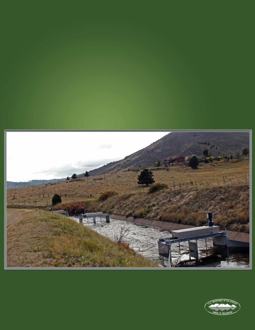
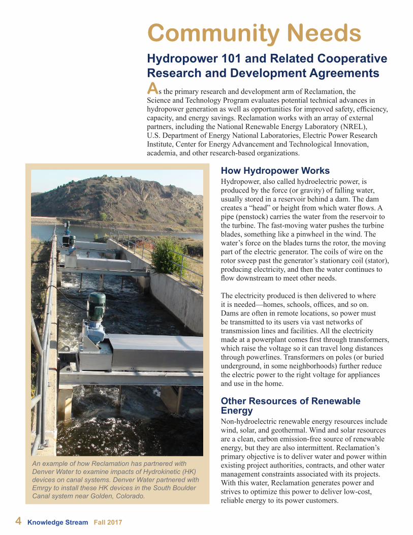
An example of how Reclamation has partnered with Denver Water to examine impacts of Hydrokinetic (HK) devices on canal systems. Denver Water partnered with Emrgy to install these HK devices in the South Boulder Canal system near Golden, Colorado.
How Hydropower Works Hydropower, also called hydroelectric power, is produced by the force (or gravity) of falling water, usually stored in a reservoir behind a dam. The dam creates a “head” or height from which water flows. A pipe (penstock) carries the water from the reservoir to the turbine. The fast-moving water pushes the turbine blades, something like a pinwheel in the wind. The water’s force on the blades turns the rotor, the moving part of the electric generator. The coils of wire on the rotor sweep past the generator’s stationary coil (stator), producing electricity, and then the water continues to flow downstream to meet other needs.
The electricity produced is then delivered to where it is needed—homes, schools, offices, and so on. Dams are often in remote locations, so power must be transmitted to its users via vast networks of transmission lines and facilities. All the electricity made at a powerplant comes first through transformers, which raise the voltage so it can travel long distances through powerlines. Transformers on poles (or buried underground, in some neighborhoods) further reduce the electric power to the right voltage for appliances and use in the home.
Other Resources of Renewable Energy Non-hydroelectric renewable energy resources include wind, solar, and geothermal. Wind and solar resources are a clean, carbon emission-free source of renewable energy, but they are also intermittent. Reclamation’s primary objective is to deliver water and power within existing project authorities, contracts, and other water management constraints associated with its projects. With this water, Reclamation generates power and strives to optimize this power to deliver low-cost, reliable energy to its power customers.
Cooperative Research and Development Agreements Researching new technologies and adapting industry technologies to Reclamation’s unique facilities is vital for providing hydropower that can integrate into an increasingly complex power grid and meet future demands within a changing system.
As part of the Federal Government’s Technology Transfer Authorities, Reclamation entered into two hydropower-related Cooperative Research and Development Agreements (CRADAs) during the first quarter of 2017. These authorities and agreements allow Reclamation to partner with the private sector to optimize resources and share expertise within Reclamation facilities that act as living laboratories when there is joint interest in exploring solutions to Reclamation’s and industries’ unique problems. These relationships can lead to industry-wide solutions.
www.usbr.gov/research 5
R&D Contact Erin ForakerHydropower and Infrastructure Research [email protected]
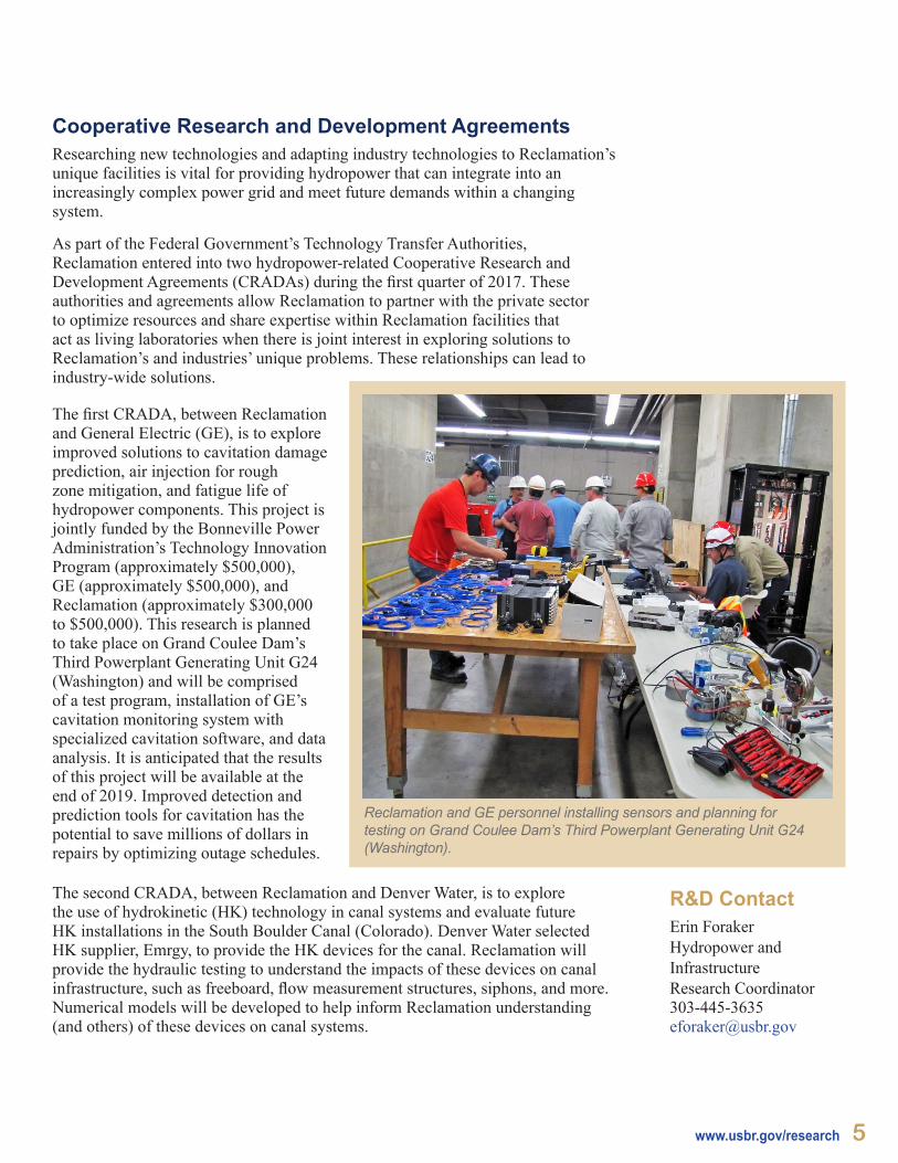
The first CRADA, between Reclamation and General Electric (GE), is to explore improved solutions to cavitation damage prediction, air injection for rough zone mitigation, and fatigue life of hydropower components. This project is jointly funded by the Bonneville Power Administration’s Technology Innovation Program (approximately $500,000), GE (approximately $500,000), and Reclamation (approximately $300,000 to $500,000). This research is planned to take place on Grand Coulee Dam’s Third Powerplant Generating Unit G24 (Washington) and will be comprised of a test program, installation of GE’s cavitation monitoring system with specialized cavitation software, and data analysis. It is anticipated that the results of this project will be available at the end of 2019. Improved detection and prediction tools for cavitation has the potential to save millions of dollars in repairs by optimizing outage schedules.
Reclamation and GE personnel installing sensors and planning for testing on Grand Coulee Dam’s Third Powerplant Generating Unit G24 (Washington).
The second CRADA, between Reclamation and Denver Water, is to explore the use of hydrokinetic (HK) technology in canal systems and evaluate future HK installations in the South Boulder Canal (Colorado). Denver Water selected HK supplier, Emrgy, to provide the HK devices for the canal. Reclamation will provide the hydraulic testing to understand the impacts of these devices on canal infrastructure, such as freeboard, flow measurement structures, siphons, and more. Numerical models will be developed to help inform Reclamation understanding (and others) of these devices on canal systems.
6 Knowledge Stream Fall 2017
Key Perspectives Memorandum of Understanding for Hydropower
Featured in the summer 2014 Knowledge Stream, the Memorandum of Understanding for Hydropower (MOU) advances reliable, affordable, and environmentally sustainable hydropower through a collaborative interagency framework across the U.S. Department of the Interior (DOI), U.S. Department of Energy (DOE), and the Department of the Army through the U.S. Army Corps of Engineers (USACE) (collectively, the “Agencies”). DOI’s MOU participation is coordinated through Reclamation.
The Agencies executed the MOU in 2010 and published an MOU Two-Year Progress Report in 2012. A renewal agreement was executed in 2015, extending the MOU through 2020. Accompanying the 2015 renewal agreement, an MOU Sustainable Hydropower Action Plan (Phase II) was published, identifying 5 MOU priority areas and 21 supporting action items to be pursued by the Agencies through 2020. The phase II priority areas include:
● Technology Development ● Asset Management ● Hydropower Sustainability ● Quantifying Hydropower Capabilities and Value in Power Systems ● Information Sharing, Coordination, and Strategic Planning
The MOU allows Reclamation to leverage DOE and USACE expertise and resources to meet Reclamation mission needs. Reclamation intends to continue working under this collaborative framework to more effectively fulfill mission requirements in hydropower.
In addition, the Agencies have drafted an MOU Two-Year Progress Report and Update, which highlights 2015 renewal agreement accomplishments and identifies new action items within the phase II priority areas. It is anticipated that the update will be published in fall 2017.Key Reclamation products delivered through the 2015 renewal agreement include:
● Federal Replacements Units, Service Lives, Factors Book (Replacements Book) (2017). Reclamation partnered with USACE and DOE Power Marketing Administrations to publish the 2017 Replacements Book (an update to the 2006 edition). The Replacements Book identifies critical water resource and power system units of property and associated service lives to inform the planning, budgeting, and repayment of power system maintenance, replacements, and refurbishment activities. The Replacements Book supports the management of Federal hydropower assets and promotes consistent financial reporting and rate setting processes across the Federal hydropower community (see “more information”).
● Pump and Operational Efficiency and Evaluation Report (2017). Opportunities exist to optimize Reclamation-owned pumping assets to curb electricity demand and deliver additional value to projects, operating partners, and customer groups while continuing to meet all contractual, water delivery commitments. To evaluate these opportunities, Reclamation coordinated with the Agencies to publish the 2017 Pump and Operational Efficiency and Evaluation report. The report investigates said opportunities at Reclamation’s Central Arizona Project (CAP) pumping plants.
More InformationHydropower Program website: www.usbr.gov/power
Replacement Book:www.usbr.gov/power/data/data.html
An Irrigation Canal Case Study:www.energy.gov/eere/water/downloads/assessing-and-testing-hydrokinetic-turbine-performance-and-effects-open-channel
—continued on page 7
ContactClark BishopProgram Analyst Reclamation’s Power Resources Office [email protected]
www.usbr.gov/research 7
With input from CAP’s operating partner, the Central Arizona Water Conservancy District, the report identifies refurbishment opportunities that deliver energy savings and positive benefit-cost ratios; and opportunities to deploy demand-side management by leveraging excess canal capacity, shifting water delivery schedules, and installing variable frequency drives. In addition to the report, an Excel Operations Tool was developed to conduct ad-hoc analyses of other pumping systems. Reclamation intends to use the report findings and operations tool to evaluate future Reclamation projects in collaboration with its operating partners.
● Assessing and Testing Hydrokinetic Turbine Performance and Effects on Open Channel Hydrodynamics: An Irrigation Canal Case Study (2017). Whereas irrigation canals show potential for hydrokinetic (HK) devices, a need exists to better understand this potential—specifically, the impacts of HK deployment on canal operations. In response to this need, Reclamation partnered with DOE and the Sandia National Laboratories to publish the 2017 Assessing and Testing Hydrokinetic Turbine Performance and Effects on Open Channel Hydrodynamics: An Irrigation Canal Case Study (see “more information”). The study provides an overview of the main considerations, tools, and assessment methods to evaluate HK device performance and hydrodynamic effects on open channel systems based on observations drawn from an HK installation at Reclamation’s Roza Main Canal (Washington). Additional testing at Roza Main Canal is scheduled in 2018. As referenced in the previous “Hydropower 101 and Related Cooperative Research and Development Agreements” article, Reclamation is partnering with Denver Water to explore the use of HK technology in canal systems and evaluate future HK installations in the South Boulder Canal (Colorado). Denver Water selected HK supplier, Emrgy, to provide the HK devices for the canal.
In addition to these completed and delivered products, Reclamation is currently working with MOU partners on a number of other ongoing projects, including:
● Quantifying the flexible dispatch and ancillary service capabilities of hydropower assets to ensure Reclamation facilities are properly valued within existing power systems.
● Improving hydropower data acquisition and storage processes to meet emerging business needs and DOI/Reclamation data sharing initiatives.
● Sharing best practices, lessons learned, and performance metrics with MOU partners to improve operational performance, given evolving water and power system demands.
Additional completed MOU products and all ongoing work will be described in the forthcoming MOU Two-Year Progress Report and Update. Reclamation’s Hydropower Program website hosts all MOU documents (see “more information”).
—continued from page 6
In Brief:The Research and Development Office participated in the Pump and Operational Efficiency Study in a technical advisory role, and led the testing efforts and partnership development with Instream Energy Systems and Sandia National Laboratories in the Hydrokinetic Case Study in Roza Canal.
Current Research and Partnerships
8 Knowledge Stream Fall 2017
Three-Dimensional Building Information Modeling of Glen Canyon Dam and Powerplant
Since 1902, Reclamation constructed numerous dams and powerplants using traditional hand drafting to produce two-dimensional (2-D) engineering drawings for design and construction activities. Hundreds or thousands of drawings were created for each facility. A major weakness of engineering drawings is their focus on individual components or systems with little reference to adjacent or complementary systems.
ContributorsTalmadge OxfordPower ManagerReclamation’s Upper Colorado [email protected]
Jason TuckerEngineering and Project Services SupervisorReclamation’s Upper Colorado [email protected]
Introduced in the 1980s, computer aided design (CAD) has transitioned from a replacement for hand drafting to the creation of 3-D facility models. These models are used for building information modeling (BIM) that incorporates planning, design, construction, and lifecycle management. This Reclamation Science and Technology Program-funded research project set out to create an intelligent facility-wide model of Glen Canyon Dam and Powerplant, a national critical infrastructure facility located in Page, Arizona. It serves as a prototype to develop Reclamation expertise, best practices, guidelines, and procedures for completion of similar projects by Reclamation.
Reclamation partnered with Autodesk, Inc. (Autodesk), creator of the AutoCAD software family, for this research project. (These software products are used daily in offices throughout Reclamation.) The three research project phases are:
1. Capture the exterior of the dam, and interior and exterior of the powerplant, using laser scanning equipment.
2. Employ aerial photogrammetry and underwater sonar to capture the upstream and downstream faces of the dam, as well as conditions a quarter mile upstream of the damsite.
3. Create an intelligent 3-D model of the facility with overlays for operation and maintenance (O&M), facility management, security, power distribution, and geographic information system (GIS).
Reclamation and Autodesk completed phases 1 and 2 onsite in the fall of 2016. Data collection equipment included laser scanners, a remotely operated vehicle with a mounted sonar scanner, survey instruments, photographic cameras, an unmanned
—continued on page 9
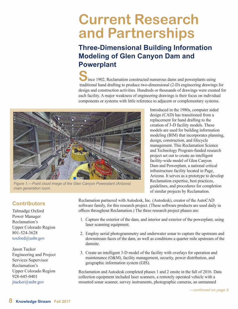
Figure 1.—Point cloud image of the Glen Canyon Powerplant (Arizona) main generation room.
www.usbr.gov/research 9
Contact David Winslow Civil Engineer Reclamation’s Upper Colorado [email protected]
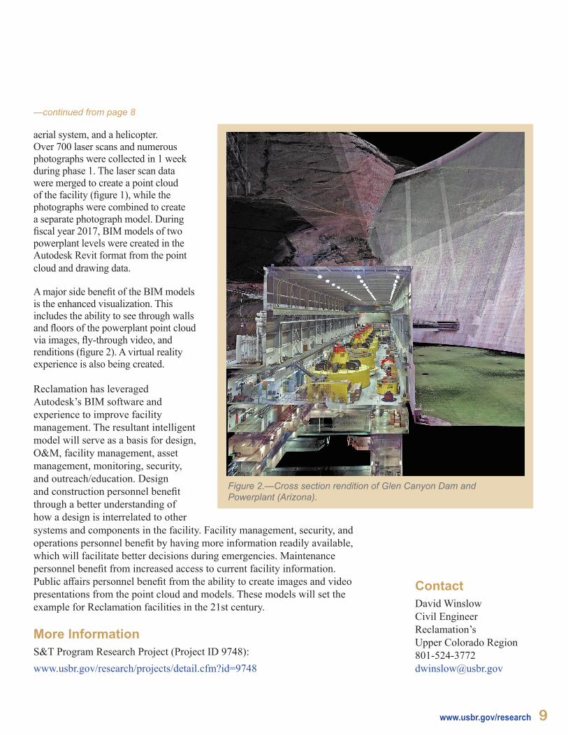
A major side benefit of the BIM models is the enhanced visualization. This includes the ability to see through walls and floors of the powerplant point cloud via images, fly-through video, and renditions (figure 2). A virtual reality experience is also being created.
Reclamation has leveraged Autodesk’s BIM software and experience to improve facility management. The resultant intelligent model will serve as a basis for design, O&M, facility management, asset management, monitoring, security, and outreach/education. Design and construction personnel benefit through a better understanding of how a design is interrelated to other
—continued from page 8
aerial system, and a helicopter. Over 700 laser scans and numerous photographs were collected in 1 week during phase 1. The laser scan data were merged to create a point cloud of the facility (figure 1), while the photographs were combined to create a separate photograph model. During fiscal year 2017, BIM models of two powerplant levels were created in the Autodesk Revit format from the point cloud and drawing data.
—continued on page 9
systems and components in the facility. Facility management, security, and operations personnel benefit by having more information readily available, which will facilitate better decisions during emergencies. Maintenance personnel benefit from increased access to current facility information. Public affairs personnel benefit from the ability to create images and video presentations from the point cloud and models. These models will set the example for Reclamation facilities in the 21st century.
Figure 2.—Cross section rendition of Glen Canyon Dam and Powerplant (Arizona).
More InformationS&T Program Research Project (Project ID 9748):www.usbr.gov/research/projects/detail.cfm?id=9748
10 Knowledge Stream Fall 2017
Personal Protective Grounds
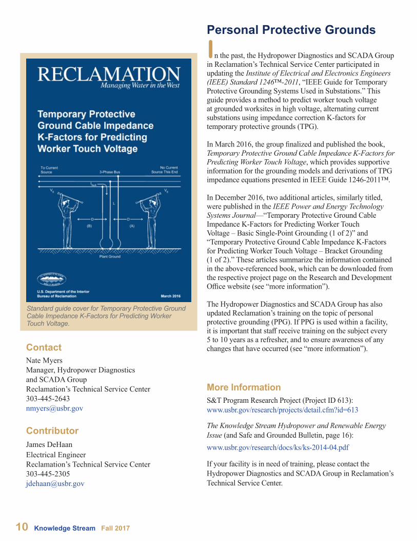
In the past, the Hydropower Diagnostics and SCADA Group in Reclamation’s Technical Service Center participated in updating the Institute of Electrical and Electronics Engineers (IEEE) Standard 1246™-2011, “IEEE Guide for Temporary Protective Grounding Systems Used in Substations.” This guide provides a method to predict worker touch voltage at grounded worksites in high voltage, alternating current substations using impedance correction K-factors for temporary protective grounds (TPG). In March 2016, the group finalized and published the book, Temporary Protective Ground Cable Impedance K-Factors for Predicting Worker Touch Voltage, which provides supportive information for the grounding models and derivations of TPG impedance equations presented in IEEE Guide 1246-2011™.
In December 2016, two additional articles, similarly titled, were published in the IEEE Power and Energy Technology Systems Journal—“Temporary Protective Ground Cable Impedance K-Factors for Predicting Worker Touch Voltage – Basic Single-Point Grounding (1 of 2)” and “Temporary Protective Ground Cable Impedance K-Factors for Predicting Worker Touch Voltage – Bracket Grounding (1 of 2).” These articles summarize the information contained in the above-referenced book, which can be downloaded from the respective project page on the Research and Development Office website (see “more information”).
The Hydropower Diagnostics and SCADA Group has also updated Reclamation’s training on the topic of personal protective grounding (PPG). If PPG is used within a facility, it is important that staff receive training on the subject every 5 to 10 years as a refresher, and to ensure awareness of any changes that have occurred (see “more information”).
More InformationS&T Program Research Project (Project ID 613): www.usbr.gov/research/projects/detail.cfm?id=613
The Knowledge Stream Hydropower and Renewable Energy Issue (and Safe and Grounded Bulletin, page 16):www.usbr.gov/research/docs/ks/ks-2014-04.pdf
If your facility is in need of training, please contact the Hydropower Diagnostics and SCADA Group in Reclamation’s Technical Service Center.
Standard guide cover for Temporary Protective Ground Cable Impedance K-Factors for Predicting Worker Touch Voltage.
ContactNate MyersManager, Hydropower Diagnostics and SCADA Group Reclamation’s Technical Service [email protected]
ContributorJames DeHaanElectrical EngineerReclamation’s Technical Service [email protected]
www.usbr.gov/research 11
Ester Fluid Flammability Testing
More Information S&T Program Research Project(Project ID 1606):www.usbr.gov/research/projects/detail.cfm?id=1606
ContactNate MyersManager, Hydropower Diagnostics and SCADA Group Reclamation’s Technical Service Center303-445-2643 [email protected]
ContributorBen FewElectrical EngineerReclamation’s Technical Service [email protected]
Reclamation is always examining new and improved ways to ensure the power produced from its hydrogenerators is delivered to distribution partners. A Reclamation Science and Technology Program research project is examining the use of Ester fluid as a replacement for mineral oil in power transformers to reduce risks associated with environmental impact and fire mitigation. The voltage class of the equipment has traditionally limited the use of Ester fluids; however, Reclamation is looking to replace higher voltage class transformers using Ester fluid as the insulating medium.
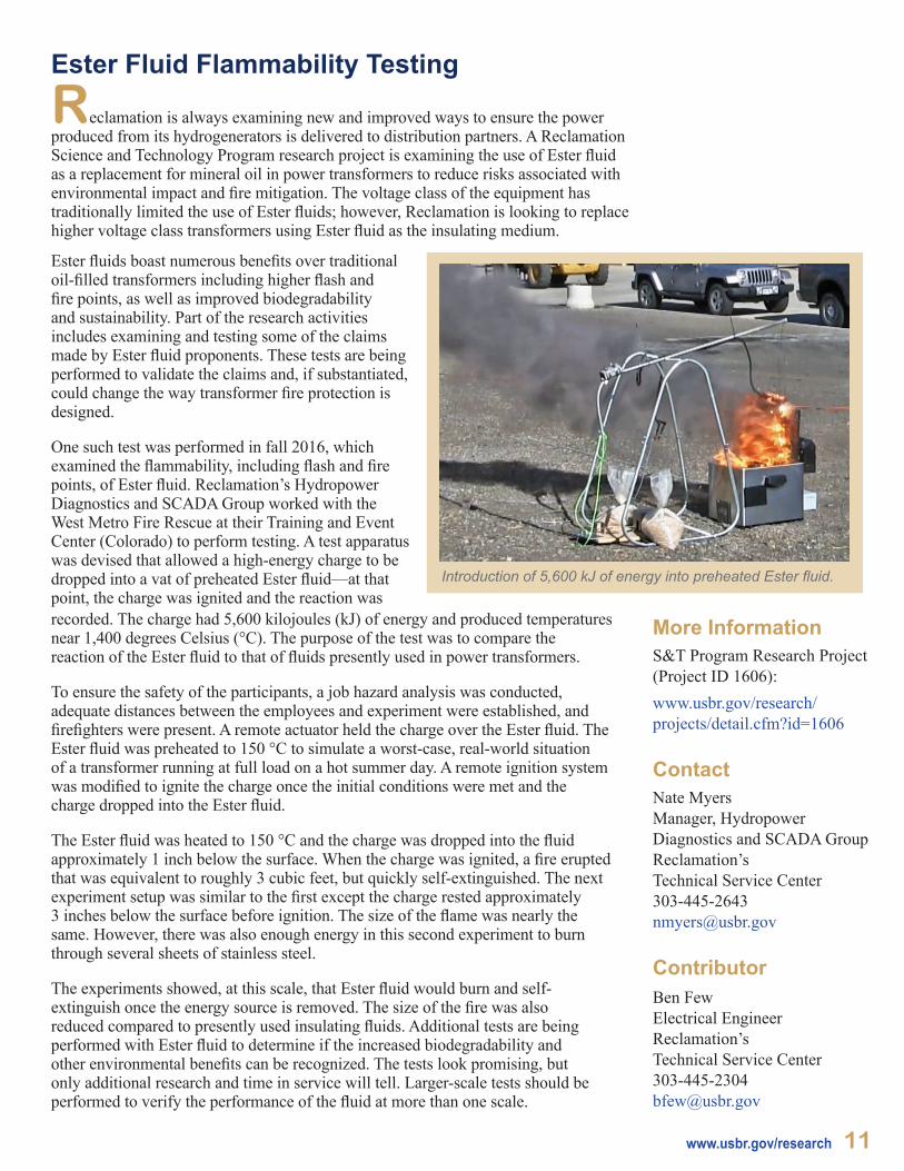
Introduction of 5,600 kJ of energy into preheated Ester fluid.
Ester fluids boast numerous benefits over traditional oil-filled transformers including higher flash and fire points, as well as improved biodegradability and sustainability. Part of the research activities includes examining and testing some of the claims made by Ester fluid proponents. These tests are being performed to validate the claims and, if substantiated, could change the way transformer fire protection is designed.
One such test was performed in fall 2016, which examined the flammability, including flash and fire points, of Ester fluid. Reclamation’s Hydropower Diagnostics and SCADA Group worked with the West Metro Fire Rescue at their Training and Event Center (Colorado) to perform testing. A test apparatus was devised that allowed a high-energy charge to be dropped into a vat of preheated Ester fluid—at that point, the charge was ignited and the reaction was recorded. The charge had 5,600 kilojoules (kJ) of energy and produced temperatures near 1,400 degrees Celsius (°C). The purpose of the test was to compare the reaction of the Ester fluid to that of fluids presently used in power transformers.
To ensure the safety of the participants, a job hazard analysis was conducted, adequate distances between the employees and experiment were established, and firefighters were present. A remote actuator held the charge over the Ester fluid. The Ester fluid was preheated to 150 °C to simulate a worst-case, real-world situation of a transformer running at full load on a hot summer day. A remote ignition system was modified to ignite the charge once the initial conditions were met and the charge dropped into the Ester fluid.
The Ester fluid was heated to 150 °C and the charge was dropped into the fluid approximately 1 inch below the surface. When the charge was ignited, a fire erupted that was equivalent to roughly 3 cubic feet, but quickly self-extinguished. The next experiment setup was similar to the first except the charge rested approximately 3 inches below the surface before ignition. The size of the flame was nearly the same. However, there was also enough energy in this second experiment to burn through several sheets of stainless steel.
The experiments showed, at this scale, that Ester fluid would burn and self-extinguish once the energy source is removed. The size of the fire was also reduced compared to presently used insulating fluids. Additional tests are being performed with Ester fluid to determine if the increased biodegradability and other environmental benefits can be recognized. The tests look promising, but only additional research and time in service will tell. Larger-scale tests should be performed to verify the performance of the fluid at more than one scale.

Metal Fiber BrushesThroughout Reclamation, and the power generating industry as a whole, carbon brushes are used to transfer electrical current from a stationary component to a rotating component. In Reclamation, carbon brushes are primarily used as part of the excitation system of hydrogenerators (an excitation system of a synchronous generator makes it possible to supply the energy generated by a turbine to the power grid). Carbon brushes are also a regular maintenance item.
The problems with carbon brushes are their vulnerability to powerplant environment change and conductive wear material generation. In addition, a specialized knowledge is required to maintain them. Contaminates can cause the carbon brushes to wear at a rapid rate, possibly causing an unscheduled outage. Contaminate sources, in most cases, are from oil mist that escapes from generator bearing tubs and collects on the carbon brushes. Other sources of contaminants are volatile organic compounds released from painting or Room-Temperature-Vulcanizing (RTV) silicones near the carbon brushes, high or very low humidity, and hydrogen sulfide (H2S) that naturally occurs at many Reclamation dam locations.
Metal fiber brushes (MFBs) are an old idea that are—with help from modern technology—a potential solution for replacing carbon brushes. MFBs came before the invention of carbon brushes. Initially, they were metal braids that lay against a rotating component to conduct current. Recent advancements have resulted in an MFB that is now made from thousands of silver hair-like conductors inline and held together in a bundle to carry large amounts of current to rotating components.
More InformationS&T Program Research Project (Project ID 6711):www.usbr.gov/research/projects/detail.cfm?id=6711
Contact the Hydropower Diagnostics and SCADA Group in Reclamation’s Technical Service Center for any brush issues.
Contact Nate MyersManager, Hydropower Diagnostics and SCADA Group Reclamation’s Technical Service Center303-445-2643 [email protected]
ContributorBen FewElectrical EngineerReclamation’s Technical Service Center303-445-2304 [email protected]
12 Knowledge Stream Fall 2017
The face of a MFB showing thousands of silver hair-like conductors.
After rigorous testing, both in the laboratory and in the field, the following three conclusions were drawn:
1. Silver MFBs are not suitable for operating on steel slip rings.
2. Silver MFBs are suitable for operating on silver-plated steel slip rings and show promise for low-contamination environments.
3. Silver MFBs are not suitable for supplying electrical power from the excitation system through slip rings to field windings in Reclamation facilities.
A full report is available upon request on the indepth testing that was performed on MFB technology. Presently, MFBs will not replace carbon brushes used as part of hydrogenerator excitation systems at Reclamation facilities, but there are applications where the MFBs show promise.
More Information Hydropower Modeling Challenges Technical Report: www.nrel.gov/docs/fy17osti/68231.pdf
ContactsTodd Gaston Economist Reclamation’s Technical Service [email protected]
James Anders Economist Reclamation’s Technical Service [email protected]
CollaboratorNational Renewable Energy Laboratory
Hydropower Modeling Challenges
Hydropower facilities can provide a key source of flexibility for maintaining electric grid stability—particularly those with a high penetration of variable energy generation such as wind and solar. As more variable renewable generation sources come online, a better understanding of the capabilities and limitations of hydropower resources is important for efficient grid planning. However, modeling hydropower facilities is difficult due to a wide variety of constraints that can be broadly categorized as environmental (e.g., those imposed to limit negative impacts on the environment), operational (e.g., limitations of the generation equipment), and regulatory (e.g., binding obligations to water users). Through an interagency agreement conceived by Reclamation’s Research and Development Office, Reclamation economists teamed up with the U.S. Department of Energy’s National Renewable Energy Laboratory to research ways to improve the modeling of hydropower facilities by cataloging and accommodating these constraints in power system models.
This research identified many potential opportunities to better represent hydropower in power system models. The published technical report (see “more information”) focuses on three such opportunities: 1) incorporating better hydrological data, 2) improving existing representations and constraints for hydropower facilities, and 3) linking power system models to watershed models (specifically, RiverWare [a river and reservoir modeling tool). In experimental model runs, all three improvement categories independently demonstrated an increased ability to accurately represent the capabilities of hydropower facilities
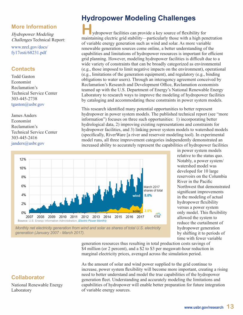
in power system models relative to the status quo. Notably, a power system/watershed model was developed for 10 large reservoirs on the Columbia River in the Pacific Northwest that demonstrated significant improvements in the modeling of actual hydropower flexibility versus a power system only model. This flexibility allowed the system to reduce the curtailment of hydropower generation by shifting it to periods of time with fewer variable
generation resources thus resulting in total production costs savings of $4 million (or 2 percent), and a $2 to $3 per megawatt-hour reduction in marginal electricity prices, averaged across the simulation period.
As the amount of solar and wind power supplied to the grid continue to increase, power system flexibility will become more important, creating a rising need to better understand and model the true capabilities of the hydropower generation fleet. Understanding and accurately modeling the limitations and capabilities of hydropower will enable better preparation for future integration of variable energy sources.
Monthly net electricity generation from wind and solar as shares of total U.S. electricity generation (January 2007 - March 2017).
www.usbr.gov/research 13
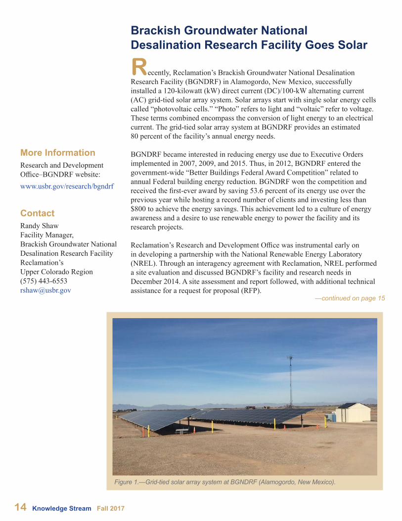
Recently, Reclamation’s Brackish Groundwater National Desalination Research Facility (BGNDRF) in Alamogordo, New Mexico, successfully installed a 120-kilowatt (kW) direct current (DC)/100-kW alternating current (AC) grid-tied solar array system. Solar arrays start with single solar energy cells called “photovoltaic cells.” “Photo” refers to light and “voltaic” refer to voltage. These terms combined encompass the conversion of light energy to an electrical current. The grid-tied solar array system at BGNDRF provides an estimated 80 percent of the facility’s annual energy needs.
BGNDRF became interested in reducing energy use due to Executive Orders implemented in 2007, 2009, and 2015. Thus, in 2012, BGNDRF entered the government-wide “Better Buildings Federal Award Competition” related to annual Federal building energy reduction. BGNDRF won the competition and received the first-ever award by saving 53.6 percent of its energy use over the previous year while hosting a record number of clients and investing less than $800 to achieve the energy savings. This achievement led to a culture of energy awareness and a desire to use renewable energy to power the facility and its research projects.
Reclamation’s Research and Development Office was instrumental early on in developing a partnership with the National Renewable Energy Laboratory (NREL). Through an interagency agreement with Reclamation, NREL performed a site evaluation and discussed BGNDRF’s facility and research needs in December 2014. A site assessment and report followed, with additional technical assistance for a request for proposal (RFP).
14 Knowledge Stream Fall 2017
More Information Research and Development Office–BGNDRF website: www.usbr.gov/research/bgndrf
Contact Randy ShawFacility Manager, Brackish Groundwater National Desalination Research FacilityReclamation’s Upper Colorado Region(575) [email protected]
Brackish Groundwater National Desalination Research Facility Goes Solar
Figure 1.—Grid-tied solar array system at BGNDRF (Alamogordo, New Mexico).
—continued on page 15
—continued on page 15
The system recently installed at BGNDRF is a grid-tied solar array consisting of 350 solar panels with a surface area of approximately 7,600 square feet (figure 1). The system is equipped with DC optimizers for each pair of solar panels so that solar panel performance of the entire array can be monitored on a website. BGNDRF staff make the interesting point that the solar array system is about the same capacity as that used on the International Space Station.
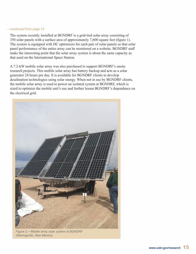
A 7.2-kW mobile solar array was also purchased to support BGNDRF’s onsite research projects. This mobile solar array has battery backup and acts as a solar generator 24 hours per day. It is available for BGNDRF clients to develop desalination technologies using solar energy. When not in use by BGNDRF clients, the mobile solar array is used to power an isolated system at BGNDRF, which is sized to optimize the mobile unit’s use and further lessen BGNDRF’s dependence on the electrical grid.
www.usbr.gov/research 15
Figure 2.—Mobile array solar system at BGNDRF (Alamogordo, New Mexico).
—continued from page 14

Visivolt—Noncontact Voltage Measurement to Improve Employee Safety
Powerplants present many hazards to the people working in them. In the vast majority of accidents, hindsight shows that most incidents could have been avoided. Many accidents around high-voltage equipment often arise due to the mistaken belief that the equipment is no longer energized. At first glance, these seem to be the easiest accidents to avoid, yet they still persist within the power industry. Passive voltage detection devices have been used in recent years to hedge risks of accidents such as these. The goal of these devices is to give clear indication of the presence of voltage while being self-contained (bird on a wire), passive (no batteries or external sources, and no need to tap into conductors for power), and reliable.
One device that meets this goal, and is commercially available, is the VisiVolt™ by ABB. This device has been completely tested within Reclamation laboratories through a Science and Technology Program research project, and a full report is available (see "more information"). The device is completely passive and consists only of a liquid-crystal display (LCD) screen and a single surface mount antenna. The antenna produces a voltage and activates the liquid crystals in the LCD screen in the presence of a strong electric field. LCD liquid crystal activation controls light reflection from the back surface of the display, producing the image of a lightning bolt. Because the strong electric field that causes the produced image is a result of high-voltage potentials, the lightning bolt only appears when equipment is energized. It is important to note, however, that while the device is good evidence of energization, it should not be used as proof of de-energization for switching or maintenance work.
For switching and maintenance work, de-energization can only be obtained following the facility “Hazardous Energy Control Program” as described in Facilities Instructions, Standards, and Techniques (FIST), Volume 1-1. For maintenance work, proof of de-energization can only be established by testing
VisiVolt™—a passive voltage-indicating device.
More InformationS&T Program Research Project (Project ID 613):www.usbr.gov/research/projects/detail.cfm?id=613
Contact Nate MyersManager, Hydropower Diagnostics and SCADA Group Reclamation’s Technical Service [email protected]
ContributorJacob LapennaElectrical EngineerReclamation’s Technical Service [email protected]
for the absence of nominal voltage using a recently tested indicating-type detector, and the application of personal protective grounds as described in FIST 5-1. Despite this limitation, at $500 per unit in low quantities, this device can be an effective way of providing one more level of protection—particularly during switching procedures in providing evidence of energization. For these types of foreseeable applications, the VisiVolt™ may be a step toward increased safety in Reclamation powerplants by indicating bus energization at rated voltage.
16 Knowledge Stream Fall 2017
www.usbr.gov/research 17
Addressing Localized Saturation of Generator Neutral Current Transformers
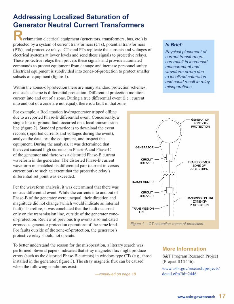
Reclamation electrical equipment (generators, transformers, bus, etc.) is protected by a system of current transformers (CTs), potential transformers (PTs), and protective relays. CTs and PTs replicate the currents and voltages of electrical systems at lower levels and send these signals to protective relays. These protective relays then process these signals and provide automated commands to protect equipment from damage and increase personnel safety. Electrical equipment is subdivided into zones-of-protection to protect smaller subsets of equipment (figure 1).
Within the zones-of-protection there are many standard protection schemes; one such scheme is differential protection. Differential protection monitors current into and out of a zone. During a true differential event (i.e., current into and out of a zone are not equal), there is a fault in that zone.
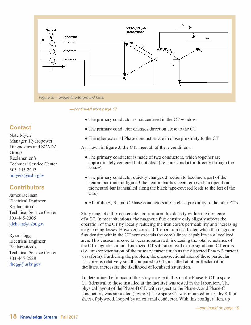
For example, a Reclamation hydrogenerator tripped offline due to a reported Phase-B differential event. Concurrently, a single-line-to-ground fault occurred on a local transmission line (figure 2). Standard practice is to download the event records (reported currents and voltages during the event), analyze the data, test the equipment, and inspect the equipment. During the analysis, it was determined that the event caused high currents on Phase-A and Phase-C of the generator and there was a distorted Phase-B current waveform in the generator. The distorted Phase-B current waveform mismatched its differential pair (current in versus current out) to such an extent that the protective relay’s differential set point was exceeded.
Per the waveform analysis, it was determined that there was no true differential event. While the currents into and out of Phase-B of the generator were unequal, their direction and magnitude did not change (which would indicate an internal fault). Therefore, it was concluded that the fault occurred only on the transmission line, outside of the generator zone-of-protection. Review of previous trip events also indicated erroneous generator protection operations of the same kind. For faults outside of the zone-of-protection, the generator’s protective relay should not operate.
Figure 1.—CT saturation zones-of-protection.
—continued on page 18
More Information S&T Program Research Project (Project ID 2446): www.usbr.gov/research/projects/detail.cfm?id=2446
To better understand the reason for the misoperation, a literary search was performed. Several papers indicated that stray magnetic flux might produce errors (such as the distorted Phase-B currents) in window-type CTs (e.g., those installed in the generator; figure 3). The stray magnetic flux can be caused when the following conditions exist:
In Brief:Physical placement of current transformers can result in increased measurement and waveform errors due to localized saturation and could result in relay misoperations.
● The primary conductor is not centered in the CT window
● The primary conductor changes direction close to the CT
● The other external Phase conductors are in close proximity to the CT
As shown in figure 3, the CTs meet all of these conditions:
● The primary conductor is made of two conductors, which together are approximately centered but not ideal (i.e., one conductor directly through the center).
● The primary conductor quickly changes direction to become a part of the neutral bar (note in figure 3 the neutral bar has been removed; in operation the neutral bar is installed along the black tape-covered leads to the left of the CTs).
● All of the A, B, and C Phase conductors are in close proximity to the other CTs.
18 Knowledge Stream Fall 2017
—continued on page 19
—continued from page 17
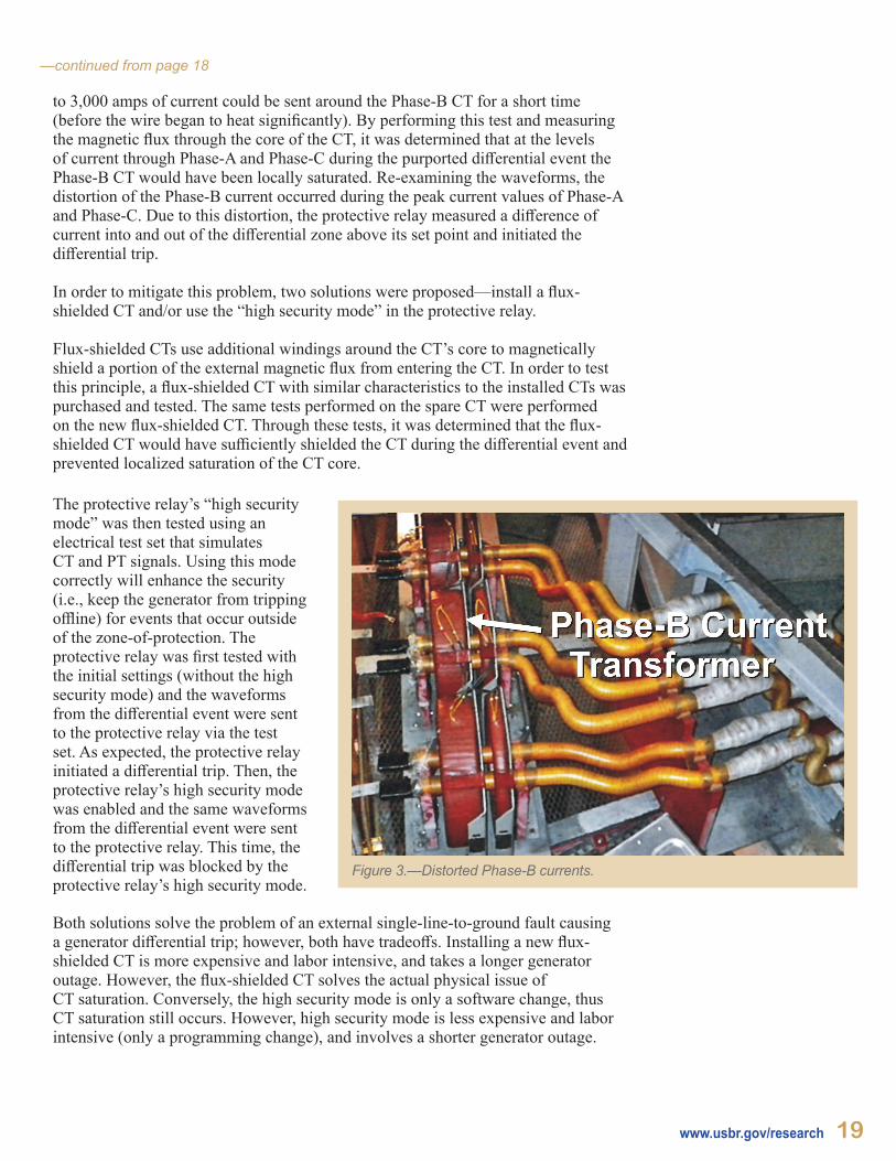
Stray magnetic flux can create non-uniform flux density within the iron core of a CT. In most situations, the magnetic flux density only slightly affects the operation of the CT by locally reducing the iron core’s permeability and increasing magnetizing losses. However, correct CT operation is affected when the magnetic flux density within the CT core exceeds the core’s linear capability in a localized area. This causes the core to become saturated, increasing the total reluctance of the CT magnetic circuit. Localized CT saturation will cause significant CT errors (i.e., misrepresentation of the primary current such as the distorted Phase-B current waveform). Furthering the problem, the cross-sectional area of these particular CT cores is relatively small compared to CTs installed at other Reclamation facilities, increasing the likelihood of localized saturation.
To determine the impact of this stray magnetic flux on the Phase-B CT, a spare CT (identical to those installed at the facility) was tested in the laboratory. The physical layout of the Phase-B CT, with respect to the Phase-A and Phase-C conductors, was simulated (figure 3). The spare CT was mounted in a 4- by 8-foot sheet of plywood, looped by an external conductor. With this configuration, up
ContactNate Myers Manager, Hydropower Diagnostics and SCADA Group Reclamation’s Technical Service [email protected]
ContributorsJames DeHaanElectrical EngineerReclamation’s Technical Service Center303-445-2305 [email protected]
Ryan HoggElectrical EngineerReclamation’s Technical Service Center303-445-2528 [email protected]
Figure 2.—Single-line-to-ground fault.
—continued from page 18
to 3,000 amps of current could be sent around the Phase-B CT for a short time (before the wire began to heat significantly). By performing this test and measuring the magnetic flux through the core of the CT, it was determined that at the levels of current through Phase-A and Phase-C during the purported differential event the Phase-B CT would have been locally saturated. Re-examining the waveforms, the distortion of the Phase-B current occurred during the peak current values of Phase-A and Phase-C. Due to this distortion, the protective relay measured a difference of current into and out of the differential zone above its set point and initiated the differential trip.
In order to mitigate this problem, two solutions were proposed—install a flux-shielded CT and/or use the “high security mode” in the protective relay.
Flux-shielded CTs use additional windings around the CT’s core to magnetically shield a portion of the external magnetic flux from entering the CT. In order to test this principle, a flux-shielded CT with similar characteristics to the installed CTs was purchased and tested. The same tests performed on the spare CT were performed on the new flux-shielded CT. Through these tests, it was determined that the flux-shielded CT would have sufficiently shielded the CT during the differential event and prevented localized saturation of the CT core.
The protective relay’s “high security mode” was then tested using an electrical test set that simulates CT and PT signals. Using this mode correctly will enhance the security (i.e., keep the generator from tripping offline) for events that occur outside of the zone-of-protection. The protective relay was first tested with the initial settings (without the high security mode) and the waveforms from the differential event were sent to the protective relay via the test set. As expected, the protective relay initiated a differential trip. Then, the protective relay’s high security mode was enabled and the same waveforms from the differential event were sent to the protective relay. This time, the differential trip was blocked by the protective relay’s high security mode.
Both solutions solve the problem of an external single-line-to-ground fault causing a generator differential trip; however, both have tradeoffs. Installing a new flux-shielded CT is more expensive and labor intensive, and takes a longer generator outage. However, the flux-shielded CT solves the actual physical issue of CT saturation. Conversely, the high security mode is only a software change, thus CT saturation still occurs. However, high security mode is less expensive and labor intensive (only a programming change), and involves a shorter generator outage.
www.usbr.gov/research 19
Figure 3.—Distorted Phase-B currents.
20 Knowledge Stream Fall 2017
Featured FacesEngineers Across Reclamation That Support Hydropower Research
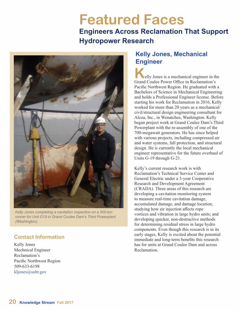
Kelly Jones is a mechanical engineer in the Grand Coulee Power Office in Reclamation’s Pacific Northwest Region. He graduated with a Bachelors of Science in Mechanical Engineering and holds a Professional Engineer license. Before starting his work for Reclamation in 2016, Kelly worked for more than 20 years as a mechanical/civil/structural design engineering consultant for Alcoa, Inc., in Wenatchee, Washington. Kelly began project work at Grand Coulee Dam’s Third Powerplant with the re-assembly of one of the 700-megawatt generators. He has since helped with various projects, including compressed air and water systems, fall protection, and structural design. He is currently the local mechanical engineer representative for the future overhaul of Units G-19 through G-21.
Kelly’s current research work is with Reclamation’s Technical Service Center and General Electric under a 3-year Cooperative Research and Development Agreement (CRADA). Three areas of this research are developing a cavitation monitoring system to measure real-time cavitation damage, accumulated damage, and damage location; studying how air injection affects rope vortices and vibration in large hydro units; and developing quicker, non-destructive methods for determining residual stress in large hydro components. Even though this research is in its early stages, Kelly is excited about the potential immediate and long-term benefits this research has for units at Grand Coulee Dam and across Reclamation.
Kelly Jones completing a cavitation inspection on a 500-ton runner for Unit G19 in Grand Coulee Dam’s Third Powerplant (Washington).
Contact InformationKelly JonesMechnical EngineerReclamation’s Pacific Northwest [email protected]
Kelly Jones, Mechanical Engineer
Eric Eastment, Electrical Engineer
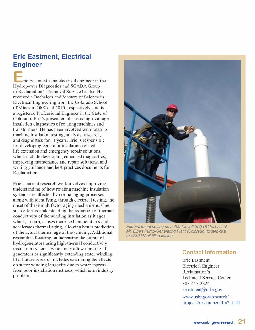
Eric Eastment is an electrical engineer in the Hydropower Diagnostics and SCADA Group in Reclamation’s Technical Service Center. He received a Bachelors and Masters of Science in Electrical Engineering from the Colorado School of Mines in 2002 and 2010, respectively, and is a registered Professional Engineer in the State of Colorado. Eric’s present emphasis is high-voltage insulation diagnostics of rotating machines and transformers. He has been involved with rotating machine insulation testing, analysis, research, and diagnostics for 11 years. Eric is responsible for developing generator insulation-related life extension and emergency repair solutions, which include developing enhanced diagnostics, improving maintenance and repair solutions, and writing guidance and best practices documents for Reclamation.
Eric’s current research work involves improving understanding of how rotating machine insulation systems are affected by normal aging processes along with identifying, through electrical testing, the onset of these multifactor aging mechanisms. One such effort is understanding the reduction of thermal conductivity of the winding insulation as it ages which, in turn, causes increased temperatures and accelerates thermal aging, allowing better prediction of the actual thermal age of the winding. Additional research is focusing on increasing the output of hydrogenerators using high-thermal conductivity insulation systems, which may allow uprating of generators or significantly extending stator winding life. Future research includes examining the effects on stator winding longevity due to water ingress from poor installation methods, which is an industry problem.
Eric Eastment setting up a 400-kilovolt (kV) DC test set at Mt. Elbert Pump-Generating Plant (Colorado) to step-test the 230-kV oil-filled cables.
www.usbr.gov/research 21
Contact InformationEric EastmentElectrical EngineerReclamation’s Technical Service [email protected]/research/projects/researcher.cfm?id=21
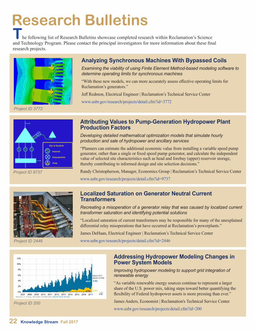
The following list of Research Bulletins showcase completed research within Reclamation’s Science and Technology Program. Please contact the principal investigators for more information about these final research projects.
Research Bulletins
Analyzing Synchronous Machines With Bypassed CoilsExamining the viability of using Finite Element Method-based modeling software to determine operating limits for synchronous machines“With these new models, we can more accurately assess effective operating limits for Reclamation’s generators.”Jeff Redmon, Electrical Engineer | Reclamation’s Technical Service Centerwww.usbr.gov/research/projects/detail.cfm?id=3772
Project ID 2446
Project ID 9737
Project ID 3772
Project ID 200
22 Knowledge Stream Fall 2017
Attributing Values to Pump-Generation Hydropower Plant Production FactorsDeveloping detailed mathematical optimization models that simulate hourly production and sale of hydropower and ancillary services“Planners can estimate the additional economic value from installing a variable speed pump generator, rather than a single or fixed speed pump generator, and calculate the independent value of selected site characteristics such as head and forebay (upper) reservoir storage, thereby contributing to informed design and site selection decisions.”Randy Christopherson, Manager, Economics Group | Reclamation’s Technical Service Centerwww.usbr.gov/research/projects/detail.cfm?id=9737
Localized Saturation on Generator Neutral Current TransformersRecreating a misoperation of a generator relay that was caused by localized current transformer saturation and identifying potential solutions“Localized saturation of current transformers may be responsible for many of the unexplained differential relay misoperations that have occurred at Reclamation’s powerplants.”James DeHaan, Electrical Engineer | Reclamation’s Technical Service Center www.usbr.gov/research/projects/detail.cfm?id=2446
Addressing Hydropower Modeling Changes in Power System ModelsImproving hydropower modeling to support grid integration of renewable energy“As variable renewable energy sources continue to represent a larger share of the U.S. power mix, taking steps toward better quantifying the flexibility of Federal hydropower assets is more pressing than ever.” James Anders, Economist | Reclamation's Technical Service Centerwww.usbr.gov/research/projects/detail.cfm?id=200
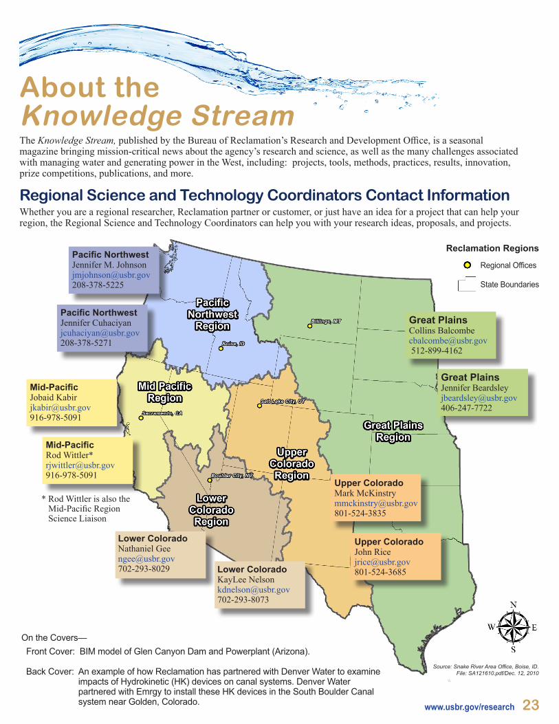
Regional Science and Technology Coordinators Contact InformationWhether you are a regional researcher, Reclamation partner or customer, or just have an idea for a project that can help your region, the Regional Science and Technology Coordinators can help you with your research ideas, proposals, and projects.
On the Covers— Front Cover: BIM model of Glen Canyon Dam and Powerplant (Arizona). Back Cover: An example of how Reclamation has partnered with Denver Water to examine impacts of Hydrokinetic (HK) devices on canal systems. Denver Water partnered with Emrgy to install these HK devices in the South Boulder Canal system near Golden, Colorado.
About the Knowledge StreamThe Knowledge Stream, published by the Bureau of Reclamation’s Research and Development Office, is a seasonal magazine bringing mission-critical news about the agency’s research and science, as well as the many challenges associated with managing water and generating power in the West, including: projects, tools, methods, practices, results, innovation, prize competitions, publications, and more.
www.usbr.gov/research 23
* Rod Wittler is also the Mid-Pacific Region
Science Liaison
Upper ColoradoMark [email protected]
Upper ColoradoJohn [email protected]
Lower ColoradoNathaniel [email protected] Lower Colorado
KayLee [email protected]
Pacific NorthwestJennifer M. [email protected]
Pacific NorthwestJennifer [email protected]
Great PlainsCollins [email protected] 512-899-4162
Mid-Pacific Jobaid Kabir [email protected]
Mid-Pacific Rod Wittler* [email protected]
Great PlainsJennifer Beardsley [email protected]
Regional Offices
State Boundaries
Reclamation Regions
Source: Snake River Area Office, Boise, ID.File: SA121610.pdf/Dec. 12, 2010