kinetic model for electrorefining, part i: model development and validation
TRANSCRIPT
at SciVerse ScienceDirect
Progress in Nuclear Energy 70 (2014) 279e286
Contents lists available
Progress in Nuclear Energy
journal homepage: www.elsevier .com/locate/pnucene
Kinetic model for electrorefining, part I: Model development andvalidation
Jinsuo Zhang a,b,*
aNuclear Engineering Program, Department of Mechanical and Aerospace Engineering, The Ohio State University, Columbus, USAb Los Alamos National Laboratory, USA
a r t i c l e i n f o
Article history:Received 11 March 2012Received in revised form24 February 2013Accepted 1 March 2013
Keywords:PyroprocessingSpent nuclear fuelModelingElectrorefining
* Nuclear Engineering Program, Department of Megineering, The Ohio State University, Columbus, USA.
E-mail address: [email protected].
0149-1970/$ e see front matter � 2013 Elsevier Ltd.http://dx.doi.org/10.1016/j.pnucene.2013.03.001
a b s t r a c t
Electrorefining is the key process of the pryprocessing for treatment of spent nuclear fuels. In the presentstudy, a kinetic model for electrorefining is developed. The model has the capability to predict the kineticfeatures of materials dissolution/deposition at anodes/cathodes of the electrorefiner and the evolution ofthe partial currents of the species involved, the potentials of the electrodes, and species concentrations inthe molten salt. The model takes into account the changes of the surface areas and the volumes of theelectrodes related to materials dissolution and deposition. The model is validated by compared withavailable experimental data. This article, focusing on the model development and validation, is Part I ofthe systemic study on development of the pyroprocessing model. Part II of this study will focus on theapplications of the model.
� 2013 Elsevier Ltd. All rights reserved.
1. Introduction
Pyroprocessing technology was originally developed for treat-ment of used metallic fuels in the U.S. and of used oxide fuels inRussia, respectively (Pyrochemical Separations In NuclearApplications, 2004). From the 1950s to the 1970s, pyroprocessingwas focused on the separation of the main fuel constituents, U andPu, from the fission products. However, pyroprocessing was foundto not completely separate the fissile materials from the fissionproducts, which was thought to be a disadvantage at the time (Goffand Simpson, 2009). After the aqueous process, PUREX, came intouse for processing nuclear spent fuels from light water reactor,research on pyroprocessing was greatly scaled back.
With increasing non-proliferation concerns, the incompleteseparation feature of pyroprocessing was recognized to be anadvantage to proliferation resistance over PUREX process. In themid-1980s, pyroprocessing researchwas resumed in the U.S. as partof the integral fast reactor (IFR) program. The research focused onthe recycle of the metallic fast reactor fuel which was an actinide-zirconium alloy (Goff and Simpson, 2009). After 1994, the tech-nology was applied to process the EBR-II spent fuel, and through2007 about 3.7 metric tons of the spent fuel was treated at the
chanical and Aerospace En-Tel.: þ1 614 292 5405.
All rights reserved.
Idaho National Laboratory (INL) (Inoue and Koch, 2008). Thetechnology was also proposed to separate actinides for recycling inthe accelerator-driven transmutation of nuclear waste (ATW) sys-tem (Li, 1997). Most of Pyroprocessing research in the U.S. wascarried out at INL and at the Argonne National Laboratory (ANL).
Since late 1980s and early 1990s, more countries have launchedresearch programs for the development of the molten salt chem-istry and technology for pyroprocessing applications. Asian coun-tries involved in the research include Japan, India, China and SouthKorea, and in Europe they include England, France, Spain, Italy,Germany, the Czech Republic and others. Pyroprocessing is nowrecognized as one of the core methods for treatment of nuclearspent fuels. In addition to enhancement of proliferation resistance,pyroprocessing has other advantages over PUREX (Bychkov, 1999).It is compact, which makes it possible for a processing plant to becollocated with a power plant. This precludes the need to transportthe spent fuel from a nuclear power plant to a processing plant. Themolten salt has high radiation resistance and does not moderateneutrons, which enables processing of spent fuels with muchshorter cooling time and higher actinide concentration solutions,with fewer criticality issues.
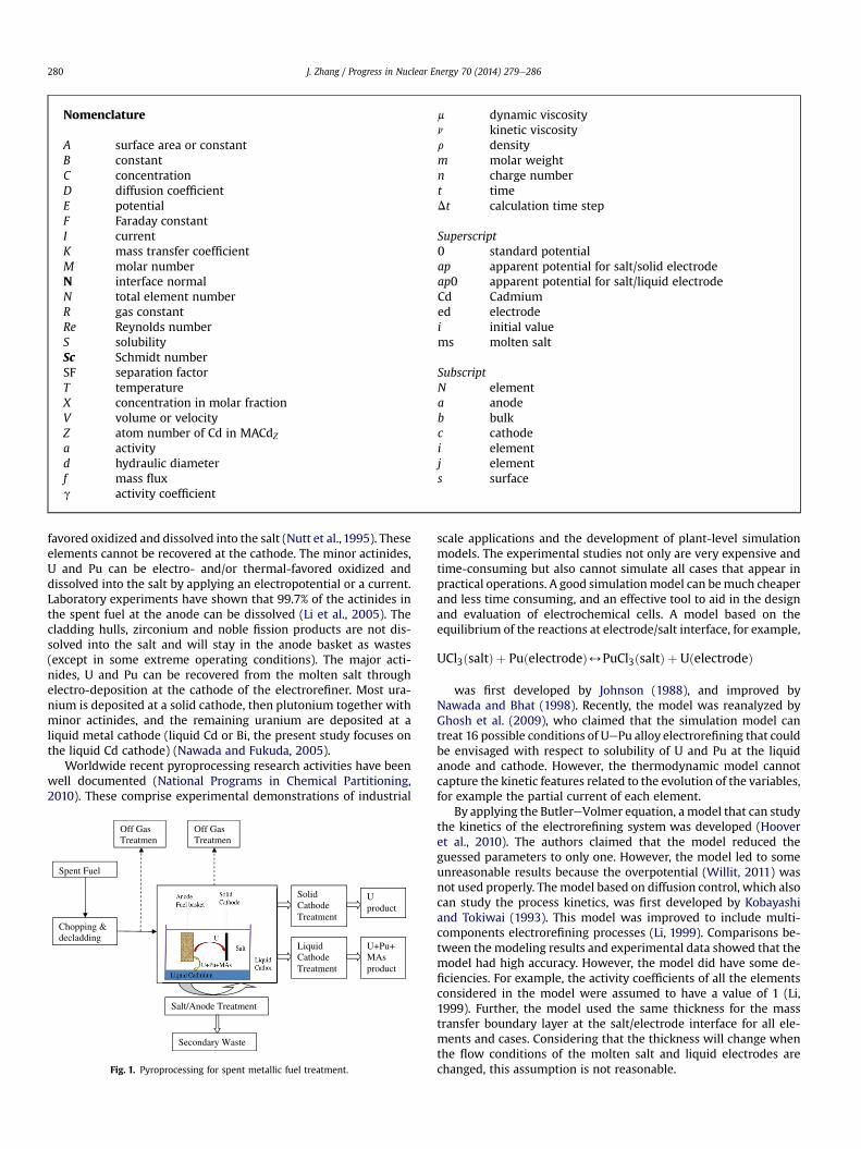
Pyroprocessing for the treatment of the spent metallic fuel isshown schematically in Fig. 1. The heart of pyroprocessing is theelectrorefiner where U, Pu and minor actinides are separated fromfission products. After chopping and de-cladding, the spent fuel isput into anode basket which is immersed into the molten salt. Thealkali, alkaline earth and rare earth fission products are thermal-
Nomenclature
A surface area or constantB constantC concentrationD diffusion coefficientE potentialF Faraday constantI currentK mass transfer coefficientM molar numberN interface normalN total element numberR gas constantRe Reynolds numberS solubilitySc Schmidt numberSF separation factorT temperatureX concentration in molar fractionV volume or velocityZ atom number of Cd in MACdZa activityd hydraulic diameterf mass fluxg activity coefficient
m dynamic viscosityn kinetic viscosityr densitym molar weightn charge numbert timeDt calculation time step
Superscript0 standard potentialap apparent potential for salt/solid electrodeap0 apparent potential for salt/liquid electrodeCd Cadmiumed electrodei initial valuems molten salt
SubscriptN elementa anodeb bulkc cathodei elementj elements surface
J. Zhang / Progress in Nuclear Energy 70 (2014) 279e286280
favored oxidized and dissolved into the salt (Nutt et al., 1995). Theseelements cannot be recovered at the cathode. The minor actinides,U and Pu can be electro- and/or thermal-favored oxidized anddissolved into the salt by applying an electropotential or a current.Laboratory experiments have shown that 99.7% of the actinides inthe spent fuel at the anode can be dissolved (Li et al., 2005). Thecladding hulls, zirconium and noble fission products are not dis-solved into the salt and will stay in the anode basket as wastes(except in some extreme operating conditions). The major acti-nides, U and Pu can be recovered from the molten salt throughelectro-deposition at the cathode of the electrorefiner. Most ura-nium is deposited at a solid cathode, then plutonium together withminor actinides, and the remaining uranium are deposited at aliquid metal cathode (liquid Cd or Bi, the present study focuses onthe liquid Cd cathode) (Nawada and Fukuda, 2005).
Worldwide recent pyroprocessing research activities have beenwell documented (National Programs in Chemical Partitioning,2010). These comprise experimental demonstrations of industrial
Spent Fuel
Chopping & decladding
Off Gas Treatmen
Salt/Anode Treatment
Secondary Waste
Off Gas Treatmen
Solid Cathode Treatment
Liquid Cathode Treatment
U product
U+Pu+MAs product
Fig. 1. Pyroprocessing for spent metallic fuel treatment.
scale applications and the development of plant-level simulationmodels. The experimental studies not only are very expensive andtime-consuming but also cannot simulate all cases that appear inpractical operations. A good simulationmodel can bemuch cheaperand less time consuming, and an effective tool to aid in the designand evaluation of electrochemical cells. A model based on theequilibrium of the reactions at electrode/salt interface, for example,
UCl3ðsaltÞ þ PuðelectrodeÞ4PuCl3ðsaltÞ þ UðelectrodeÞ
was first developed by Johnson (1988), and improved byNawada and Bhat (1998). Recently, the model was reanalyzed byGhosh et al. (2009), who claimed that the simulation model cantreat 16 possible conditions of UePu alloy electrorefining that couldbe envisaged with respect to solubility of U and Pu at the liquidanode and cathode. However, the thermodynamic model cannotcapture the kinetic features related to the evolution of the variables,for example the partial current of each element.
By applying the ButlereVolmer equation, a model that can studythe kinetics of the electrorefining system was developed (Hooveret al., 2010). The authors claimed that the model reduced theguessed parameters to only one. However, the model led to someunreasonable results because the overpotential (Willit, 2011) wasnot used properly. Themodel based on diffusion control, which alsocan study the process kinetics, was first developed by Kobayashiand Tokiwai (1993). This model was improved to include multi-components electrorefining processes (Li, 1999). Comparisons be-tween the modeling results and experimental data showed that themodel had high accuracy. However, the model did have some de-ficiencies. For example, the activity coefficients of all the elementsconsidered in the model were assumed to have a value of 1 (Li,1999). Further, the model used the same thickness for the masstransfer boundary layer at the salt/electrode interface for all ele-ments and cases. Considering that the thickness will change whenthe flow conditions of the molten salt and liquid electrodes arechanged, this assumption is not reasonable.
J. Zhang / Progress in Nuclear Energy 70 (2014) 279e286 281
The kinetic model developed here is still based on the diffusioncontrol assumption. However, the present model is more advancedthan previous available models. The present model can treat multi-component electrorefining and capture the kinetic features of theprocesses from liquid anodes to solid/liquid cathodes and from solidanodes to solid/liquid cathodes. Themodel can be applied to performparametric studies to show the evolution and distribution of theconcentration partial currents of each element in the system asfunctions of time and operating conditions. The effects of flow dy-namics and the activity coefficients of the elements at the electrodesand in themoltensalt are incorporated into themodel simulations.Bysolving the kinetic equations, the model has the capability to predictthe evolution of the process as a function of the operating time.
2. The Mathematic model
2.1. Apparent electro potentials
Electrorefining for pyroprocessing involves electrochemistry,chemistry and physics. As a whole, the process is a highly non-linear system. For modeling the system, the interfacial in-teractions at interfaces of electrodes and molten salt must be takeninto account. At electrode surfaces, species are thermal-favored orelectro-favored dissolve into or deposit from the liquid salt bath, forexample, U dissolves/deposits through the following reactions:
Uðanode;dissolutionÞ/U3þðsaltÞ þ 3e
U3þðsaltÞ þ 3e/Uðcathode;depositionÞThe total reaction is: UðanodeÞ/UðcathodeÞ, which indicates
that the molten salt is not involved. If the anode and the cathodeare in the same phase (liquid or solid), there is no potential dif-ference in the reaction. The potential difference between anode andcathode is created by the concentration distributions in the masstransfer boundary layer (concentration polarization) and theresistance of the molten salt. For other actinides, the reactions aresimilar. The electrode potential can be expressed by:
Ei ¼ E0i þ RTniF
ln
amsi;s
aedi;s
!(1)
where Ei ¼ electrode potential of the element i; E0i ¼ standardpotential of the element i; R ¼ gas constant; T ¼ temperature inKelvin; ni is the ion charge number of the element i;ams
i;s ¼ the ac-tivity of element i at the molten salt/electrode surface in themoltensalt side; and aedi;s ¼ the activity at the electrode side. The activitycan be expressed by ai ¼ giXi with gi the activity coefficient and Xithe concentration in atom fraction. Eq. (1) can be rewritten as:
Ei ¼ Eapi þ RTniF
lnXmsi;s
Xedi;s
(2)
where Eapi is the apparent standard potential and is expressed by:
Eapi ¼ E0i þ RTniF
lngmsi
gedi(3)
Eq. (3) can also be rewritten by:
Eapi ¼ Eap;0i � RTniF
lngedi (4)
where Eap;0i , which is the apparent potential in molten salt, isexpressed by:
Eap;0i ¼ E0i þ RTniF
lngmsi
For a solid electrode, the activity coefficient in the electrode isassumed to be 1 in the present model, then Eapi ¼ Eap;0i , while forliquid cadmium electrode,
Eapi ¼ Eap;0i � RTniF
lngCdi
where gCdi is the activity coefficient of element i in liquid cadmium.The potentials at the anode (Ea) and the cathode (Ec) are
calculated by:
Ea ¼ Ei;a ¼ Ej;a ¼ . ¼ EN;a;Ec ¼ Ei;c ¼ Ej;c ¼ . ¼ EN;c; (5)
Based on Eq. (5), the separation factor between two elements atthe salt/electrode interface is:
SFi;j ¼Xmsi;s
Xedi;s
Xedj;s
Xmsj;s
¼ Xmsj;s
Xedj;s
!ðnj�niÞ=ni
exp
�Eapj � Eapi
�njF
RT
!(6)
The separation factor defined in Eq. (6) is different from theprevious definition. In Eq. (6), the concentration at the interface isused instead of using bulk concentration as in previous mea-surements, for example, the value reported in Koyama et al.(1992).
2.2. Mass transfer and current
According to the Fick’s law, the molar flux of an element at themolten salt/electrode interface can be expressed by:
fi ¼ �DiAvCivN
(7)
where N is the normal of the molten salt/electrode interface, Di isthe diffusion coefficient of element i, A is the area of the interface,and Ci is the concentration in mol/m3. In the molten salt and liquidcadmium, the relationships between Ci and Xi are:
Cmsi ¼ Xms
i rms=mmsand CCdi ¼ XCd
i rCd=mCd (8)
where rms and rCd are the densities of the molten salt and liquidcadmium, respectively, and mms and mCd are the molar weights ofthe molten salt and the liquid cadmium.
Assuming that mass transfer is controlled by the transferthrough the boundary layer, Eq. (7) can be rewritten by using amass transfer coefficient, Ki. At the interfaces of the molten salt andthe liquid anode:
f msi;a ¼�AaKms
i;a
�Cmsi;b �Cms
i;s;a
�;f Cdi;a ¼�AaKCd
i;a
�CCdi;s;a�CCd
i;b
�f msi;a ¼ f Cdi;a ;
(9)
and at the interfaces of the molten salt and the liquid cathode:
f msi;c ¼ AcKms
i;c
�Cmsi;b �Cms
i;s;c
�; f Cdi;c ¼ AcKCd
i;c
�CCdi;s;c�CCd
i;b
�; f msi;c ¼ f Cdi;c ;
(10)
where subscripts c and a in Eqs. (9) and (10) represent the cathodeand the anode, respectively. At the interfaces of the molten salt andthe solid electrode:
J. Zhang / Progress in Nuclear Energy 70 (2014) 279e286282
f msi;a ¼ �AaKms
i;a Cmsi;b � Cms
i;s;a ; (11)
� �f msi;c ¼ AcKms
i;c
�Cmsi;b � Cms
i;s;c
�; (12)
The current by transport of ions of species i at the anode (Ii,a) andthe cathode (Ii,c) can be calculated by:
Ii;a ¼ niFfmsi;a and Ii;c ¼ niFf
msi;c ; (13)
The total currents at the anode and cathode and their relation-ship are expressed by:
Ia ¼XNi
Ii;a; Ic ¼XNi
Ii;c; Ia ¼ Ic ¼ I; (14)
where I is the applied current.
2.3. Kinetic equations
The bulk concentration element i in the molten salt obeys akinetic equation:
dVmsCmsi;b
dt¼ Ii;a � Ii;c
niF(15)
where Vms is the volume of the molten salt in the system.Considering the charge neutrality in the molten salt:
XNi
nidCmsi
dt¼ 0 (16)
The amount of species i at the anode and cathode can be thenexpressed by:
dMi;a
dt¼ � Ii;a
niF;dMi;c
dt¼ Ii;c
niF(17)
where M is molar number. For the liquid cadmium electrode, thesurface area is constant, while for the solid electrode, the surfacearea will be changed by material dissolution and deposition.
For liquid cadmium electrode, if none of the concentration of theactinides considered exceeds its solubility limit, the bulk concen-tration can be calculated by:
VCda dCCd
i;b;a
dt¼ � Ii;a
niF;VCdc dCCd
i;b;c
dt¼ Ii;c
niF(18)
where VCda and VCd
c are the volume of the liquid anode and cathode,respectively. So far, it has been recognized that U does not formstable metallic compounds with cadmium, but actinides such as Puand Am will form metallic compounds that can deposit if theirconcentration exceeds their solubility limits in liquid cadmium(Ahluwalia and Hua, 2002). For example, Pu can result in the for-mation of PuCd6 through the following reaction:
PuðsolidÞ þ 6CdðliquidÞ/PuCd6ðsolidÞThe deposition of PuCd6 changes the mass and volume of the
liquid cadmium, and the concentrations of the other actinides.Therefore, volume changes during operation must be included inthe model. The volume change by the above reaction at the liquidcathode can be expressed by:
dVCdc
dt¼ IPu;c6mCd
nPuF�6mCdSCdPu � rCd
� (19)
While at the liquid anode, the volume change follows:
dVCda
dt¼ � IPu;a6mCd
nPuF�6mCdSCdPu � rCd
� (20)
where SCdPu is the solubility of Pu in liquid cadmium. If more than oneelement can form the metallic compound precipitates, MACdz, theinteraction between the precipitations must be considered and:
dVCdc
dt¼
mCd PkiIi;cZiniF
rCd �mCdPk
i SCdi Zi
(21)
Replacing Ii;c by �Ii;a, in Eq. (21), the volume change rate at theanode by dissolution of metallic compounds can be calculated.
For an element that is in its saturated state, the concentration inthe liquid cadmium is uniform and equals its solubility:
CCdi;b;a ¼ SCdi;a ; CCd
i;b;c ¼ SCdi;c (22)
These concentrations do not vary with time. For an elementwith a concentration less than its solubility, the bulk concentrationin the liquid cathode can be calculated by:
CCdi;b;a ¼ Mi;a
VCda
; CCdi;b;c ¼ Mi;c
VCdc
(23)
These concentrations vary with time because the amount ofelement i at the electrode and the electrode volume are bothfunctions of time.
2.4. Mass coefficient
The mass transfer coefficient Ki depends on the flow conditionsand the properties of the fluid. Many correlations for Ki in a tur-bulent flow have been summarized by Zhang and Li (2003). For thepresent model, we selected the correlation by Berger and Hau(1977):
Ki ¼ 0:0165n�0:530D0:670i V0:860d�140 (24)
where n is the kinetic viscosity of the fluid (molten salt or liquidcadmium in the present model), Di is the diffusion coefficient ofelement i in the fluid, V is the flow velocity and d is the hydraulicdiameter. It has been found that this correlation agrees well withtheoretical prediction (Zhang and Li, 2003). Eq. (24) can berewritten as:
Ki ¼ 0:0165Re0:860Sc0:33Di
d(25)
where Re ¼ Vd=n is Reynolds number and Sc ¼ n=Di is Schmidtnumber. Substituting Eq. (24) or 25 into Eqs. (9)e(12), one findsthat the partial current of each element depends on it flow condi-tions. Therefore, the present model can be applied to study effectsof flow velocity and the liquid properties on the performance of theelectrorefining.
3. Simulation model stream
If the operating conditions are given, the partial current of eachelement, the electropotential and the distribution of elements
J. Zhang / Progress in Nuclear Energy 70 (2014) 279e286 283
betweenmolten salt and electrode can be calculated by Eqs. (2) and(4), coupling with the kinetic Eqs. (17), (18) and (21).
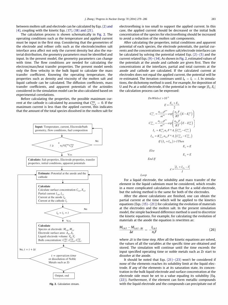
The calculation process is shown schematically in Fig. 2. Theoperating conditions such as the temperature and applied currentmust be input in the first step. Considering that the geometries ofthe electrode and refiner cells such as the electrode/molten saltinterface area affect not only the current density but also the ma-terial distribution, the geometry parameters must be identified andinput. In the present model, the geometry parameters can changewith time. The flow conditions are needed for calculating theelectron/mass/heat transfer properties. The present model needsonly the flow velocity in the bulk liquid to calculate the masstransfer coefficient. Knowing the operating temperature, theproperties such as density and viscosity of the molten salt andliquid cathode can be calculated. The diffusion coefficients, masstransfer coefficients, and apparent potentials of the actinidesconsidered in the simulation model can be also calculated based onexperimental correlations.
Before calculating the properties, the possible maximum cur-rent at the cathode is calculated by assuming that Cms
i;c;s ¼ 0. If themaximum current is less than the applied current, this indicatesthat the amount of the total species dissolved in the molten salt for
Input: Temperature, current, Electrode/bath geometry, flow conditions, fuel composition
Estimate: Potential at the anode and the cathode
CalculateCalculate surface concentration Partial current Current at the anode Current at the cathode
Yes
Yes
or dissolution of Noble Metals such as Zr
Output, end
Yes
Calculate: Salt properties, Electrode properties, transfer properties, initial conditions, apparent potentials
CalculateSpecies at electrode: Electrode surface area: Liquid electrode volume: Bulk concentration:
Fig. 2. Calculation stream.
electrorefining is too small to support the applied current. In thiscase, the applied current should be decreased or the initial bulkconcentration of the species for electrorefining should be increasedto avoid a reduction of the molten salt components.
After calculating the properties, initial conditions and apparentpotential of each species, the electrode potentials, the partial cur-rents and the concentrations at molten salt/electrode interfaces canbe calculated by solving the potential related Eqs. (2)e(5) and thecurrent related Eqs. (9)e(14). As shown in Fig. 2, estimated values ofthe potentials at the anode and cathode are given first. Then theconcentrations at the interfaces, partial and total currents at theanode and cathode are calculated. If the calculated current atelectrodes does not equal the applied current, the potential will bere-estimated. The iteration continues until Ia ¼ Ic ¼ I. In simula-tions, the dichotomymethod is used. For example, for deposition ofU and Pu at a solid electrode, if the potential is in the range ½ES; EL�the calculation process can be expressed:
6 10DoWhileε −>
2L SE E
E+=
( ),,
msU C pasm U
UsU ms
a n FC exp E E
m RT
ρ ⎛ ⎞= −⎜ ⎟⎝ ⎠
( ),,
msU C pasm Pu
uPsuP ms
a n FC exp E E
m RT
ρ ⎛ ⎞= −⎜ ⎟⎝ ⎠( ), , ,*ms ms ms
U U C U c U b U sI K n F A C C= −
( ),,, *ms ms msPu Pu C Pu c Pu b Pu sI K n F A C C= −
( )U PuIf I I I Then+ >
LE E=Else
SE E=End If
–U PuI I I
Iε
+=
Loop
For a liquid electrode, the solubility and mass transfer of theelement in the liquid cadmium must be considered, which resultsin a more complicated calculation than that for a solid electrode,but the solving method is the same for both of the electrodes.
After the above calculations are finished, one can obtain thepartial current at the time which will be applied to the kineticsequations (Eqs. (15)e(21)) for calculating the evolution of materialsat the electrodes and the molten salt. In the present simulationmodel, the simple backward difference method is used to discretizethe kinetic equations. For example, for calculating the evolution ofmaterials at the anode the equation is rewritten as:
Mi;a;t �Mi;a;t�Dt
Dt¼ �Ii;a;t
niF(26)
where Dt is the time step. After all the kinetic equations are solved,the values of all the variables at the specific time are obtained andstored. The simulation will continue until the time exceeds theinput specified operating time or noble metals such as Zr start todissolve at the anode.
It should be noted that Eqs. (21)e(23) won’t be considered ifnone of the elements reaches its solubility limit at the liquid elec-trode. If any of the elements is at its saturation state, its concen-tration in the bulk liquid electrode and surface concentration at theelectrode side must be set to a value equaling its solubility (Eq.(22)). Furthermore, if the element can form metallic compoundswith the liquid electrode and the compounds can precipitate out of
(a)0
50
100
150
200
250
0 10 20 30 40 50 60
Dep
ositi
on a
t sol
id c
atho
de
(g)
Time (hour)
0.8
1
1.2
in th
e (w
t%)
Pu
U
J. Zhang / Progress in Nuclear Energy 70 (2014) 279e286284
the liquid, Eq. (21) must be solved, and the bulk concentrations ofother elements which do not reach their solubility limits should becalculated by Eq. (23), which implicitly depends on the timebecause of the change of the liquid electrode volume.
4. Model validation and discussion
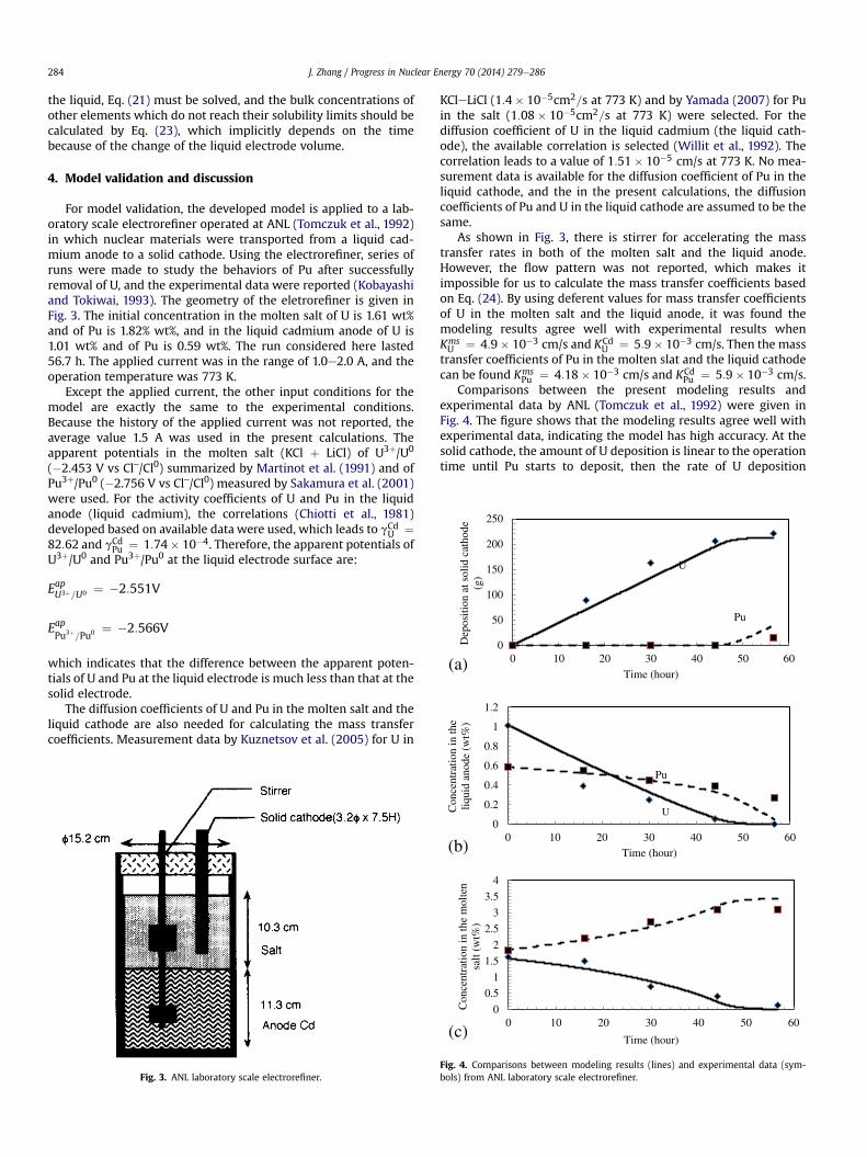
For model validation, the developed model is applied to a lab-oratory scale electrorefiner operated at ANL (Tomczuk et al., 1992)in which nuclear materials were transported from a liquid cad-mium anode to a solid cathode. Using the electrorefiner, series ofruns were made to study the behaviors of Pu after successfullyremoval of U, and the experimental data were reported (Kobayashiand Tokiwai, 1993). The geometry of the eletrorefiner is given inFig. 3. The initial concentration in the molten salt of U is 1.61 wt%and of Pu is 1.82% wt%, and in the liquid cadmium anode of U is1.01 wt% and of Pu is 0.59 wt%. The run considered here lasted56.7 h. The applied current was in the range of 1.0e2.0 A, and theoperation temperature was 773 K.
Except the applied current, the other input conditions for themodel are exactly the same to the experimental conditions.Because the history of the applied current was not reported, theaverage value 1.5 A was used in the present calculations. Theapparent potentials in the molten salt (KCl þ LiCl) of U3þ/U0
(�2.453 V vs Cl‒/Cl0) summarized by Martinot et al. (1991) and ofPu3þ/Pu0 (�2.756 V vs Cl‒/Cl0) measured by Sakamura et al. (2001)were used. For the activity coefficients of U and Pu in the liquidanode (liquid cadmium), the correlations (Chiotti et al., 1981)developed based on available data were used, which leads to gCd
U ¼82:62 and gCdPu ¼ 1:74� 10�4. Therefore, the apparent potentials ofU3þ/U0 and Pu3þ/Pu0 at the liquid electrode surface are:
EapU3þ=U0 ¼ �2:551V
EapPu3þ=Pu0 ¼ �2:566V
which indicates that the difference between the apparent poten-tials of U and Pu at the liquid electrode is much less than that at thesolid electrode.
The diffusion coefficients of U and Pu in the molten salt and theliquid cathode are also needed for calculating the mass transfercoefficients. Measurement data by Kuznetsov et al. (2005) for U in
Fig. 3. ANL laboratory scale electrorefiner.
KCleLiCl (1:4� 10�5cm2=s at 773 K) and by Yamada (2007) for Puin the salt (1:08� 10�5cm2=s at 773 K) were selected. For thediffusion coefficient of U in the liquid cadmium (the liquid cath-ode), the available correlation is selected (Willit et al., 1992). Thecorrelation leads to a value of 1:51� 10�5 cm/s at 773 K. No mea-surement data is available for the diffusion coefficient of Pu in theliquid cathode, and the in the present calculations, the diffusioncoefficients of Pu and U in the liquid cathode are assumed to be thesame.
As shown in Fig. 3, there is stirrer for accelerating the masstransfer rates in both of the molten salt and the liquid anode.However, the flow pattern was not reported, which makes itimpossible for us to calculate the mass transfer coefficients basedon Eq. (24). By using deferent values for mass transfer coefficientsof U in the molten salt and the liquid anode, it was found themodeling results agree well with experimental results whenKmsU ¼ 4:9� 10�3 cm/s and KCd
U ¼ 5:9� 10�3 cm/s. Then the masstransfer coefficients of Pu in the molten slat and the liquid cathodecan be found Kms
Pu ¼ 4:18� 10�3 cm/s and KCdPu ¼ 5:9� 10�3 cm/s.
Comparisons between the present modeling results andexperimental data by ANL (Tomczuk et al., 1992) were given inFig. 4. The figure shows that the modeling results agree well withexperimental data, indicating the model has high accuracy. At thesolid cathode, the amount of U deposition is linear to the operationtime until Pu starts to deposit, then the rate of U deposition
(b)
(c)
0
0.2
0.4
0.6
0 10 20 30 40 50 60
Con
cent
ratio
nliq
uid
anod
e
Time (hour)
U
Pu
0
0.5
1
1.5
2
2.5
3
3.5
4
0 10 20 30 40 50 60
Con
cent
ratio
n in
the
mol
ten
salt
(wt%
)
Time (hour)
Fig. 4. Comparisons between modeling results (lines) and experimental data (sym-bols) from ANL laboratory scale electrorefiner.
Cel
l Vol
tage
(V
)
Time (hour)
Fig. 5. Cell voltage (Symbols: experimental measurement, Line: modeling results).
J. Zhang / Progress in Nuclear Energy 70 (2014) 279e286 285
becomes smaller as shown in Fig. 4a. At the liquid anode, both ofthe concentrations of U and Pu decrease with operation time.However, the decrease trends are very different. The decrease rateof the U concentration is large at the beginning and becomessmaller with time, while the decrease rate of the Pu concentrationis small at the beginning and becomes larger with time as shown in
Fig. 6. Effects of mass the transfer coeffici
Fig. 4b. In the molten salt, the Pu concentration increases with timeand the increase rate is significantly reduced when Pu starts todeposit at the solid cathode. The U concentration decreases, alsothere is an inflection point after which the decrease rate is reducedas shown in Fig. 4a.
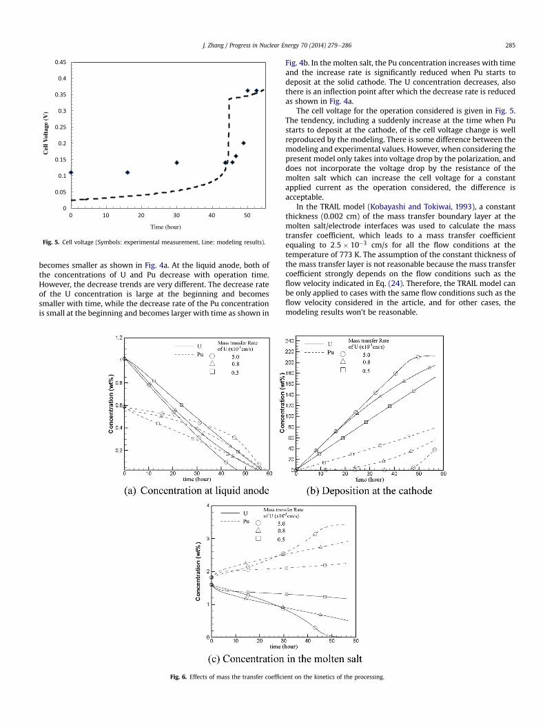
The cell voltage for the operation considered is given in Fig. 5.The tendency, including a suddenly increase at the time when Pustarts to deposit at the cathode, of the cell voltage change is wellreproduced by the modeling. There is some difference between themodeling and experimental values. However, when considering thepresent model only takes into voltage drop by the polarization, anddoes not incorporate the voltage drop by the resistance of themolten salt which can increase the cell voltage for a constantapplied current as the operation considered, the difference isacceptable.
In the TRAIL model (Kobayashi and Tokiwai, 1993), a constantthickness (0.002 cm) of the mass transfer boundary layer at themolten salt/electrode interfaces was used to calculate the masstransfer coefficient, which leads to a mass transfer coefficientequaling to 2:5� 10�3 cm/s for all the flow conditions at thetemperature of 773 K. The assumption of the constant thickness ofthe mass transfer layer is not reasonable because the mass transfercoefficient strongly depends on the flow conditions such as theflow velocity indicated in Eq. (24). Therefore, the TRAIL model canbe only applied to cases with the same flow conditions such as theflow velocity considered in the article, and for other cases, themodeling results won’t be reasonable.
ent on the kinetics of the processing.
J. Zhang / Progress in Nuclear Energy 70 (2014) 279e286286
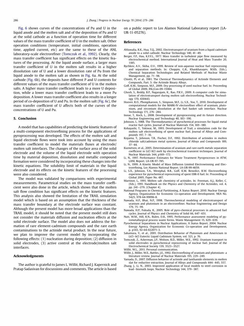
Fig. 6 shows curves of the concentrations of Pu and U in theliquid anode and the molten salt and of the deposition of Pu and Uat the solid cathode as a function of operation time for differentvalues of the mass transfer coefficient of U in the molten salt. Otheroperation conditions (temperature, initial conditions, operationtime, applied current, etc) are the same to these of the ANLlaboratory-scale electrorefiner (Tomczuk et al., 1992). Clearly, themass transfer coefficient has significant effects on the kinetic fea-tures of the processing. At the liquid anode surface, a larger masstransfer coefficient of U in the molten salt results in a higherdissolution rate of U and a lower dissolution rate of Pu from theliquid anode to the molten salt as shown in Fig. 6a. At the solidcathode (Fig. 6b), the deposits have different P and U contents fordifferent values of the mass transfer coefficient of U in the moltensalts. A higher mass transfer coefficient leads to a more U deposi-tion, while a lower mass transfer coefficient leads to a more Pudeposition. A lower mass transfer coefficient also results in a longerperiod of co-deposition of U and Pu. In the molten salt (Fig. 6c), themass transfer coefficient of U affects both of the curves of theconcentrations of U and Pu.
5. Conclusion
Amodel that has capabilities of predicting the kinetic features ofa multi-component electrorefining process for the applications ofpyroprocessing was developed. The effects of the molten salt andliquid electrode flows were took into account by using the masstransfer coefficient to model the materials fluxes at electrode/molten salt interfaces. The changes of the surface area of the solidelectrode and the volume of the liquid electrode with operationtime by material deposition, dissolution and metallic compoundformationwere considered by incorporating these changes into thekinetic equations. The solubility limit of materials in the liquidelectrode and its effects on the kinetic features of the processingwere also considered.
The model was validated by comparisons with experimentalmeasurements. Parametrical studies on the mass transfer coeffi-cient were also done in the article, which shows that the moltensalt flow condition has significant effects on the kinetic features.This analysis also showed the limitation of the TRAIL simulationmodel which is based on an assumption that the thickness of themass transfer boundary at the electrode surface was constant.Although the present model has more broad applications than theTRAIL model, it should be noted that the present model still doesnot consider the materials diffusion and nucleation effects at thesolid electrode surface. The model also does not address the for-mation of rare element-cadmium compounds and the rare earthcontaminations to the actinide metal product. In the near future,we plan to improve the current model by incorporating thefollowing effects: (1) nucleation during deposition; (2) diffusion insolid electrodes, (3) active control at the electrode/molten saltinterfaces.
Acknowledgments
The author is grateful to James L. Willit, Richard J. Kapernick andPratap Sadasivan for discussions and comments. The article is based
on a public report to Los Alamos National Laboratory report (LA-UR-11-05276).
References
Ahluwalia, R.K., Hua, T.Q., 2002. Electrotransport of uranium from a liquid cadmiumanode to a solid cathode. Nuclear Technology 140, 41e49.
Berger, F.P., Hau, K.F.F.L., 1977. Mass transfer in turbulent pipe flow measured byelectrochemical method. International Journal of Heat and Mass Transfer 20,1185.
Bychkov, A.V., Skiba, O.V., 1999. Review of non-aqueous nuclear fuel reprocessingand separation methods. In: Choppin, G.R., Khankhasayev, M.Kh. (Eds.),Chemical Separation Technologies and Related Methods of Nuclear WasteManagement, pp. 71e98.
Chiotti, Pl, et al., 1981. The Chemical Thermodynamics of Actinide Elements andCompunds, Part. 5: the Actinide Binary Alloys.
Goff, K.M., Simpson, M.F., 2009. Dry processing of used nuclear fuel. In: Proceedingof Global 2009, INL/Con-09-15984.
Ghosh, S., Reddy, B.P., Nagarajam, K., Rao, P.R.V., 2009. A computer code for simu-lation of electrotransport during molten salt electrorefining. Nuclear Technol-ogy 170, 430443.
Hoover, R.O., Phongikaroon, S., Simpson, M.F., Li, S.X., Yoo, T., 2010. Development ofcomputational models for the MARK-IV electorefiner effect of uranium, pluto-nium, and zirconium dissolution at the fuel basket salt interface. NuclearTechnology 171, 276e284.
Inoue, T., Koch, L., 2008. Development of pyroprocessing and its future direction.Nuclear Engineering and Technology 40, 183e190.
Johnson, I., 1988. The Thermodynamics of pyrochemical processes for liquid metalreactor fuel cycles. Journal of Nuclear Materials 154, 169e180.
Kobayashi, T., Tokiwai, M., 1993. Development of Trail, a simulation code for themolten salt electrorefining of spent nuclear fuel. Journal of Alloys and Com-pounds 197, 7e16.
Koyama, T., Johnson, T.R., Fischer, D.F., 1992. Distribution of actinides in moltenchloride salt/cadmium metal systems. Journal of Alloys and Compounds 189,37e44.
Kuznetsov, et al., 2005. Determination of uranium and rare earth metals separationcoefficient in LiCl KCl melt by electrochemical transient techniques. Journal ofNuclear Materials 344, p169e172.
Li, N., 1997. Performance Estimates for Waste Treatment Pyroprocesses in ATW,LANL Report. LA-UR-97-785.
Li, N., 1999. A Kinetic Model of Mass Diffusion Limited Electrowinning and Elec-trorefining, Los Alamos National Report. LA-UR-99-4659.
Li, S.X., Johnson, T.A., Westphal, B.R., Goff, K.M, Benedict, R.W. Electrorefiningexperience for pyrochemical reprocessing of spent EBR-II fuel. In: Proceeding ofGlobal 2005, Paper No. 487.
Martinot, L., 1991. Molten salt chemistry of actinides. In: Freeman, A.J., Keller, C.(Eds.), 1991. Handbook on the Physics and Chemistry of the Actinides, vol. 4,pp. 241e279. (Chapter 4).
National Programs in Chemical Partitioning, A Status Report, 2010. Nuclear EnergyAgency, Organization for Economic Co-operation and Development. NEA No.5425, 978-64-99096-8.
Nawada, H.P., Bhat, N.P., 1998. Thermochemical modeling of electrotransport ofuranium and plutonium in an electrorefiner. Nuclear Engineering and Design179, 75e99.
Nawada, H.P., Fukuda, K., 2005. Role of pyro-chemical processes in advanced fuelcycles. Journal of Physics and Chemistry of Solid 66, 647e651.
Nutt, W.M., Hill, R.N., Bulen, D.B., 1995. Performance assessment modeling of py-rometallurgical process waste forms. Waste Management 15, 629e639.
Pyrochemical Separations in Nuclear Applications, A Status Report, 2004. NuclearEnergy Agency, Organization for Economic Co-operation and Development,p. p143, 92-64-022071-3.
Sakamura, Y., et al., 2001. Distribution Behavior of Plutonium and Americium inLiClekCl Eutectic Liquid Cadmium System, vol. 321, p. 76.
Tomczuk, Z., Ackerman, J.P., Wolson, R.D., Miller, W.E., 1992. Uranium transport tosolid electrodes in pyrochemical reprocessing of nuclear fuel. Journal of theElectrochemical Society 139, 3523e3527.
Willit, W.L., 2011. Personal communication.Willit, J., Miller, W.E., Battles, J.E., 1992. Electrorefining of uranium and plutonium- a
literature review. Journal of Nuclear Materials 195, 229e249.Yamada, D., 2007. Diffusion behavior of actinide and lanthanide elements in molten
slat for reductive extraction. Journal of Alloys and Compounds 444e445, 557.Zhang, J., Li, N., 2003. Improved application of local models to steel corrosion in
leadebismuth loops. Nuclear Technology 144, 379e387.