jyoti international
DESCRIPTION
hiTRANSCRIPT
Training: 6 weeks
Training Report File
Of
Jyoti International (Electrical Division)
Submitted in the partial fulfillment of the requirement for the
award of
Diploma of Technology
In
Submitted to: Submitted ByEr. Amit Kumar Sharma Rishi Kumar
Er. Priyanka Chaudhary 13632E.E
RIMT Polytechnic College 1
RIMT POLYTECHNIC COLLEGE, MANDI GOVINDHGARH
CONTENTS
S. No. Topic Page No.
1 Acknowledgement 3
2 Company Profile 4-7
3 Products 8-8
4 Distribution Transformers 9-16
5 Magnetic Oil Level Gauge 17-20
6 Voltage Stablizers 21-27
7 Control Panel 28-37
8 References 38
RIMT Polytechnic College 2
ACKNOWLEDGEMENT
Any endeavor cannot lead to success unless and until a proper platform is
provided for the same. This is the reason I find myself very fortunate to have
undergone my industrial training in Jyoti International (Electrical
Division). The persons of all departments have extended a warm and helping
hand.
First of all I would like to thank Er. Amit Kumar Sharma & Er. Priyanka
Chaudhary for his valuable guidance & encouragement as a teacher and a
friend throughout my training period.
I am also equally thankful to Er. V.S. Bhatt (Manager) for their kind
guidance. They guided us in a very efficient manner and always invited us
with our problems.
My deepest recognition goes to my beloved parents, who are helping me in
any imaginable way to achieve my objectives and fulfill my dreams.
RIMT Polytechnic College 3

COMPANY PROFILE
JYOTI INTERNATIONAL (Electrical-Division) an ISO 9001:2000
certified organization is a multi product and services organization. We are
in manufacturing, testing, supplying, erection and commissioning of
Power and Distribution Transformers, complete sub-stations on turnkey
projects with distinction and credibility over the past 20 years. Owing to
adherence to international Quality norms and prompt customer services.
JYOTI INTERNATIONAL (Electrical-Division) has an excellent brand
image and is an ISO 9001:2000 certified Company.
Following a "Total Customer Satisfaction" approach, we reinforce our
commitment to offer total quality products. Our customer service
representatives, sales team, and engineering group are available and
always ready to attend the customer, resolve issues, and provide insight
into requirements for custom designs. From acknowledging inquiries to
following up on customer feedback or orders, we maintain open lines of
communication to serve our diverse clients.
RIMT Polytechnic College 4

Infrastructure
Sprawling over a large area, the state of the art infrastructure is the most
credited feature of our organization. It houses our proficient team and
accommodates technically advanced machinery. Moreover, our
infrastructure assists in proper production of goods in bulk quantities that
too within stipulated time frame.
Team
Our business endeavors are supported by a proficient team which is well
acknowledged with the production, packaging, and distribution processes.
Our team works with proper co-coordination with each other and thus
serves the best in terms of quality, packaging, and distribution.
Network
Having an intense base of network in every nook and corner of the India
enables us to maintain the demand and supply chain efficiently. It helps us
to procure high quality raw materials and assists in the distribution of
finished products in the market With the help of widespread networking,
we have connected ourselves with the most reputed clients of Indian
market.
Our Mission
To provide environment-friendly atmosphere around the allocation with
RIMT Polytechnic College 5
less disturbance to the nature.
Nurture a culture of dynamism and learning that provides all employees
with an opportunity for professional as well as personal growth.
As an ISO 9001:2000 accredited organization, we are
committed to build and sustain ourselves as
anorganization for transformer, Servo & Control Panel
manufacturing, where quality shall be the hallmark of
every action. We have set up a complete quality management system to
offer the best customer satisfaction. Nothing has a higher priority than
quality in engineering, in manufacturing, in sales and in services. The
JYOTI INTERNATIONAL (Electrical-Division) total quality program is
based on the philosophy of prevention, and not just on the detection and
correction of problems after the occur. JYOTI INTERNATIONAL
(Electrical-Division) is a quality conscious company. Therefore, we
provide high importance to qualitative aspects, whether it is about
products' quality or about services. In order to bestow premium quality
products, we stringently adhere to quality management system right from
product procurement till supply at client's end.
Clientele
JYOTI INTERNATIONAL (Electrical-Division) is supplying products to
the Customers according to their needs & Specification with best of their
quality.
Why Us
RIMT Polytechnic College 6

Some of the competitive advantages that place JYOTI INTERNATIONAL
(Electrical-Division) ahead in the industry are:
Total customer satisfaction
Professional services to the customers
Import standard quality
On-time delivery
Extensive range of products
Capability to meet bulk order
RIMT Polytechnic College 7
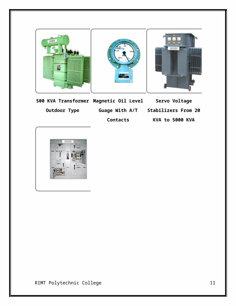
PRODUCTS
500 KVA Transformer
Outdoor Type
Magnetic Oil Level Guage
With A/T Contacts
Servo Voltage Stabilizers
From 20 KVA to 5000 KVA
RIMT Polytechnic College 8
DISTRIBUTION TRANSFORMER
A distribution transformer is a transformer that provides the
final voltagetransformation in the electric power distribution system,
stepping down the voltage used in the distribution lines to the level used by
the customer. The invention of a practical efficient transformer made AC
power distribution feasible; a system using distribution transformers was
demonstrated as early as 1882.
If mounted on a utility pole, they are called pole-mount transformers. If
the distribution lines are located at ground level or underground, distribution
transformers are mounted on concrete pads and locked in steel cases, thus
known as pad-mount transformers.
Distribution transformers normally have ratings less than 200
kVA, although some national standards can describe units up to 5000 kVA
as distribution transformers. Since distribution transformers are energized
for 24 hours a day (even when they don't carry any load), reducing iron
losses has an important role in their design. As they usually don't operate at
full load, they are designed to have maximum efficiency at lower loads. To
have a better efficiency, voltage regulation in these transformers should be
kept to a minimum. Hence they are designed to have small leakage
reactance.
Classification
RIMT Polytechnic College 9

Distribution transformers are classified into different categories based on
certain factors such as:
Mounting location – pole, pad, underground vault
Type of insulation – liquid-immersed or dry-type
Number of Phases – single-phase or three-phase
Voltage class
Basic impulse insulation level (BIL).
Use
Distribution transformers are normally located at a service drop, where wires
run from a utility pole or underground power lines to a customer's premises.
They are often used for the power supply of facilities outside settlements,
such as isolated houses, farmyards or pumping stations at voltages below 30
kV. Another application is the power supply of the overhead wire
of railways electrified with AC. In this case single phase distribution
transformers are used.
The number of customers fed by a single distribution transformer varies
depending on the number of customers in an area. Several homes may be fed
off a single transformer in urban areas; rural distribution may require one
transformer per customer. A large commercial or industrial complex will
have multiple distribution transformers. Padmount transformers are used in
urban areas and neighborhoods where the primary distribution lines run
underground. Many large buildings have electric service provided at primary
distribution voltage. These buildings have customer-owned transformers in
the basement for step-down purposes. [4] In a secondary network system as
RIMT Polytechnic College 10
used in urban areas, many distribution transformers may be connected in
parallel, each equipped with its own network protector circuit breaker to
isolate it from the secondary network in case of a fault.
Distribution transformers are also found in the power collector networks
of wind farms, where they step up power from each wind turbine to connect
to a substation that may be several miles (kilometres) distant.
Construction
Distribution transformers are made using a core made from laminations of
sheet steelstacked and either glued together with resin or banded together
with steel straps. Where large numbers of transformers are made to standard
designs, a wound C-shaped core is economic to manufacture. A steel strip is
wrapped around a former, pressed into shape and then cut into two C-shaped
halves, which are re-assembled on the copper windings. [6]
The primary coils are wound from enamel coated copper or aluminum wire
and the high current, low voltage secondaries are wound using a thick ribbon
of aluminum or copper. The windings are insulated with resin-impregnated
paper. The entire assembly is baked to cure the resin and then submerged in
a powder coated steel tank which is then filled withtransformer oil (or other
insulating liquid), which is inert and non-conductive. The transformer oil
cools and insulates the windings, and protects the transformer winding from
moisture, which will float on the surface of the oil. The tank is temporarily
depressurized to remove any remaining moisture that would cause arcing
and is sealed against the weather with a gasket at the top.
RIMT Polytechnic College 11
Formerly, distribution transformers for indoor use would be filled with
a polychlorinated biphenyl (PCB) liquid. Because these liquids persist in the
environment and have adverse effects on animals, they have been banned.
Other fire-resistant liquids such as silicones are used where a liquid-filled
transformer must be used indoors. Certain vegetable oils have been applied
as transformer oil; these have the advantage of a high fire point and are
completely biodegradable in the environment.
Pole-mounted transformers often include accessories such as surge arresters
or protective fuse links. A self-protected transformer includes an internal
fuse and surge arrester; other transformers have these components mounted
separately outside the tank. [8] Pole-mounted transformers may have lugs
allowing direct mounting to a pole, or may be mounted on crossarms bolted
to the pole. Aerial transformers, larger than around 75 kVA, may be
mounted on a platform supported by one or more poles. A three-phase
service may use three identical transformers, one per phase.
Transformers designed for below-grade installation can be designed for
periodic submersion in water.
Distribution transformers may include an off-load tap changer to allow slight
adjustment of the ratio between primary and secondary voltage, to bring the
customer voltage within the desired range on long or heavily loaded lines.
Pad-mounted transformers have secure locked and bolted grounded metal
enclosures to discourage unauthorized access to live internal parts. The
enclosure may also include fuses, isolating switches, load-break bushings,
and other accessories as described in technical standards. Pad-mounted
transformers for distribution systems typically range from around 100 to
2000 kVA, although some larger units are also used.
RIMT Polytechnic College 12
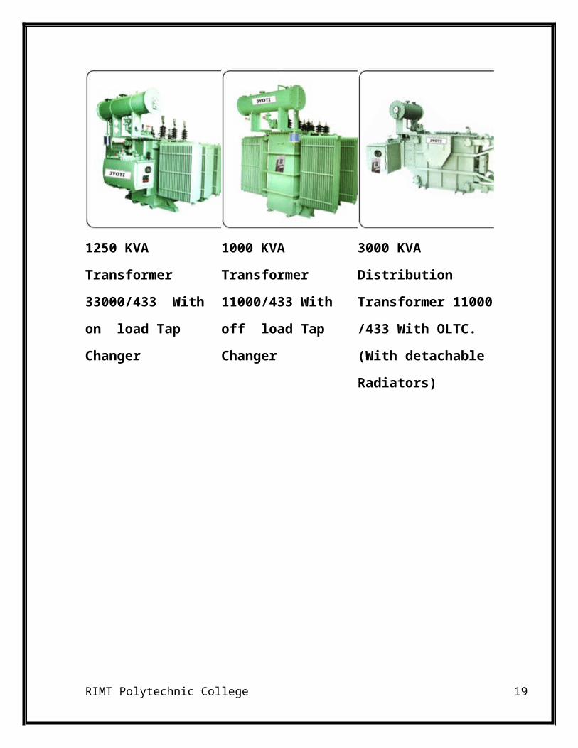
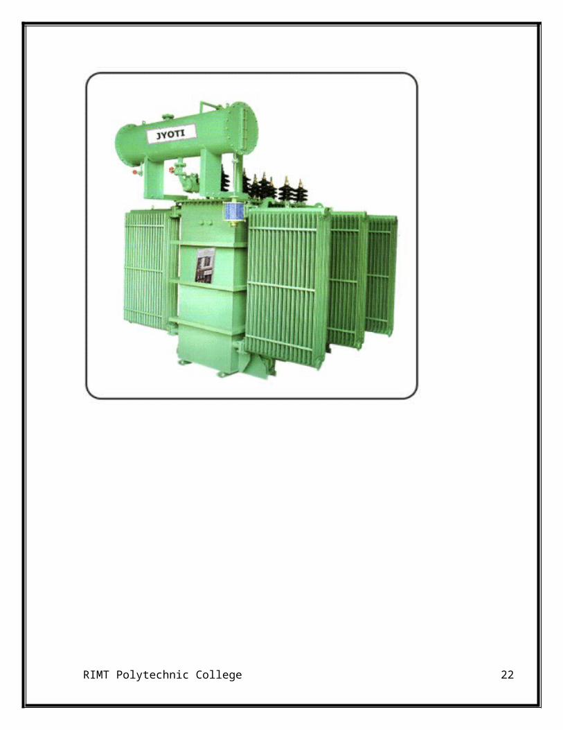
DISTRIBUTION TRANSFORMERS
1250 KVA Transformer
33000/433 With on
load Tap Changer
1000 KVA Transformer
11000/433 With off
load Tap Changer
3000 KVA Distribution
Transformer 11000/433
With OLTC. (With
detachable Radiators)
RIMT Polytechnic College 13
1250 KVA Transformer 33000/433 With on load Tap Changer
RIMT Polytechnic College 14
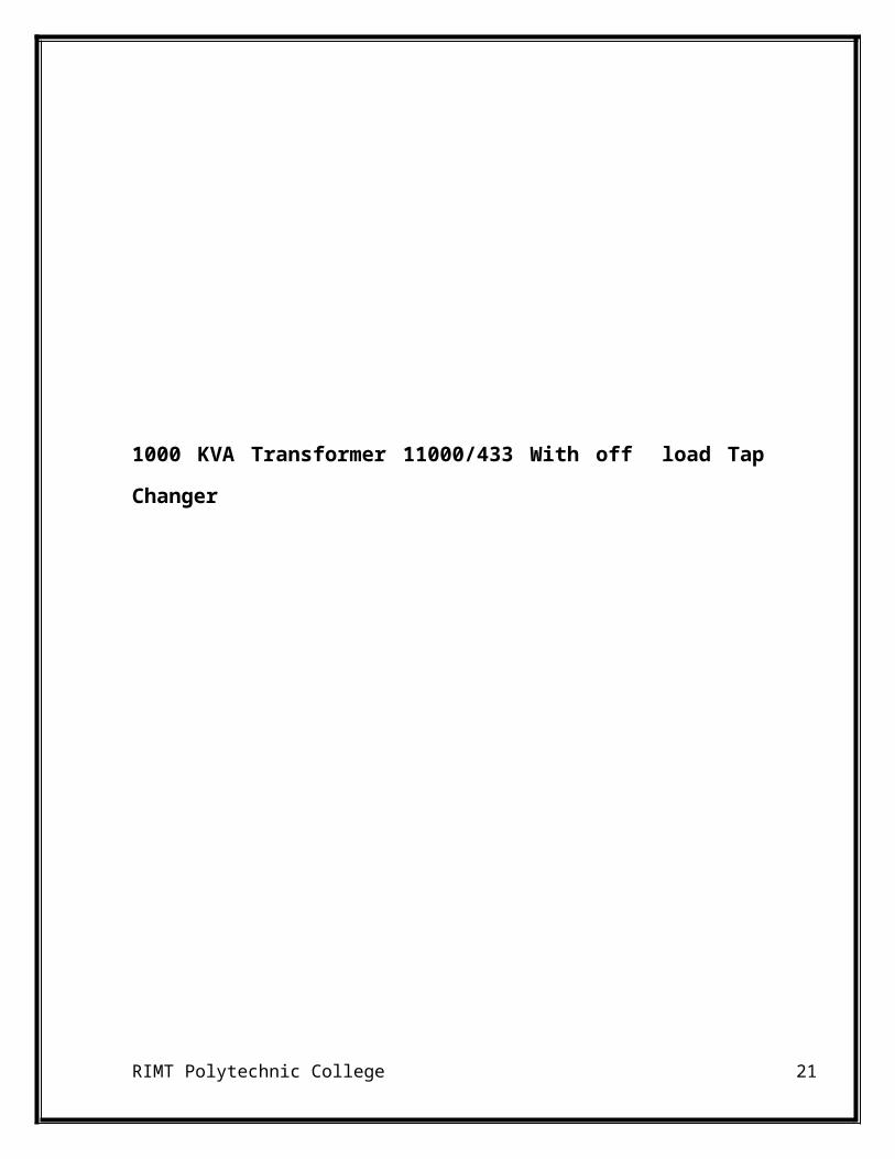
1000 KVA Transformer 11000/433 With off load Tap Changer
RIMT Polytechnic College 15
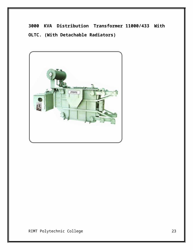
3000 KVA Distribution Transformer 11000/433 With OLTC. (With
Detachable Radiators)
RIMT Polytechnic College 16
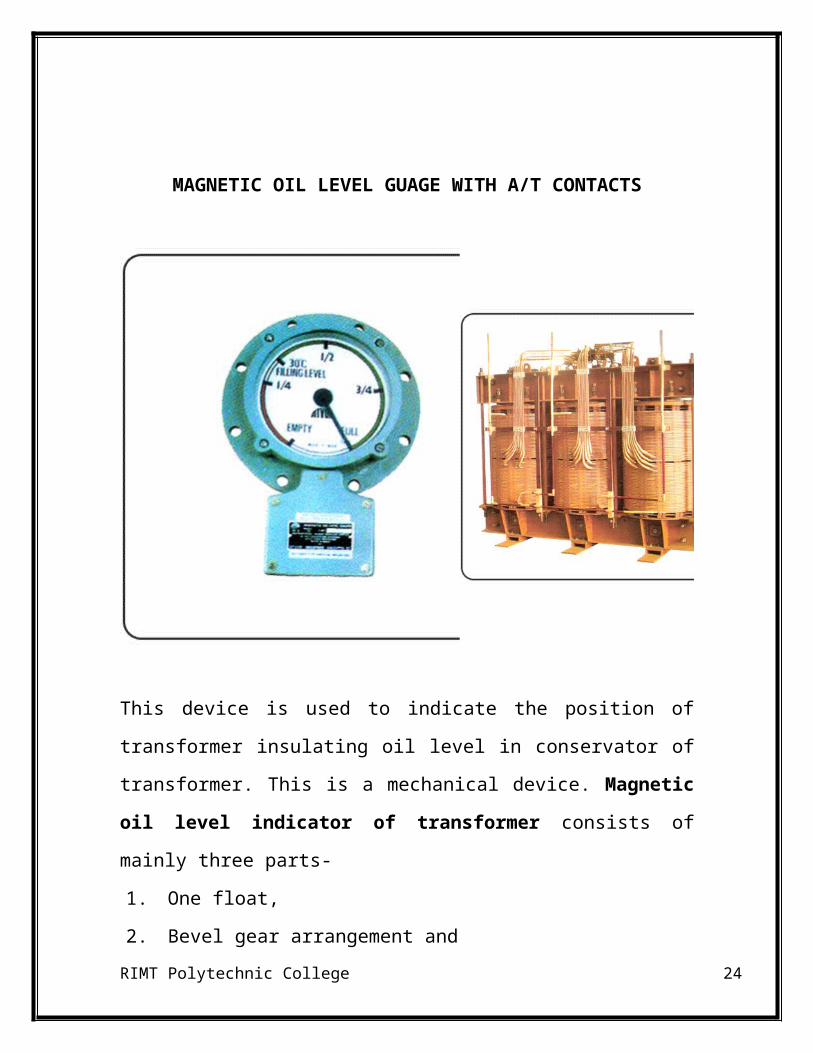
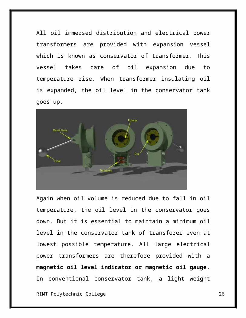
MAGNETIC OIL LEVEL GUAGE WITH A/T CONTACTS
This device is used to indicate the position of transformer insulating oil level
in conservator of transformer. This is a mechanical device. Magnetic oil
level indicator of transformer consists of mainly three parts-
1. One float,
2. Bevel gear arrangement and
3. An indicating dial.
RIMT Polytechnic College 17
Construction of Magnetic Oil Gauge or MOG
Let’s explain the construction of magnetic oil gauge or MOG from its dial
parts. The dial of this device has scale from empty to full. It has some
intermediate divisions such as 1/4, 1/1, 3/4. The prescribed oil level at either
30°C or 35°C ambient temperature may also be indicated on the dial. A
mercury switch and bevel gear is fixed with pointer. When pointer rotates,
the alignment of mercury switch also changes according to the angle of
rotation of the pointer. One ball type or drum type float is attached with a
sufficiently long float arm. One unit of bevel gear is fitted on the other side
of the float arm. Other unit of the bevel gear is magnetically coupled with
pointer and mercury switch arrangement. The bevel gear arrangement is
positioned inside the conservator tank of transformer and dial, pointer and
mercury switch are positioned outside the conservator tank.
Working Principle of Magnetic Oil Gauge or MOG
All oil immersed distribution and electrical power transformers are provided
with expansion vessel which is known as conservator of transformer. This
vessel takes care of oil expansion due to temperature rise. When transformer
insulating oil is expanded, the oil level in the conservator tank goes up.
RIMT Polytechnic College 18
Again when oil volume is reduced due to fall in oil temperature, the oil level
in the conservator goes down. But it is essential to maintain a minimum oil
level in the conservator tank of transforer even at lowest possible
temperature. All large electrical power transformers are therefore provided
with a magnetic oil level indicator or magnetic oil gauge. In conventional
conservator tank, a light weight hollow ball or drum floats on the
transformer insulating oil. The float arm is attached with bevel gear as we
already explained during the discussion on the construction of magnetic oil
gauge. Naturally the position of the float goes up and down depending upon
the oil level in the conservator and consequently the alignment of float arm
changes. Consequently, the bevel gear rotates. This movement of bevel gear
is transmitted to the pointer outside the conservator, as this pointer is
magnetically coupled with the bevel gear. The pointer of magnetic oil level
indicator is also incorporated with a mercury switch. So it is need not say,
when oil level in the conservator goes up and down, the pointer moves on
the MOG dial to indicate the actual level of transformer insulating oil in
conservator tank. As the alignment of mercury switch changes along with
the pointer, this switch closes and actuates an audible alarm when pointer
RIMT Polytechnic College 19

reaches near empty position on the dial of magnetic oil gauge. This event
alerts us for topping up oil in electrical power transformer.
Again when oil volume is reduced due to fall in oil temperature, the oil level
in the conservator goes down. But it is essential to maintain a minimum oil
level in the conservator tank of transforer even at lowest possible
temperature. All large electrical power transformers are therefore provided
with a magnetic oil level indicator or magnetic oil gauge. In conventional
conservator tank, a light weight hollow ball or drum floats on the
transformer insulating oil. The float arm is attached with bevel gear as we
already explained during the discussion on the construction of magnetic oil
gauge. Naturally the position of the float goes up and down depending upon
the oil level in the conservator and consequently the alignment of float arm
changes. Consequently, the bevel gear rotates. This movement of bevel gear
is transmitted to the pointer outside the conservator, as this pointer is
magnetically coupled with the bevel gear. The pointer of magnetic oil level
indicator is also incorporated with a mercury switch. So it is need not say,
when oil level in the conservator goes up and down, the pointer moves on
the MOG dial to indicate the actual level of transformer insulating oil in
conservator tank. As the alignment of mercury switch changes along with
the pointer, this switch closes and actuates an audible alarm when pointer
reaches near empty position on the dial of magnetic oil gauge. This event
alerts us for topping up oil in electrical power transformer.
In air cell conservator, the float arm is attached with air cell and alignment
of float arm changes with the changing size of air cell due to the expansion
and contraction of oil.
RIMT Polytechnic College 20
VOLTAGE STABILIZERS
A voltage Stabilizers is designed to automatically maintain a constant
voltage level. A voltage regulator may be a simple "feed-forward" design or
may include negative feedback control loops. It may use an
electromechanical mechanism, or electronic components. Depending on the
design, it may be used to regulate one or more ACor DC voltages.
Electronic voltage Stabilizers are found in devices such as computer power
supplieswhere they stabilize the DC voltages used by the processor and
other elements. In automobile alternators and central power station generator
plants, voltage regulators control the output of the plant. In an electric power
distribution system, voltage regulators may be installed at a substation or
along distribution lines so that all customers receive steady voltage
independent of how much power is drawn from the line.
DC Voltage Stabilizers
Many simple DC power supplies regulate the voltage using either series or
shunt regulators, but most apply a voltage reference using a shunt
regulator such as aZener diode, avalanche breakdown diode, or voltage
regulator tube. Each of these devices begins conducting at a specified
voltage and will conduct as much current as required to hold its terminal
RIMT Polytechnic College 21
voltage to that specified voltage by diverting excess current from a non-ideal
power source to ground, often through a relatively low-value resistor to
dissipate the excess energy. The power supply is designed to only supply a
maximum amount of current that is within the safe operating capability of
the shunt regulating device.
If the stabilizer must provide more power, the shunt regulator output is only
used to provide the standard voltage reference for the electronic device,
known as the voltage stabilizer. The voltage stabilizer is the electronic
device, able to deliver much larger currents on demand.
Measures of regulators quality
The output voltage can only be held roughly constant. The regulation is
specified by two measurements:
Load regulation is the change in output voltage for a given change in
load current (for example, "typically 15 mV, maximum 100 mV for
load currents between 5 mA and 1.4 A, at some specified temperature
and input voltage").
Line regulation or input regulation is the degree to which output
voltage changes with input (supply) voltage changes - as a ratio of
output to input change (for example, "typically 13 mV/V"), or the
output voltage change over the entire specified input voltage range
(for example, "plus or minus 2% for input voltages between 90 V and
260 V, 50-60 Hz").
Other important parameters are:
RIMT Polytechnic College 22
Temperature coefficient of the output voltage is the change with
temperature (perhaps averaged over a given temperature range).
Initial accuracy of a voltage regulator (or simply "the voltage
accuracy") reflects the error in output voltage for a fixed regulator
without taking into account temperature or aging effects on output
accuracy.
Dropout voltage is the minimum difference between input voltage
and output voltage for which the regulator can still supply the
specified current. A low drop-out (LDO) regulator is designed to work
well even with an input supply of only aVolt or so above the output
voltage. The input-output differential at which the voltage regulator
will no longer maintain regulation is the dropout voltage. Further
reduction in input voltage will result in reduced output voltage. This
value is dependent on load current and junction temperature.
Absolute maximum ratings are defined for regulator components,
specifying the continuous and peak output currents that may be used
(sometimes internally limited), the maximum input voltage, maximum
power dissipation at a given temperature, etc.
Output noise (thermal white noise) and output dynamic
impedance may be specified as graphs versus frequency, while
output ripple noise (mains "hum" or switch-mode "hash" noise) may
be given as peak-to-peak or RMS voltages, or in terms of their
spectra.
Quiescent current in a regulator circuit is the current drawn
internally, not available to the load, normally measured as the input
current while no load is connected and hence a source of inefficiency
RIMT Polytechnic College 23
(some linear regulators are, surprisingly, more efficient at very low
current loads than switch-mode designs because of this).
Transient response is the reaction of a regulator when a (sudden)
change of the load current (called the load transient) or input voltage
(called the line transient) occurs. Some regulators will tend to
oscillate or have a slow response time which in some cases might lead
to undesired results. This value is different from the regulation
parameters, as that is the stable situation definition. The transient
response shows the behaviour of the regulator on a change. This data
is usually provided in the technical documentation of a regulator and
is also dependent on output capacitance.
Mirror-image insertion protection means that a regulator is
designed for use when a voltage, usually not higher than the
maximum input voltage of the regulator, is applied to its output pin
while its input terminal is at a low voltage, volt-free or grounded.
Some regulators can continuously withstand this situation. Others
might only manage it for a limited time such as 60 seconds (usually
specified in the data sheet). For instance, this situation can occur when
a three terminal regulator is incorrectly mounted on a PCB, with the
output terminal connected to the unregulated DC input and the input
connected to the load. Mirror-image insertion protection is also
important when a regulator circuit is used in battery charging circuits,
when external power fails or is not turned on and the output terminal
remains at battery voltage.
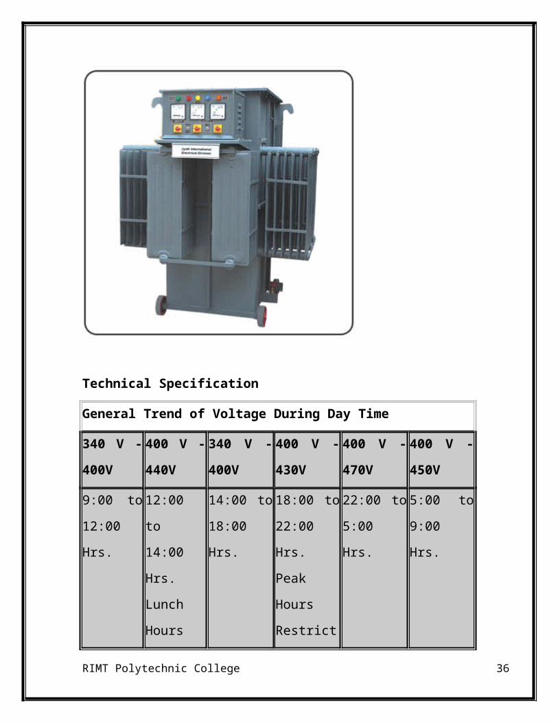
SERVO VOLTAGE STABILIZERS From 20 KVA to 5000 KVA
RIMT Polytechnic College 24
Technical Specification
General Trend of Voltage During Day Time
340 V -
400V
400 V -
440V
340 V -
400V
400 V -
430V
400 V -
470V
400 V -
450V
9:00 to
12:00 Hrs.
12:00 to
14:00 Hrs.
Lunch
Hours
14:00 to
18:00 Hrs.
18:00 to
22:00 Hrs.
Peak Hours
Restriction
22:00 to
5:00 Hrs.
5:00 to 9:00
Hrs.
We have supplied more than 2000 Automotive Voltage Controller,
Rectifiers & Transformers above 100 KVA capacity to different type of
RIMT Polytechnic College 25
industries/required corporate houses throughout India as well as few
outside India. As per customers feedback they are working to their full
satisfaction and hence getting repeat orders from them. The equipment is
the need of every power consumer.
Industrial Robot
Automatic Voltage Controller is an industrial robot which first monitors
items rectifiers the voltage variation round the clock & whenever there is
any voltage fluctuation, it rectifiers to the desired level in few seconds.
The Basic purpose of AVC is to maintain the desired voltage and to reduce
the breakdown of electrical equipments due to low/high voltage. Power
saving Reduction in MDI and improvement of P.F. will be added
advantages at high voltage.
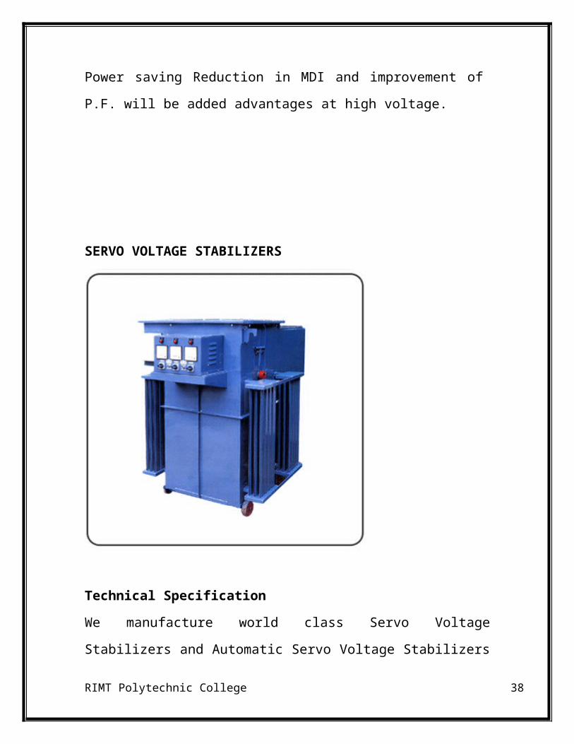
SERVO VOLTAGE STABILIZERS
RIMT Polytechnic College 26
Technical Specification
We manufacture world class Servo Voltage Stabilizers and Automatic Servo
Voltage Stabilizers in Air/Oil Cooled Constructions for both LT & HT Lines
from 10 KVA to 5000 KVA. The Equipment has been designed according to
the International Standards.
CONTROL PANELRIMT Polytechnic College 27
A control panel is a flat, often vertical, area where control or monitoring
instruments are displayed. They are found in factories to monitor and control
machines or production lines and in places such as nuclear power
plants, ships, aircraft andmainframe computers. Older control panels are
most often equipped with push buttons and analog instruments, whereas
today in many cases touchscreens are used for monitoring and control
purposes.
CABLES
Cables are used for the interconnection. Two types of cables are used. Power
cable and control cable.
1. Power cables (which is used to connect the motor to panel component and
panel to main supply
2. Control cables (which is used to connect the control circuits)
BUS BAR
BUS BAR
RIMT Polytechnic College 28
Incoming supply is connected to bus bar and distributed from bus bar. It is
normally made by Aluminum.
MCB (Miniature Circuit Breakers
MCB is a protecting device. It is used before the feeder. This should be
selected according to the capacity of the feeder
MCCB (Mould Case Circuit Breaker)
RIMT Polytechnic College 29
In most of the cases the MCCB used as an incomer for higher capacity
feeders for better protection
ELCB (Earth Leakage Circuit Breaker)
The ELCB is also known as RCCB. The device used for the protection
against the earth leakage current and residual current. It should be fixed
before the incomer
INCOMER
The basic supply will connected to this incomer. It also called as
RIMT Polytechnic College 30
SFU(Switch Fuse Unit). It contains one handle with fuse unit. Once it is
turned ON the supply will pass to the next stage through fuse if any major
fault occurs in side panel board, it will trip and it isolate supply.
SELECTOR SWITCH
Selector is switch is used for ON/OFF purpose and for selecting the mode of
operation like auto/manual.
Starters are used for starting the motors safely. Mainly two types of starters
are there. DOL starters and Start to delta. Dol starter is enough for the
motors with power less than 10 hp.
RIMT Polytechnic College 31
OVER LOAD RELAY
Over load relay is for the protection of motor from the over load. It senses
the load current and trips if it exceeds the limit. Current limit has to be set
manually. It should be 80% of the full load current.
RIMT Polytechnic College 32
TIMER
Operation of timer is similar to relay. But a delay is there for actuation. We
can set the time delay manually according to our requirement. It is very
much essential for start to delta conversion.
RIMT Polytechnic College 33
CONTACTOR
Contactor is an essential component in the control panel. It actuates when
the signal from the controller (PLC, Relay logic) comes. It is similar to
relay. It is costlier than relay. It is used for a higher load.
RIMT Polytechnic College 34
RIMT Polytechnic College 35
CONTROL PANEL
Technical Specification
We are manufacturer of control panels for light & heavy industrial
Purpose. The circuit is designed by our engineer to fulfill the customer’s
need. We give our best service during installation and in future, we provide
the detailed control panel diagram.
We offer electric panels that are used to supply power electrical motors and
equipment’s.
The range of electrical control panels we offer include :
Motor Control Centres
RIMT Polytechnic College 36
Distribution Boards
Automatic PF. Correction Panels
Power Control Centres
Panels for PLC Machinery
AC/DC dry Panels
RIMT Polytechnic College 37
REFERENCES
http://jyotitransformers.com/
http://jyotitransformers.com/products.html
https://en.wikipedia.org/.../Distribution_transfo..
RIMT Polytechnic College 38