justin cheung - portfolio
DESCRIPTION
A collection of work from the John H. Daniels Faculty of Architecture, Landscape, and Urban Design Masters programTRANSCRIPT

_Submerged: Modular Ecologies for Shark Mangement
_Diavik Diamond Mine Rehabilitation
_Farm to Fill
_All the Above
_Don River Park Project
_Fractured Landscapes_Infrastructure Lifecycles
_Mixed Media
Contents

Submerged: Modular Ecologies for Shark ManagementLAN3017Y - ThesisWinter 2011
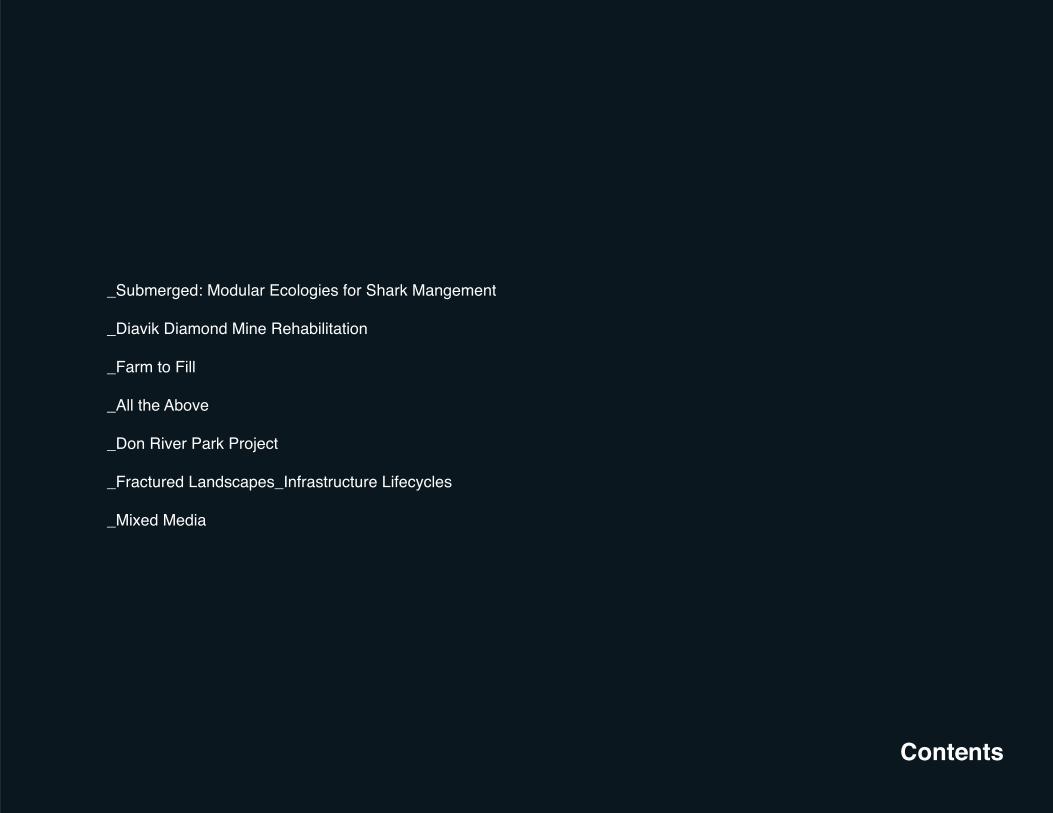
As the fi eld of Landscape Architecture continues to evolve and create dynamic terrestrial landscapes, this thesis sought to examine the aquatic landscape as a potential new frontier for Landscape Architecture. The current practice for artifi cial reef construction is to use decommissioned materials such as planes, ships, or automobiles, and sink them to the bottom of the ocean. However, the long term effects of these practices have yet to be determined. As these sites are used as recreational diving sites, it often creates a one dimensional experience for the divers. By creating a full designed artifi cial reef, it would create a variety of experiences, as well as numerous different types of habitats to promote fi sh and coral growth.
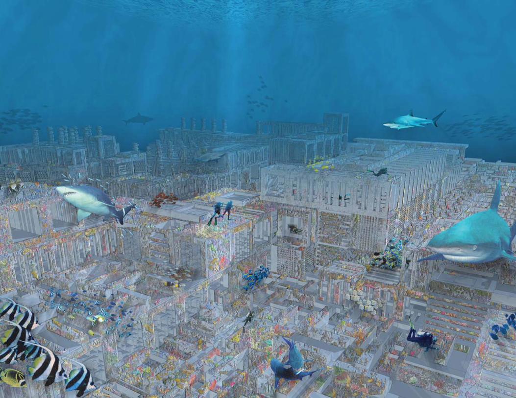
For many years, within the Sydney area there has been a myth that Bull Sharks had began to expand into local rivers and lakes. However, this myth has become all to real, with numerous sightings and attacks found within Sydney Harbour, and its connecting estuaries. Since 2002, shark attacks in canals and rivers are on the rise, with sightings becoming an increasing trend within the Australian media. Typical sightings happen a few miles inland, usually in brackish water.
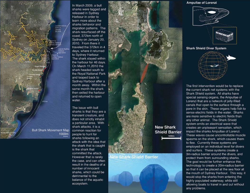
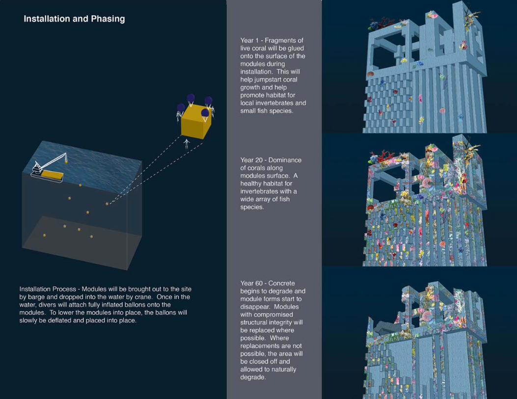
The goal of this thesis was to create a designed artifi cial reef, that would build a food source for the Bull Shark away from the harbour, and to create a diving site that created a variety of experiences that cannot be found at any other diving locations. The designed reef will be made up of 3m by 3m-modular cubes that are made from pH neutral concrete. These modular cubes will increase the surface area for coral growth, and will be designed to enhance the human experience for reef diving. Concrete was chosen as the material of choice due to its ability to not change the chemical makeup of the water as it degrades, its 60-year lifespan, and its ability to take on a variety of forms. Though the concepts of scale, open and closed spaces, the form of this new artifi cial reef will create various conditions of light exposure and water fl ow, that would create habitats to accommodate a wide array of aquatic species. Rather than sinking decommissioned objects, these modular systems will allow for a fully designed reef system that can be used to create new experiences for scuba divers. There are four modular types that will be formed, coral block modules, habitat modules, tunnel modules and low-level modules. The coral block modules will be used to maximize the surface area to promote coral growth and invertebrate habitats. The habitat modules create a variety of spaces to allow for both habitat and hiding spaces for invertebrates and medium to larger fi sh species. The tunnel modules will create spaces to allow divers to travel through the reef, creating an experience that cannot be found in other artifi cial reefs. The low-level modules are designed to increase surface area for coral growth.


The above reef design is only a small portion of the entire reef system, and is an example of how the modules can be placed together. This designed area is delineated in the site plan as the area in yellow. This section of reef covers 5886 square meter of ocean fl oor, and fi ve different levels, reaching a maximum height of 15m. There are a total of 1036 modules that are used.
The four module types are divided within the reef design, representing how the modules will be used and where they would be placed within the reef. The low level modules will be placed on top of open spaces in the reef to increase surface area for coral growth and invertebrate habitats. The Tunnel Modules will allow for movement within the reef, creating pathways that travel both horizontally and vertically, providing a new experience for divers. The Habitat modules are palced along all levels of the reef to provide habitats for a variety of fi sh species. The Coral Block modules are more solid in form, and will be used more as a support module for the reef. These modules will be placed along the base of the reef and will make up the largest portion of the reef.


Diavik Diamond Mine Rehabilitation LAN3016Y - Design Studio OptionFall 2010
When the public considers Canada’s natural resources, the immediate answers are usually fi sheries, wheat, or lumber. It was the goal of this project to highlight one of Canada’s unknown resources, as well as to develop a strategy to reclaiming these sites upon decommission.
The Diavik Diamond Mine has become one of the largest producers of diamonds in the world, producing over 8 million carats of diamonds, and grossing over $100 million in sales. The mines are found on a 20 square km island, within Lac de Gras, in the Northwest Territories, Canada. The fully functioning diamond mine includes an airstrip, power plant, sewage plant, processing plant, and permenant accomodations.
Surrounding the site, the region features a vast arctic landscape, that has a number of local wildlife species, including the caribou, grizzly bear, and arctic wolves. As a way to highlight both the dynamic mine landscape, as well as the wildlife around it, the fi rst stage was to create a 130m tall tower. The tower supports a viewing ball, which is suspended into the mine itself. From the top of the tower, it allows people to see the surrounding landscape, the migration patterns that occur in the region. By allowing people to enter the mine, it highlights the dramatic forms that are created through the mining process.
With the mining processes expected to be completed in 2020, the next stage would be to rehabilitate the site, and create a wolverine preserve, while reusing the existing landscapes and infrastructure. The goal would be to use the open mine pits as an area to raise wolverines in an area protected from predators and the natural elements. Additionally, the exisitng viewing ball would allow researchers to examine previously unseen wolverine behaviors, to aid in bringing these creatures out of its threatened status. By condensing the necessary infrastructure into a single area, the island would be converted into a sanctuary, to allow wolverines to grow and thrive before being released into the wild. Furthermore, unnecessary infrastructure, such as roads, would be deconstructed, and used as shelters and placed throughout the island.
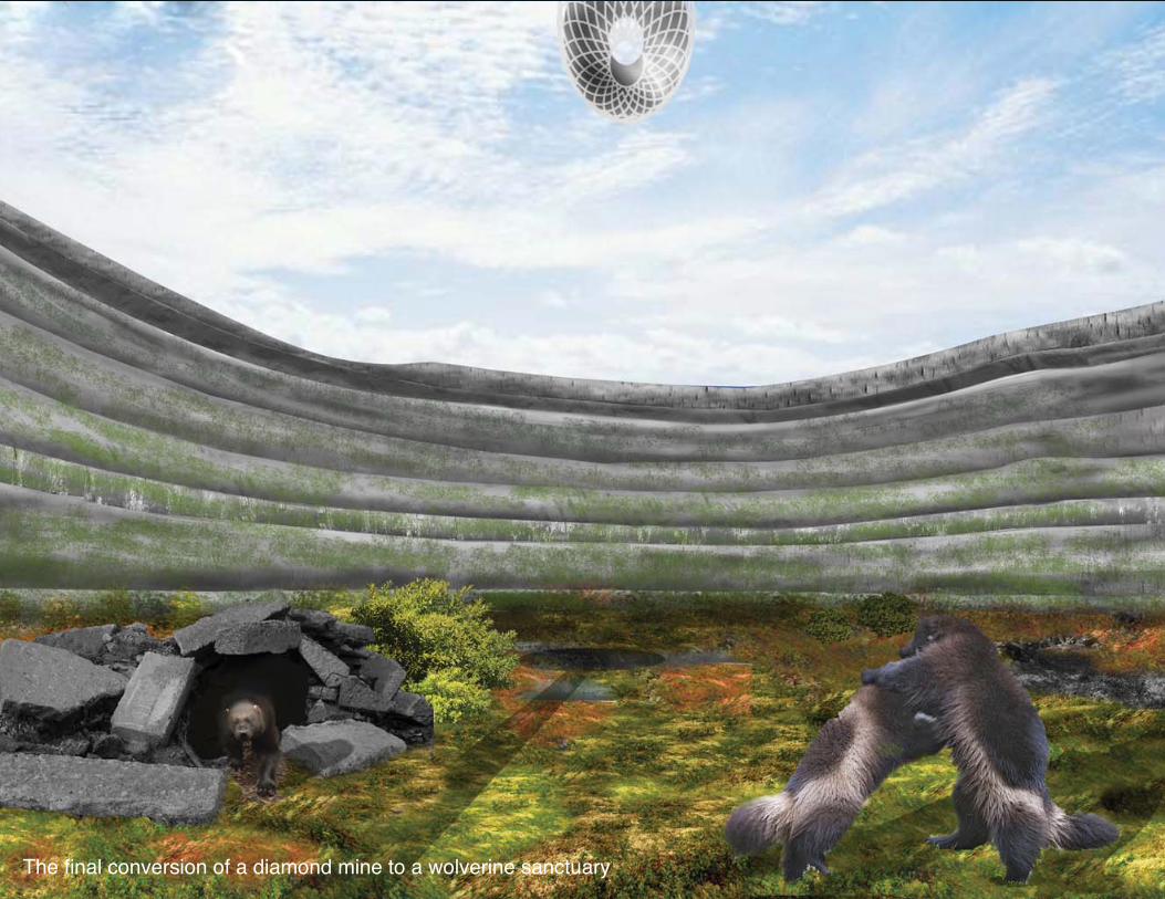
The fi nal conversion of a diamond mine to a wolverine sanctuary
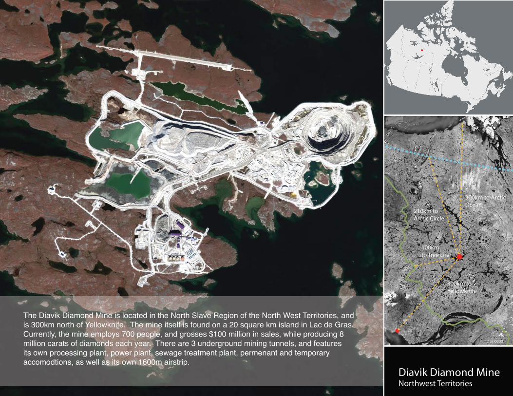
Diavik Diamond MineNorthwest Territories
1:1500000
The Diavik Diamond Mine is located in the North Slave Region of the North West Territories, and is 300km north of Yellowknife. The mine itself is found on a 20 square km island in Lac de Gras. Currently, the mine employs 700 people, and grosses $100 million in sales, while producing 8 million carats of diamonds each year. There are 3 underground mining tunnels, and features its own processing plant, power plant, sewage treatment plant, permenant and temporary accomodtions, as well as its own 1600m airstrip.
Male Female
Grizzly Bear Grey Wolf
Wolverine Range (Threatened) Peregrine Falcon Range (Threatened)
Post Calving Migration
Calving Grounds
Fall Migration
Spring Migration
Caribou
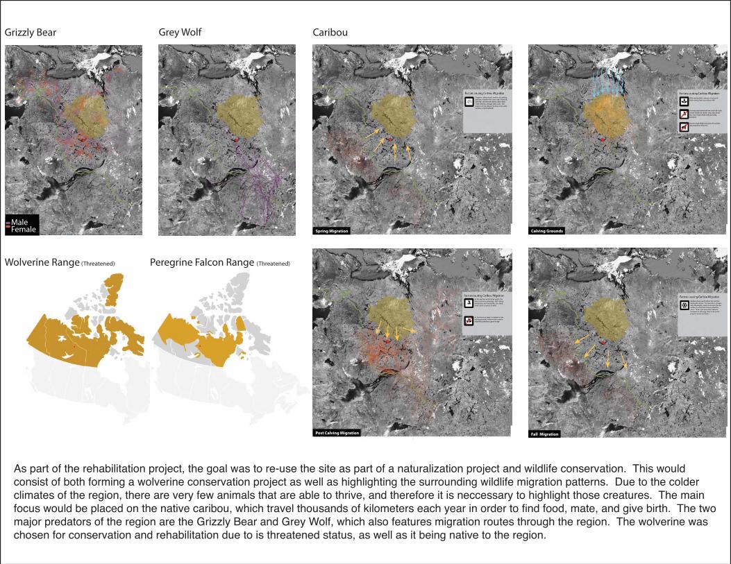
As part of the rehabilitation project, the goal was to re-use the site as part of a naturalization project and wildlife conservation. This would consist of both forming a wolverine conservation project as well as highlighting the surrounding wildlife migration patterns. Due to the colder climates of the region, there are very few animals that are able to thrive, and therefore it is neccessary to highlight those creatures. The main focus would be placed on the native caribou, which travel thousands of kilometers each year in order to fi nd food, mate, and give birth. The two major predators of the region are the Grizzly Bear and Grey Wolf, which also features migration routes through the region. The wolverine was chosen for conservation and rehabilitation due to is threatened status, as well as it being native to the region.

The fi rst stage in the rehabilitation project would be to remove the uneccessary site features that were used for the mining process, and creating a central facility for researchers, which would be located at the mines. The airstrip would remain for transport, but many of the roads and materials would be reused where possible for creating habitats and shelters throughout the island. There are seven vegetation types that will be planted throughout the site. The Sedge Tussock will be planted along the coast of the island. The Dwarf Birch, Northern Labrador Tea, Blueberry, Mountain Cranberry, Bearberry, Sphagum Moss will be planted throughout the site to create variations of height, density and colours.

320m
130m
90m
190m
Mine A514 Section
1:2000
Sedge Tussock
Dwarf Birch
Northern Labrador
Tea
Blueberry
Mountain Cranberry
Bearberry
Sphagum MossGroundcover peat
Legend
Mine Vegetation Plan
1:3000
Along the mine, and 130m tall tower will be placed as a research station. At 130m, researchers would be able to see 42km to the horizon which would allow for the observation of the surrounding migration routes. The tower supports an observation ball which extends 320m into the centre of mine and 90m into the mine itself. This ball will be supported by suspension cables, and allow the researchers to obvserve the mine below, which will be used as a wolverine pen. This would allow the wolverines to grow and thrive, and raise their young in safety from local predators. The mine will also be planted, with several hides made from reused concrete and logs to create a suitable habitat.
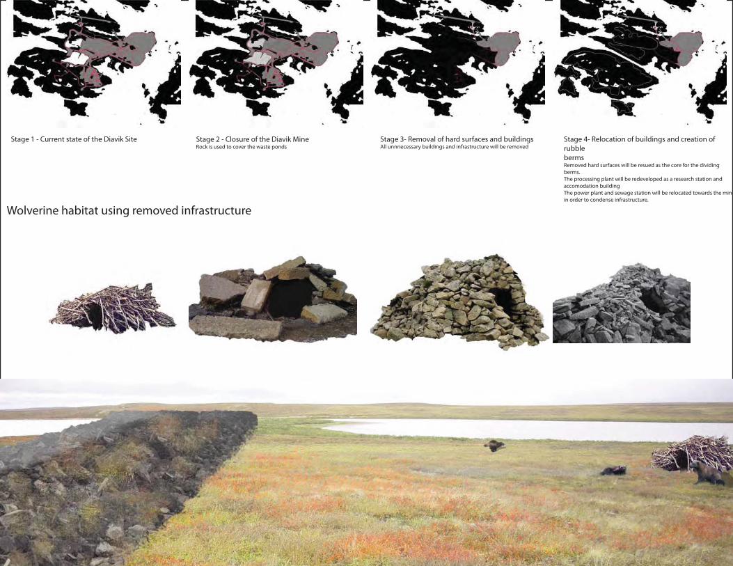
Stage 1 - Current state of the Diavik Site Stage 2 - Closure of the Diavik MineRock is used to cover the waste ponds
Stage 3- Removal of hard surfaces and buildingsAll unnnecessary buildings and infrastructure will be removed
Stage 4- Relocation of buildings and creation of
rubble
bermsRemoved hard surfaces will be resued as the core for the dividing
berms.
The processing plant will be redeveloped as a research station and
accomodation building
The power plant and sewage station will be relocated towards the mine
in order to condense infrastructure.
Wolverine habitat using removed infrastructure

Farm To FillLAN2014Y - Design Studio 4 Winter 2010
As the City of New Orleans seeks to reclaim the MRGO, the closure structure looks to restore the freshwater marshes, and many of the reports have neglected to consider what effects the closure would have on the salt marshes to the south. Although salt marshes are seen as positive infl uences towards a healthy ecology in other locations, many of the studies done for this structure fail to discuss the topic.
The barrier structure will alter the current conditions of the New Orleans area, creating a distinctive seperation of salinity and marsh types around the MRGO. This project looks to reclaim the salt marshes, and create a condition that will have both an ecological and economic benifi t to the New Orleans landscape.
The strategy involves restoring the salt marshes in several phases. The fi rst of which is to use the black mangrove as a tool to stabalize the shoreline, and limit the amount of erosion that is currently occuring. Once stable, the strategy seeks to maintain the economical character of the MRGO with the installation of crab ponds and oyster lines for both commercial and recreational aquaculture. Along with providing an economical boost to the surrounding communities, and adhearing to the aquafarming culture of New Orleans, the aquaculture systems would be placed along pinch points within the MRGO. As a method to slow down the water’s fl ow, the goal is to allow for sediment deposition within the area to the north of ther farming systems. Once the area has been reclaimed and transformed back into a salt marsh condition, the next stage will move to the next chosen pinch point to the south and continue the process of land building through aquaculture. As a result this strategy looks to rebuild the salt marshes while providing a simulatneous economic benifi t.

Farm to FillSalinity
New Orleans
Site
Brackish
Fresh Intermediate
OutSaline
Water
1”=65000’ Marsh Types
New Orleans
Site
swamp
scrub-shrub_wetland
salt_marsh
intermediate_marsh
brackish_marsh
fresh_marsh
1”=65000’ Coastal Erosion
Original Width
Eroded Coastal Area
10500’
New Orleans
Site
MRGO Closure Barrier
The three major issues to the area that affected the project was the salinity of the water, the types of marshes in the area, and the coastal erosion of the Mississippi River Gulf Outlet. These issues had a direct relationship with the type of aquaculture that could be use for this project. As coastal erosion has caused a major expansion in the width of the waterway, the project looked to use local vegatation to help reduce coastal erosion
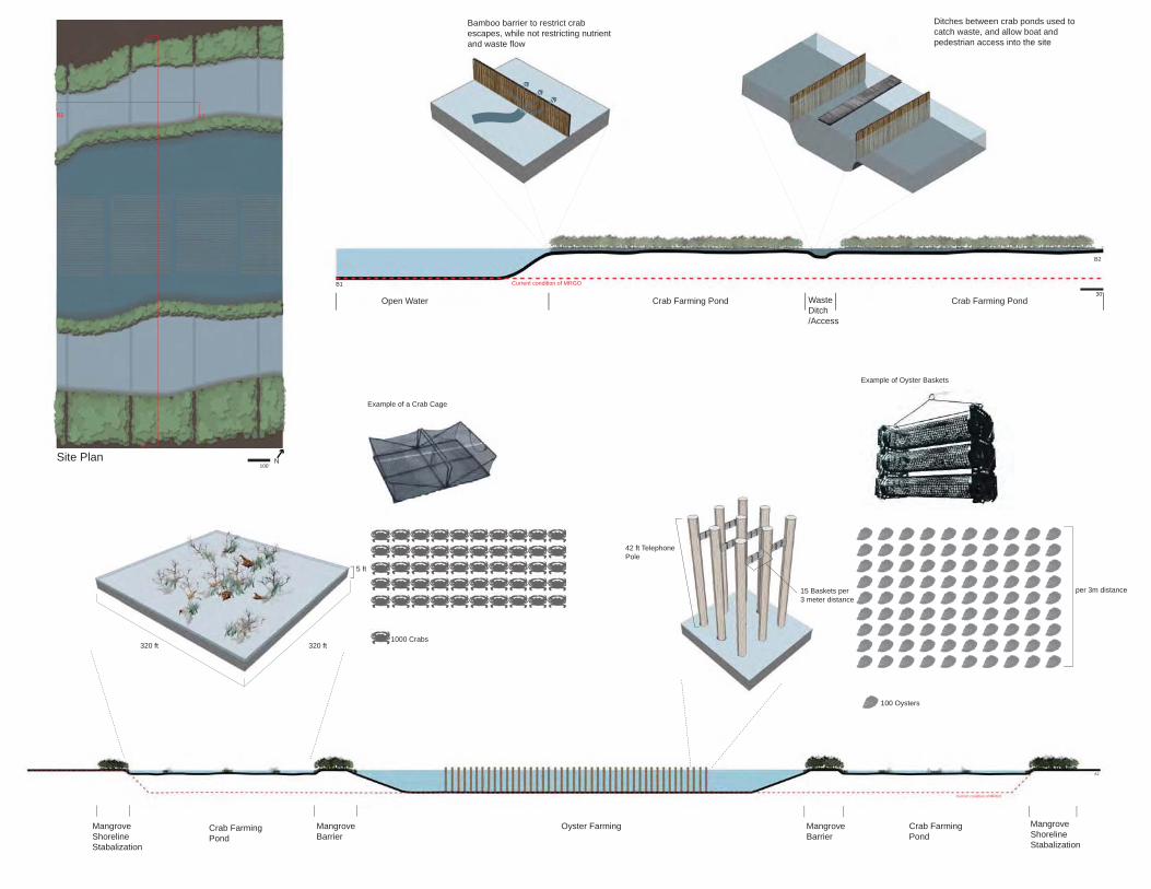
MangroveShorelineStabalization
30’
A1
Crab Farming Pond
MangroveBarrier
Oyster Farming Mangrove Barrier
Crab Farming Pond
MangroveShorelineStabalization
Current condition of MRGO
A2
320 ft
5 ft
320 ft1000 Crabs
42 ft Telephone Pole
15 Baskets per 3 meter distance
100 Oysters
per 3m distance
Example of a Crab Cage
Example of Oyster Baskets
Bamboo barrier to restrict crab escapes, while not restricting nutrient and waste flow
30’Waste Ditch/Access
Crab Farming PondCrab Farming PondOpen Water
B2
Current condition of MRGO
Ditches between crab ponds used to catch waste, and allow boat and pedestrian access into the site
B1
100’Site Plan
A1
B2B1
A2
N
1500’
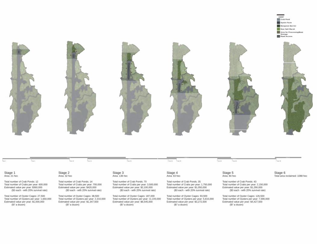
Stage 1Stage 2
Stage 3
Year 1 Year 5 Year 10 Year 15 Year 20
Stage 2
Area: 32 hec
Total number of Crab Ponds: 14Total number of Crabs per year: 700,000Estimated value per year: $420,000 ( $3 each - with 20% survival rate)
Total number of Oyster Cages: 38,5000Total number of Oysters per year: 2,310,000 Estimated value per year: $1,347,500 ($7 a dozen)
Stage 3Area: 136 hec
Total number of Crab Ponds: 70Total number of Crabs per year: 3,500,000Estimated value per year: $2,100,000 ( $3 each - with 20% survival rate)
Total number of Oyster Cages: 187,000Total number of Oysters per year: 11,220,000 Estimated value per year: $6,545,000 ($7 a dozen)
Stage 1Area: 21 hec
Total number of Crab Ponds: 12Total number of Crabs per year: 600,000 (50,000 crabs per hectare)Estimated value per year: $360,000 ( $3 each - with 20% survival rate)
Total number of Oyster Cages: 27,500 (5500 baskets per hectareTotal number of Oysters per year: 1,650,000 (6 oysters per basket)Estimated value per year: $1,000,000 ($7 a dozen)
Mangrove Barrier
Crab Pond
Oyster Farm
Road Access
New Salt Marsh
Area for Processing/Boat Storage
Stage 4Stage 5
Stage 6
Year 35 Year 40 Year 50 Year 55 Year 65
Stage 6Total area reclaimed as salt marsh: 1088 hectares
Stage 4
Area: 63 hec
Total number of Crab Ponds: 35Total number of Crabs per year: 1,750,000Estimated value per year: $1,050,000 ( $3 each - with 20% survival rate)
Total number of Oyster Cages: 93,500Total number of Oysters per year: 5,610,000 Estimated value per year: $3,272,500 ($7 a dozen)
4 Stage 5
Area: 84 hec
Total number of Crab Ponds: 43Total number of Crabs per year: 2,150,000Estimated value per year: $1,290,000 ( $3 each - with 20% survival rate)
Total number of Oyster Cages: 126,500Total number of Oysters per year: 7,590,000 Estimated value per year: $4,427,500 ($7 a dozen)
1500’
Mangrove Barrier
Crab Pond
Oyster Farm
Road Access
New Salt Marsh
Area for Processing/Boat Storage
1500’
Mangrove Barrier
Crab Pond
Oyster Farm
Road Access
New Salt Marsh
Area for Processing/Boat Storage
Stage 1Area: 21 hec
Total number of Crab Ponds: 12Total number of Crabs per year: 600,000Estimated value per year: $360,000 ($3 each - with 20% survival rate)
Total number of Oyster Cages: 27,500Total number of Oysters per year: 1,650,000Estimated value per year: $1,000,000 ($7 a dozen)
Stage 2Area: 32 hec
Total number of Crab Ponds: 14Total number of Crabs per year: 700,000Estimated value per year: $420,000 ($3 each - with 20% survival rate)
Total number of Oyster Cages: 38,500Total number of Oysters per year: 2,310,000Estimated value per year: $1,347,500 ($7 a dozen)
Stage 3Area: 136 hec
Total number of Crab Ponds: 70Total number of Crabs per year: 3,500,000Estimated value per year: $2,100,000 ($3 each - with 20% survival rate)
Total number of Oyster Cages: 187,000Total number of Oysters per year: 11,220,000Estimated value per year: $6,545,000 ($7 a dozen)
Stage 4Area: 63 hec
Total number of Crab Ponds: 35Total number of Crabs per year: 1,750,000Estimated value per year: $1,050,000 ($3 each - with 20% survival rate)
Total number of Oyster Cages: 93,500Total number of Oysters per year: 5,610,000Estimated value per year: $3,272,500 ($7 a dozen)
Stage 5Area: 84 hec
Total number of Crab Ponds: 43Total number of Crabs per year: 2,150,000Estimated value per year: $1,290,000 ($3 each - with 20% survival rate)
Total number of Oyster Cages: 126,500Total number of Oysters per year: 7,590,000Estimated value per year: $4,427,500 ($7 a dozen)
Stage 6Total area reclaimed: 1088 hec
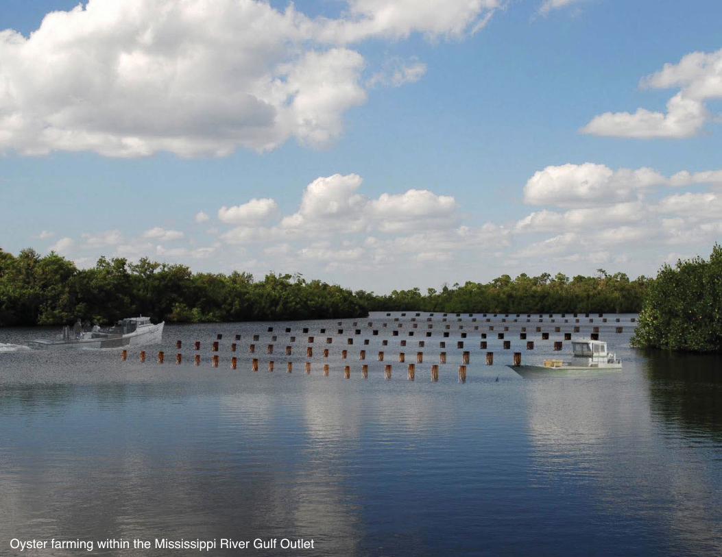
Oyster farming within the Mississippi River Gulf Outlet

Crab farming within the Mississippi River Gulf Outlet

All The AboveLAN2013Y - Design Studio 3Fall 2009
The Western Waterfront is an area spanning 4km in length, bounded by the Humber River to the west, Marilyn Ball Park to the east, Lake Ontario to the south, and the Lakeshore Blvd./Gardiner Expressway to the north. The primary purpose of this project was to develop a phased strategy that forms a structure towards the revitalization of a waterfront park system, which no longer meets the needs of its users.
This design concept looks to adhere to the current users of the park by creating various corridors based on the speed in which they travel through the park. The goal is to provide a different experience for three user groups, walking pedestrians, cyclists and roller bladers, and automobiles.
The automobile pathway will feature large native tree species in order to focus the drivers view forwards and acts as a traffi c calming measure.
Seeing that a majority of cyclists/roller bladers pass through the site without stopping, the goal was not to remove that activity, but to enhance it. The concept creates a high-speed pathway with entrances and exits only located at the east and west ends of the site. The pathway would also be lined with vegetation that grows to a maximum height of 2m. This would create a vegetative wall to limit access within the park, as well as used as a method to dedicate views.
The low speed pedestrian network is a large winding pathway that forms green space pockets, allowing for a variety of programming. These programs range from vegetative hideaways to sports fi elds. An elevated pathway will be formed at both ends of the site, above the Gardiner Expressway to provide added access to the site.
The high speed and low speed pathways will form a weave, allowing for both users to have direct access to the waterfront. Furthermore, within certain intersection points along the waterfront, sites will be dedicated as public beaches.

Vehicular Access
Point
Gardiner Expressway Exposed Areas Unviewable Areas Semi-Viewable Areas
High speed Pathway Low Speed Pathway Negative Zone
Exposed AreasLakeshore Blvd Unviewable Areas
Pedestrian Access
Point
Physical Barrier
ALLTHE
ABOVE
Access Points
Gardiner Expressway Exposure/Views Lakeshore Blvd Exposure/Views
Pedestrian Pathways

gies
Low Speed Pedestrian Pathway
Low Speed Vegetation Pathway
Pedestrian Activity Pockets
High Speed Pedestrian Pathway
High Speed Vegetation Pathway
Vegetation Buffer
Vehicular Pathway
The low speed pedestrian network will establish a pedestrian only network for casual usage. The meandering nature of the pathway will act as a means to decrease speeds within the pathways. Additionally, the meandering will create separate pockets of spaces that will be utilized for public usage, ranging from casual green spaces, hidden gardens, to active green spaces for sports. The vegetation pathway will be formed along side the path itself in order to act as a buffer, or to direct views for the user. These vegetation species will consist mainly of low to the ground vegetation.
The high speed network will be designed as a non-stop pathway for cyclists and joggers. This will allow these users to travel through the site without causing danger to the low speed users. The pathway meanders slightly to enhance views for the user and provide a greater experience of the site then what was previously available. The vegetation along site the pathway will be medium height. In doing so, along various sections of the pathway, it will create a vegetation tunnel, where in others it will be used to direct views for the high speed users.
The vegetation buffers will be used within the interspacial green space along the vehicular networks. These buffers will aid in decreasing the exposure of the vehicular pathways onto the site, in terms of both noise and automobile pollution. Also, by using tall tree species, it will create an enclosed senstation along the roadways, and provide a more natural experience for those travelling at very high speeds.
Site Plan
Phasing
0m 50m
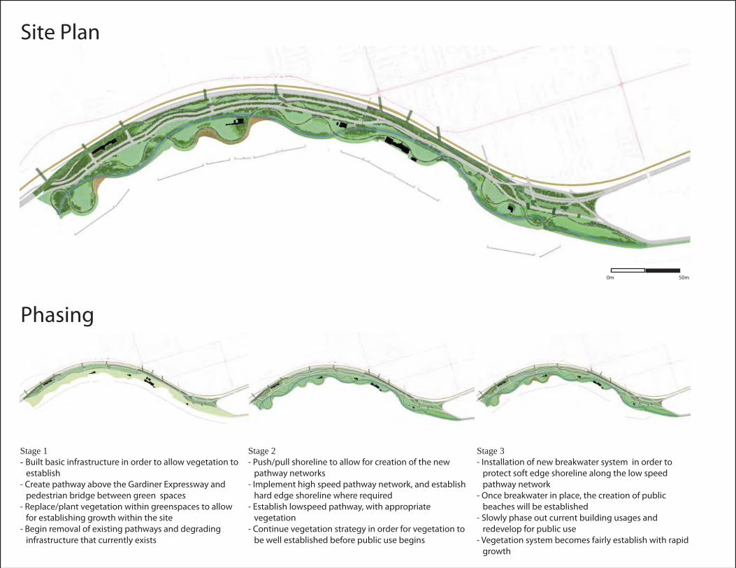
Stage 1- Built basic infrastructure in order to allow vegetation to
establish
- Create pathway above the Gardiner Expressway and
pedestrian bridge between green spaces
- Replace/plant vegetation within greenspaces to allow
for establishing growth within the site
- Begin removal of existing pathways and degrading
infrastructure that currently exists
Stage 2- Push/pull shoreline to allow for creation of the new
pathway networks
- Implement high speed pathway network, and establish
hard edge shoreline where required
- Establish lowspeed pathway, with appropriate
vegetation
- Continue vegetation strategy in order for vegetation to
be well established before public use begins
Stage 3- Installation of new breakwater system in order to
protect soft edge shoreline along the low speed
pathway network
- Once breakwater in place, the creation of public
beaches will be established
- Slowly phase out current building usages and
redevelop for public use
- Vegetation system becomes fairly establish with rapid
growth

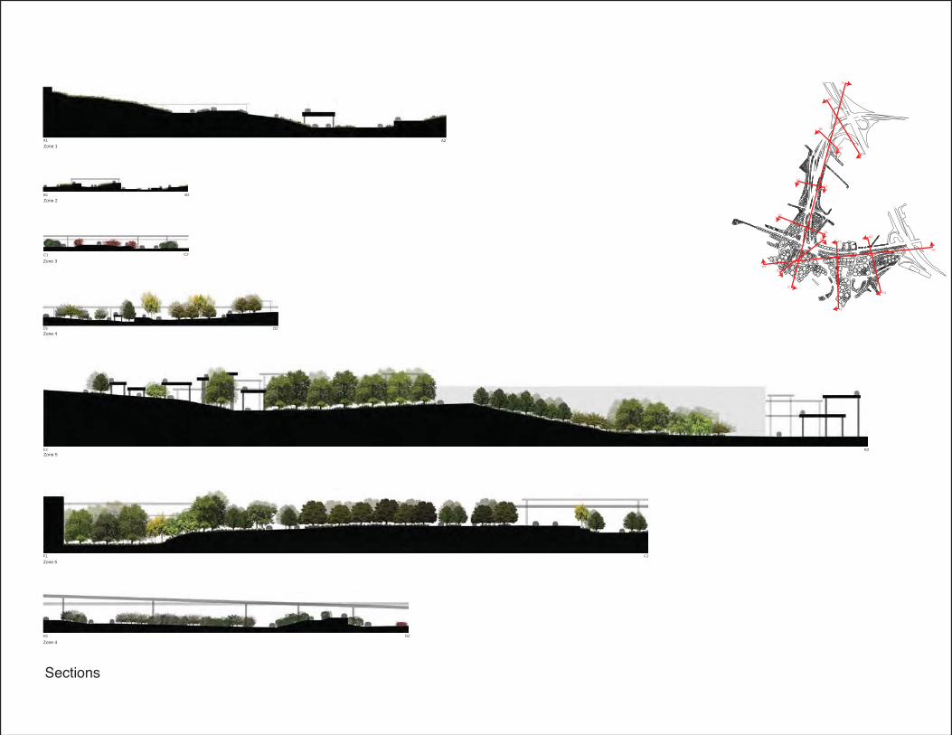
Elevated Pedestrian Pathway Vehicular Pathway and Buffers High Speed Pedestrian Pathway Low Speed Pedestrian Pathway
Sections
2A
1A
3A
3B2A
2B
Sections3A 3B
1B1A2A 2B
Don River Park ProjectLAN2013Y - Design Studio 3Fall 2009
The Don River Park is an 18 acre site, which fl anks the eastern boundary of the West Don Lands, and is situated along a critical fl ood zone along the lower Don River. As part of the fl ood control program, the site features an engineered berm, which was incorporated into the design concept.
The curvature of the berm was formed using the prevailing wind directions on the site. The slopes along the curvers were designed to direct the water fl ow on the site towards the natural low points.
THe design concept also calls for a transition of social energy going from low to high as you travel south within the site. The northern section of the park features a vegetative zone. The middle section is designed to form a large open space for casual activities or social gatherings. Since the southern end of the park is adjacent to a proposed school site, this section is dedicated as a sports fi eld site. Additionally, the berm will be terraced along the curves which face both the open green space and sports fi elds. This provides areas for casual seating and allows users to have views on the activities below.
The western edge of the berm will be heavily vegetated in order to decrease runoff and help stabilized soils during a rainfall or fl ood.
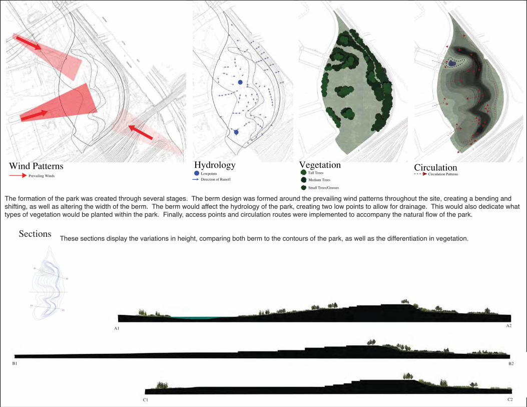
The formation of the park was created through several stages. The berm design was formed around the prevailing wind patterns throughout the site, creating a bending and shifting, as well as altering the width of the berm. The berm would affect the hydrology of the park, creating two low points to allow for drainage. This would also dedicate what types of vegetation would be planted within the park. Finally, access points and circulation routes were implemented to accompany the natural fl ow of the park.
These sections display the variations in height, comparing both berm to the contours of the park, as well as the differentiation in vegetation.

7977979779799.9999.9 999999
These images display the early stages of the parks development, and highlights the formation of the berm, and the dramatic contoured steps within the berm. The top image displays the sports fi eld along the southern edge of the park, while the lower image displays the low energy part of the northern edge of the park
0.5
1.0
1.52.0
2.53.0
3.5
4.0

Fractured Landscapes_Infrastructure LifecyclesLAN1012Y - Design Studio 2Winter 2009
Often times design concepts fail to consider the life cycle of their developments, and what happens when infrastructure becomes obsolete. Using Toronto’s Pearson International Airport as a test-site, Fractured Landscapes explores the lifecycle and processes following the decomissioning of local and major airports and their associated road networks.
The goal was to plan for the next life of the infrastructure during its current operations. The concept was to create a simple intervention through the use of planting to begin to establish grown and habitat, giving the site a head start on its eventual evolution. A vegetative corridor/gateway, was implemented in the intersitial highway spaces to mitigate the negative effects of the highway and create a connection between the fractured landscapes. This corridor is made up of fi ve different ecological communities, each increasing in height on approach to the terminal. The vegetation in the corridor becomes denser as the road narrows, acting as both a way fi nding system and a method of traffi c calming. As the plantings mature, a natural succession will take hold, continuing the evolution of the site. When roads become unnecessary due to the decline of the automobile traffi c, a modular planting system would be used to assist in the green takeover of the highway landscape. This system will bridge the fractured green spaces between roadways, creating a continuous green connections throughout the site. At the time of the decommissioning of Pearson International Airport, years from now, the vegetation creates a living/green blanket over the surroundings and seamlessly transitions to a public green space.

Pearson International Airport_2109

The site is a common result of our car-based culture. Highways chaotically rise, turn and weave around each other. They are placeless space, the same scenario plays out across North America. The reliance on the automobile is being called into question. As new alternatives become more accessible, the need for highway networks of this nature will decline. This forces us to pose the question, what becomes of this infrastructure once its life comes to an end?
highway 409_airport road interchange_terminal one
highway 409_airport road interchange
Fractured Landscape_Infrastructure Lifecycles

upper level highway
mid level highway
at grade highway
watershed boundary
The main strategy to creating the design was to examine the road network in terms of both is horizontal conditions, and its vertical characteristics. Horizontally, the intertwining road network which leads in and out of the airport creates over a hundred of small intertial spaces. By examining each of these smaller spaces in terms of its drainage, soil type, relation to the highway, elevation, sun exposure, etc, it allowed for the creation of an appropriate plant list. For the vertical characteristics of the site, the road network was seperated based on its height above ground level. By identifying the elevation changes of the roadways, it would help identify locations for different types of vegetation.

cfcgrswc
1
2
3
4
5
Zone 1 - tallgrass savannah_big blue stem_little blue stem_indian grass
Zone 2 - open bluff_coltsfoot_canada goldenrod_sweet white clover
Zone 3 - cultural thicket_serviceberry_x148_chokecherry_x92_sumac_x336_gray dogwood_x122
Zone 4 - transitional area_russian olive_x128_red cedar_x249_cockspur hawthorn_x22
Zone 5 - moist lowland deciduous forest_white birch_x130_sycamore_x13_red maple_x142_basswood_x12_green ash_x25_willow_x5_black walnut_x18_white elm_x16
A1 A2
B1 B2
C1 C2
D1 D2
E1 E2
F1 F2
G1 G2
Sections1:1000
A1
A2
B2
B1
C2
C1
D1
D2
E1
E2
F1
F2G2
G1
H1
H2
I1
I2
Zone 1
Zone 2
Zone 3
Zone 4
Zone 5
Zone 5
Zone 4
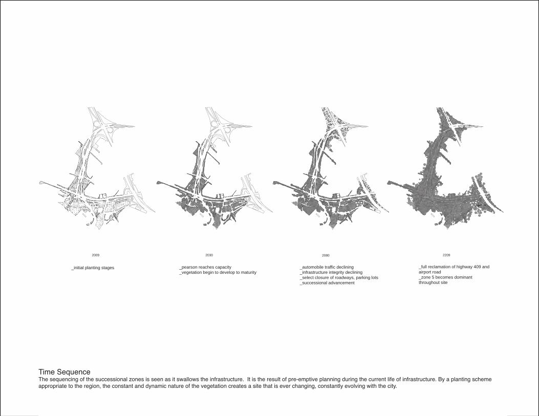
Time SequenceThe sequencing of the successional zones is seen as it swallows the infrastructure. It is the result of pre-emptive planning during the current life of infrastructure. By a planting scheme appropriate to the region, the constant and dynamic nature of the vegetation creates a site that is ever changing, constantly evolving with the city.
2009 2030 2080 2209
_initial planting stages _pearson reaches capacity_vegetation begin to develop to maturity
_automobile traffic declining_infrastructure integrity declining_select closure of roadways, parking lots_successional advancement
_full reclamation of highway 409 and airport road_zone 5 becomes dominant throughout site

Before Before
BeforeBefore
After After
AfterAfter
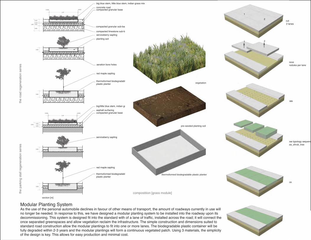
remove
aerate
chose typology sequencgrass_shrub_tree
2 modules per lane
place
2
2
1
1
cut2 lanes
the
road
reg
ener
atio
n se
ries
the
park
ing
stal
l reg
ener
atio
n se
ries
0.55
0.35
2.47
0.25
1.000.100.20
0.45
0.0150.015concrete road
big blue stem, little blue stem, indian grass mix
compacted granular base
compacted granular sub-base
compacted limestone sub-base
planting soil
serviceberry sapling
red maple sapling
aeration bore holes
thermoformed biodegradableplastic planter
thermoformed biodegradable plastic planter
section [m]
0.55
0.40
0.40
510.0510.0
0.20
0.20
2.47
asphalt surfacing
big/little blue stem, indian grass mix
compacted granular base
serviceberry sapling
red maple sapling
Modular Planting SystemAs the use of the personal automobile declines in favour of other means of transport, the amount of roadways currently in use will no longer be needed. In response to this, we have designed a modular planting system to be installed into the roadway upon its decommissioning. This system is designed fit into the standard with of a lane of traffic, installed across the road; it will connect the once separated greenspaces and allow vegetation reclaim the infrastructure. The simple construction and dimensions suited to standard road construction allow the modular plantings to fit into one or more lanes. The biodegradable plastic container will be fully degraded within 2-3 years and the modular plantings will form a continuous vegetated patch. Using 3 materials, the simplicity of the design is key. This allows for easy production and minimal cost.
compostition [grass module]
thermoformed biodegradable plastic planter
pre-seeded planting soil
vegetation

Mixed Media
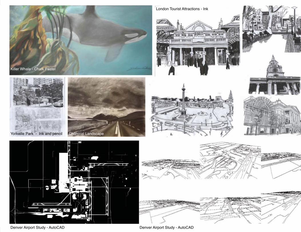
Killer Whale - Chalk Pastel
Yorkville Park - Ink and pencil
Denver Airport Study - AutoCAD Denver Airport Study - AutoCAD
Charcoal Landscape
London Tourist Attractions - Ink