july 2005 volume no. 7 - electrostatic precipitator newsletters/july 2005... · 1 july 2005 volume...
TRANSCRIPT
July 2005 Volume No. 7
STORM TECHNOLOGIES, INC. 411 North Depot Street PO Box 429
www.stormeng.com Albemarle, NC 28002
Phone: (704) 983-2040, Fax: (704) 982-9657
1
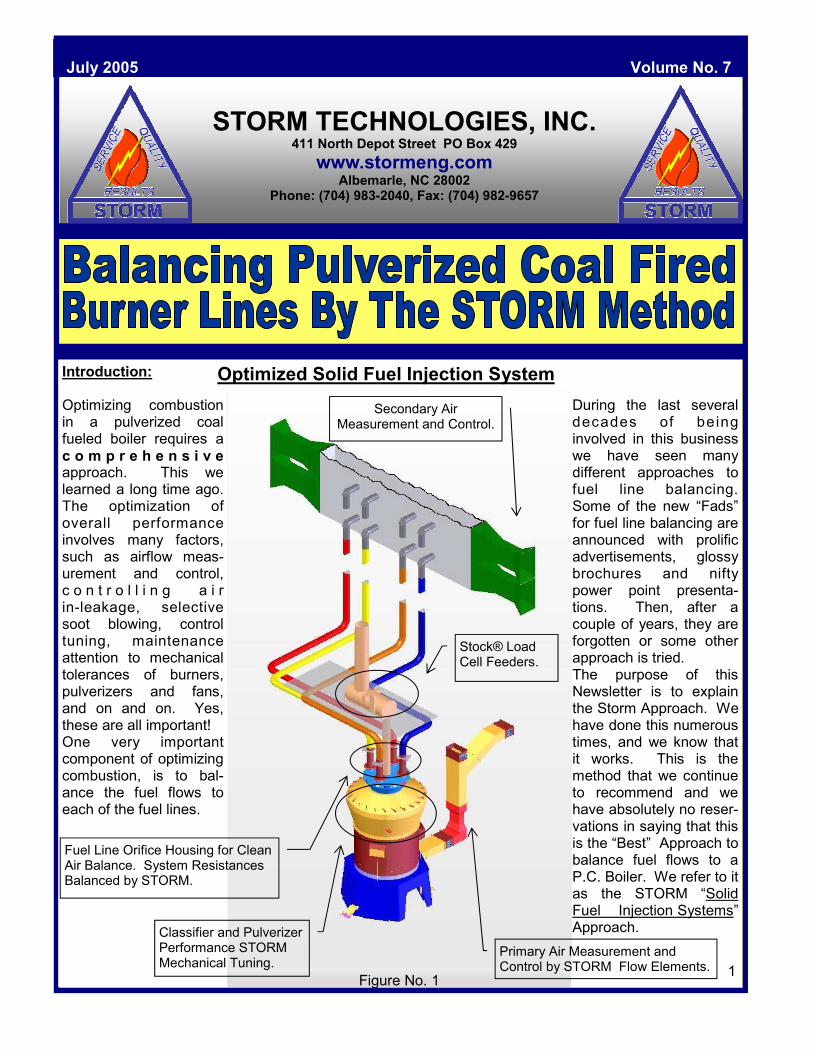
Introduction: Optimizing combustion in a pulverized coal fueled boiler requires a c o m p r e h e n s i v e approach. This we learned a long time ago. The optimization of overall performance involves many factors, such as airflow meas-urement and control, c o n t r o l l i n g a i r in-leakage, selective soot blowing, control tuning, maintenance attention to mechanical tolerances of burners, pulverizers and fans, and on and on. Yes, these are all important! One very important component of optimizing combustion, is to bal-ance the fuel flows to each of the fuel lines.
Optimized Solid Fuel Injection System
1
During the last several decades of being involved in this business we have seen many different approaches to fuel line balancing. Some of the new “Fads” for fuel line balancing are announced with prolific advertisements, glossy brochures and nifty power point presenta-tions. Then, after a couple of years, they are forgotten or some other approach is tried. The purpose of this Newsletter is to explain the Storm Approach. We have done this numerous times, and we know that it works. This is the method that we continue to recommend and we have absolutely no reser-vations in saying that this is the “Best” Approach to balance fuel flows to a P.C. Boiler. We refer to it as the STORM “Solid Fuel Injection Systems” Approach.
Stock® Load Cell Feeders.
Fuel Line Orifice Housing for Clean Air Balance. System Resistances Balanced by STORM.
Secondary Air Measurement and Control.
1 Figure No. 1
Primary Air Measurement and Control by STORM Flow Elements.
Classifier and Pulverizer Performance STORM Mechanical Tuning.
Just as a highly tuned eight cylinder high performance engine which precisely measures fuel/air delivered to each cylinder, it is our approach to achieve similar precision to each of the eight burners supplied by one coal pulverizer. And when a boiler has forty-eight burners, we do our level Best to achieve 1/48th of the fuel to each of the (48) burners. Here is the STORM Recommended Approach to balancing fuel lines. For Best Results These Pre-Requisites Are Essential:
• Stock® gravimetric feeders of the latest microprocessor & load cell type. • Vertical spindle pulverizers with one classifier/mill. • Primary airflow measured by venturi or flow nozzle, calibrated HOT for better than
±3% accuracy/repeatability over the load range. • Burner mechanical tolerances to ±1/4” tolerances (no heat warping, coke deposits,
slagging over, etc). • Fuel line sampling connections are in vertical “upflow” lines and with at least 5
diameters of upstream straight run. • Test connections must be installed in accordance with Storm Standards. • Fuel line sampling must be completed by experienced Technicians/Engineers using
a Storm Isokinetic Coal Sampler. Please be aware that exhauster/riffle equipped mills can be balanced, and even ball tube mill equipped Boilers. However these take additional steps and some slightly different techniques. Getting to a true solid fuel injections system with known measurable fuel flows does require the foregoing pre-requisites. In our experience, when these pre-requisites are established, then the next four steps Result in predictable good success.
The Storm Four Step Technique To Balancing Fuel Flows*
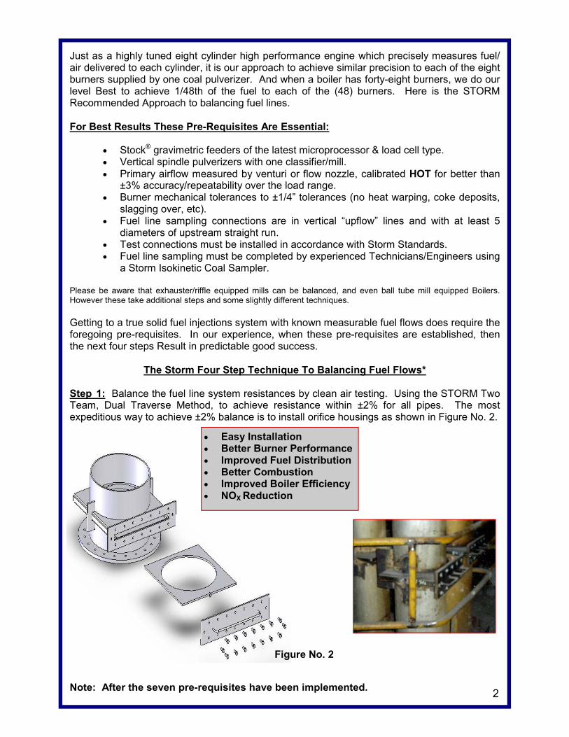
Step 1: Balance the fuel line system resistances by clean air testing. Using the STORM Two Team, Dual Traverse Method, to achieve resistance within ±2% for all pipes. The most expeditious way to achieve ±2% balance is to install orifice housings as shown in Figure No. 2.
2
Figure No. 2
• Easy Installation • Better Burner Performance • Improved Fuel Distribution • Better Combustion • Improved Boiler Efficiency • NOX Reduction
Note: After the seven pre-requisites have been implemented.
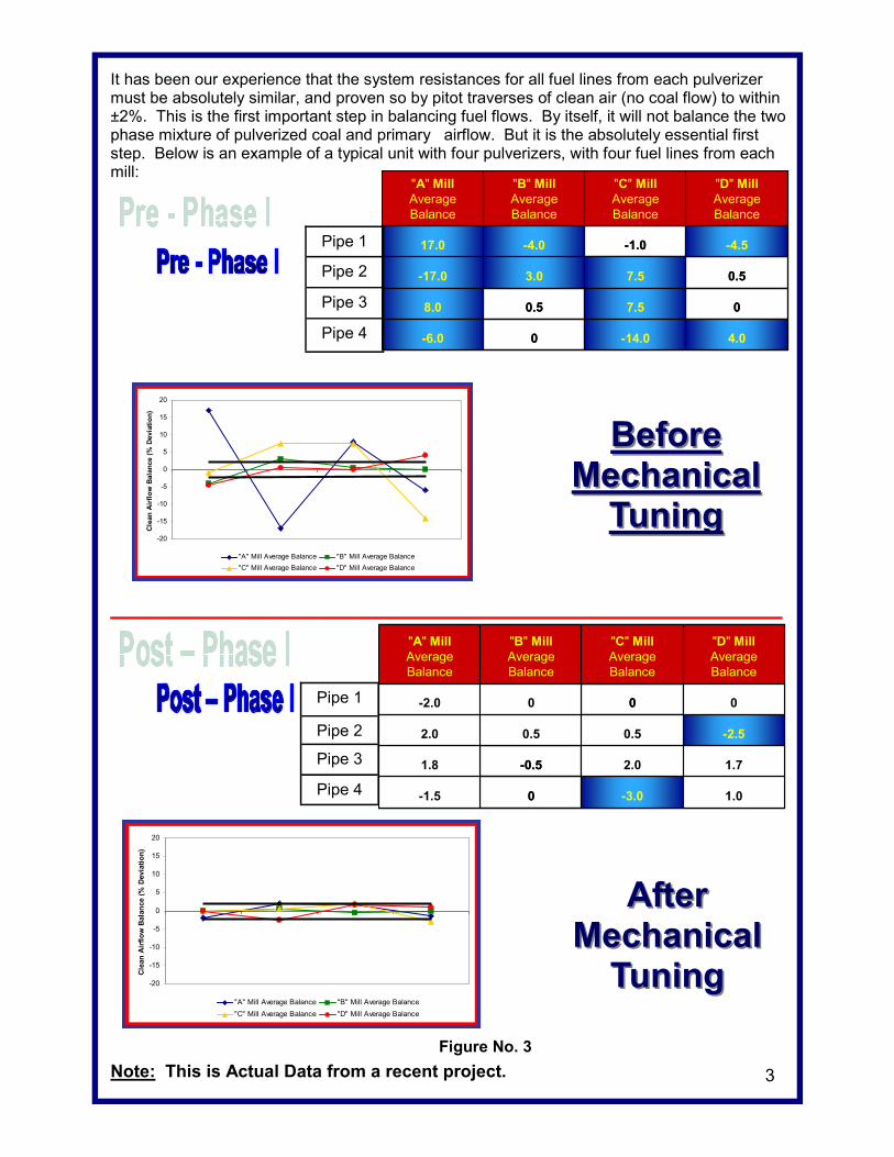
It has been our experience that the system resistances for all fuel lines from each pulverizer must be absolutely similar, and proven so by pitot traverses of clean air (no coal flow) to within ±2%. This is the first important step in balancing fuel flows. By itself, it will not balance the two phase mixture of pulverized coal and primary airflow. But it is the absolutely essential first step. Below is an example of a typical unit with four pulverizers, with four fuel lines from each mill:
___________________________________________________________
Note: This is Actual Data from a recent project.
BeforeBefore Mechanical Mechanical
Tuning Tuning
4.0-14.00-6.0
07.50.58.0
0.57.53.0-17.0
-4.5-1.0-4.017.0
"D" MillAverageBalance
"C" MillAverageBalance
"B" MillAverageBalance
"A" MillAverageBalance
4.0-14.00-6.0
07.50.58.0
0.57.53.0-17.0
-4.5-1.0-4.017.0
"D" MillAverageBalance
"C" MillAverageBalance
"B" MillAverageBalance
"A" MillAverageBalance
Pipe 1
Pipe 2
Pipe 3
Pipe 4
1.0-3.00-1.5
1.72.0-0.51.8
-2.50.50.52.0
000-2.0
"D" MillAverage Balance
"C" MillAverage Balance
"B" Mill Average Balance
"A" MillAverage Balance
1.0-3.00-1.5
1.72.0-0.51.8
-2.50.50.52.0
000-2.0
"D" MillAverage Balance
"C" MillAverage Balance
"B" Mill Average Balance
"A" MillAverage Balance
Pipe 1
Pipe 2
Pipe 3
Pipe 4
3
-20
-15
-10
-5
0
5
10
15
20
Cle
an A
irflo
w B
alan
ce (%
Dev
iatio
n)
"A" Mill Average Balance "B" Mill Average Balance"C" Mill Average Balance "D" Mill Average Balance
AfterAfter Mechanical Mechanical
TuningTuning
Figure No. 3
-20
-15
-10
-5
0
5
10
15
20
Cle
an A
irflo
w B
alan
ce (%
Dev
iatio
n)
"A" Mill Average Balance "B" Mill Average Balance"C" Mill Average Balance "D" Mill Average Balance
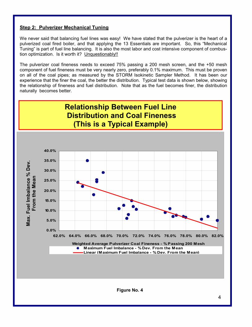
Step 2: Pulverizer Mechanical Tuning We never said that balancing fuel lines was easy! We have stated that the pulverizer is the heart of a pulverized coal fired boiler, and that applying the 13 Essentials are important. So, this “Mechanical Tuning” is part of fuel line balancing. It is also the most labor and cost intensive component of combus-tion optimization. Is it worth it? Unquestionably!! The pulverizer coal fineness needs to exceed 75% passing a 200 mesh screen, and the +50 mesh component of fuel fineness must be very nearly zero, preferably 0.1% maximum. This must be proven on all of the coal pipes; as measured by the STORM Isokinetic Sampler Method. It has been our experience that the finer the coal, the better the distribution. Typical test data is shown below, showing the relationship of fineness and fuel distribution. Note that as the fuel becomes finer, the distribution naturally becomes better.
4
Figure No. 4
Relationship Between Fuel Line Distribution and Coal Fineness
(This is a Typical Example)
0.0%
5.0%
10.0%
15.0%
20.0%
25.0%
30.0%
35.0%
40.0%
62.0% 64.0% 66.0% 68.0% 70.0% 72.0% 74.0% 76.0% 78.0% 80.0% 82.0%
Weighted Average Pulverizer Coal Fineness - % Passing 200 MeshMaximum Fuel Imbalance - % Dev. From the MeanLinear (Maximum Fuel Imbalance - % Dev. From the Mean)
Max
. Fue
l Im
bala
nce
% D
ev.
From
the
Mea
n
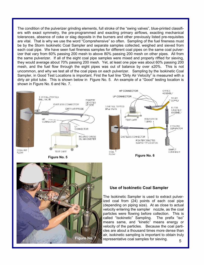
The condition of the pulverizer grinding elements, full stroke of the “swing valves”, blue-printed classifi-ers with exact symmetry, the pre-programmed and exacting primary airflows, exacting mechanical tolerances, absence of coke or slag deposits in the burners and other previously listed pre-requisites are vital. That is why we use the word “Comprehensive” so often. Sampling of the fuel fineness must be by the Storm Isokinetic Coal Sampler and separate samples collected, weighed and sieved from each coal pipe. We have seen fuel fineness samples for different coal pipes on the same coal pulver-izer that vary from 60% passing 200 mesh to above 80% passing 200 mesh on other pipes. All from the same pulverizer. If all of the eight coal pipe samples were mixed and properly riffled for sieving, they would average about 70% passing 200 mesh. Yet, at least one pipe was about 60% passing 200 mesh, and the fuel flow through the eight pipes was out of balance by over ±20%. This is not uncommon, and why we test all of the coal pipes on each pulverizer. Sampling by the Isokinetic Coal Sampler, in Good Test Locations is important. First the fuel line “Dirty Air Velocity” is measured with a dirty air pitot tube. This is shown below in Figure No. 5. An example of a “Good” testing location is shown in Figure No. 6 and No. 7.
Use of Isokinetic Coal Sampler The Isokinetic Sampler is used to extract pulver-ized coal from (24) points of each coal pipe (depending on piping size). At as close to actual velocity entering the sampler nozzle, as the coal particles were flowing before collection. This is called “Isokinetic” Sampling. The prefix “iso” means same, and “kinetic” means energy or velocity of the particles. Because the coal parti-cles are about a thousand times more dense than air, isokinetic sampling is important to obtain truly representative coal samples for sieving. 5
Figure No. 7
Figure No. 5
HP CONNECTOR
LP CONNECTOR
Figure No. 6
6
Figure No. 8
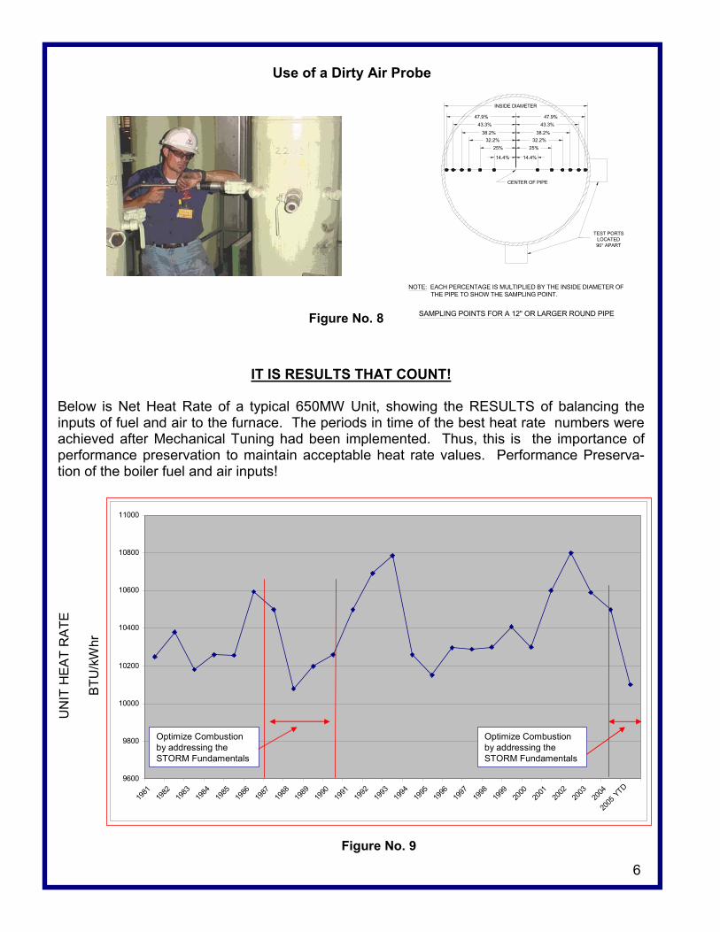
Use of a Dirty Air Probe
IT IS RESULTS THAT COUNT!
Below is Net Heat Rate of a typical 650MW Unit, showing the RESULTS of balancing the inputs of fuel and air to the furnace. The periods in time of the best heat rate numbers were achieved after Mechanical Tuning had been implemented. Thus, this is the importance of performance preservation to maintain acceptable heat rate values. Performance Preserva-tion of the boiler fuel and air inputs!
9600
9800
10000
10200
10400
10600
10800
11000
1981
1982
1983
1984
1985
1986
1987
1988
1989
1990
1991
1992
1993
1994
1995
1996
1997
1998
1999
2000
2001
2002
2003
2004
2005
YTD
Optimize Combustion by addressing the STORM Fundamentals
Optimize Combustion by addressing the STORM Fundamentals
Figure No. 9
UN
IT H
EA
T R
ATE
BTU
/kW
hr
32.2%38.2%
43.3%47.9%
INSIDE DIAMETER
25%25%32.2%
38.2%43.3%
47.9%
14.4% 14.4%
CENTER OF PIPE
NOTE: EACH PERCENTAGE IS MULTIPLIED BY THE INSIDE DIAMETER OF THE PIPE TO SHOW THE SAMPLING POINT.
SAMPLING POINTS FOR A 12" OR LARGER ROUND PIPE
TEST PORTSLOCATED90° APART
7
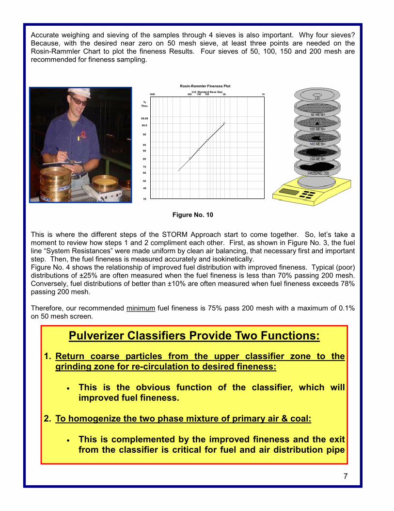
Accurate weighing and sieving of the samples through 4 sieves is also important. Why four sieves? Because, with the desired near zero on 50 mesh sieve, at least three points are needed on the Rosin-Rammler Chart to plot the fineness Results. Four sieves of 50, 100, 150 and 200 mesh are recommended for fineness sampling.
This is where the different steps of the STORM Approach start to come together. So, let’s take a moment to review how steps 1 and 2 compliment each other. First, as shown in Figure No. 3, the fuel line “System Resistances” were made uniform by clean air balancing, that necessary first and important step. Then, the fuel fineness is measured accurately and isokinetically. Figure No. 4 shows the relationship of improved fuel distribution with improved fineness. Typical (poor) distributions of ±25% are often measured when the fuel fineness is less than 70% passing 200 mesh. Conversely, fuel distributions of better than ±10% are often measured when fuel fineness exceeds 78% passing 200 mesh. Therefore, our recommended minimum fuel fineness is 75% pass 200 mesh with a maximum of 0.1% on 50 mesh screen.
Rosin-Rammler Fineness PlotU.S. Standard Sieve Size
99.99
% Thru
99.9
99
95
90
80
70
60
50
40
30
10100 501402001000
Figure No. 10
Pulverizer Classifiers Provide Two Functions:
1. Return coarse particles from the upper classifier zone to the grinding zone for re-circulation to desired fineness:
• This is the obvious function of the classifier, which will
improved fuel fineness. 2. To homogenize the two phase mixture of primary air & coal:
• This is complemented by the improved fineness and the exit from the classifier is critical for fuel and air distribution pipe
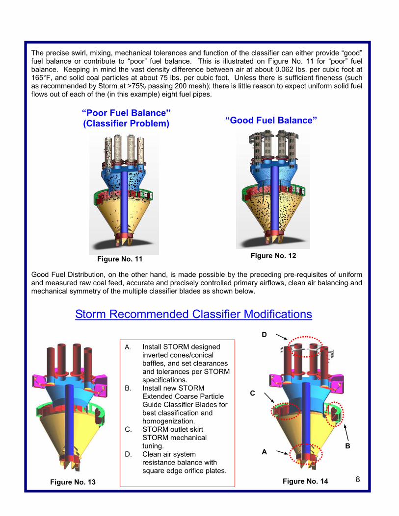
The precise swirl, mixing, mechanical tolerances and function of the classifier can either provide “good” fuel balance or contribute to “poor” fuel balance. This is illustrated on Figure No. 11 for “poor” fuel balance. Keeping in mind the vast density difference between air at about 0.062 lbs. per cubic foot at 165°F, and solid coal particles at about 75 lbs. per cubic foot. Unless there is sufficient fineness (such as recommended by Storm at >75% passing 200 mesh); there is little reason to expect uniform solid fuel flows out of each of the (in this example) eight fuel pipes. Good Fuel Distribution, on the other hand, is made possible by the preceding pre-requisites of uniform and measured raw coal feed, accurate and precisely controlled primary airflows, clean air balancing and mechanical symmetry of the multiple classifier blades as shown below.
A. Install STORM designed inverted cones/conical baffles, and set clearances and tolerances per STORM specifications.
B. Install new STORM Extended Coarse Particle Guide Classifier Blades for best classification and homogenization.
C. STORM outlet skirt STORM mechanical tuning.
D. Clean air system resistance balance with square edge orifice plates.
8
“Poor Fuel Balance” (Classifier Problem)
Figure No. 11
“Good Fuel Balance”
Figure No. 12
Figure No. 13
Storm Recommended Classifier Modifications
Figure No. 14
D
C
A B
9
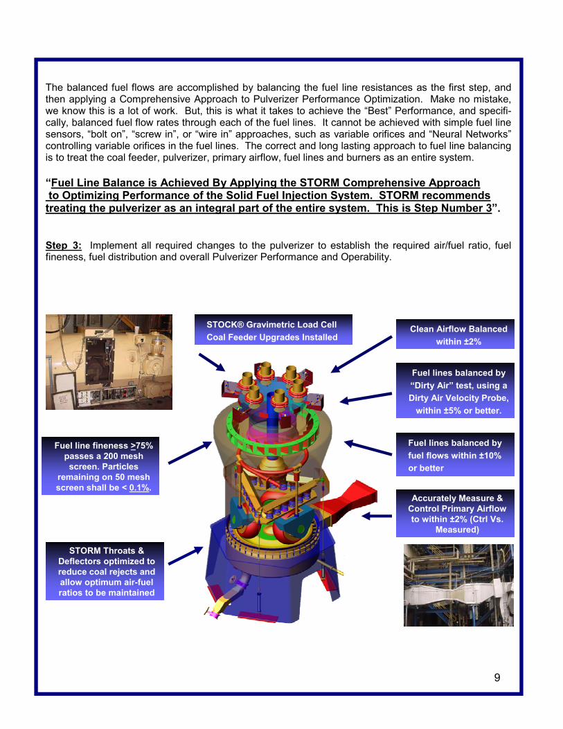
The balanced fuel flows are accomplished by balancing the fuel line resistances as the first step, and then applying a Comprehensive Approach to Pulverizer Performance Optimization. Make no mistake, we know this is a lot of work. But, this is what it takes to achieve the “Best” Performance, and specifi-cally, balanced fuel flow rates through each of the fuel lines. It cannot be achieved with simple fuel line sensors, “bolt on”, “screw in”, or “wire in” approaches, such as variable orifices and “Neural Networks” controlling variable orifices in the fuel lines. The correct and long lasting approach to fuel line balancing is to treat the coal feeder, pulverizer, primary airflow, fuel lines and burners as an entire system. “Fuel Line Balance is Achieved By Applying the STORM Comprehensive Approach to Optimizing Performance of the Solid Fuel Injection System. STORM recommends treating the pulverizer as an integral part of the entire system. This is Step Number 3”. Step 3: Implement all required changes to the pulverizer to establish the required air/fuel ratio, fuel fineness, fuel distribution and overall Pulverizer Performance and Operability.
Accurately Measure & Control Primary Airflow to within ±2% (Ctrl Vs.
Measured)
STOCK® Gravimetric Load Cell Coal Feeder Upgrades Installed
Clean Airflow Balanced within ±2%
Fuel line fineness >75% passes a 200 mesh screen. Particles
remaining on 50 mesh screen shall be < 0.1%.
Fuel lines balanced by “Dirty Air” test, using a Dirty Air Velocity Probe,
within ±5% or better.
Fuel lines balanced by fuel flows within ±10% or better
STORM Throats & Deflectors optimized to reduce coal rejects and allow optimum air-fuel ratios to be maintained
Step 4 Performance Preservation: The first three steps require a commitment of all plant O&M personnel. To be sure, getting to this point is a lot of work and has taken over a year on some plants which we have completed the full program. But, it is worth it! The benefits are significant, including:
Just the savings for three of the above: heat rate, slagging and fuels flexibility can be millions of dollars per year. Yes, achieving “Good” Results like this does take consistently applied condition based main-tenance. That is, pulverizers, fuel lines and burner maintenance should be driven by periodic fuel line testing and then maintenance driven by actual pulverizer fineness and fuel distribution; NOT by tons of coal throughput or thousands of hours of operation! Truly optimum pulverized coal fueled boiler performance can significantly improve the overall plant performance, including heat rate. This may seem abstract, but it is true and has been proven at a number of plants where the operations and maintenance commitment persisted for several years. Yes, years. Good Results by this method does take time, but the Rewards are there. Some of the case studies have been presented at ASME, PowerGen, EPRI and other technical gath-erings. Also, the importance of O&M attention to combustion as an important component of heat-rate improvement has been published in “Power” Magazine and “World Coal” magazine. Some of these presentations are available on our website at www.stormeng.com. We know this is the Best Approach to fuel line balancing, which is a large component in achieving overall “Best Possible” plant performance. A commitment to Performance Preserva-tion will lead to Improved RESULTS! If you would like more information, please give us a call or send us an email. Yours Truly,
Richard F. (Dick) Storm President/Consultant 10
1. Heat rate improvement. 7. Reduced pulverizer fires.
2. Coal rejects reduction. 8. Increased capacity factor. 3. Burner fires reduction. 9. Reduced waterwall wastage.
4. Reduced in furnace NO production. 10. Improved reliability.
5. Reduced slagging and fouling. 11. Reduced de-superheating spray water flows.
6. Improved fuels flexibility. 12. Reduced “Popcorn Ash” plugging of SCR’s.

Large Electric Utility Boiler Combustion and Performance
Optimization 2 Day Short Course
Date: August 9-10, 2005
Time: 8:00am to 5:00pm
Location: Hyatt at Southpark 5501 Carnegie Boulevard
Charlotte, NC 28209-3462
Phone: (704) 554-1234
Fax: (704) 554-8319
Storm Technologies, Inc. 411 North Depot Street
PO Box 429 Albemarle, NC 28002 Phone: (704) 983-2040
Fax: (704) 982-9657 www.stormeng.com
16 PDH’s This course is approved by the N.C and Florida boards of registration for engineers continuing professional development hours. Who has attended this course in the past and provided positive feedback? Plant engineers, results engineers, performance engineers, operation super-visors/superintendents, maintenance supervisors/superintendents, plant managers, central engineering/design engineers. What are some of the topics that are covered? • Boiler controllable heat rate factors • Applying the 13 Essentials of Optimum Combustion • Reducing NOx by the “Total Combustion Optimization Approach” • Boiler comprehensive and diagnostic testing • Boiler and combustion systems design overview of different OEM
configurations • Why some fuels are more NOx friendly than others • Why some boiler designs are more NOx or LOI forgiving • Fuel properties • Pulverizer performance improvements • Fan boosted overfire air systems for NOx reduction What are the course objectives? 1. Present a practical approach to combustion and performance
optimization with focus on the fundamentals. 2. Have each participant come away from the course with at least one
idea or concept that can be put to immediate and profitable use at their home plant
3. Provide an atmosphere of free flowing and sharing of useful technical information both between the instructor and the atten-dees, and between the short-course participants.
Instructor: Richard F. (Dick) Storm-President of Storm Technologies, Inc., a regis-tered P.E. , and with over 40 years experience in the industry. Experi-ence has been accumulated as a results engineer and start-up engineer for OEM’s and a principal engineer and a superintendent of operations for a major utility, and as a department head for a technical services department of a boiler maintenance contractor. These experiences pre-ceded the last 12 years at Storm Engineering and Associates Inc. and Storm Technologies, Inc. Therefore, the topics presented and discussed are done from a per-spective of design, best operation, maintainability, objectivity and with a practical focus on getting the most cost-effective RESULTS!
Seats Still Available—So sign-up today! For Full Registration Form Go To
www.stormeng.com
11
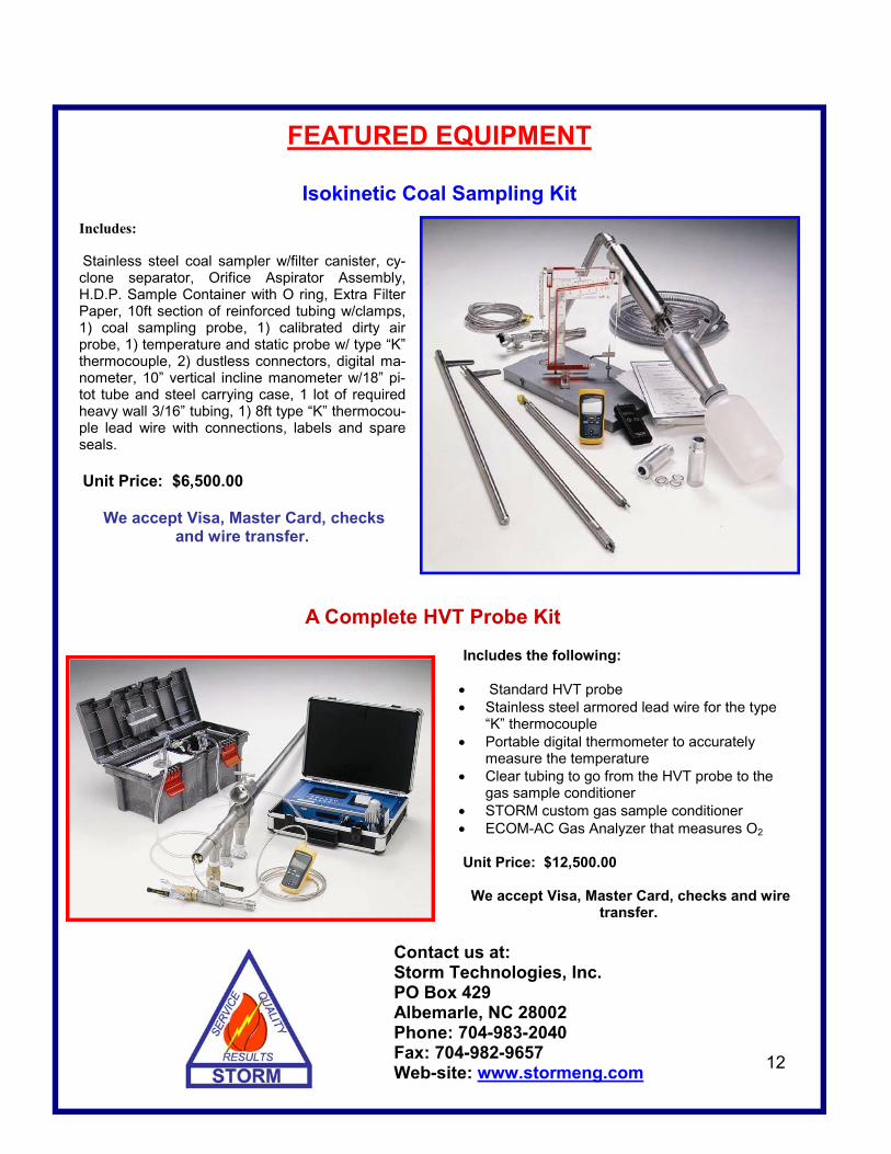
Includes: Stainless steel coal sampler w/filter canister, cy-clone separator, Orifice Aspirator Assembly, H.D.P. Sample Container with O ring, Extra Filter Paper, 10ft section of reinforced tubing w/clamps, 1) coal sampling probe, 1) calibrated dirty air probe, 1) temperature and static probe w/ type “K” thermocouple, 2) dustless connectors, digital ma-nometer, 10” vertical incline manometer w/18” pi-tot tube and steel carrying case, 1 lot of required heavy wall 3/16” tubing, 1) 8ft type “K” thermocou-ple lead wire with connections, labels and spare seals. Unit Price: $6,500.00
We accept Visa, Master Card, checks and wire transfer.
Contact us at: Storm Technologies, Inc. PO Box 429 Albemarle, NC 28002 Phone: 704-983-2040 Fax: 704-982-9657 Web-site: www.stormeng.com
Includes the following: • Standard HVT probe • Stainless steel armored lead wire for the type
“K” thermocouple • Portable digital thermometer to accurately
measure the temperature • Clear tubing to go from the HVT probe to the
gas sample conditioner • STORM custom gas sample conditioner • ECOM-AC Gas Analyzer that measures O2 Unit Price: $12,500.00
We accept Visa, Master Card, checks and wire transfer.
Isokinetic Coal Sampling Kit
A Complete HVT Probe Kit
12
FEATURED EQUIPMENT