journal supervisory
DESCRIPTION
In this research, a Fuzzy, classical (PID) and a combination of them, as a fuzzy-classical control method, are used in designing of the longitudinal motion controller for an aircraft.TRANSCRIPT
1
Comparison the Performance of an
Automatic Landing System Using Fuzzy,
Classical and Supervisory Controllers
Masoud Shakeri
Department of Electrical Engineering, Malek Ashtar University of Technology, Tehran, Iran ([email protected])
Mohammad Ali Shahi Ashtiani
Assistant Professor Department of Electrical Engineering, Malek Ashtar University of
Technology, Tehran, Iran ([email protected])
Seyyed Hossein Sadati
Assistant Professor, Department of Electrical Engineering, Malek Ashtar University of
Technology, Tehran, Iran ([email protected])
Abstract
In this research, a Fuzzy, classical (PID) and a combination of them, as a fuzzy-classical
control method, are used in designing of the longitudinal motion controller for an aircraft.
The main objectives of each of these controllers are to reduce the vertical velocity and
altitude of the aircraft in glide slope and flare phases. In fact, each longitudinal controller
consists of two controllers. The first controller produces required pitch angle for aircraft
guidance to the specified trajectory, and the second one will produce elevator deflection for
aircraft rotation to the desired path. These controllers have proper performance in landing
phase but they are not more stable in presence of some wind disturbances. Therefore, by
adding an appropriate supervisory controller, the stability of the system against turbulence
will be increased. Simulation results show that the supervisory controller can successfully
raise the safety envelope to include more hostile environments such as wind disturbances.
Keywords—Automatic landing systems, Classical Control, fuzzy Control, supervisory
Control
1. INTRODUCTION After the realization of flight dream, flight safety was the most important issue for aircraft
designers. In this case, minimizing the human factors and moving toward automatic control
systems is an effective step in improving flight safety.
According to the reference released by Boeing, 47% of the aircraft crashes happened in final
approach and landing phase. On the other hand, 76% of all incidences were due to human factors
and 5% related to sudden changes in atmospheric conditions [1].
Considering the above points mentioned:
1. In terms of safety, the landing phase is the most critical phase of flight.
2. In terms of workload, this phase has a high percentage of total flight operations.
The earliest ILS systems were designed in 1943 and today have considerably progressed.
Although the ILS equipment provide facilities for pilots in the landing phase, but they are not fully
automated. Automatic landing systems include three sub-controllers:
1. Approach angle control systems
2. Flare phase control systems
3. Lateral-directional control systems
In this research, only the first two systems will be investigated.
Comparison the Performance of an Automatic Landing System Using Fuzzy, Classical and Supervisory Controllers
Comparison the Performance of an Automatic Landing System Using Fuzzy, Classical and Supervisory Controllers
2
The first automatic landing system (ALS)1 developed, in the early years of making ILS, in
England. Early systems were only able to control the approach phase while newer models are also
able to control the Aircraft in next phases [2].
In designing of the aircraft automatic landing system, it is very important to determine the desired
trajectory from the beginning of landing until touching down the runway.
Intelligent controls using neural networks and fuzzy logic in several applications such as auto pilot
[3], process control [4] and robotics [5] have been studied. In recent years, control law design based on fuzzy logic had significant progress in industrial
applications, especially in cases with uncertainties presence, in wide range of conditions [6]. In [7]
the fuzzy-neural controller was used for landing control in a commercial airliner. The controller
had been tested as well, in the some various disturbances. In later works, genetic algorithm was
used in order to find the fuzzy–neural controller gains [8].
In this research a longitudinal controller is designed to control the landing phase of Boeing 747
airplane. In The designed control system a combination of fuzzy and classical methods is used to
control the aircraft height and descent rate, in Flare and Glide phases.
This paper contains the following sections. First, the equations of motion of an aircraft and landing
phases are studied. Then, a reference model will be suggested for adjusting the height of the
aircraft. Then, fuzzy and classical controls are used in order to design the best longitudinal
controller. After that, supervisory controller will increase the stability of the auto land systems
against sudden weather conditions. Finally, simulation results will be presented.
2. EQUATIONS OF MOTION The equations of motion are obtained with the assumption of a rigid aircraft. These equations
are coupled and nonlinear. Equations can be linear, with assuming a constant speed, symmetric
flight and low speed disturbances compare with aircraft flight speed in landing phase. Here, using
the theory of small perturbation, the equations have been linear. Matrix of linear equations for
longitudinal variables has been described below [9].
0.021 0.122 0.000 0.322 0.01 1.0
0.209 0.530 2.210 0.000 0.064 0.044
0.017 0.164 0.412 0.000 0.378 0.544
0.000 0.000 1.000 0.000 0.000 0.000
E
T
u u
w w
q q
(1)
Where
q = pitch rate, θ = pitch angle, E = elevator deflection, T = throttle deflection; u and w are
respectively, the forward and downward velocity in the body coordinate system and the units are
in feet, seconds and radians.
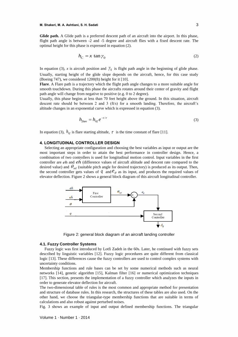
3. DESIRED TRAJECTORY IN LANDING PHASE Figure 1 shows a simple pattern of landing phases. The desired landing trajectory for an aircraft
is mainly divided into glide path and flare.
Figure 1: General view of aircraft landing trajectory
1 Instrument Landing System
M. Shakeri, M. A. Ashtiani, S. H. Sadati
Volume 1 · Number 1 · 2014
3
Glide path. A Glide path is a preferred descent path of an aircraft into the airport. In this phase,
flight path angle is between -2 and -5 degree and aircraft flies with a fixed descent rate. The
optimal height for this phase is expressed in equation (2).
0tan
Ch x (2)
In equation (3), x is aircraft position and 0 is flight path angle in the beginning of glide phase.
Usually, starting height of the glide slope depends on the aircraft, hence, for this case study
(Boeing 747), we considered 1200(ft) height for it [10].
Flare. A Flare path is a trajectory which the flight path angle changes to a more suitable angle for
smooth touchdown. During this phase the aircrafts rotates around their center of gravity and flight
path angle will change from negative to positive (e.g. 0 to 2 degree).
Usually, this phase begins at less than 70 feet height above the ground. In this situation, aircraft
descent rate should be between 2 and 3 (ft/s) for a smooth landing. Therefore, the aircraft’s
altitude changes in an exponential curve which is expressed in equation (3).
/
0
t
flare fh h e (3)
In equation (3), 0fh is flare starting altitude, is the time constant of flare [11].
4. LONGITUDINAL CONTROLLER DESIGN
Selecting an appropriate configuration and choosing the best variables as input or output are the
most important steps in order to attain the best performance in controller design. Hence, a
combination of two controllers is used for longitudinal motion control. Input variables in the first
controller are eh and eh (difference values of aircraft altitude and descent rate compared to the
desired value) and ref (suitable pitch angle for desired trajectory) is produced as its output. Then,
the second controller gets values of q and e as its input, and produces the required values of
elevator deflection. Figure 2 shows a general block diagram of this aircraft longitudinal controller.
Figure 2: general block diagram of an aircraft landing controller
4.1. Fuzzy Controller Systems
Fuzzy logic was first introduced by Lotfi Zadeh in the 60s. Later, he continued with fuzzy sets
described by linguistic variables [12]. Fuzzy logic procedures are quite different from classical
logic [13]. These differences cause the fuzzy controllers are used to control complex systems with
uncertainty conditions.
Membership functions and rule bases can be set by some numerical methods such as neural
networks [14], genetic algorithm [15], Kalman filter [16] or numerical optimization techniques
[17]. This section, presents the implementation of a fuzzy controller which analyzes the inputs in
order to generate elevator deflection for aircraft.
The two-dimensional table of rules is the most common and appropriate method for presentation
and structure of database rules. In this research, the structures of these tables are also used. On the
other hand, we choose the triangular-type membership functions that are suitable in terms of
calculations and also robust against perturbed noises.
Fig. 3 shows an example of input and output defined membership functions. The triangular
Comparison the Performance of an Automatic Landing System Using Fuzzy, Classical and Supervisory Controllers
Comparison the Performance of an Automatic Landing System Using Fuzzy, Classical and Supervisory Controllers
4
membership functions, defined for all longitudinal variables, are completely symmetrical.
Figure 3 : An example for the membership functions
Interpretation of some of the linguistic variables for input and output are defined as:
PM = Positive Medium PL = Positive Large
PS = Positive Short ZE = Zero
NM = Negative Large NL = Negative Medium
Table 1 and table 2, respectively, show defined fuzzy rules for first and second fuzzy controller.
The first controller outputs equal to a proper pitch angle and the second controller outputs are the
elevator deflection. In this research, the fuzzy logic membership functions and its associated rule
base are determined heuristically. The crisp FLC outputs are also determined by the centroid
method.
Table 1: Fuzzy rules for the first controller.
PL
PM
PS
ZE
NS
NM
NL
eh
ehdot
PL PL PM PS ZE NS NS PL PL PM PS ZE NS NS NM PM
PM PS ZE NS NS NM NM PS PS ZE NS NS NM NM NM ZE ZE NS NS NM NM NM NL NS NS NS NM NM NM NL NL NM
NS NM NM NM NL NL NL NL
Table 2: Fuzzy rules for the second controller.
PL
PS
ZE
NS
NL
eθ
q
ZE PS PL PL PL PL
NS ZE PS PL PL PS
NL NS ZE PS PL ZE
NL NL NS ZE PS NS
NL NL NL NS ZE NL
M. Shakeri, M. A. Ashtiani, S. H. Sadati
Volume 1 · Number 1 · 2014
5
4.2. Classical Controller Design
Classical controls are the simplest method for designing an aircraft controller by using linear
equations of the plant. For linearization, a series of simplifying assumptions are regarded to obtain
simple mathematical equations. These simplifications lead to a great difference between the
considered and actual conditions. Therefore, their usage is not applicable for all real conditions.
However, the classical controllers are used in most industrial systems because of their speed and
simplicity [18].
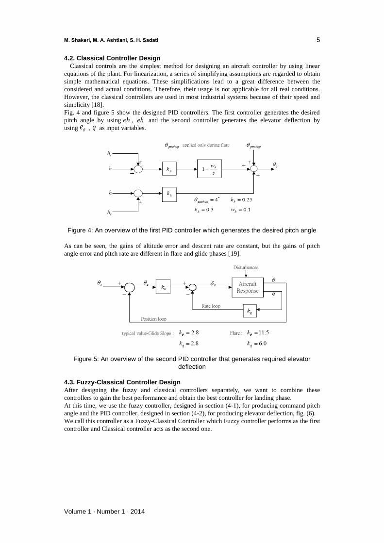
Fig. 4 and figure 5 show the designed PID controllers. The first controller generates the desired
pitch angle by using eh , eh and the second controller generates the elevator deflection by
using e , q as input variables.
Figure 4: An overview of the first PID controller which generates the desired pitch angle
As can be seen, the gains of altitude error and descent rate are constant, but the gains of pitch
angle error and pitch rate are different in flare and glide phases [19].
Figure 5: An overview of the second PID controller that generates required elevator
deflection
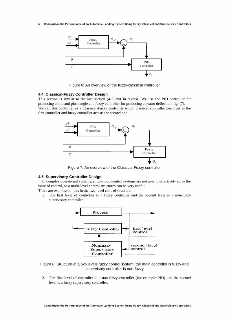
4.3. Fuzzy-Classical Controller Design
After designing the fuzzy and classical controllers separately, we want to combine these
controllers to gain the best performance and obtain the best controller for landing phase.
At this time, we use the fuzzy controller, designed in section (4-1), for producing command pitch
angle and the PID controller, designed in section (4-2), for producing elevator deflection, fig. (6).
We call this controller as a Fuzzy-Classical Controller which Fuzzy controller performs as the first
controller and Classical controller acts as the second one.
Comparison the Performance of an Automatic Landing System Using Fuzzy, Classical and Supervisory Controllers
Comparison the Performance of an Automatic Landing System Using Fuzzy, Classical and Supervisory Controllers
6
Figure 6: An overview of the fuzzy-classical controller
4.4. Classical-Fuzzy Controller Design
This section is similar to the last section (4-3) but in reverse. We use the PID controller for
producing command pitch angle and fuzzy controller for producing elevator deflection, fig. (7).
We call this controller as a Classical-Fuzzy controller which classical controller performs as the
first controller and fuzzy controller acts as the second one.
Figure 7: An overview of the Classical-Fuzzy controller
4.5. Supervisory Controller Design In complex operational systems, single-loop control systems are not able to effectively solve the
issue of control, so a multi-level control structures can be very useful.
There are two possibilities in the two-level control structure:
1. The first level of controller is a fuzzy controller and the second level is a non-fuzzy
supervisory controller.
Figure 8: Structure of a two levels fuzzy control system, the main controller is fuzzy and
supervisory controller is non-fuzzy
2. The first level of controller is a non-fuzzy controller (for example PID) and the second
level is a fuzzy supervisory controller.
M. Shakeri, M. A. Ashtiani, S. H. Sadati
Volume 1 · Number 1 · 2014
7
Figure 9: Structure of a two levels fuzzy control system, the main controller is non-fuzzy
and supervisory controller is fuzzy
In this research, the first kind of supervisory controller is considered. On the other hand, as will be
shown, the fuzzy-classical controller has the best performance in landing phase, hence for this
case, the first level controller is fuzzy and the second-level controller is classic.
Figure 10 shows the inside of the supervisory controller. As can be seen, the fuzzy-classical
controller is used for the process and a non-fuzzy (PID) controller supervises of the performance
of fuzzy controller, which produces the value of the command pitch angle.
Figure 10: Structure of a two levels fuzzy supervisory control system
4.5.1. Obtaining the Control Law Equation (4) shows the general form for obtaining the control law.
*( ) ( )fuzz su u X I u X (4)
1( ) ( )[ ( ( ) ]T u T
s fuzz
L
u X sign X pb f K X u Xg
(5)
The coefficients, in equation (5), can be obtained in [20]. If xX M then * 1I else
* 0I . In fact, *I is a switching function. For elimination of chattering, *I is considered as:
*
0
1
x
x
x
X a
X aI a X M
M a
X M
(6)
Comparison the Performance of an Automatic Landing System Using Fuzzy, Classical and Supervisory Controllers
Comparison the Performance of an Automatic Landing System Using Fuzzy, Classical and Supervisory Controllers
8
That (0, )xa M and is obtained by control designer [20]. The value of parameters is considered
as 35( ), 10xM ft a .
It means, if eh would be more than 35 (ft) then *I function operates in control loop and affects on
the value of command pitch angle (C ).
Fuzzy-Classical controllers are able to properly control the aircraft in landing phase by itself [21].
Therefore, the fuzzy-supervisory controller is designed to control aircraft in bad weather
conditions, especially in sudden gusts that are mentioned below.
4.6. Gust Model
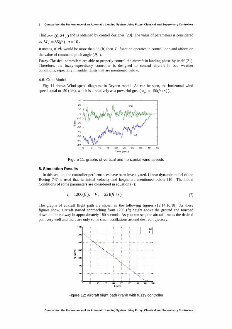
Fig. 11 shows Wind speed diagrams in Dryden model. As can be seen, the horizontal wind
speed equal to -50 (ft/s), which is a relatively as a powerful gust ( gcu 50( / )ft s ).
Figure 11: graphs of vertical and horizontal wind speeds
5. Simulation Results
In this section, the controller performances have been investigated. Linear dynamic model of the
Boeing 747 is used that its initial velocity and height are mentioned below [10]. The initial
Conditions of some parameters are considered in equation (7):
01200( ), 221( / )h ft V ft s (7)
The graphs of aircraft flight path are shown in the following figures (12,14,16,18). As these
figures show, aircraft started approaching from 1200 (ft) height above the ground and touched
down on the runway in approximately 180 seconds. As you can see, the aircraft tracks the desired
path very well and there are only some small oscillations around desired trajectory.
Figure 12: aircraft flight path graph with fuzzy controller
M. Shakeri, M. A. Ashtiani, S. H. Sadati
Volume 1 · Number 1 · 2014
9
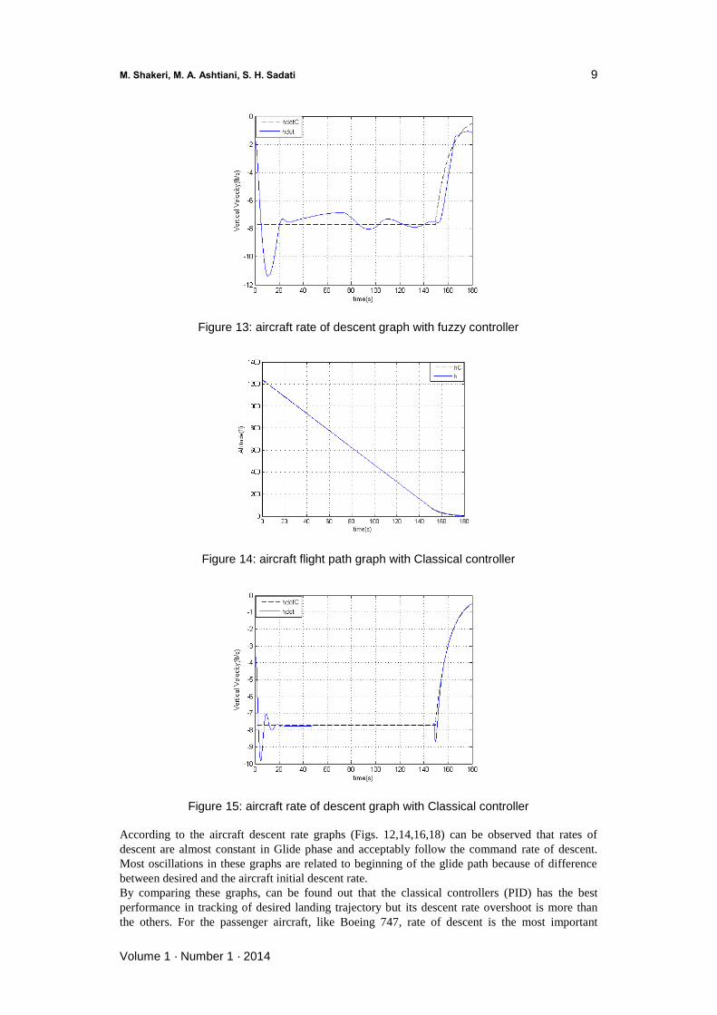
Figure 13: aircraft rate of descent graph with fuzzy controller
Figure 14: aircraft flight path graph with Classical controller
Figure 15: aircraft rate of descent graph with Classical controller
According to the aircraft descent rate graphs (Figs. 12,14,16,18) can be observed that rates of
descent are almost constant in Glide phase and acceptably follow the command rate of descent.
Most oscillations in these graphs are related to beginning of the glide path because of difference
between desired and the aircraft initial descent rate.
By comparing these graphs, can be found out that the classical controllers (PID) has the best
performance in tracking of desired landing trajectory but its descent rate overshoot is more than
the others. For the passenger aircraft, like Boeing 747, rate of descent is the most important
Comparison the Performance of an Automatic Landing System Using Fuzzy, Classical and Supervisory Controllers
Comparison the Performance of an Automatic Landing System Using Fuzzy, Classical and Supervisory Controllers
10
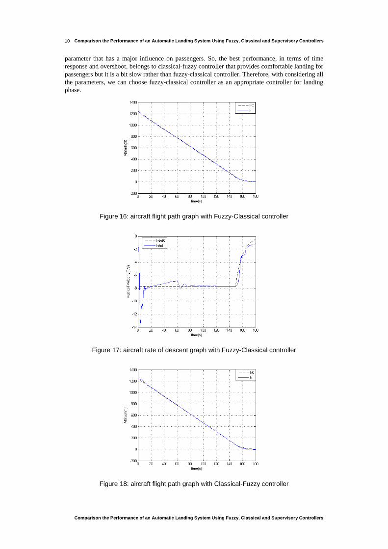
parameter that has a major influence on passengers. So, the best performance, in terms of time
response and overshoot, belongs to classical-fuzzy controller that provides comfortable landing for
passengers but it is a bit slow rather than fuzzy-classical controller. Therefore, with considering all
the parameters, we can choose fuzzy-classical controller as an appropriate controller for landing
phase.
Figure 16: aircraft flight path graph with Fuzzy-Classical controller
Figure 17: aircraft rate of descent graph with Fuzzy-Classical controller
Figure 18: aircraft flight path graph with Classical-Fuzzy controller
M. Shakeri, M. A. Ashtiani, S. H. Sadati
Volume 1 · Number 1 · 2014
11
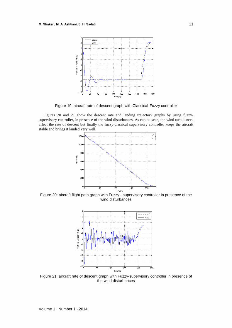
Figure 19: aircraft rate of descent graph with Classical-Fuzzy controller
Figures 20 and 21 show the descent rate and landing trajectory graphs by using fuzzy-
supervisory controller, in presence of the wind disturbances. As can be seen, the wind turbulences
affect the rate of descent but finally the fuzzy-classical supervisory controller keeps the aircraft
stable and brings it landed very well.
Figure 20: aircraft flight path graph with Fuzzy - supervisory controller in presence of the
wind disturbances
Figure 21: aircraft rate of descent graph with Fuzzy-supervisory controller in presence of
the wind disturbances
Comparison the Performance of an Automatic Landing System Using Fuzzy, Classical and Supervisory Controllers
Comparison the Performance of an Automatic Landing System Using Fuzzy, Classical and Supervisory Controllers
12
6. Conclusion
The main purpose of this paper is to compare the performance of the fuzzy, classical and the
combined classical-fuzzy and fuzzy–classical controller performance in landing phase.
Simulation results show that classical controller tracks commands, have sent from the runway,
very well. So we can conclude that classical controller, because of its high speed command
tracking, is the best choice to control different motions of UAV.
Considering the overshoot of the descent rate shows that the classical-fuzzy controllers have the
best performance in landing phase.
The controller stability against wind disturbance was not very well [22]. Therefore, the fuzzy–
Supervisory controllers has been designed that resulting graphs show the proper performance of
this controllers in the bad weather conditions.
In future work, improving the range of input and output membership functions, in classical-
fuzzy controller, and also adaptive-fuzzy controller for improving the aircraft response and
reliability against sudden and stronger wind disturbance will be considered.
REFERENCES
[1] Boeing. Publication. Statistical Summary of commercial jet Airplane Accidents, Worldwide Operations 1959-1999.
[2] Mclean, D., Automatic Flight Control Systems, Prentice Hall, 1990.
[3] J. Juang and K. Cheng, ―Wind disturbances encountered during controlled landings using neural network approaches,‖
Proc. of the IEEE Int. Conf. on Control Applications, pp. 835-840, 2001.
[4] L. McLauchlan and M. Mehrubeoglu, ―Neural network internal model process control,‖ Proc. of SPIE Volume 6961:
Intelligent Computing: Theory and Applications VI, 69610M-1 - 69610M-10, April 2008.
[5] K. Ishii and K. Yano, ―Path planning system for a mobile robot using self-organizing map,‖ Proc. of the International
Conf. on Info-tech and Info-net, Beijing, vol. 4, pp. 32-37, 2001.
[6] J.G.Juang, C.Cheng. ―Application of Neural Networks to Disturbances Encountered Landing Control‖, IEEE
Transactions On Intelligent Transportation Systems, December 2006.
[7] networks,‖ Proc. of the 2002 IEEE Int. Conf. on Control Applications, Glasgow, Scotland, pp.144-149, 2002.
[8] J. Juang, K. Chin, and J. Chio, ―Intelligent automatic landing system using fuzzy neural networks and genetic
algorithm,‖ Proc. of the American Control Conf., Boston, MA, June 30-July 2, 2004.
[9] A. E. Bryson, Jr., ―Control of Spacecraft and Aircraft‖, Princeton University Press, 1994.
[10] L.L.McLauchlan. "Fuzzy Logic Controlled Landing of a Boeing 747." The 2009,IEEE/RSJ International Conference
on Intelligent Robots and Systems , October, 2009 St. Louis, USA.
[11] Airplane Flight Dynamics and Automatic Flight Controls, Roskam 1998, Part II (pp. 841-856).
[12] F.Saghafi, S.Pouya, S. M. Khansari Zadeh. ―Intelligent Landing of Autonomous Aerial Vehicles using Fuzzy Logic
Control,‖ IEEEAC, December 14, 2008.
[13] L. Zadeh, ―Fuzzy sets,‖ Information and Control, vol. 8, pp. 338-353,1965.
[14] L. Zadeh, ―Is there a need for fuzzy logic,‖ Annual Meeting of the North American Fuzzy Information Processing
Society, 2008. NAFIPS 2008, 19-22 May, 2008, pp. 1 – 3.
[15] D. van Cleave, K.S. Rattan, ―Tuning of fuzzy logic controller using neural network,‖ Proc. of the IEEE 2000 National
Aerospace and Electronics Conference, 2000. NAECON 2000, 10-12 Oct. 2000 pp.305 – 312.
[16] C. Moraga, M. Sugeno, and E. Trillas, ―Optimization of fuzzy if-then rule bases by evolutionary tuning of the
operations,‖ 39th Int. Symposium on Multiple-Valued Logic, 2009. ISMVL '09, 21-23 May 2009 pp. 221 – 226.
[17] P. Ramaswamy, M. Riese, R.M. Edwards, K.Y. Lee, ―Two approaches for automating the tuning process of fuzzy
logic controllers,‖ Proc. of the 32nd IEEE Conference on Decision and Control, San Antonio, Texas, 15-17 Dec. 1993.
[18] S.E. Woodward and D.P. Garg, ―A numerical optimization approach for tuning fuzzy logic controllers,‖ IEEE
Transactions on Systems, Man, and Cybernetics, Part B, vol. 29, no. 4, pp. 565-9, Aug. 1999.
[19] J.G. Juang,W.P.Lin,―Aircraft Landing Control Based on CMAC and GA Techniques‖,Proceedings of the 17th World
Congress The International Federation of Automatic Control Seoul, Korea, July 6-11, 2008.
[20] L.X, Wang .A course in fuzzy systems and control. chapter 20(pp. 249-264) .Prentice Hall, 1997.
[21] M.Shakeri, M.A.Ashtiani, S.H.Sadati ,― Comparison of the Automatic Landing System Using Fuzzy and Classical

M. Shakeri, M. A. Ashtiani, S. H. Sadati
Volume 1 · Number 1 · 2014
13
Controller‖, Proceedings of the 14th Electrical Engineering Congress, Kermanshah, Iran, August 6-11, 2011.
[22] M.Shakeri, M.A.Ashtiani, S.H.Sadati ,― Aircraft Landing Control Based on Fuzzy Logic against Wind Turbulences ‖,
Proceedings of the14th Electrical Engineering Congress, Kermanshah, Iran, August 6-11, 2011.