journal of engineering and technology design of power ...€¦ · international journal of...
TRANSCRIPT
International Journal of Engineering and Technology Volume 5 No. 2, February, 2015
ISSN: 2049-3444 © 2015 – IJET Publications UK. All rights reserved. 76
Design of Power Driven Dough Mixing Machine
Basil E. Okafor Department of Mechanical Engineering, Federal University of Tech., Owerri – Imo State, Nigeria.
ABSTRACT
There is still need for improvement on design of dough mixers despite the availability of a number of them in the market. It is required
that the constituents be mixed efficiently at a shorter time. The cost of the machine should also be affordable. A dough mixer has been
designed for this purpose. Whilst the mixing basin rotates in anti-clockwise direction, the stirrer (suspended on the mixing basin)
rotates in clockwise direction. Detailed design of the machine was done. Performance test result shows that proper dough mixing is
achieved in a comparatively shorter time and the cost is quite affordable with 86 per cent process efficiency.
Keywords: Mixing, Rotation, Improvement, dough, affordable.
1. INTRODUCTION
In food industries, mixing of flour to form dough has been a
major operation in their production process. Even in many
homes, mixing of flour for baked foods has become necessary;
hence the need for an affordable flour mixing machine is on
the increase. Despite so many dough mixers in the market,
many small and medium scale productions in developing
economies still use the traditional method of hand mixing of
dough for economic reasons. The challenge of producing low
cost mixers had led to the development of mega dough-mixing
machines which gained popularity in highly intensive bakeries
(Vincent, 1966). However, the cost of dough mixing still
remained uneconomically affordable for the small and
medium scale bakeries (Godwin, 1961). The primary
objective of solid mixing requires intimate intermingling of
the materials to be mixed. To meet this requirement, the flour
is placed in a vessel of some type which allows the material to
be moved and stirred in a desired pattern. This is not so simple,
as there is no one mixer design that universally satisfies all
mixing requirements (Vincent, 1966).
2. DESIGN CONCEPT
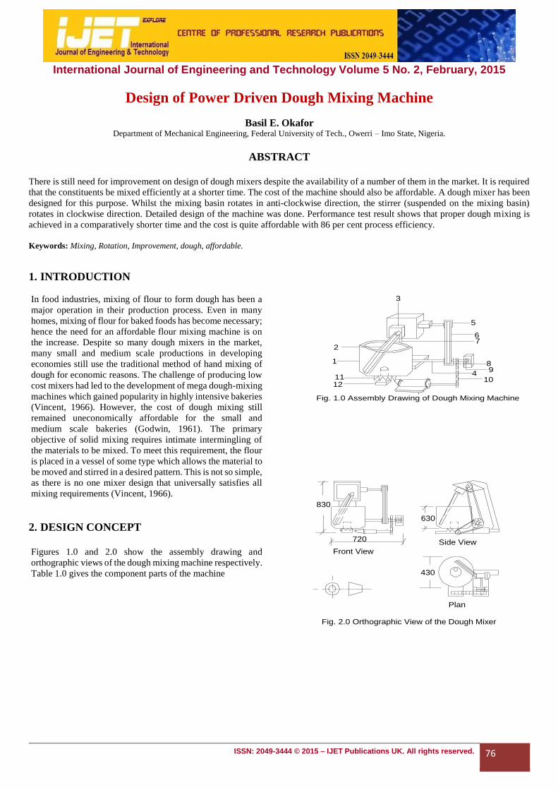
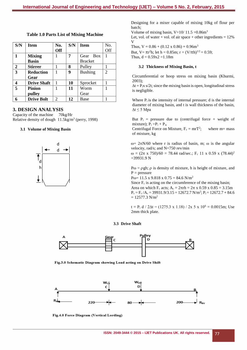
Figures 1.0 and 2.0 show the assembly drawing and
orthographic views of the dough mixing machine respectively.
Table 1.0 gives the component parts of the machine
Fig. 1.0 Assembly Drawing of Dough Mixing Machine
3
5
6
2
1112
89
410
7
1
830
720
630
Front View
Side View
430
Plan
Fig. 2.0 Orthographic View of the Dough Mixer
International Journal of Engineering and Technology (IJET) – Volume 5 No. 2, February, 2015
ISSN: 2049-3444 © 2015 – IJET Publications UK. All rights reserved. 77
Table 1.0 Parts List of Mixing Machine
S/N Item No.
Off
S/N Item No.
Off
1 Mixing
Basin
1 7 Gear Box
Bracket
1
2 Stirrer 1 8 Pulley 1
3 Reduction
Gear
1 9 Bushing 2
4 Drive Shaft 1 10 Sprocket 1
5 Pinion
pulley
1 11 Worm
Gear
1
6 Drive Bolt 2 12 Base 1
3. DESIGN ANALYSIS Capacity of the machine 70kg/Hr
Relative density of dough 11.5kg/m3 (perry, 1998)
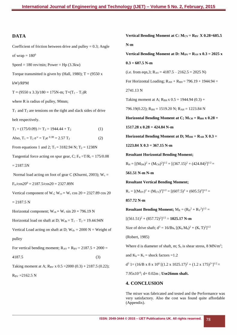
3.1 Volume of Mixing Basin
Designing for a mixer capable of mixing 10kg of flour per
batch;
Volume of mixing basin, V=10/ 11.5 =0.86m3
Let, vol. of water + vol. of air space + other ingredients = 12%
V
Thus, V = 0.86 + (0.12 x 0.86) = 0.96m3
But, V= r2h; let h = 0.85m; r = (V/h)1/2 = 0.59;
Thus, d = 0.59x2 =1.18m
3.2 Thickness of Mixing Basin, t
Circumferential or hoop stress on mixing basin (Khurmi,
2003);
∆t = Pix s/2t; since the mixing basin is open, longitudinal stress
is negligible.
Where Pi is the intensity of internal pressure; d is the internal
diameter of mixing basin, and t is wall thickness of the basin,
∆t ≤ 5 Mpa
But Pi = pressure due to (centrifugal force + weight of
mixture); Pi =Pi + Pw
Centrifugal Force on Mixture, Fc = mrT2; where m= mass
of mixture, kg
= 2N/60 where r is radius of basin, m; ω is the angular
velocity, rad/s; and N=750 rev/min
= (2 x 750)/60 = 78.44 rad/sec.; Fc 11 x 0.59 x (78.44)2
=39931.9 N
P = gh; is density of mixture, h is height of mixture, and
P = pressure
P= 11.5 x 9.818 x 0.75 = 84.6 N/m2
Since Fc is acting on the circumference of the mixing basin;
Area on which Fc acts; Ac = 2rh = 2 x 0.59 x 0.85 = 3.15m
Pc = Fc /Ac = 39931.9/3.15 = 12672.7 N/m2; Pi = 12672.7 + 84.6
= 12577.3 N/m2
t = Pi d / 2∆t = (1275.3 x 1.18) / 2x 5 x 106 = 0.0015m; Use
2mm thick plate.
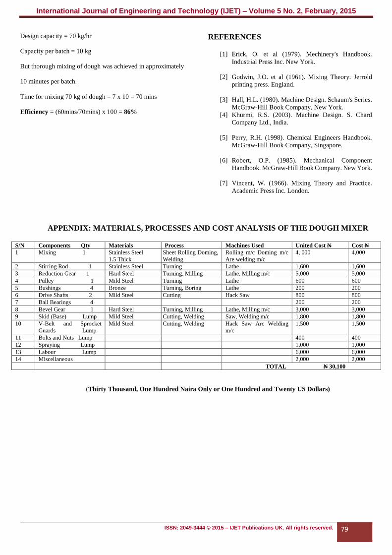
3.3 Drive Shaft
d
d
d
h
International Journal of Engineering and Technology (IJET) – Volume 5 No. 2, February, 2015
ISSN: 2049-3444 © 2015 – IJET Publications UK. All rights reserved. 78
DATA
Coefficient of friction between drive and pulley = 0.3; Angle
of wrap = 1800
Speed = 180 rev/min; Power = Hp (3.3kw)
Torque transmitted is given by (Hall, 1980); T = (9550 x
kW)/RPM
T = (9550 x 3.3)/180 = 175N-m; T=(T1 – T2)R
where R is radius of pulley, 90mm;
T1 and T2 are tensions on the tight and slack sides of drive
belt respectively.
T1 = (175/0.09) /= T2 = 1944.44 + T2 (1)
Also, T1 = T2 e:v = T2e 0.3B = 2.57 T2 (2)
From equations 1 and 2; T1 = 3182.94 N; T2 = 1238N
Tangential force acting on spur gear, C; Ftc =T/Rc = 175/0.08
= 2187.5N
Normal load acting on foot of gear C (Khurmi, 2003); Wc =
Ftc/cos200 = 2187.5/cos20 = 2327.89N
Vertical component of Wc; Wcv = Wc cos 20 = 2327.89 cos 20
= 2187.5 N
Horizontal component; Wch = Wc sin 20 = 796.19 N
Horizontal load on shaft at D; Wdh = T1 – T2 = 19.44.94N
Vertical Load acting on shaft at D; Wdv = 2000 N = Weight of
pulley
For vertical bending moment; RAV + RBV = 2187.5 + 2000 =
4187.5 (3)
Taking moment at A; RBV x 0.5 =2000 (0.3) + 2187.5 (0.22);
RBV =2162.5 N
Vertical Bending Moment at C: MCV = RBV X 0.28=605.5
N-m
Vertical Bending Moment at D: MDV = RAV x 0.3 = 2025 x
0.3 = 607.5 N-m
(i.e. from eqn,3; RAV = 4187.5 – 2162.5 = 2025 N)
For Horizontal Loading; RAH + RBH = 796.19 + 1944.94 =
2741.13 N
Taking moment at A; RBH x 0.5 = 1944.94 (0.3) +
796.19(0.22); RBH = 1519.20 N; RAH = 1223.84 N
Horizontal Bending Moment at C; MCH = RBH x 0.28 =
1517.28 x 0.28 = 424.84 N-m
Horizontal Bending Moment at D; MDH = RAH X 0.3 =
1223.84 X 0.3 = 367.15 N-m
Resultant Horizontal Bending Moment;
RH = [(MDH)2 + (MCH)2]1/2 = [(367.15)2 + (424.84)2]1/2 =
561.51 N-m N-m
Resultant Vertical Bending Moment;
Rv = [(MDV)2 + (MCV)2]1/2 = [(607.5)2 + (605.5)2]1/2 =
857.72 N-m
Resultant Bending Moment; MR = (RH2 + RV
2)1/2 =
[(561.51)2 + (857.72)2]1/2 = 1025.17 N-m
Size of drive shaft; d3 = 16/Bss [(Kb Mb)2 + (Kt T)2]1/2
(Robert, 1985)
Where d is diameter of shaft, m; Ss is shear stress, 8 MN/m2;
and Kb = Kt = shock factors =1.2
d3 1= (16/B x 8 x 10⁶ [(1.2 x 1025.17)2 + (1.2 x 175)2+]1/2 =
7.95x10⁻⁶; d= 0.02m ; Use26mm shaft.
4. CONCLUSION
The mixer was fabricated and tested and the Performance was
very satisfactory. Also the cost was found quite affordable
(Appendix).
International Journal of Engineering and Technology (IJET) – Volume 5 No. 2, February, 2015
ISSN: 2049-3444 © 2015 – IJET Publications UK. All rights reserved. 79
Design capacity = 70 kg/hr
Capacity per batch = 10 kg
But thorough mixing of dough was achieved in approximately
10 minutes per batch.
Time for mixing 70 kg of dough = 7 x 10 = 70 mins
Efficiency = (60mins/70mins) x 100 = 86%
REFERENCES
[1] Erick, O. et al (1979). Mechinery's Handbook.
Industrial Press Inc. New York.
[2] Godwin, J.O. et al (1961). Mixing Theory. Jerrold
printing press. England.
[3] Hall, H.L. (1980). Machine Design. Schaum's Series.
McGraw-Hill Book Company, New York.
[4] Khurmi, R.S. (2003). Machine Design. S. Chard
Company Ltd., India.
[5] Perry, R.H. (1998). Chemical Engineers Handbook.
McGraw-Hill Book Company, Singapore.
[6] Robert, O.P. (1985). Mechanical Component
Handbook. McGraw-Hill Book Company. New York.
[7] Vincent, W. (1966). Mixing Theory and Practice.
Academic Press Inc. London.
APPENDIX: MATERIALS, PROCESSES AND COST ANALYSIS OF THE DOUGH MIXER
S/N Components Qty Materials Process Machines Used United Cost N Cost N
1 Mixing 1 Stainless Steel
1.5 Thick
Sheet Rolling Doming,
Welding
Rolling m/c Doming m/c
Are welding m/c
4, 000 4,000
2 Stirring Rod 1 Stainless Steel Turning Lathe 1,600 1,600
3 Reduction Gear 1 Hard Steel Turning, Milling Lathe, Milling m/c 5,000 5,000
4 Pulley 1 Mild Steel Turning Lathe 600 600
5 Bushings 4 Bronze Turning, Boring Lathe 200 200
6 Drive Shafts 2 Mild Steel Cutting Hack Saw 800 800
7 Ball Bearings 4 200 200
8 Bevel Gear 1 Hard Steel Turning, Milling Lathe, Milling m/c 3,000 3,000
9 Skid (Base) Lump Mild Steel Cutting, Welding Saw, Welding m/c 1,800 1,800
10 V-Belt and Sprocket
Guards Lump
Mild Steel Cutting, Welding Hack Saw Arc Welding
m/c
1,500 1,500
11 Bolts and Nuts Lump 400 400
12 Spraying Lump 1,000 1,000
13 Labour Lump 6,000 6,000
14 Miscellaneous 2,000 2,000
TOTAL N 30,100
(Thirty Thousand, One Hundred Naira Only or One Hundred and Twenty US Dollars)