joint permit application - som - state of michigan · web viewcomplete this form for each bridge /...
TRANSCRIPT
U.S. Army Corps of Engineers Detroit District Office Phone: 313-226-2218, Fax: 313-226-6763 Website: www.lre.usace.army.mil
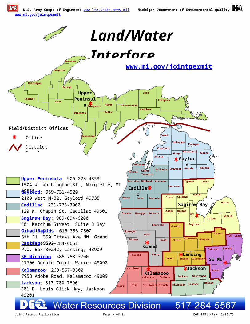
Michigan Department of Environmental Quality Water Resources Division See staff map on page iii for contact informationWebsite: www.mi.gov/jointpermit
Joint Permit ApplicationFor Work in Inland Lakes and Streams, Great Lakes, Wetlands, Floodplains, Dams,
High Risk Erosion Areas and Critical Dune Areaswww.mi.gov/jointpermit
What is the purpose of the Joint Permit Application?
This Joint Permit Application was developed to facilitate the state and federal permit application process administered by the Michigan Department of Environmental Quality (DEQ) and the U.S. Army Corps of Engineers (USACE).
The Joint Permit Application is a multi-purpose application used to describe and quantify proposed activities regulated by the DEQ and/or the USACE. This application is for those activities regulated by the following Parts of the Natural Resources and Environmental Protection Act, 1994 PA 451, as amended by the State of Michigan.
Part 301, Inland Lakes and Streams Part 325, Great Lakes Submerged Lands Part 303, Wetlands Protection Floodplain Regulatory Authority found in Part 31, Water Resources Protection Part 315, Dam Safety Part 323, Shorelands Protection and Management (High Risk Erosion Areas) Part 353, Sand Dunes Protection and Management (Critical Dune Areas)
The regulated activities are summarized in Appendix D. The statutes and rules are available at www.mi.gov/jointpermit.
This application is also for those activities regulated by the USACE within the waters of the United States under Section 10, Rivers and Harbors Act of 1899 (33 U.S.C. 403) and Section 404, Clean Water Act of 1977 (33 U.S.C. 1344).
Preapplication Meeting: This is an optional service available for activities proposed in inland lakes and streams (Part 301), wetlands (Part 303), and critical dune areas (Part 353). A preapplication meeting can answer many questions regarding whether or not a permit is required and the review process. The application form and fee schedule are available at www.mi.gov/jointpermit.
How do I complete the Joint Permit Application?
An accurate and complete application package is required for processing; inaccurate or missing information will delay processing.
There are three parts to a complete Joint Permit Application package:
1. Application Form2. Maps and Drawings3. Fee
Follow the checklists on the following page for each part of the application package.
When you have questions or need assistance in completing the application package refer to the following information on our website www.mi.gov/jointpermit or you may contact the appropriate district office, page iii, or through the website link “Who to Contact.”
Joint Permit Application Training Manual EZ Guides for small projects Acronyms in Appendix A Sample drawings in Appendix B Minor Project and General Permit Categories in Appendix C Fee schedule in Appendix C State and Federal Authority and Penalties in Appendix D Glossary in Appendix E
Joint Permit Application Page i of iv EQP 2731 (Rev. 2/2017)

U.S. Army Corps of Engineers www.lre.usace.army.mil Michigan Department of Environmental Quality www.mi.gov/jointpermit
Application ChecklistThe following website will provide township, range, section, latitude and longitude information:
www.mcgi.state.mi.us/wetlands/
In each section check all boxes that apply to your project.
Show and label property lines on the site plan.
Label existing and proposed contours, dimensions, excavation and/or fill on the site plans and cross sections.
Provide tables for multiple impact areas.
1. Application Form Complete Sections 1 through 9 of the application form. An authorization letter from the property owner if someone other than the property owner is
signing the application. Complete those Sections 10 through 20 that apply to your project. Follow the instructions at
the beginning of each section. For additional information, the instructions for each sample drawing in Appendix B indicate the application sections you will most likely need to complete. Complete the application form as much as possible before adding attachments. Label each attachment with the applicant's name.
Stake or flag the area for site inspection including the property corners, proposed road or driveway centerlines, and areas of proposed impacts. The site must be flagged when the application is submitted.
2. Maps and Drawings All maps and drawings must be black and white, legible, reproducible, and sized to 8.5” x
11”. Aerial photographs do not substitute for site plans. If larger drawings or blueprints are required to show adequate detail for review, you may also submit one full size copy.
Vicinity Map: A map to the proposed project location that includes ALL streets, roads, intersections, highways, or cross-roads to the project. Do not assume review staff knows your project location.
Project Site Plan: Overhead drawings to scale or with dimensions, length and width, of the proposed project are required. Show and label property lines on the site plan.
Cross-section drawings are required. Provide the cross-sections and profile views to scale or with dimensions, length, width, and height.
Elevation data must include a description of the reference point or benchmark used and its corresponding elevation. For projects on the Great Lakes or Section 10 Waters, elevations must be provided in IGLD 85. For observed Great Lake water elevations in IGLD, visit the USACE website under “water levels”. If elevations are from still water, provide the observation date and water elevation. On inland sites, elevations can use NGVD 29, NAVD 88, a local datum or an assumed bench mark.
Provide descriptive photographs of the proposed work site showing vegetation if wetlands are involved or the shoreline for shore protection projects. All photographs must be labeled with your name and the date of the photograph, indicate what they show, and be referenced to the site plan. Proposed activities or structure(s) may be indicated directly on the photographs using indelible markers or ink pens. Provide aerial photographs 1:400 or larger for major projects.
3. Fee
Payment to the State of Michigan. Fees typically range from $50 to $4,000 depending on the type of project. Refer to Appendix C of the application and/or visit www.mi.gov/jointpermit to determine the appropriate fee for your project and for directions to pay by credit card or electronic fund transfer payment.
Applications should be sent directly to the district offices. Please refer to page iii, or refer to www.mi.gov/jointpermit “who to contact” for address and/or phone number. Applications that cross county boundaries should be sent to the district containing the primary work effort.
Applications for dams regulated under Part 315 or from public agencies eligible to receive federal and/or state transportation funding for a project involving public roadways, non-motorized paths, airports, or related facilities should be mailed to: DEQ, WRD, P.O. BOX 30458, LANSING, MI 48909-7958.
Joint Permit Application Page ii of iv EQP 2731 (Rev. 2/2017)
U.S. Army Corps of Engineers www.lre.usace.army.mil Michigan Department of Environmental Quality www.mi.gov/jointpermit
Joint Permit Application Page iii of iv EQP 2731 (Rev. 2/2017)
Jackson
Land/Water InterfacePermitting Staff Map
Berrien Cass St. Joseph Branch
Van Buren
KalamazooKalamazoo Calhoun Jackson Washtenaw
Wayne
Hillsdale Lenawee Monroe
SE MILansing
Grand Rapids
Saginaw Bay
Cadillac
Gaylord
Upper Peninsula
Oakland Macomb
St. ClairLapeer
Genesee
LivingstonInghamEatonBarryAllegan
Ottawa
Kent
Ionia ClintonShiawassee
Muskegon
Montcalm GratiotSaginaw
TuscolaSanilac
Huron
Oceana Newaygo MecostaIsabella Midland
Bay
Mason Lake Osceola Clare GladwinArenac
Manistee Wexford Missaukee
Roscommon
Ogemaw Iosco
Benzie Grand Traverse
Kalkaska Crawford Oscoda AlconaLeelanau
AntrimOtsego
Montmorency Alpena
Presque IsleCheboygan
Charlevoix
Emmet
Chippewa
Luce
MackinacSchoolcraftAlger
Delta
Marquette
Menominee
Dickinson
Baraga
IronGogebic
Ontonagon
Houghton
Keweenaw
Office Location
Field/District Offices
Upper Peninsula: 906-228-48531504 W. Washington St., Marquette, MI 49855
Gaylord: 989-731-4920 2100 West M-32, Gaylord 49735
Cadillac: 231-775-3960120 W. Chapin St, Cadillac 49601
Saginaw Bay: 989-894-6200401 Ketchum Street, Suite B Bay City 48708
Grand Rapids: 616-356-05005th Fl. 350 Ottawa Ave NW, Grand Rapids 49503
Lansing: 517-284-6651P.O. Box 30242, Lansing, 48909
SE Michigan: 586-753-370027700 Donald Court, Warren 48092
Kalamazoo: 269-567-35007953 Adobe Road, Kalamazoo 49009
Jackson: 517-780-7690301 E. Louis Glick Hwy, Jackson 49201
www.mi.gov/jointpermit
District Boundary

U.S. Army Corps of Engineers www.lre.usace.army.mil Michigan Department of Environmental Quality www.mi.gov/jointpermit
APPENDICES
Appendix A: Acronyms and Abbreviations...........................................................................................................................A-1Appendix B: Sample Drawings
1. General Instructions for all Drawings and Sample Site Location Maps.....................................................B-12. Inland Lake Shore Protection....................................................................................................................B-23. Bulkhead/Seawall......................................................................................................................................B-24. Pond Construction.....................................................................................................................................B-35. Floodplain Fill............................................................................................................................................B-36. Wetland Boardwalk...................................................................................................................................B-47. Dredging...................................................................................................................................................B-48. Driveway Across Wetland.........................................................................................................................B-59. Residential Wetland Fill and Boardwalk Construction...............................................................................B-510. Docks - Piers - Mooring Piles....................................................................................................................B-611. Beach Sanding..........................................................................................................................................B-612. Pipe/Utility Crossings in a Trench.............................................................................................................B-713. Pipe/Utility Crossings using Directional Bore............................................................................................B-714. Bridge or Culvert (4 drawings)..................................................................................................................B-815. Dam Construction...................................................................................................................................B-1216. Water Intake............................................................................................................................................B-1217. Great Lakes Shore Protection.................................................................................................................B-1318. Maintenance Dredge Channel................................................................................................................B-1319. Proposed Residence in a High Risk Erosion Area..................................................................................B-1420. Proposed Residence in a Critical Dune Area..........................................................................................B-1421. Marina Site Plan......................................................................................................................................B-1522. Outlet Pipe..............................................................................................................................................B-1623. Temporary Logging Road Crossing........................................................................................................B-16
Appendix C: Fees and Categories for Minor Project and General Permit for Minor Activities..............................................C-1Appendix D: State Authority, Federal Authority, Privacy Act Statement, and State and Federal Penalties.........................D-1Appendix E: Glossary (listed words are italicized in the application package).....................................................................E-1
Application status can be viewed on the Water Resources Division (WRD) website at www.michigan.gov/miwaters. During the application period, if any information is missing from the application or if any clarification is needed regarding materials provided, the application is incomplete and staff will request the information from the applicant/agent by letter, email, fax or phone call. If a complete response is not provided within 30 days, the application will be closed. Some regulatory parts allow extensions if requested within the 30 day time frame. Once the WRD has received the information necessary for review of the project, including a thoroughly completed application, consistent drawings that have adequate detail for review and the full application fee, the file will be reviewed for final processing. A mailed postcard or a public notice will provide the file number and the telephone number of the office where the application is being processed. The review time to determine if an application is complete for processing ranges from 15 to 30 days. Technical processing times, after the application is administratively complete, may range from 60 to 90 days. Processing times will be longer if a public hearing is held. Staff from your local District/Field Office may visit the project site and may request additional information prior to a decision on the application. Application fees are not refundable or transferable.
If a federal permit will also be required, a copy of the permit application will be sent to the Detroit District Office, USACE, for processing at the federal level. Additional copies of this application form can be downloaded from the WRD website at www.mi.gov/jointpermit or can be photocopied from the original. If you have any questions about the permitting process or if you need to modify your application, you can contact the WRD by phone or fax at the addresses on the previous page, or email at [email protected].
Joint Permit Application Page iv of iv EQP 2731 (Rev. 2/2017)
U.S. Army Corps of Engineers www.lre.usace.army.mil Michigan Department of Environmental Quality www.mi.gov/jointpermit
AG
ENC
Y U
SEPrevious USACE File Number
Dat
eR
ecei
ved DEQ File Number
USACE File Number Fee received $
Validate that all parts of this checklist are submitted with the application package. Fill out application and additional pages as needed. All items in Sections 1 through 9 are completed. Project-specific Sections 10 through 20 are completed. Dimensions, volumes, and calculations are provided for all impact areas. All information contained in the headings for the appropriate Sections (1-20) are addressed, and identified attachments () are included. Map, site plan(s), cross sections; one set must be black and white on 8 ½ by 11 inch paper; photographs. Application fee is attached.
1 Project Location Information For Latitude, Longitude, and TRS info anywhere in Michigan see www.mcgi.state.mi.us/wetlands/
Project Address (road, if no street address)
Zip Code
Municipality (Township/Village/City)
County
Property Tax Identification Number(s)
Latitude . N
Township/Range/Section (TRS)
T N or S; R E or W; Sec OR Private Claim #
Subdivision/Plat and Lot Number
Longitude - W
2 Applicant and Agent Information
Owner/Applicant (individual or corporate name)
Agent/Contractor (firm name and contact person)
Mailing Address Mailing Address
City State Zip Code City State Zip Code
Contact Phone Number
Fax
Contact Phone Number
Fax
Email E-mail No Yes Is the applicant the sole owner of all property on which this project is to be constructed and all property involved or impacted by
this project? If no, attach letter(s) of authorization from all property owners including the owner of the disposal site.Property Owner’s Name (If different from applicant) Mailing Address
Contact Phone Number City State Zip Code 3 Project Description
Project Name Preapplication File Number – – –P
Name of Water body Date project staked/flagged
The proposed project is on, within, or involves (check all that apply) Project Use an inland lake (5 acres or more) a pond (less than 5 acres) a stream, river, ditch or drain a legally established County Drain
Date Drain was established a channel/canal 500 feet of an existing water body
a Great Lake or Section 10 Waters a wetland a 100-year floodplain a dam a designated high risk erosion area a designated critical dune area a designated environmental area
private commercial public/government project is receiving federal/state
transportation funds Wetland Restoration other
Indicate the type of permit being applied for: General Permit Minor Project Individual (All other projects.) See Appendix C.
Written Summary of All Proposed Activities
Construction Sequence and Methods
Joint Permit Application Page 1 of 14 EQP 2731 (Rev. 2/2017)
U.S. Army Corps of Engineers www.lre.usace.army.mil Michigan Department of Environmental Quality www.mi.gov/jointpermit
4 Project Purpose, Use and Alternatives Attach additional sheets as necessary.
Describe the purpose of the project and its intended use; include any new development or expansion of an existing land use.
Describe the alternatives considered to avoid or minimize resource impacts. Include factors such as, but to limited to, alternative locations, project layout and design, and construction technologies. For utility crossings include alternative routes and construction methods.
5 Locating Your Project Site Attach a legible black and white map with a North arrow.
Names of roads of closest intersection
Directions from main intersection to the project site, with distances from the best and nearest visible landmark and water body
Description of buildings on the site (color; 1 or 2 story, other)
Description of adjacent landmarks or buildings (address; color; etc)
How can your site be identified if there is no visible address?
6 Easements and Other Permits
No Yes Is there a conservation easement or other easement, deed restriction, lease, or other encumbrance upon the property? If yes, attach a copy. Provide copies of court orders and legal lake levels if applicable.
List all other federal, interstate, state, or local agency authorizations including required assurances for Critical Dune Area projects.Agency Type of Approval Number Date Applied Date approved /denied Reason for denial
7 Compliance
If a permit is issued, when will the activity begin? (M/D/Y) Proposed completion date (M/D/Y)
No Yes Has any construction activity commenced or been completed in a regulated area? If Yes, identify the portion(s) underway or completed on drawings or attach project specifications and give completion date(s).
No Yes Were the regulated activities conducted under a DEQ and/or USACE permit? If Yes, list the permit numbers
No Yes Are you aware of any unresolved violations of environmental law or litigation involving the property? If Yes, attach explanation.
8 Adjoining Property Owners Provide current mailing addresses. Attach additional sheets/labels for long lists.
Established Lake Board Lake Association
Contact Person
Mailing Address
City
State and Zip Code
List all adjoining property owners. If you own the adjoining lot, provide the requested information for the first adjoining parcel that is not owned by you. Property Owner’s Name Mailing Address City State and Zip Code
Joint Permit Application Page 2 of 14 EQP 2731 (Rev. 2/2017)

U.S. Army Corps of Engineers www.lre.usace.army.mil Michigan Department of Environmental Quality www.mi.gov/jointpermit
9 Applicant’s Certification Read carefully before signing.
I am applying for a permit(s) to authorize the activities described herein. I certify that I am familiar with the information contained in this application; that it is true and accurate; and, to the best of my knowledge, that it is in compliance with the State Coastal Zone Management Program. I understand that there are penalties for submitting false information and that any permit issued pursuant to this application may be revoked if information on this application is untrue. I certify that I have the authority to undertake the activities proposed in this application. By signing this application, I agree to allow representatives of the DEQ, USACE, and/or their agents or contractors to enter upon said property in order to inspect the proposed activity site before and during construction and after the completion of the project. I understand that I must obtain all other necessary local, county, state, or federal permits and that the granting of other permits by local, county, state, or federal agencies does not release me from the requirements of obtaining the permit requested herein before commencing the activity. I understand that the payment of the application fee does not guarantee the issuance of a permit.
Property Owner Agent/Contractor Corp. or Public Agency / Title
Printed Name
Signature Date
Joint Permit Application Page 3 of 14 EQP 2731 (Rev. 2/2017)
U.S. Army Corps of Engineers www.lre.usace.army.mil Michigan Department of Environmental Quality www.mi.gov/jointpermit
10 Projects Impacting Inland Lakes, Streams, Great Lakes, Wetlands or Floodplains
Complete only those sections A through M applicable to your project. If your project impacts wetlands also complete Section 12. If your project impacts regulated floodplains also complete Section 13. To calculate volume in cubic yards (cu yd), multiply the average length in feet (ft) times the average width (ft) times the average depth (ft)
and divide by 27. Example: (25 ft long x 10 ft wide x 2 feet deep) / 27 = 18.5 cubic yards Some projects on the Great Lakes require an application for conveyance prior to Joint Permit Application completeness. Provide a black and white overall site plan, with cross-section and profile drawings. Show existing lakes, streams, wetlands, and other water features; existing structures; and the location of all proposed structures, land change activities and soil erosion and sedimentation control measures. Review Appendix B and EZ Guides for aid in providing complete site-specific drawings. Provide tables for multiple impact areas or multiple activities such as multiple fill areas or multiple culverts. Include your calculations.
Water Level ElevationOn inland waters NGVD 29 NAVD 88 other Observed water elevation (ft) date of observation (M/D/Y)
On a Great Lake IGLD 85 surveyed converted from observed still water elevation. A. PROJECTS REQUIRING FILL (See All Sample Drawings)
Attach a site plan and cross-section views to scale showing maximum and average fill dimensions with calculations. For multiple impact areas on a site provide a table with location, dimensions and volumes for each fill area.
Purpose bioengineered shore protection boat ramp boat well bridge or culvert crib dock
riprap seawall swim area other
Dimensions of fill (ft)Length Width Maximum Depth
Total volume (cubic yards)
Volume below OHWM (cubic yards)
Maximum water depth in fill area (ft) Area filled (sq ft) Will filter fabric be used under proposed fill?
No Yes (If Yes, type)
Fill will extend feet into the water from the shoreline and upland feet out of the water.
Type of clean fill peastone % sand % gravel % other
Source of clean fill commercial on-site If on-site, show location on site plan. other If other, attach description of location.
B. PROJECTS REQUIRING DREDGING OR EXCAVATION (See Sample Drawings) Refer to www.mi.gov/jointpermit for spoils disposal and authorization requirements.
Attach a site plan and cross-section views to scale showing maximum and average dredge or excavation dimensions with calculations. For multiple impact areas on a site provide a table with location, dimensions and volumes for each dredge/excavation area. Purpose boat ramp boat well bridge or culvert maintenance dredge
navigation pond/basin other
Dimensions (ft) Length Width Maximum Depth
Total volume (cu yds)
Volume below OHWM (cu yds)
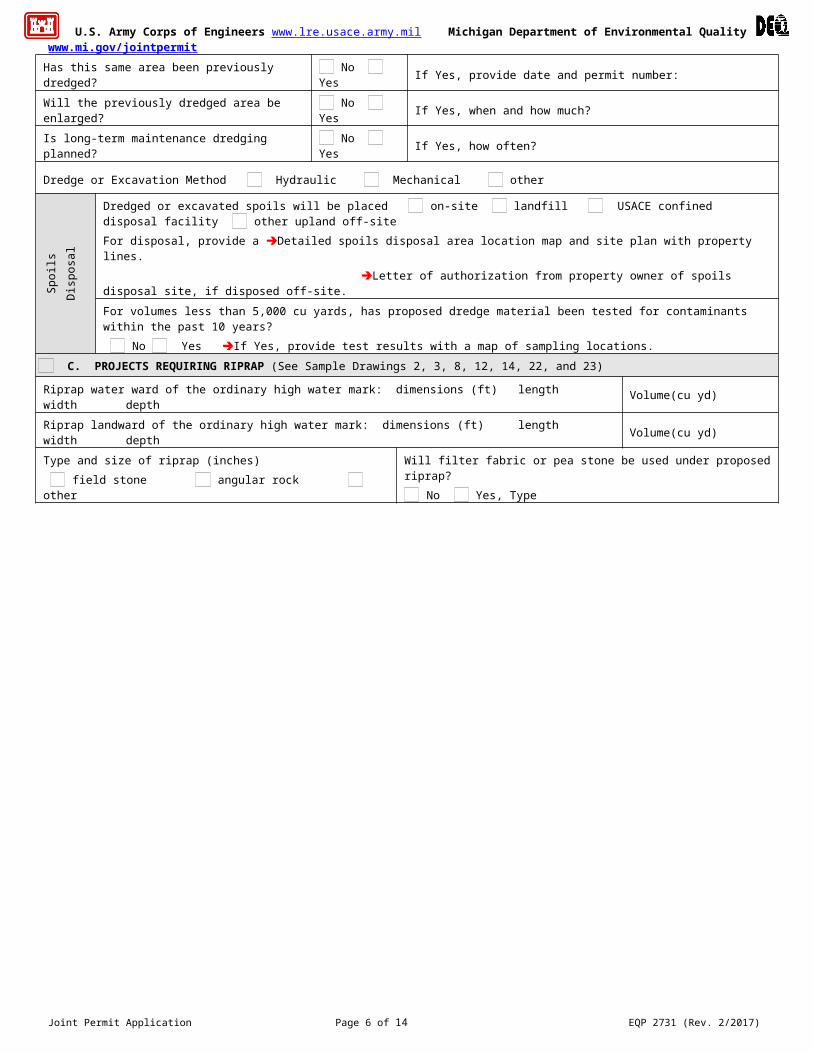
Has this same area been previously dredged? No Yes If Yes, provide date and permit number:
Will the previously dredged area be enlarged? No Yes If Yes, when and how much?
Is long-term maintenance dredging planned? No Yes If Yes, how often?
Dredge or Excavation Method Hydraulic Mechanical other
Spo
ilsD
ispo
sal
Dredged or excavated spoils will be placed on-site landfill USACE confined disposal facility other upland off-siteFor disposal, provide a Detailed spoils disposal area location map and site plan with property lines. Letter of authorization from property owner of spoils disposal site, if disposed off-site.
For volumes less than 5,000 cu yards, has proposed dredge material been tested for contaminants within the past 10 years? No Yes If Yes, provide test results with a map of sampling locations.
C. PROJECTS REQUIRING RIPRAP (See Sample Drawings 2, 3, 8, 12, 14, 22, and 23)
Riprap water ward of the ordinary high water mark: dimensions (ft) length width depth Volume(cu yd)
Riprap landward of the ordinary high water mark: dimensions (ft) length width depth Volume(cu yd)
Type and size of riprap (inches) field stone angular rock other
Will filter fabric or pea stone be used under proposed riprap? No Yes, Type
Joint Permit Application Page 4 of 14 EQP 2731 (Rev. 2/2017)

U.S. Army Corps of Engineers www.lre.usace.army.mil Michigan Department of Environmental Quality www.mi.gov/jointpermit
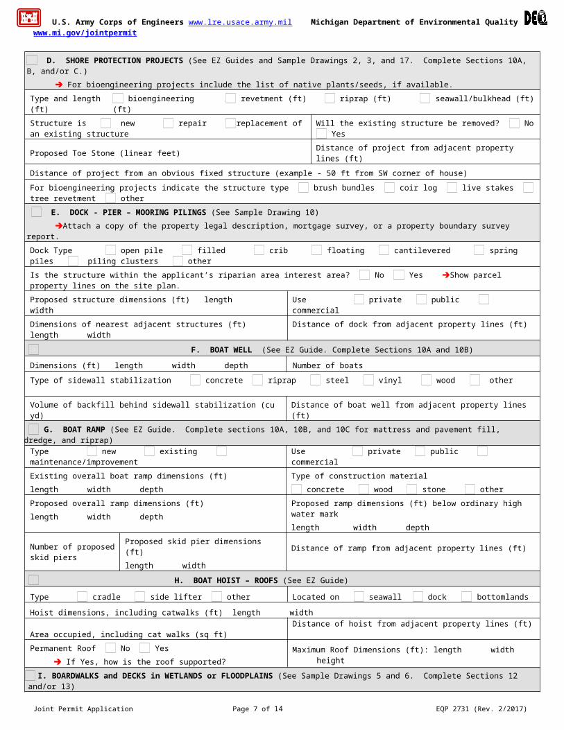
D. SHORE PROTECTION PROJECTS (See EZ Guides and Sample Drawings 2, 3, and 17. Complete Sections 10A, B, and/or C.) For bioengineering projects include the list of native plants/seeds, if available.
Type and length (ft) bioengineering (ft) revetment (ft) riprap (ft) seawall/bulkhead (ft)
Structure is new repair replacement of an existing structure Will the existing structure be removed? No Yes
Proposed Toe Stone (linear feet) Distance of project from adjacent property lines (ft)
Distance of project from an obvious fixed structure (example - 50 ft from SW corner of house)
For bioengineering projects indicate the structure type brush bundles coir log live stakes tree revetment other E. DOCK - PIER – MOORING PILINGS (See Sample Drawing 10)
Attach a copy of the property legal description, mortgage survey, or a property boundary survey report.
Dock Type open pile filled crib floating cantilevered spring piles piling clusters other
Is the structure within the applicant’s riparian area interest area? No Yes Show parcel property lines on the site plan.
Proposed structure dimensions (ft) length width Use private public commercial
Dimensions of nearest adjacent structures (ft) length width Distance of dock from adjacent property lines (ft)
F. BOAT WELL (See EZ Guide. Complete Sections 10A and 10B)
Dimensions (ft) length width depth Number of boats
Type of sidewall stabilization concrete riprap steel vinyl wood other
Volume of backfill behind sidewall stabilization (cu yd) Distance of boat well from adjacent property lines (ft)
G. BOAT RAMP (See EZ Guide. Complete sections 10A, 10B, and 10C for mattress and pavement fill, dredge, and riprap)
Type new existing maintenance/improvement Use private public commercial
Existing overall boat ramp dimensions (ft) length width depth
Type of construction material concrete wood stone other
Proposed overall ramp dimensions (ft)length width depth
Proposed ramp dimensions (ft) below ordinary high water mark length width depth
Number of proposed skid piers
Proposed skid pier dimensions (ft)length width
Distance of ramp from adjacent property lines (ft)
H. BOAT HOIST – ROOFS (See EZ Guide)
Type cradle side lifter other Located on seawall dock bottomlands
Hoist dimensions, including catwalks (ft) length width
Area occupied, including cat walks (sq ft) Distance of hoist from adjacent property lines (ft)
Permanent Roof No Yes If Yes, how is the roof supported?
Maximum Roof Dimensions (ft): length width height
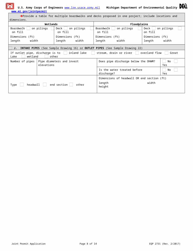
I. BOARDWALKS and DECKS in WETLANDS or FLOODPLAINS (See Sample Drawings 5 and 6. Complete Sections 12 and/or 13) Provide a table for multiple boardwalks and decks proposed in one project; include locations and dimensions.
Wetlands FloodplainsBoardwalk on pilings on fillDimensions (ft)length width
Deck on pilings on fillDimensions (ft)length width
Boardwalk on pilings on fillDimensions (ft)length width
Deck on pilings on fillDimensions (ft)length width
J. INTAKE PIPES (See Sample Drawing 16) or OUTLET PIPES (See Sample Drawing 22)
If outlet pipe, discharge is to inland lake stream, drain or river overland flow Great Lake wetland other
Number of pipes
Pipe diameters and invert elevations
Does pipe discharge below the OHWM? No YesIs the water treated before discharge? No Yes
Type headwall end section other Dimensions of headwall OR end section (ft)length width height
Joint Permit Application Page 5 of 14 EQP 2731 (Rev. 2/2017)
U.S. Army Corps of Engineers www.lre.usace.army.mil Michigan Department of Environmental Quality www.mi.gov/jointpermit
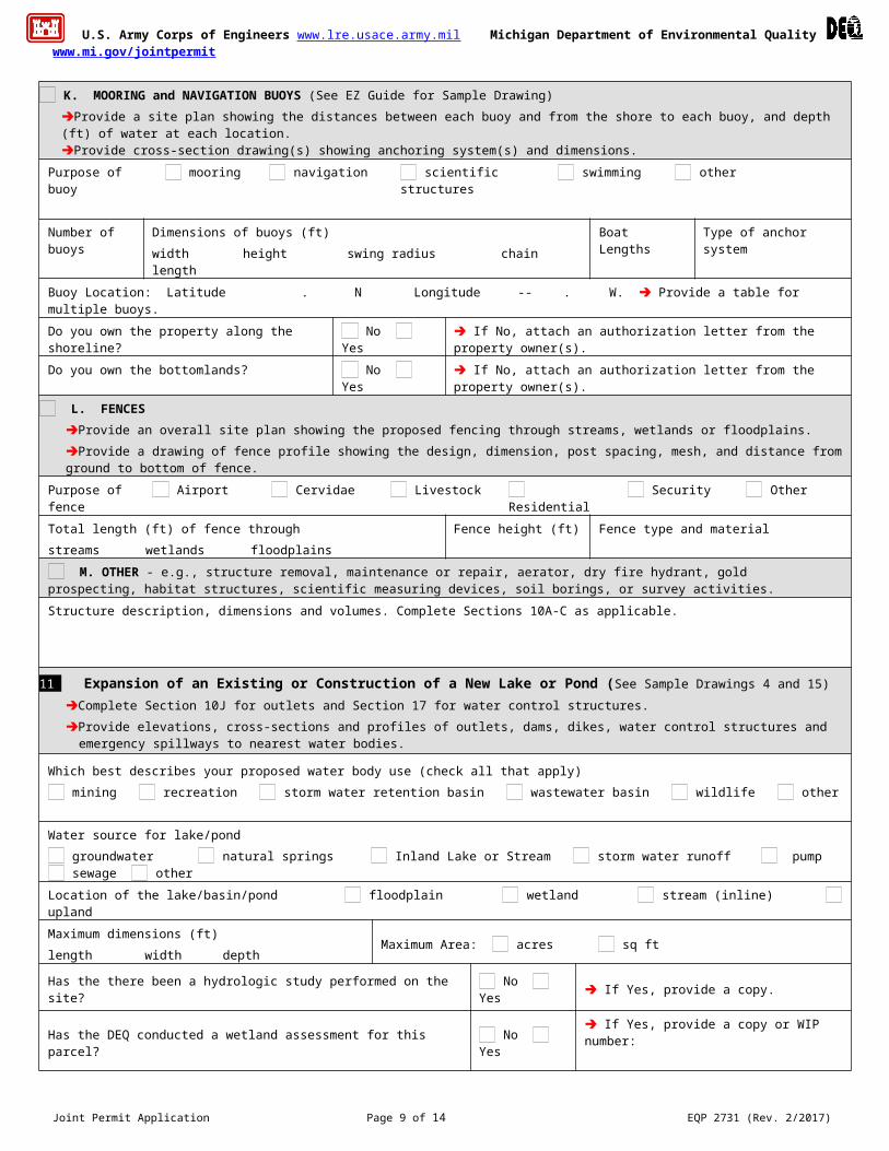
K. MOORING and NAVIGATION BUOYS (See EZ Guide for Sample Drawing)Provide a site plan showing the distances between each buoy and from the shore to each buoy, and depth (ft) of water at each location.Provide cross-section drawing(s) showing anchoring system(s) and dimensions.
Purpose of buoy mooring navigation scientific structures swimming other
Number of buoys
Dimensions of buoys (ft)width height swing radius chain length
Boat Lengths
Type of anchor system
Buoy Location: Latitude . N Longitude -- . W. Provide a table for multiple buoys.
Do you own the property along the shoreline? No Yes If No, attach an authorization letter from the property owner(s).
Do you own the bottomlands? No Yes If No, attach an authorization letter from the property owner(s).
L. FENCES Provide an overall site plan showing the proposed fencing through streams, wetlands or floodplains.Provide a drawing of fence profile showing the design, dimension, post spacing, mesh, and distance from ground to bottom of fence.
Purpose of fence
Airport Cervidae Livestock Residential Security Other
Total length (ft) of fence throughstreams wetlands floodplains
Fence height (ft)
Fence type and material
M. OTHER - e.g., structure removal, maintenance or repair, aerator, dry fire hydrant, gold prospecting, habitat structures, scientific measuring devices, soil borings, or survey activities. Structure description, dimensions and volumes. Complete Sections 10A-C as applicable.
11 Expansion of an Existing or Construction of a New Lake or Pond (See Sample Drawings 4 and 15)Complete Section 10J for outlets and Section 17 for water control structures.Provide elevations, cross-sections and profiles of outlets, dams, dikes, water control structures and emergency spillways to nearest water
bodies.
Which best describes your proposed water body use (check all that apply) mining recreation storm water retention basin wastewater basin wildlife other
Water source for lake/pond groundwater natural springs Inland Lake or Stream storm water runoff pump sewage other
Location of the lake/basin/pond floodplain wetland stream (inline) upland
Maximum dimensions (ft)length width depth
Maximum Area: acres sq ft
Has the there been a hydrologic study performed on the site? No Yes If Yes, provide a copy.
Has the DEQ conducted a wetland assessment for this parcel? No Yes If Yes, provide a copy or WIP number:
Has a professional wetland delineation been conducted for this parcel? No Yes
If Yes, provide a copy with data sheets.
Spo
ils
Dis
posa
l
Dredged or excavated spoils will be placed on-site landfill USACE confined disposal facility other upland off-site
For disposal, provide a Detailed spoils disposal area location map and site plan with property lines.
Letter of authorization from property owner of spoils disposal site, if disposed off-site.
Joint Permit Application Page 6 of 14 EQP 2731 (Rev. 2/2017)
U.S. Army Corps of Engineers www.lre.usace.army.mil Michigan Department of Environmental Quality www.mi.gov/jointpermit
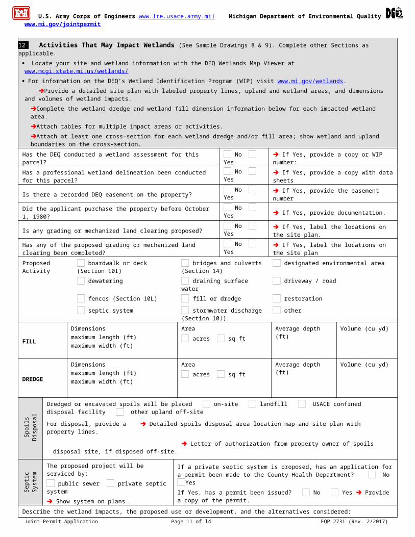
12 Activities That May Impact Wetlands (See Sample Drawings 8 & 9). Complete other Sections as applicable. Locate your site and wetland information with the DEQ Wetlands Map Viewer at www.mcgi.state.mi.us/wetlands/ For information on the DEQ’s Wetland Identification Program (WIP) visit www.mi.gov/wetlands. Provide a detailed site plan with labeled property lines, upland and wetland areas, and dimensions and volumes of wetland impacts.
Complete the wetland dredge and wetland fill dimension information below for each impacted wetland area. Attach tables for multiple impact areas or activities.Attach at least one cross-section for each wetland dredge and/or fill area; show wetland and upland boundaries on the cross-section.
Has the DEQ conducted a wetland assessment for this parcel? No Yes If Yes, provide a copy or WIP number:
Has a professional wetland delineation been conducted for this parcel? No Yes If Yes, provide a copy with data sheets
Is there a recorded DEQ easement on the property? No Yes If Yes, provide the easement number
Did the applicant purchase the property before October 1, 1980? No Yes If Yes, provide documentation.
Is any grading or mechanized land clearing proposed? No Yes If Yes, label the locations on the site plan.
Has any of the proposed grading or mechanized land clearing been completed?
No Yes If Yes, label the locations on the site plan
Proposed Activity boardwalk or deck (Section 10I) bridges and culverts (Section 14)
designated environmental area
dewatering draining surface water driveway / road
fences (Section 10L) fill or dredge restoration
septic system stormwater discharge (Section 10J)
other
FILL
Dimensionsmaximum length (ft) maximum width (ft)
Area acres sq ft
Average depth (ft)
Volume (cu yd)
DREDGE
Dimensionsmaximum length (ft) maximum width (ft)
Area acres sq ft
Average depth (ft)
Volume (cu yd)
Spo
ils
Dis
posa
l Dredged or excavated spoils will be placed on-site landfill USACE confined disposal facility other upland off-site
For disposal, provide a Detailed spoils disposal area location map and site plan with property lines.
Letter of authorization from property owner of spoils disposal site, if disposed off-site.
Sep
tic
Sys
tem The proposed project will be serviced by:
public sewer private septic system Show system on plans.
If a private septic system is proposed, has an application for a permit been made to the County Health Department? No YesIf Yes, has a permit been issued? No Yes Provide a copy of the permit.
Describe the wetland impacts, the proposed use or development, and the alternatives considered:
Does the project impact more than 1/3 acre of wetland? No Yes If Yes, submit a Mitigation Plan with the type and amount of mitigation proposed. For more information go to www.mi.gov/wetlands Describe how impacts to waters of the United States will be avoided and minimized:
Describe how the impact to waters of the United States will be compensated. OR Explain why compensatory mitigation should not be required for the proposed impacts.
Joint Permit Application Page 7 of 14 EQP 2731 (Rev. 2/2017)
U.S. Army Corps of Engineers www.lre.usace.army.mil Michigan Department of Environmental Quality www.mi.gov/jointpermit
13 Floodplain Activities (See Sample Drawing 5 and others. Complete other applicable sections.) For more information go to www.mi.gov/floodplainmanagement . This site also lists the projects and requirements for an expedited floodplain
review under “Expedited Review Information for Minor Floodplain Projects.” Examples of projects proposed within the non-floodway portions of the 100-year-floodplain which may qualify for an expedited review: Open
pile decks and boardwalks; residences, commercial/industrial facilities, garages and accessory structures; parking lots; pavilions, gazebos, large community playground structures; residential swimming pools
Examples of projects proposed within the floodway portions of the floodplain which may qualify for an expedited review: Open pile decks and boardwalks, (non-enclosed) that are anchored to prevent floatation and that do not extend over the bed and bank of a watercourse; parking lots constructed at grade or resurfacing that is no more than 4 inches above the existing grade; dry hydrants that do not require fill placement; scientific structure such as staff gauges, water monitoring devices, water quality testing devices, and core sampling devices which meet specific design criteria and fish structures that meet specific design criteria.
For expedited review include: Photographs of the work site labeled to identify what is being shown and with the direction of the photo clearly indicated. Include
photographs of any river or stream adjacent to the project. A letter or statement from the local unit of government acknowledging your proposed application. See the website for sample wording.
A hydraulic analysis or hydrologic analysis may be required to fully assess floodplain impacts. The state building code requires an Elevation Certificate for any building construction or addition in a floodplain. A sample form can be found at
www.fema.gov/nfip/elvinst.shtm. Attach additional sheets or tables for multiple proposed floodplain activities and provide hydraulic calculations. Show reference datum used on plans.
Proposed Activity fill excavation or cut 100-year floodplain elevation (ft) (if known)
Datum NGVD 29 NAVD 88 other other
Site is feet above ordinary high water mark (OHWM) OR observed water level. Date of observation (M/D/Y)
Fill volume below the 100-year floodplain elevation(cu yds)
Compensating cut volume below the 100-year floodplain elevation (cu yds)
Bui
ldin
gs a
nd/o
r Add
ition
s
Type of construction is residential garage/pole barn non residential other
Construction is new addition AND Serviced by public sewer private septic other
Lowest adjacent grade (ft): existing proposed
datum NGVD 29 NAVD 88 other
Existing Structure Information Proposed Structure Information
Foundation type basement Foundation type basement
concrete slab on grade pilings concrete slab on grade pilings
crawl space other crawl space other
Foundation floor elevation (ft) Foundation floor elevation (ft)
Height of crawl space/basement from finished foundation floor to bottom of floor joists (ft)
Height of crawl space/basement from finished foundation floor to bottom of floor joists (ft)
Elevation of 1st floor above basement floor/crawl space (ft) Elevation of 1st floor above basement floor/crawl space (ft)
For enclosed areas below the flood elevation, such as a crawl space, garages and accessory structures:
Area of proposed foundation (sq ft)
Elevation of proposed enclosed area (ft) datum NGVD 29 NAVD 88 other
Number of flood vents net opening of each vent (sq inches) lowest elevation of flood vents (ft)
Joint Permit Application Page 8 of 14 EQP 2731 (Rev. 2/2017)
U.S. Army Corps of Engineers www.lre.usace.army.mil Michigan Department of Environmental Quality www.mi.gov/jointpermit
14 Bridges and Culverts Including Foot and Cart Bridges. (See EZ Guides and Sample Drawings 5, 14A, 14B, 14C, 14D.) Complete other applicable Sections, including 10A-C. A hydraulic analysis or hydrologic analysis may be required to fully assess impacts. Attach hydraulic calculations. High Water Elevation - describe reference point and highest known water level above or below reference point and date of observation.
Attach additional sheets for multiple bridges and/or culverts.Provide detailed site-specific drawings of existing and proposed Plan and Elevation View at a scale adequate for detailed review.Provide all information in the boxes below; do not write in a reference to plan sheets. Show reference datum used on plans.
Stre
am In
form
atio
n
The site has a high water elevation (ft) above or below the Reference Point of Date observed
Reference datum used NGVD 29 NAVD 88 IGLD 85 (Great Lakes coastal areas) other
Average stream width (ft) at the ordinary high water mark (OHWM) outside the influence of any ponding or scour holes around the structure
Upstream
Downstream
Cross-sectional area of primary channel (sq ft) (See Sample Drawing 14C for more information) The width of the stream where the water begins to overflow its banks. Bankfull width (ft)
The invert of the stream 100-feet from structure (ft) Upstream
Downstream
Is the existing culvert perched? No Yes If Yes, provide a profile of the channel bottom at the high and low points for a distance of 200 feet upstream and downstream of the culvert.
Complete this form for each bridge / culvert location. Existing Proposed
Brid
ge
Number of bridge spans Bridge type (concrete box beam, concrete I-beam, timber, etc.) Bridge span ( length perpendicular to stream) (ft) Bridge width (parallel to stream) (ft) Bottom of bridge beam (ft) Upstream
Downstream Stream invert elevation at bridge (ft) Upstream
Downstream Bridge rise from bottom of beam to streambed (ft)
Cul
vert
Number of culverts Culvert type (arch, bottomless, box, circular, elliptical, etc.) Culvert material (concrete, corrugated metal, plastic, etc.) Culvert length (ft) Culvert width diameter (ft) Culvert height prior to any burying (ft) Depth culvert will be buried (ft) Elevation of culvert crown (ft) Upstream
Downstream Higher elevation of culvert invert OR streambed within culvert (ft) Upstream
Downstream
Com
plet
e fo
r bot
h B
ridge
s an
d C
ulve
rts
Entrance design (mitered, projecting, wingwalls, etc.) Total structure waterway opening above streambed (sq ft) Total structure waterway area below the 100-year elevation (sq ft) (if known) Elevation of road grade at structure (ft) Elevation of low point in road (ft) Distance from low point of road to mid-point of bridge crossing (ft) Length of approach fill from edge of bridge/culvert to existing grade (ft) A Licensed Professional Engineer may certify that your project will not cause a harmful interference for a range of flood discharges up to and including the 100-year flood discharge. The "Required Certification Language” is found under “forms” on the “maps, forms and documents” link from the www.mi.gov/jointpermit page or a copy may be requested by phone, email, or mail. A hydraulic report supporting this certification may also be required. Is Certification Language attached? No Yes
Joint Permit Application Page 9 of 14 EQP 2731 (Rev. 2/2017)
U.S. Army Corps of Engineers www.lre.usace.army.mil Michigan Department of Environmental Quality www.mi.gov/jointpermit
15 Stream, River, or Drain Construction , Relocation and Enclosure Activities Complete Section 10C for riprap activities. If side casting or other proposed activities will impact wetlands or floodplains, complete Sections 12 and 13, respectively.
Provide a scaled overall site plan showing existing lakes, streams, wetlands, and other water features; existing structures; and the location of all proposed structures and land change activities. Provide scaled cross-section (elevation) drawings necessary to clearly show existing and proposed conditions. For activities on legally established county drains, provide original design and proposed dimensions and elevations.
Stre
am
Info
rmat
ion Water elevation (ft) datum NGVD 29 NAVD 88 IGLD 85 (Great Lakes coastal areas) other
Show elevation on plans with description.
Dimensions (ft) of existing stream/drain channel (ft) length width depth
Existing channel average water depth in a normal year (ft)
Proposed Activity enclosure improvement maintenance new drain relocation wetlands other
If an enclosed structure is proposed, check material type concrete corrugated metal plastic other
Dimensions (ft) of the structure: diameter length Volume of fill (cu yds)
Will old/enclosed stream channel be backfilled to top of bank grade? No Yes
Length of channel to be abandoned (ft) Volume of fill (cu yds)
Dimensions (ft) of improved, maintained, new, relocated or wetland stream/drain channel.length width depth
Volume of dredge/excavation (cu yds)
How will slopes and bottom be stabilized? Proposed side slopes (vertical / horizontal)
Spo
ils
Dis
posa
l
Dredged or excavated spoils will be placed on-site landfill USACE confined disposal facility other upland off-site For disposal, provide a Detailed spoils disposal area location map and site plan with property lines. Letter of authorization from property owner of spoils disposal site, if disposed off-site.
16 Drawdown of an Impoundment If wetlands will be impacted, complete Section 12.
Type of drawdown over winter temporary one-time event annual event permanent (dam removal) other
Reason for drawdown Has there been a previous drawdown? No Yes If Yes, provide date (M/D/Y)
Previous DEQ permit number, if known
Does waterbody have established legal lake level? No Yes Not Sure Dam ID Number, if known
Extent of vertical drawdown (ft) Impoundment design head (ft) Number of adjoining or impacted property owners
Date drawdown would start (M/D/Y) Date drawdown would stop (M/D/Y) Rate of drawdown ( ft/day)
Date refilling would start (M/D/Y) Date refill would end (M/D/Y) Rate of refill (ft/day)
Type of outlet discharge structure to be used surface bottom mid-depth
Impoundment area at normal water level (acres)
Sediment depth behind impoundment discharge structure (ft)
Joint Permit Application Page 10 of 14 EQP 2731 (Rev. 2/2017)
U.S. Army Corps of Engineers www.lre.usace.army.mil Michigan Department of Environmental Quality www.mi.gov/jointpermit
17 Dam, Embankment, Dike, Spillway, or Control Structure Activities (See Sample Drawing 15)
For more information go to www.mi.gov/damsafety. If wetlands will be impacted, complete Section 12. Information on removing a dam is available at www.mi.gov/damsafety and following the Related Link –Dam Management.
Attach detailed signed and sealed engineering plans for a Part 315 dam repair, dam alteration, dam abandonment, or dam removal.Part 315 Dam Safety application fees are added to all other application fees. Mail applications for dams regulated under Part 315 to DEQ, WRD, P.O. BOX 30458, LANSING, MI 48909-7958, attention Dam Safety.
Proposed Activity abandonment alteration enlargement of an existing dam
removal repair reconstruction of a failed dam
new dam construction other
Dam ID Number, if known
Type of outlet discharge structure surface bottom mid-depth
Will proposed activities require a drawdown of the waterbody to complete the work? No Yes If Yes, complete Section 16.
Structural height (difference between embankment top elevation and streambed elevation at downstream embankment toe) (ft) ______
Hydraulic Height (difference between design flood elevation and streambed elevation at downstream embankment toe) (ft) ______ Impoundment size at design flood elevation (acres)
Does dam meet the criteria for regulation under Part 315? (i.e. hydraulic height of 6 feet or more and an impoundment size at the design flood of 5 surface acres or more) No Yes
Dredging/excavation volume (cu yd) Fill volume (cu yd) Riprap volume (cu yd)
Will a water diversion during construction be required? No Yes
If Yes, describe how the stream flow will be controlled through the dam construction area during the proposed project activities:
Complete the following for a new dam, reconstruction of a failed dam or enlargement of an existing dam
For Part 315 regulated dams, the following must be attached: Site-specific conceptual plans of the dam for resource impact review (An engineering report and detailed engineering plans are not required until the project has been determined to be permitable). A description and evaluation of the loss of natural resources associated with the project. A description of the natural resources that are associated with or created by the impoundment and how they offset the natural resources lost by the creation of the impoundment. An assessment of all known existing and potential adverse effects within the scope of the project.Embankment dimensions
length (ft) top width (ft) bottom width (ft) slopes Upstream (vertical / horizontal) Downstream
Have soil borings been taken at dam location? No Yes If Yes, attach results.
Do you have flowage rights to all proposed flooded property at the design flood elevation? No Yes If No, provide a letter of authorization from the property
owner.
Applications for Part 315 regulated dam removal projects must also include the following:
An evaluation of the capacity of the remaining structure to pass flood flows.An evaluation of the quantity and quality of the sediments behind the impoundment.A description of the methods to be employed to control sediments.An assessment of all known existing and potential adverse impacts within the scope of the project.
Joint Permit Application Page 11 of 14 EQP 2731 (Rev. 2/2017)
U.S. Army Corps of Engineers www.lre.usace.army.mil Michigan Department of Environmental Quality www.mi.gov/jointpermit
18 Utility Crossings (See Sample Drawings 12 and 13, and EZ Guide) If side casting is proposed, complete Sections 10A and 10B. If spoils will be placed in or impact wetlands, complete Section 12.
Attach additional sheets or tables with the requested information as needed for multiple crossings.For wetland crossings using the open trench method show clay plugs at the wetland/upland boundaries on the plans.
Crossing of Inland Lake or Stream floodplain Great Lake wetlands (also complete Section 12)
What method will be used to construct the crossings? directional boring jack and bore open trench plow / knife flume
Utility Type Number of lake or stream crossings
Number of wetland crossings
Pipe diameter with casing (in)
Pipe length per crossing (ft)
Distance below streambed or wetland (in)
Trench width (ft)
sanitary sewer
storm sewer
watermain
cable
electric
fiber optic cable
oil/gas pipeline
19 Marina Construction, Expansion and Reconfiguration (See Sample Drawing 21) For more information go to www.mi.gov/marinas Marinas located on the Great Lakes, including Lake St. Clair, may be required to secure leases or conveyances from the state of Michigan to
place structures on the bottomlands. If a conveyance is necessary, an application must be submitted before the Joint Permit Application can be determined complete.Fully complete Section 10 E. For multiple structures provide a table with the requested information. Enclose a copy of any current pump-out agreement with another marina facility, if on-site sanitary pump out facilities are not available.Attach a copy of the property legal description, mortgage survey, or a property boundary survey to your application. The WRD may require a riparian interest area (RIA) estimate survey, sealed by a licensed surveyor, in order to determine whether the proposed project will adversely impact riparian rights. Include any available sealed RIA estimate survey and/or written authorizations from affected adjoining riparian owners with your application.
Proposed Marina Activity New construction Expansion Reconfiguration
Do you have an existing Great Lake Conveyance? No Yes For more information visit www.mi.gov/deqgreatlakes.
Are sanitary pump-out facilities available? No Yes Is there a pump out agreement? No Yes If Yes, provide a copy.
Marina Description Current Count Final Count
Number of boat slips/wells (do not include broadside dockage or mooring buoys)
Lineal feet of broadside dockage
Maximum number of boats at broadside dockage
Number of mooring buoys
Number of launch ramps/lanes
Joint Permit Application Page 12 of 14 EQP 2731 (Rev. 2/2017)

U.S. Army Corps of Engineers www.lre.usace.army.mil Michigan Department of Environmental Quality www.mi.gov/jointpermit
20 Critical Dune Areas and High Risk Erosion Areas (See Sample Drawings 19 and 20) Critical Dune Areas (See Sample Drawing 20)
Although not required, submitting PHOTOGRAPHS of the site may provide for a faster application review. For more information go to www.mi.gov/jointpermit, select “Sand Dune Protection” under “Related Links.” All property boundaries and proposed structure corners, including decks, septic systems, water wells, driveways, grading, and terrain alteration
locations must be staked before the WRD site inspection. Scaled overhead and cross-section plans must include all property boundaries, locations, and dimensions of all existing structures and impacted
areas, and all proposed structures, terrain alterations, and construction access. Cross-sections must show existing and proposed grades, including foundations.
Construction in critical dune areas on slopes greater than 33 percent (1 vertical: 3 horizontal) is prohibited without a special exception. Construction in critical dune areas on slopes that measure from 25 percent (1 vertical: 4 horizontal) to less than 33 percent requires sealed plans
prepared by a registered architect or licensed professional engineer.
High Risk Erosion Areas (See Sample Drawing 19) For more information go to www.mi.gov/jointpermit, select “HREA” under “Related Links.” All property boundaries, proposed structure corners, and septic system locations must be staked before the WRD site inspection. Scaled overhead plans must include all property boundaries, and the location and dimensions of all structures and septic systems must be
included. Additional information, including the building construction plans, may be required to complete the application review.
Crit
ical
Dun
e A
reas
Parcel dimensions (ft) width depth Date project staked (M/D/Y)
Property is a platted lot unplatted parcel Year current property boundaries created
Dune habitat present in Building Site and access route (check all that apply): Wooded Open Dune Shrubs Bare Sand Lakefront Lot MNFI Community if known:________________
Type of construction activities addition driveway garage new home renovation septic deck(s) other
Provide a sand relocation plan with location and dimensions of disposal area. Indicate on-site OR off-site If on-site show location and how the disposal site will be accessed on the plans. Indicate the depth of the disposed sand on the plans.
Provide the permit or letter from the County Enforcing Agent stating the project complies with Part 91 (Soil Erosion and Sedimentation Control).
The proposed project will be serviced by public sewer private septic system. On the plans, show the location and dimensions of the private septic system.If a private septic system is proposed, has a permit been issued by the health department? No Yes If Yes, provide a copy of the permit for all Critical Dune Area projects.
Provide a copy of the vegetation assurance letter. Provide a re-vegetation plan, including #________ of trees to be removed and #_______ of trees to be replanted.
Proposed Utility Installation Proposed New ConstructionUtility Installation Method Foundation type basement
directional bore plowing in concrete slab pilings open trench other crawl space other
Show utility locations and dimensions on the site plan. Area of existing structure (sq ft) Show construction access route on the site plan. Area of proposed structure (sq ft) Show existing and proposed grades on the cross-section. Area of existing deck (sq ft) Show locations of vegetation to be removed on the site plan. Area of proposed deck (sq ft)
Provide the following information for special use projects:(a) Lot size, width, density, and front and side setbacks.(b) Storm water drainage that provides for disposal of drainage water without serious erosion.(c) Methods for controlling erosion from wind and water.(d) Re-stabilization plan.(e) Environmental Impact Statement.
Joint Permit Application Page 13 of 14 EQP 2731 (Rev. 2/2017)
U.S. Army Corps of Engineers www.lre.usace.army.mil Michigan Department of Environmental Quality www.mi.gov/jointpermit
Hig
h R
isk
Eros
ion
Are
asParcel dimensions (ft) width depth Date project staked (M/D/Y)
Existing Structure Information Proposed New ConstructionFoundation type basement Foundation type basement
concrete slab pilings concrete slab pilings crawl space other crawl space other
Material above foundation wall Material above foundation wall block log stud frame other
block log stud frame other
Siding material Siding material
block vinyl wood other
block vinyl wood other
Area of the foundation, excluding attached garage (sq ft) Area of the foundation, excluding attached garage (sq ft)
Area of the garage foundation (sq ft) Area of the garage foundation (sq ft)
If renovating or restoring an existing structure, indicate the renovation or restoration cost $
Current structure replacement value $
Tax assessed value of existing structure excluding land value $ Assessment Year Provide the number of individual living units in the proposed building
Joint Permit Application Page 14 of 14 EQP 2731 (Rev. 2/2017)