john hanson - li group 李巨小组li.mit.edu/stuff/pm/termpaper/johnhanson-termpaper.pdf · 1 john...
TRANSCRIPT

1
John Hanson
3.40J, Fall 2012
12/17/12
Understanding the Mechanisms of Hydrogen Embrittlement
In 1875 WH Johnson reported that hydrogen reduced the fracture stress and ductility of
iron and steel [1]. In the years since this discovery, hydrogen has been shown to have a similar
effect in many materials. The reduction in fracture stress and ductility is typically accompanied
by a transition from transgranular to intergranular failure and an unpredictable lifetime of
components in service. As a result, hydrogen embrittlement has been studied in many different
systems, and by a variety of experimental and theoretical approaches with the objective of better
understanding the phenomenon and reducing its deleterious effects. One major goal of these
studies is to understand, at the microstructure level, the “mechanism” by which hydrogen
embrittles metals. Many such mechanisms have been proposed, and a few have stood up to
scrutiny over the years and remain in consideration. New mechanisms continue to be proposed
and evaluated against these current best explanations, and it is generally agreed upon that
different mechanisms are applicable in different material/environment systems, but little
consensus has been reached regarding the applicability of mechanisms in particular systems [2].
Continuous improvements to both modeling and experimental techniques have brought scientists
closer and closer to understanding the mechanisms at work in hydrogen embrittlement, but both
approaches still have their disadvantages that must be overcome before a consensus can be
reached. In their paper Interpreting hydrogen-induced fracture surfaces in terms of deformation
processes: A new approach, Martin et al. discuss their efforts to use a specific battery of
experimental techniques in an attempt to directly observe the effects of hydrogen, unlike past
approaches, which the authors say rely too much on interpretations based on anticipated or
expected results, or simulations that have not been backed up by experimental evidence [3].
While their goal of removing uncertainty by relying on direct observation over intuition or
unproven models is a step in the right direction, and the results of their experiments are
promising, it is clear that their analysis still suffers some of the same difficulties that have
plagued the previous approaches that they aim to improve upon, illustrating quite well the
challenges that have led to this research topic remaining controversial for almost 150 years.
The three most commonly discussed mechanisms of hydrogen embrittlement are the
hydrogen enhanced decohesion (HEDE) model, the adsorption induced dislocation emission
(AIDE) model, and the hydrogen-enhanced localized plasticity (HELP) model. These models
have historically been the most popular, and those that have in some form or another stood the
test of time. Additional models are constantly being proposed, and merit consideration as well,
such as the hydrogen enhanced vacancy stabilization mechanism (VM), which is only a decade
old. Some background on the various mechanisms is instructive to frame the context of the work

2
by Martin et al., in particular because most papers such as theirs introduce some of the common
mechanisms to frame their own work, but interestingly authors are very inconsistent in terms of
which mechanism they introduce, how much credence they provide to competing mechanisms,
and even how accurately they explain competing mechanisms. Further discussion on this issue
will be provided later.
The HEDE model is based on the idea that hydrogen reduces the cohesive strength of
atomic bonds, essentially reducing the stress at which a crack can propagate. In this model,
plasticity is considered to be a consequence of the embrittlement rather than a cause of the
embrittlement. Over time, proponents of HEDE did recognize that plasticity plays a part, but
they argue that the primary effect is that the dislocations emanating from crack tips greatly
enhance the local stress, causing additional hydrogen accumulation immediately surrounding the
crack tip, which then causes the decohesion event that allows the crack to propagate [4]. Another
key component of the HEDE mechanism is that there is a critical concentration of hydrogen
needed to cause embrittlement. In a study on medium-carbon steel, for example, Oriani and
Josephic showed that with controlled cathodic charging at successively higher fugacities of
hydrogen, a critical value was necessary to produce an abrupt increase in the rate of load
relaxation [5]. One of the common criticisms of the HEDE model, in addition to the AIDE
model, described below, is that they are notoriously difficult to provide experimental evidence
for, and thus both rely heavily on theoretical modeling. While this criticism is largely true, it is
primarily due to the fact that the mechanisms operate at the atomic scale at the crack tip, which
makes them necessarily difficult to observe directly in bulk experiments, and should not be taken
as a referendum on their potential veracity [2].
The AIDE model is an example of a mechanism that is sometimes mischaracterized, and
the paper by Martin et al. provides an illustration of this. The authors briefly discuss the model,
and explain that according to the model “hydrogen lowers the surface energy, and this facilitates
the injection of dislocations from the surface” [3]. This description is based on outdated work
(1979), and not representative of the more recent (1988) version of the model [6]. In the correct
version of the AIDE model, adsorbed hydrogen, which is defined as hydrogen that is on the
surface and within one or two atomic layers of the surface, is responsible for weakening the
interatomic bonds at the crack tip, facilitating the nucleation of dislocations. The result is that
extensive dislocation activity occurs ahead of the crack, causing the crack to advance. In
macroscopically brittle fracture this dislocation activity forms voids ahead of the cracks, and the
crack advances by coalescing with the voids [7]. Figure 1, below, provides schematics that
describe adsorbed hydrogen, dislocation nucleation, and the coalescing of the advancing crack
with voids as described above. One of the key arguments in favor of this model is the remarkable
similarity between fracture specimens in liquid metal embrittlement (LME) and hydrogen
embrittlement. For example, Figure 2, below, shows SEM images from a comparison of nickel
single crystals that were embrittled by gaseous hydrogen and in liquid mercury. The similarity of
these samples, and a large body of evidence of similarities under a range of different embrittling

3
conditions, suggests that a common mechanism might operate in both systems (as well as in
stress corrosion cracking). This observation is important, because in hydrogen assisted cracking
the hydrogen can diffuse to internal crack tips, and diffuse ahead of cracks, and it is unclear
whether adsorbed hydrogen, solute hydrogen, or hydrides are responsible for embrittlement. In
LME, the liquid metal must come from adsorption at the crack tip, because it cannot diffuse
through the bulk, therefore the similarities between LME and hydrogen embrittlement suggest
the particular importance of adsorbed hydrogen, providing support the AIDE mechanism. It turns
out that AIDE and HEDE are very similar in that both postulate a reduction in the cohesive force
of the lattice, but the mechanism of crack growth differs between the two. In the HEDE
mechanism the process is atomically brittle, while in the AIDE mechanism it is completely
plastic[6].
While HEDE and AIDE are notoriously difficult to show direct evidence of
experimentally, the third major mechanism has an abundance of direct evidence. In the HELP
model, the hydrogen atmosphere attached to a dislocation lowers the interaction of dislocations
with elastic obstacles, reducing the shear strength required for dislocation motion. One of the
stronger types of evidence in favor of this mechanism comes from in situ transmission electron
microscopy (TEM). Experiments have been performed in a vast array of different materials, in
which a TEM foil is strained in situ in a specialized TEM with an environmental cell, allowing
the sample to be exposed to hydrogen gas while under strain. The typical experiment operated by
holding the stage displacement constant, such that dislocations remain stationary, then
introducing hydrogen into to the cell. The introduction of hydrogen would cause dislocation
motion to resume, indicating that the hydrogen has in fact reduced the shear stress required for
dislocation motion [8][9]. Depending on the material system, when the hydrogen was vented
from the cell the dislocations would either return to their original location, often the case for pure
alloys, or would remain in the new location, often the case for steels or other alloys with
impurities that would “pin” the dislocations. Figure 3 and Figure 4, below, illustrate examples of
each of these cases, for high purity aluminum and stainless steel, respectively [10]. Many of
these experiments involving in situ TEM were conducted by a group at the University of Illinois,
including Robertson, Birnbaum, and Sofronis, using a custom-built and very unique instrument
at Argonne National Lab. For more information on the environmental TEM, Lee et al. present a
detailed review of its construction and capabilities [11]. Robertson and Sofronis are both authors
on the paper which is the subject of this review, so it should come as no surprise that the authors’
conclusions will involve a key role for the HELP mechanism.
While there is significant controversy between the various scientists involved in studying
hydrogen embrittlement as to which of these mechanisms is the correct explanation, it is worth
repeating again that it is likely that multiple of them play some role, and different mechanisms
might dominate in different material systems. There is little consensus as the extent to which
each mechanism plays a role though. In addition, more mechanisms continue to be proposed. For
instance, one of the newer mechanisms is the hydrogen enhanced vacancy stabilization model

4
(VM). This mechanism, proposed by Nagumo in 2001, is based on the role of vacancies in
failure, and the role of hydrogen in stabilizing those vacancies. Using thermal desorption
analysis (TDA) in a study of steel, Nagumo shows that the relevant hydrogen in the
embrittlement process is the “easily diffusive hydrogen,” which includes lattice hydrogen and
weakly trapped hydrogen. Plastic straining increases the absorption capacity of weakly trapped
hydrogen mostly in the form of vacancies, which are stabilized by the hydrogen, and ultimately
agglomerate and accelerate the nucleation and linkage of cracks [12].
As an example of the controversial nature of the search for mechanisms of hydrogen
embrittlement, it is telling that many papers, including that by Martin et al., will introduce the
generally “accepted” mechanisms without acknowledging that other potential mechanisms such
as VM have been proposed as well. While Martin et al. do not mention this mechanism, other
authors such as Neeraj et al., in a paper that will be discussed later, do mention VM but do not
mention AIDE when discussing the “three major classes of the proposed mechanisms” [13].
AIDE provides an example of another issue, which is that while some mechanisms are
mentioned among those being considered, they are often dismissed with what some may consider
too little consideration or explanation. In many cases the AIDE mechanism is ignored, not given
full credence, or as as described above, blatantly misrepresented, and Lynch, one of the primary
supporters of this mechanism has decried this lack of consideration [2], [6].
In their effort to sort through the controversy, Martin et al use three complementary
experimental techniques to gather the “direct evidence” that they believe will shed new light on
the mechanisms of hydrogen embrittlement. The experimental techniques employed are high-
resolution scanning electron microscopy (SEM), atomic force microscopy (AFM) and TEM.
SEM and AFM are used to examine features on the fracture surface of tensile test specimens,
while TEM is used to examine samples from just under the fracture surface, prepared using the
focused ion beam (FIB) lift-out technique. Compared to a standard SEM analysis of the fracture
surface this method provides multiple advantages. The first is that the combination of high
resolution SEM and AFM provide additional detail that can be missed at lower magnification.
The second advantage is that there are fewer assumptions made about how the fracture surface
correlates to the underlying dislocation structure, as the combination of the FIB lift-out technique
and TEM investigation allow direct observation of the dislocation structure just under the
surface. These advantages prove to provide new insights and a more nuanced understanding of
common features observed in hydrogen embrittled specimens.
This particular study focused on pipeline steels X80 and X60 HIC. The steels were tested
in compact tension tests under high hydrogen gas pressures, displaying reduced toughness as a
result of the hydrogen exposure. Martin et al. focused their experimental techniques, described
above, on trying to understand the flat “featureless” regions on the fracture surface, which would
typically be interpreted as evidence for the decohesion mechanism, as they would have been
viewed as an area of low plasticity [3]. An example SEM image of this region is shown in Figure
5, below. At the resolution shown, the flat region in the center of the image does not appear to

5
have any significant features, and past analyses of such samples may have simply stopped at this
stage and assumed that this represented brittle failure with limited plasticity. However, using
their combination of high resolution SEM and AFM, the authors were able to show that the
surfaces were not actually flat, but instead contained a high density of small mounds, as shown in
Figure 6 and Figure 7. These features alone are not sufficient evidence to determine the
mechanism produced them, but they do point to the potential for plasticity and a more interesting
subsurface structure than expected, and motivate a deeper investigation via TEM. The FIB lift-
out technique was used to take samples from directly under the mounds, and TEM analysis
revealed a dense tangle of dislocations, shown in Figure 8. The dislocations extend over 1500 nm
from the surface with no discernible gradient in the density of dislocations with distance from the
surface.
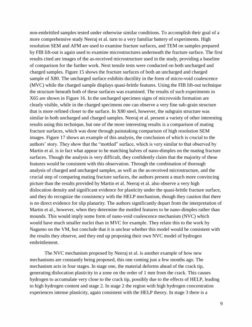
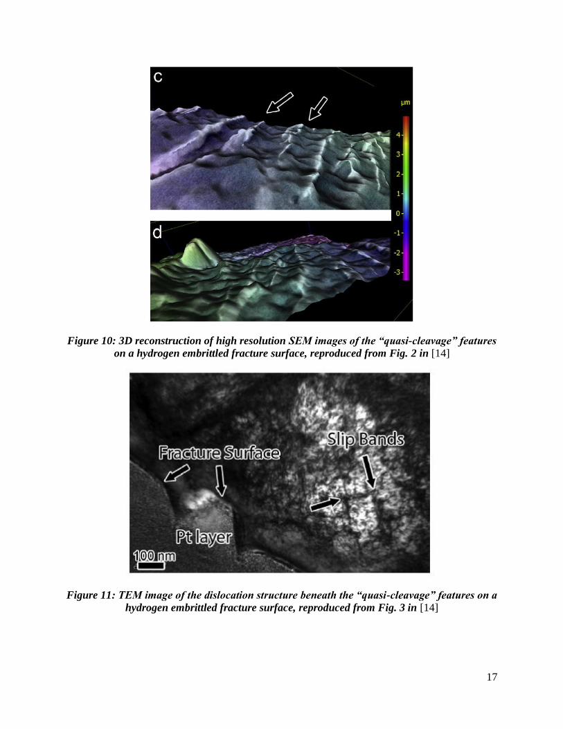
In a similar study Martin et al. focused on another common feature of hydrogen
embrittled fracture surfaces, known as “quasi-cleavage” [14]. Figure 9, below, shows an example
of a qausi-cleavage surface, characterized by the presence of “river markings.” They explain that
the river markings originate in the grain interior, and typically match ridge-to-ridge on opposing
fracture surfaces, but little is known about the underlying microstructure. By employing their
combination of high resolution SEM and FIB/TEM they are able to provide a closer look at these
river markings and the underlying dislocation structure, in Figure 10 and Figure 11, respectively.
While a detailed discussion on the formation of the river markings ensues, the key takeaway in
the context of this review is that, as Figure 11 shows, an extensive dislocation structure underlies
this feature, in much the same way as the flat regions discussed above. In addition, the
dislocations again appear to be of constant density as a function of distance from the surface.
The main conclusion reached by these studies is that contrary to intuition and previously
accepted assumptions, the relationship between deformation processes and the resulting fracture
surface cannot be determined from observations of the fracture surface alone, and must be
coupled with additional knowledge of the underlying microstructure. More specifically, the
underlying dislocation structure indicates that the assumption that flat regions on hydrogen
embrittled fracture surfaces resulted from decohesion alone is incorrect. Martin et al. argue that
the underlying dislocation structure shows that plasticity plays a crucial role in determining the
morphology of these fracture surface features, which are much more intricate than they appear in
low resolution SEM. The constant density of dislocations extending some distance into the
microstructure is a particularly important point, as both the AIDE and HEDE mechanisms would
likely result in the dislocation density being highest at the surface, and decreasing with distance
beneath the surface. In the case of AIDE this effect would be caused by the fact that adsorbed
hydrogen causes dislocation emission at the crack surface, which Martin et al. assume would
result in a gradient of dislocation density that decreases with distance from their origination at
the surface. In the case of HEDE, the dislocations would be explained as being a consequence of
a decohesion event rather than the cause. It would again be expected that the dislocation density
would be highest where the decohesion event occurred, causing the release of dislocations at the

6
fracture surface, and a decrease in dislocation density with distance from it. Conversely, in the
HELP mechanism, it is assumed that the dislocation structure is established well in advance of
the crack due to the increased dislocation motion caused by hydrogen. The pre-existing
dislocation structure caused by HELP would result in a high density of dislocations, which
would carry with them a high density of hydrogen, in a wide region in front of the crack. In other
words, the extensive dislocation network would be the cause rather than an effect of the
embrittlement, and would be expected to extend for a much longer distance. This would be
consistent with the constant-density dislocation structure observed, because the dislocation
network would be established ahead of the crack rather than emanating from it. The authors
conclude, based on the above, that the HELP mechanism is responsible for establishing the
dislocations structure in advance of the crack tip, and that the hydrogen associated with the high
density of dislocations reaches sufficient local levels to cause decohesion and the resulting crack
growth. A key take-away is that the crack is not propagating into a pristine microstructure, but
rather into a microstructure already severely altered by the presence of hydrogen. This suggests
that the old approaches to studying hydrogen embrittlement need to be re-evaluated, because the
condition of the sub-surface microstructure cannot be assumed based on features observed on the
fracture surface. Instead, approaches more like those used by the authors should be employed to
better establish the link between the microstructure and fracture mode.
While the authors deserve significant credit for demonstrating a process for better
correlating the microstructure and the fracture mode, there still remain significant questions
about the assumptions that are required to reach their conclusions. As alluded to earlier, one
detractor who believes that the authors’ logic is flawed is Lynch, a proponent of the AIDE
mechanism. Lynch provides strong comments questioning the interpretations and omissions of
Martin et al., starting with the fact that the samples the authors studied, which they obtained from
Dr. Brian Somerday, had been heat treated (20-30 min in air at 275 °C) after hydrogen assisted
cracking, but before final fracture, in a step meant to heat-tint the fracture surfaces and facilitate
the measurement of crack lengths [6]. This heat treatment was not mentioned by Martin et al.,
and Lynch argues that the omission calls into question the interpretation of both the fracture
surface features and the dislocation arrangements. Lynch argues that the heat treatment is bound
to modify the dislocation structure due to both thermally activated rearrangement/annihilation
and oxide-induced stresses. He also argues that the TEM foil preparation would modify the
dislocation structure to some degree, though the authors specifically state that this effect was
minimal. Lynch also provides references to multiple TEM investigations in which FIB and other
techniques are used to examine dislocation structures beneath fracture surfaces, and gradients in
dislocation density were observed. One such study, by Takahashi et al. examined fatigue in an
Fe-3.2 wt.% Si alloy, and concluded that the fatigue crack growth rate is promoted by hydrogen,
and shows a very localized dislocation distribution around the crack. Takahashi et al. actually
propose a mechanism that is very similar to AIDE, though without void growth due to the nature
of the cyclic loading [6], [15]. While it is possible that the constant density of dislocations
observed by Martin et al. is in fact a result of the HELP mechanism as they propose, Lynch

7
makes an important point, which is that because the morphology of the dislocation structure was
so central to their argument, they need to be more forthcoming about any sample preparation
steps that might affect the morphology, and explain why they believe that their conclusions
remain relevant in spite of these effects.
Another area in which the paper could be improved would have been the inclusion of
information regarding the mating fracture surfaces, for example whether ridges on mating
surfaces matched peak-to-peak, peak-to trough, or matched at all which could have important
implications in interpreting the fracture mode. The mounds are interpreted by the authors as
either a consequence of near-surface relaxation, or a reflection of the underlying dislocation
structure and local high hydrogen concentration [3]. Lynch argues that they could instead be
interpreted as shallow depressions, indicative of nanovoid coalescence processes, and he goes as
far as to cleave a steel sample (uncharged with hydrogen) and heat treat it in the manner
described above, to demonstrate the formation of a thin oxide layer which could somewhat
obscure the interpretation of these features. Such depressions could be attributed to the AIDE
merchanism, which as shown in Figure 1, below, involves the coalescence of the advancing
crack with voids forming ahead of the crack, leaving behind a series of these shallow depressions
which would be small enough in scale as to be invisible in standard SEM [6].
Lynch makes a variety of other arguments against the interpretation made by Martin et al.
In addition to pointing out the fact that the authors mischaracterize the AIDE mechanism, as
described earlier, he takes issue with the fact that they somewhat casually dismiss the similarities
between LME and hydrogen embrittlement. They indicate that they had performed studies on
liquid metal embrittled steels that suggest the embrittling processes are different than for
hydrogen, and that high resolution imaging of the fracture surface shows this, but the only
reference they provide is a conversation between the two authors (Martin and Robertson),
leaving this conclusion unable to be analyzed or verified by readers. While this point is not of the
utmost importance to the final conclusions reached, when taken into consideration along with
many of Lynch’s other arguments, a reasonably solid case can be made that the AIDE
mechanism should not be so quickly discounted here. On the whole, Martin et al. have shown
some that their techniques can provide valuable insight, and in view of what they have presented
their conclusions seem to be reasonably sound. Unfortunately there are enough questions raised
about the results that they would be well served by repeating some of their experiments on
better-controlled samples, such that their final conclusions would have a stronger backing.
In a more recent study by Martin, with Somerday and Ritchie, the same basic
experimental techniques are employed, but this time in a study of pure nickel (Ni-201) [16]. The
samples were thermally charged with hydrogen to approximately 2000 appm, and uniaxial
tension tests were conducted on 4 mm diameter samples. More detailed results on the effects of
hydrogen on the mechanical properties are reported by Bechtle et al. [17]. Figure 12 shows the
fully intergranular fracture surface observed, and Figure 13 shows a high resolution image of one
of the flat faces on the fracture surface, displaying an abundance of slip traces. In much the same

8
way as in their earlier paper, Martin et al. show that the surface is much more interesting than it
might seem with low resolution SEM alone. Again they extract samples using the FIB lift-out
technique to examine the dislocation structure beneath these features. Figure 14 shows the
location of one of the samples that was lifted out, as well as a TEM image showing a very
interesting dislocation structure underneath the surface, as well as an interesting steps on the
surface of the sample. The steps likely correspond to periodic extensive shearing of the grain
boundaries, and the underlying dislocations form 200-400 nm cells that roughly correspond to
the steps on the surface, though they do not match up in all instances. The authors also conclude
that the cracking is taking place in the grain boundaries rather than adjacent to grain boundaries,
because after taking many samples from the surface there was not an example of one in which a
grain boundary was observed just under the surface. In interpreting their results in terms of the
mechanisms of hydrogen embrittlement, one of the key questions is how the dislocation cells
form. The cell-structure that was observed is known to form in FCC metals and the size of the
cells is inversely proportional to the total strain. In high purity nickel Keller et al. measured a cell
size of 1.2 μm at 13% strain [18]. Martin et al. extrapolate this data to determine that the cell size
they observed would require 40% strain in samples uncharged by hydrogen. This is consistent
with the HELP mechanism, they say, because the dislocation motion was increased relative to
what would be expected in uncharged samples, essentially increasing the effective strain. In
addition, they explain that the transport of hydrogen by means of this increased dislocation
activity would be instrumental in achieving the high concentrations of hydrogen necessary to
establish the critical concentration needed to cause intergranular failure as described in [17]. The
authors propose that hydrogen drives the development of the complicated dislocation structure
observed, increasing the stress locally, depositing hydrogen on the grain boundary, and reaching
a critical hydrogen concentration at the grain boundary. This then leads to the observed
intergranular fracture by decohesion, with the grain boundary cohesive strength having been
reduced below that of the work-hardened matrix [16]. While Lynch would likely have an
alternative interpretation of these results, Martin et al. avoid some of the pitfalls that they fell
into with their previous paper, and they continue to prove the value of the experimental
procedure that they are championing.
Another example of a group using similar techniques to Martin et al. comes in a study by
Neeraj et al., again involving pipeline steels [13]. Specifically the study examines X65 and X80
steels which have been charged in high pressure hydrogen gas, creating a very similar material
system to that examined by Martin et al. in their 2011 study. As mentioned earlier, in their
introduction Neeraj et al. acknowledge the three major classes of hydrogen embrittlement
models, HEDE, HELP, and VM, leaving out any mention of AIDE, in another example of the
inconsistencies in what mechanisms are generally accepted to be the most credible. The authors
believe that there has been little systematic work done to compare deformation microstructures
in hydrogen charged and non-charged samples, which raises another issue with the work
presented by Martin et al. in their previous papers. While they did do some comparison of
dislocation cell sizes in their study of pure nickel, neither study showed a direct comparison to
9
non-embrittled samples tested under otherwise similar conditions. To accomplish their goal of a
more comprehensive study Neeraj et al. turn to a very familiar battery of experiments. High
resolution SEM and AFM are used to examine fracture surfaces, and TEM on samples prepared
by FIB lift-out is again used to examine microstructures underneath the fracture surface. The first
results cited are images of the as-received microstructure used in the study, providing a baseline
of comparison for the further work. Next tensile tests were conducted on both uncharged and
charged samples. Figure 15 shows the fracture surfaces of both an uncharged and charged
sample of X80. The uncharged surface exhibits ductility in the form of micro-void coalescence
(MVC) while the charged sample displays quasi-brittle features. Using the FIB lift-out technique
the structure beneath both of these surfaces was examined. The results of such experiments in
X65 are shown in Figure 16. In the uncharged specimen signs of microvoids formation are
clearly visible, while in the charged specimens one can observe a very fine sub-grain structure
that is more refined closer to the surface. In X80 steel, however, the subgrain structure was
similar in both uncharged and charged samples. Neeraj et al. present a variety of other interesting
results using this technique, but one of the more interesting results is a comparison of mating
fracture surfaces, which was done through painstaking comparison of high resolution SEM
images. Figure 17 shows an example of this analysis, the conclusion of which is crucial to the
authors’ story. They show that the “mottled” surface, which is very similar to that observed by
Martin et al. is in fact what appear to be matching halves of nano-dimples on the mating fracture
surfaces. Though the analysis is very difficult, they confidently claim that the majority of these
features would be consistent with this observation. Through the combination of thorough
analysis of charged and uncharged samples, as well as the as-received microstructure, and the
crucial step of comparing mating fracture surfaces, the authors present a much more convincing
picture than the results provided by Martin et al. Neeraj et al. also observe a very high
dislocation density and significant evidence for plasticity under the quasi-brittle fracture surface,
and they do recognize the consistency with the HELP mechanism, though they caution that there
is no direct evidence for slip planarity. The authors significantly depart from the interpretation of
Martin et al., however, when they determine the mottled features to be nano-dimples rather than
mounds. This would imply some form of nano-void coalescence mechanism (NVC) which
would have much smaller nuclei than in MVC for example. They relate this to the work by
Nagumo on the VM, but conclude that it is unclear whether this model would be consistent with
the results they observe, and they end up proposing their own NVC model of hydrogen
embrittlement.
The NVC mechanism proposed by Neeraj et al. is another example of how new
mechanisms are constantly being proposed, this one coming just a few months ago. The
mechanism acts in four stages. In stage one, the material deforms ahead of the crack tip,
generating dislocation plasticity in a zone on the order of 1 mm from the crack. This causes
hydrogen to accumulate very close to the crack tip, possibly due to the effects of HELP, leading
to high hydrogen content and stage 2. In stage 2 the region with high hydrogen concentration
experiences intense plasticity, again consistent with the HELP theory. In stage 3 there is a

10
generation of excess vacancies in this region, stabilized by the hydrogen in much the same way
as in the VM mechanism. Finally, in stage 4 sufficient excess vacancy concentration occurs to
cause the nucleation and growth of a nano-void, leading to eventual failure. This mechanism
would be consistent with the observations made in the study, as well as consistent with the HELP
and VM mechanisms as described, and with the HEDE mechanism in that there would be a need
for a critical hydrogen accumulation in a local volume [13]. Essentially the NVC mechanism
suggests that all of the other mechanisms have their role to play, but that no specific mechanism
is enough on its own to fully explain hydrogen embrittlement. Figure 18 shows a schematic of
the mechanism, along with a comparison to the mechanism proposed by Martin et al. illustrating
the difference that is made by the interpretation of the nano-dimples vs. mounds.
The massive body of work in hydrogen embrittlement in the nearly 150 years it has been
studied is daunting, and there is certainly no shortage of very good work being done in the field
to this day. As a result it is a great challenge to interpret the results in view of the many different
proposed mechanisms, and the whole process is made much more difficult by the fact that many
of the observed effects depend so strongly on material system and testing conditions, which are
highly variable across the many experiments performed. Martin et al. demonstrate that by using
the right combinations of experiments one can provide additional insights that would otherwise
be missed using more traditional analysis. They use this to examine both pipeline steels and pure
nickel, and provide useful insights into both material systems. Lynch fairly criticizes their work
for some of its crucial shortcomings, however. Some of these shortcomings are actively
detrimental towards their conclusions, such as their failure to disclose and account for the full
history of the samples that they were testing, calling into question some of the key results that
they observe. Other shortcomings are more forgivable, but nonetheless restrict their ability to
make important conclusions about their material systems. For example, the lack of comparison
between charged and uncharged samples hobbles their approach to an extent, because it leaves
them making assumptions about the difference between their samples and uncharged samples,
when the whole reason for their unique approach was to eliminate the need to make assumptions
and make direct observations of the effects they were interested in. Similarly, they ought to have
compared mating fracture surfaces. Through their use of the same battery of experiments, Neeraj
et al. both affirm the usefulness of Martin’s experimental approach, and confirm the major
shortcomings of it. They do so by using the same methods to conduct a significantly more
comprehensive study of similar material systems, demonstrating that Martin et al. quite possibly
misinterpreted their results on the crucial point of deciphering the “mottled” structure on the
fracture surface. Their ability to confirm that this structure is due to nano-dimples rather than
mounds informs an entirely new way of thinking about the hydrogen embrittlement process, and
leads to the proposal of a new mechanism that at the same time demonstrates both the continuing
innovation in the field, as well as the maturity of the field, as the mechanism turns out to very
nicely encapsulate the key concepts of the other more well-established mechanisms.

11
Figure 1: Schematics of (a) adsorbed hydrogen, (b) dislocation injection, and (c) dislocation
activity creating voids ahead of the crack, reproduced from Fig. 30 in [7]

12
Figure 2: Comparison of SEM images for (a) liquid mercury embrittlement and (b) hydrogen
embrittlement, both in single crystal nickel samples in the same orientation, reproduced from
Fig. 12 in [7]

13
Figure 3: The motion of dislocations upon the introduction and removal of hydrogen in an
environmental TEM, in high purity aluminum. Reproduced from Fig 6 in [10]

14
Figure 4: The motion of dislocations on the introduction of hydrogen in an environmental
TEM in Stainless Steel (310). Upon removal of hydrogen the dislocations remained pinned in
their new location. Reproduced from Figure 7 in [10]
Figure 5: SEM image of “flat, featureless” region, reproduced from Fig. 1 in [3]

15
Figure 6: High resolution SEM image of “flat, featureless” region showing high density of
mounds covering the surface, reproduced from Fig. 3 in [3]
Figure 7: AFM image of “flat, featureless” confirming the high density of mounds observed
covering the surface in high resolution SEM, reproduced from Fig. 4 in [3]

16
Figure 8: TEM images from beneath the surface of the “featureless” regions, showing a high
density of dislocations, at constant density more than 1 um under the surface, reproduced
from Fig. 5 in [3]
Figure 9: SEM images of the “quasi-cleavage” features on a hydrogen embrittled fracture
surface, reproduced from Fig. 1 in [14]
17
Figure 10: 3D reconstruction of high resolution SEM images of the “quasi-cleavage” features
on a hydrogen embrittled fracture surface, reproduced from Fig. 2 in [14]
Figure 11: TEM image of the dislocation structure beneath the “quasi-cleavage” features on a
hydrogen embrittled fracture surface, reproduced from Fig. 3 in [14]

18
Figure 12: SEM image of the fracture surface of a hydrogen charged Ni-201 sample
displaying fully intergranular failure. Reproduced from Fig. 1 in [16]
Figure 13: High resolution SEM image of one of the flat surfaces on the intergranlar fracture
surface in Figure 12, showing abundant slip lines. Reproduced from Fig. 2 in [16]

19
Figure 14: High resolution SEM image (a) showing the deposition of a platinum strip on the
surface of the slip bands prior to FIB lift-out. TEM image (b) of sample extracted from
underneath the Pt strip shown in (a). The dark area on top of the image is the platinum, and
the arrows show the ridges on the sample surface. Reproduced from Fig. 4 in [16]
Figure 15: SEM images showing (a) ductile failure in an uncharged sample of X80, and (b)
quasi-brittle failure in a hydrogen charged sample of the same alloy. Reproduced from Fig. 2
in [13]
Figure 16: TEM images of samples taken from just underneath the fracture surface in
uncharged X65 samples (a),(b) and charged samples (c),(d),(e). Reproduced from Fig. 3 in
[13]

20
Figure 17: High resolution SEM of “mottled” surface on quasi-brittle facets from mating
fracture surfaces, in which features are identified as corresponding halves of nano-dimples on
the surface. Adapted from Fig. 9 in [13]
Figure 18: Schematic illustrating the NVC mechanism of hydrogen embrittlement. Adapted
from Fig. 12 in [13].
21
Reference List
[1] W. H. Johnson, “On Some Remarkable Changes Produced in Iron and Steel by the Action
of Hydrogen and Acids,” Proceedings of the Royal Society of London, p. 393, 1875.
[2] S. P. Lynch, “Mechanisms and Kinetics of Environmentally Assisted Cracking: Current
Status, Issues, and Suggestions for Further Work,” Metallurgical and Materials
Transactions A, Sep. 2012.
[3] M. L. Martin, I. M. Robertson, and P. Sofronis, “Interpreting hydrogen-induced fracture
surfaces in terms of deformation processes: A new approach,” Acta Materialia, vol. 59,
no. 9, pp. 3680–3687, May 2011.
[4] W. W. Gerberich, R. A. Oriani, M. Lji, and X. Chen, “The necessity of both plasticity and
brittleness in the fracture thresholds of iron,” Philosophical Magazine A, vol. 63, no. 2,
pp. 363–376, 1991.
[5] R. A. Oriani and P. H. Josephic, “Hydrogen-Enhanced Load Relaxation in a Deformed
Medium-Carbon Steel,” Acta Metallurgica, vol. 27, pp. 997–1005, 1979.
[6] S. P. Lynch, “Interpreting hydrogen-induced fracture surfaces in terms of deformation
processes: A new approach,” Scripta Materialia, vol. 65, no. 10, pp. 851–854, Nov. 2011.
[7] S. P. Lynch, “Environmentally assisted cracking: Overview of evidence for an adsorption-
induced localised-slip process,” Acta Metallurgica, vol. 36, no. 10, pp. 2639–2661, Oct.
1988.
[8] I. M. Robertson, “The effect of hydrogen on dislocation dynamics,” Engineering Fracture
Mechanics, vol. 68, no. 6, pp. 671–692, Apr. 2001.
[9] I. M. Robertson, D. Lillig, and P. J. Ferreira, “Revealing the Fundamental Processes
Controlling Hydrogen Embrittlement,” ASM International, 2009, pp. 22–37.
[10] P. J. Ferreira, I. M. Robertson, and H. K. Birnbaum, “Hydrogen effects on the interaction
between dislocations,” Acta Materialia, vol. 46, no. 5, pp. 1749–1757, Mar. 1998.
[11] T. C. Lee, D. K. Dewald, J. a. Eades, I. M. Robertson, and H. K. Birnbaum, “An
environmental cell transmission electron microscope,” Review of Scientific Instruments,
vol. 62, no. 6, p. 1438, 1991.
[12] M. Nagumo, “Hydrogen related failure of steels – a new aspect,” Materials Science and
Technology, vol. 20, no. 8, pp. 940–950, Aug. 2004.

22
[13] T. Neeraj, R. Srinivasan, and J. Li, “Hydrogen embrittlement of ferritic steels:
Observations on deformation microstructure, nanoscale dimples and failure by
nanovoiding,” Acta Materialia, vol. 60, no. 13–14, pp. 5160–5171, Aug. 2012.
[14] M. L. Martin, J. A. Fenske, G. S. Liu, P. Sofronis, and I. M. Robertson, “On the formation
and nature of quasi-cleavage fracture surfaces in hydrogen embrittled steels,” Acta
Materialia, vol. 59, no. 4, pp. 1601–1606, Feb. 2011.
[15] Y. Takahashi, M. Tanaka, K. Higashida, K. Yamaguchi, and H. Noguchi, “An intrinsic
effect of hydrogen on cyclic slip deformation around a {110} fatigue crack in Fe–3.2wt.%
Si alloy,” Acta Materialia, vol. 58, no. 6, pp. 1972–1981, Apr. 2010.
[16] M. L. Martin, B. P. Somerday, R. O. Ritchie, P. Sofronis, and I. M. Robertson,
“Hydrogen-induced intergranular failure in nickel revisited,” Acta Materialia, vol. 60, no.
6–7, pp. 2739–2745, Apr. 2012.
[17] S. Bechtle, M. Kumar, B. P. Somerday, M. E. Launey, and R. O. Ritchie, “Grain-
boundary engineering markedly reduces susceptibility to intergranular hydrogen
embrittlement in metallic materials,” Acta Materialia, vol. 57, no. 14, pp. 4148–4157,
Aug. 2009.
[18] C. Keller, E. Hug, R. Retoux, and X. Feaugas, “TEM study of dislocation patterns in near-
surface and core regions of deformed nickel polycrystals with few grains across the cross
section,” Mechanics of Materials, vol. 42, no. 1, pp. 44–54, Jan. 2010.