jenbacher gasm bhkw en
DESCRIPTION
BrosuraTRANSCRIPT
C O G E N E R A T I O N W I T H G A S E N G I N E S

2
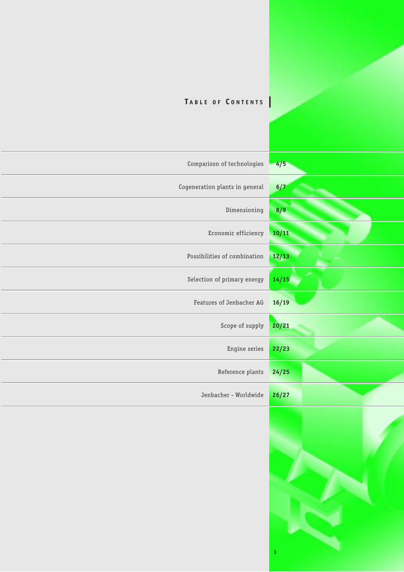
Comparison of technologies 4/5
Cogeneration plants in general 6/7
Dimensioning 8/9
Economic eff iciency 10/11
Possibilities of combination 12/13
Selection of primary energy 14/15
Features of Jenbacher AG 16/19
Scope of supply 20/21
Engine series 22/23
Reference plants 24/25
Jenbacher - Worldwide 26/27
T A B L E O F C O N T E N T S
3
4
C O M P A R I S O N O F T E C H N O L O G I E S
Increased ecological consciousness and the knowledge of the limited
reserves of primary energy in the form of fossil fuels make it necessary to
transform available energy sources economically. Cogeneration plants produce
electricity and heat at decentralized locations, i.e. where they are required.
They of fer optimal ef f iciency in the transformation of energy with minimum
environmental pollution.
Losses usually result from waste heat. For that reason, sensible,
thermodynamic energy converters are those which supply power (usually used to
produce electricity) and heat. This power, however, can also be utilized for the direct
drive of machines such as pumps, compressors (e.g. for refrigerating plants), etc.
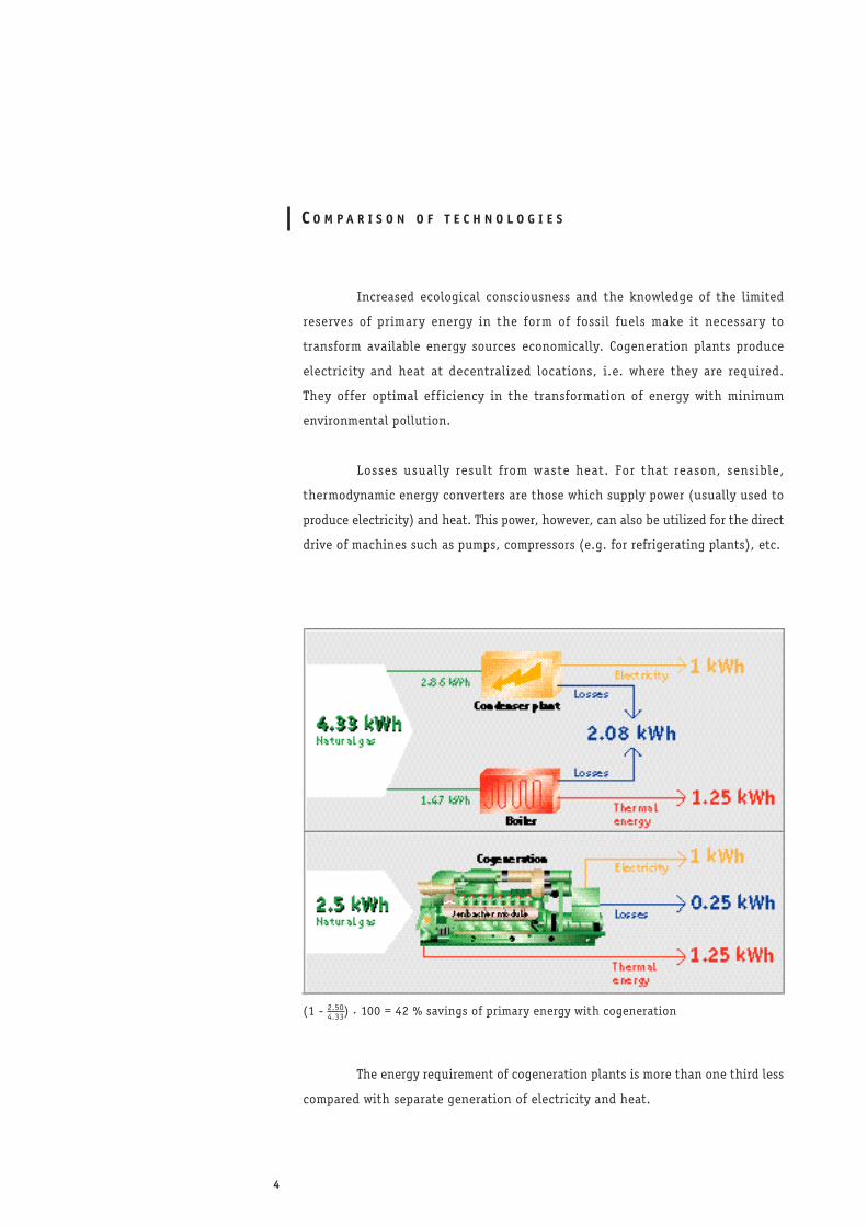
The energy requirement of cogeneration plants is more than one third less
compared with separate generation of electricity and heat.
(1 - 4.33) . 100 = 42 % savings of primary energy with cogeneration2.50
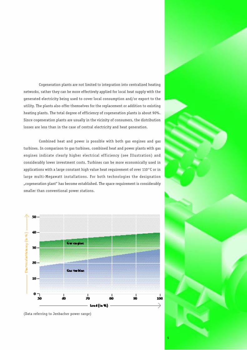
(Data referring to Jenbacher power range)
Cogeneration plants are not limited to integration into centralized heating
networks, rather they can be more effectively applied for local heat supply with the
generated electricity being used to cover local consumption and/or export to the
utility. The plants also offer themselves for the replacement or addition to existing
heating plants. The total degree of efficiency of cogeneration plants is about 90%.
Since cogeneration plants are usually in the vicinity of consumers, the distribution
losses are less than in the case of central electricity and heat generation.
Combined heat and power is possible with both gas engines and gas
turbines. In comparison to gas turbines, combined heat and power plants with gas
engines indicate clearly higher electrical ef f iciency (see Illustration) and
considerably lower investment costs. Turbines can be more economically used in
applications with a large constant high value heat requirement of over 110°C or in
large multi-Megawatt installations. For both technologies the designation
„cogeneration plant“ has become established. The space requirement is considerably
smaller than conventional power stations.
5
6
Construct ion - manner
of operat ion - integrat ion
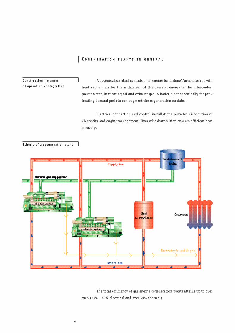
Scheme of a cogenerat ion plant
C O G E N E R A T I O N P L A N T S I N G E N E R A L
A cogeneration plant consists of an engine (or turbine)/generator set with
heat exchangers for the utilization of the thermal energy in the intercooler,
jacket water, lubricating oil and exhaust gas. A boiler plant specif ically for peak
heating demand periods can augment the cogeneration modules.
Electrical connection and control installations serve for distribution of
electricity and engine management. Hydraulic distribution ensures eff icient heat
recovery.
The total eff iciency of gas engine cogeneration plants attains up to over
90% (30% - 40% electrical and over 50% thermal).
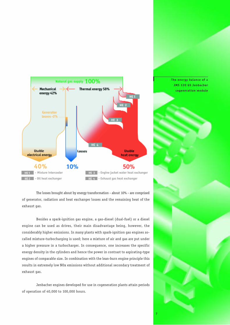
The losses brought about by energy transformation - about 10% - are comprised
of generator, radiation and heat exchanger losses and the remaining heat of the
exhaust gas.
Besides a spark-ignition gas engine, a gas-diesel (dual-fuel) or a diesel
engine can be used as drives, their main disadvantage being, however, the
considerably higher emissions. In many plants with spark-ignition gas engines so-
called mixture-turbocharging is used; here a mixture of air and gas are put under
a higher pressure in a turbocharger. In consequence, one increases the specif ic
energy density in the cylinders and hence the power in contrast to aspirating-type
engines of comparable size. In combination with the lean-burn engine principle this
results in extremely low NOx emissions without additional secondary treatment of
exhaust gas.
Jenbacher engines developed for use in cogeneration plants attain periods
of operation of 40,000 to 100,000 hours.
The energy balance of a
JMS 320 GS Jenbacher
cogenerat ion module
- Mixture intercooler
- Oil heat exchanger
- Engine jacket water heat exchanger
- Exhaust gas heat exchanger
7
8
D I M E N S I O N I N G
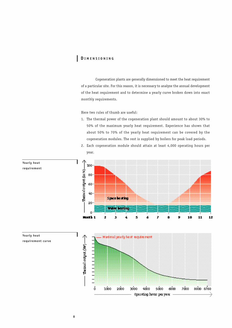
Cogeneration plants are generally dimensioned to meet the heat requirement
of a particular site. For this reason, it is necessary to analyze the annual development
of the heat requirement and to determine a yearly curve broken down into exact
monthly requirements.
Here two rules of thumb are useful:
1. The thermal power of the cogeneration plant should amount to about 30% to
50% of the maximum yearly heat requirement. Experience has shown that
about 50% to 70% of the yearly heat requirement can be covered by the
cogeneration modules. The rest is supplied by boilers for peak load periods.
2. Each cogeneration module should attain at least 4,000 operating hours per
year.
Year ly heat
requirement
Year ly heat
requirement curve
Hot water for domestic requirements and other uses show here a higher
portion of base load. New housing developments are characterized by good thermal
insulation, so that no strongly pronounced peak load periods develop.
A uniform base heat load and high electricity consumption form for
these customers the ideal prerequisites for the use of cogeneration plants. In
addition to this, they can also be utilized for the supply of emergency power.
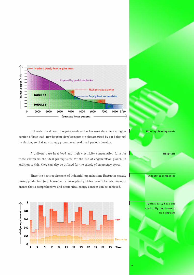
Since the heat requirement of industrial organizations f luctuates greatly
during production (e.g. breweries), consumption profiles have to be determined to
ensure that a comprehensive and economical energy concept can be achieved.
Housing developments
Hospita ls
Industr ia l companies
Typica l dai ly heat and
e lectr ic i ty requirement
in a brewer y
9
10
E C O N O M I C E F F I C I E N C Y
To document the economic efficiency of a cogeneration plant, one contrasts
savings and returns resulting from the production of electricity and heat with
investment costs.
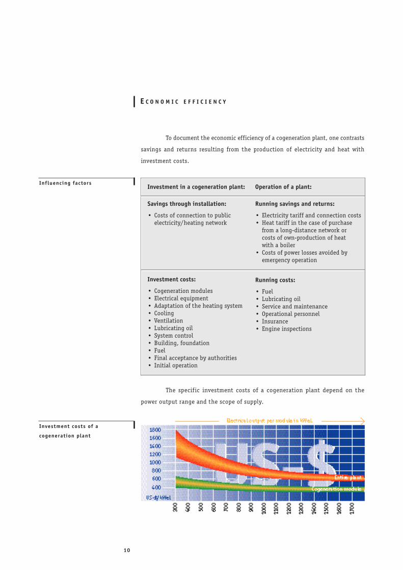
The specif ic investment costs of a cogeneration plant depend on the
power output range and the scope of supply.
Inf luencing factors
Investment costs of a
cogenerat ion plant
Operation of a plant:
Running savings and returns:
• Electricity tariff and connection costs• Heat tariff in the case of purchase
from a long-distance network or costs of own-production of heatwith a boiler
• Costs of power losses avoided by emergency operation
Running costs:
• Fuel• Lubricating oil• Service and maintenance• Operational personnel• Insurance• Engine inspections
Investment in a cogeneration plant:
Savings through installation:
• Costs of connection to public electricity/heating network
Investment costs:
• Cogeneration modules• Electrical equipment• Adaptation of the heating system• Cooling• Ventilation• Lubricating oil• System control• Building, foundation• Fuel• Final acceptance by authorities• Initial operation
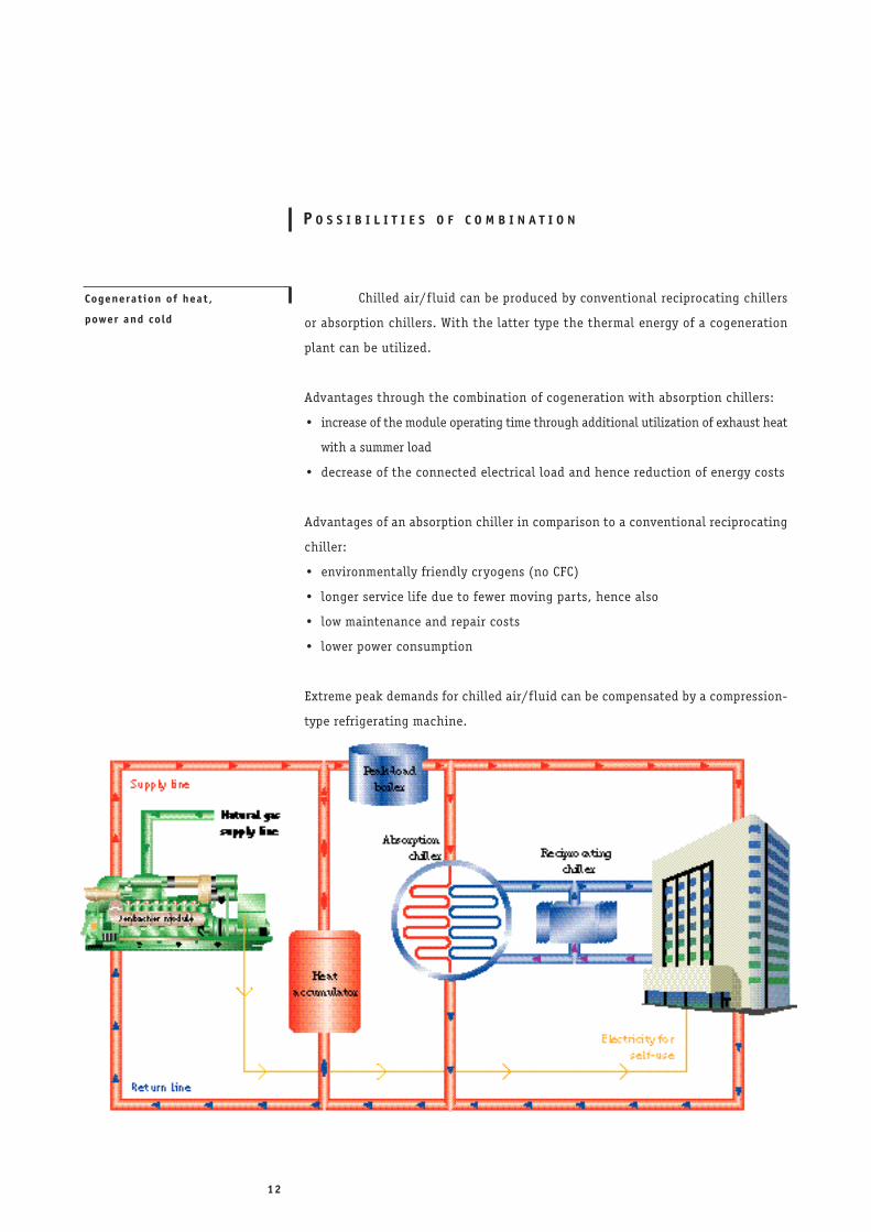
The primary criteria for the economical operation of a plant is the assess-
ment of the generated electricity. This can be utilized for either the plant‘s own
requirements or be fed into the public grid.
The f irst option above is economically more interesting. In this way the
electricity power prices which are saved can also be credited to one‘s account.
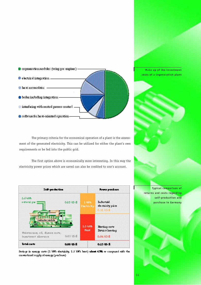
Make up of the investment
costs of a cogenerat ion plant
Typica l comparison of
returns and costs regarding
se l f-product ion and
purchase in Germany
11
12
P O S S I B I L I T I E S O F C O M B I N A T I O N
Cogenerat ion of heat ,
power and cold
Chilled air/f luid can be produced by conventional reciprocating chillers
or absorption chillers. With the latter type the thermal energy of a cogeneration
plant can be utilized.
Advantages through the combination of cogeneration with absorption chillers:
• increase of the module operating time through additional utilization of exhaust heat
with a summer load
• decrease of the connected electrical load and hence reduction of energy costs
Advantages of an absorption chiller in comparison to a conventional reciprocating
chiller:
• environmentally friendly cryogens (no CFC)
• longer service life due to fewer moving parts, hence also
• low maintenance and repair costs
• lower power consumption
Extreme peak demands for chilled air/f luid can be compensated by a compression-
type refrigerating machine.
Hot-cool ing
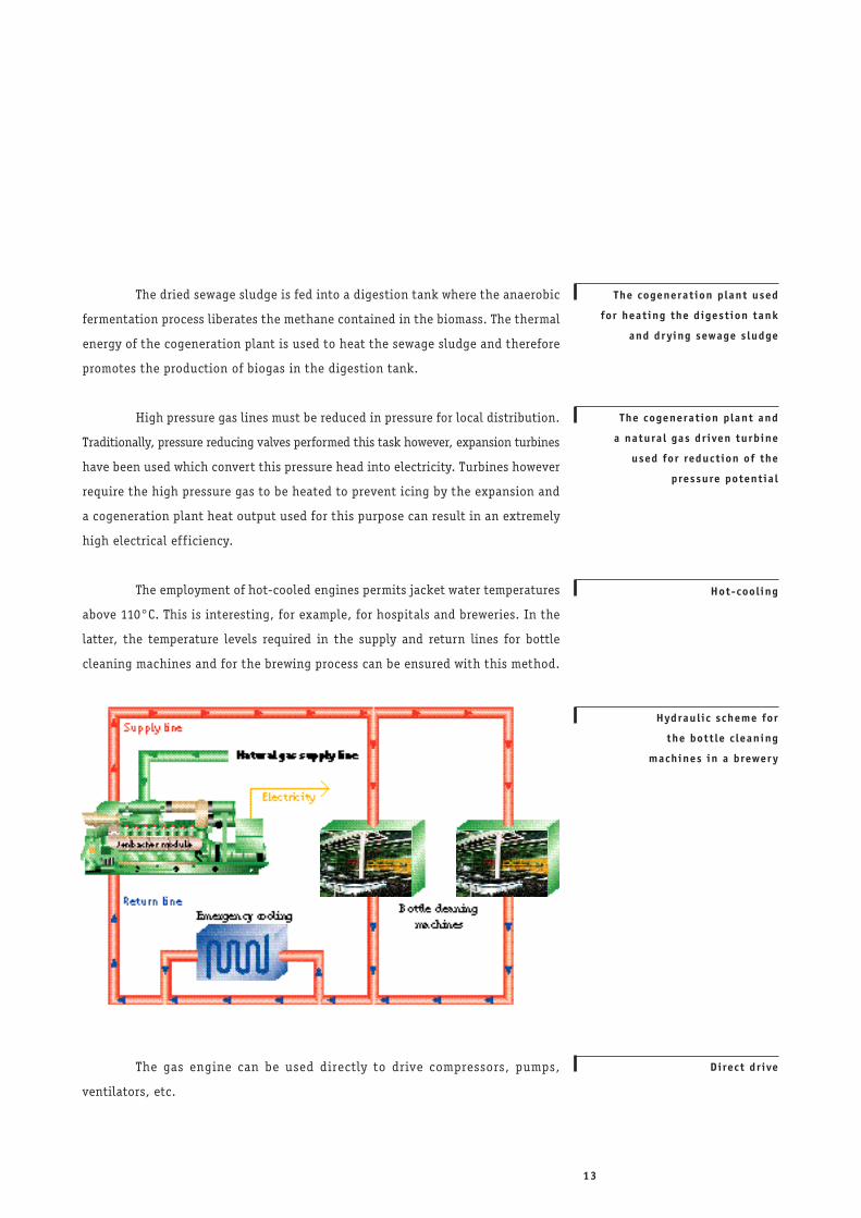
Hydraul ic scheme for
the bott le c leaning
machines in a brewer y
The cogenerat ion plant used
for heat ing the digest ion tank
and dr y ing sewage s ludge
Direct dr ive
The cogenerat ion plant and
a natural gas dr iven turbine
used for reduct ion of the
pressure potentia l
The dried sewage sludge is fed into a digestion tank where the anaerobic
fermentation process liberates the methane contained in the biomass. The thermal
energy of the cogeneration plant is used to heat the sewage sludge and therefore
promotes the production of biogas in the digestion tank.
High pressure gas lines must be reduced in pressure for local distribution.
Traditionally, pressure reducing valves performed this task however, expansion turbines
have been used which convert this pressure head into electricity. Turbines however
require the high pressure gas to be heated to prevent icing by the expansion and
a cogeneration plant heat output used for this purpose can result in an extremely
high electrical ef f iciency.
The employment of hot-cooled engines permits jacket water temperatures
above 110°C. This is interesting, for example, for hospitals and breweries. In the
latter, the temperature levels required in the supply and return lines for bottle
cleaning machines and for the brewing process can be ensured with this method.
The gas engine can be used directly to drive compressors, pumps,
ventilators, etc.
13
14
S E L E C T I O N O F P R I M A R Y E N E R G Y
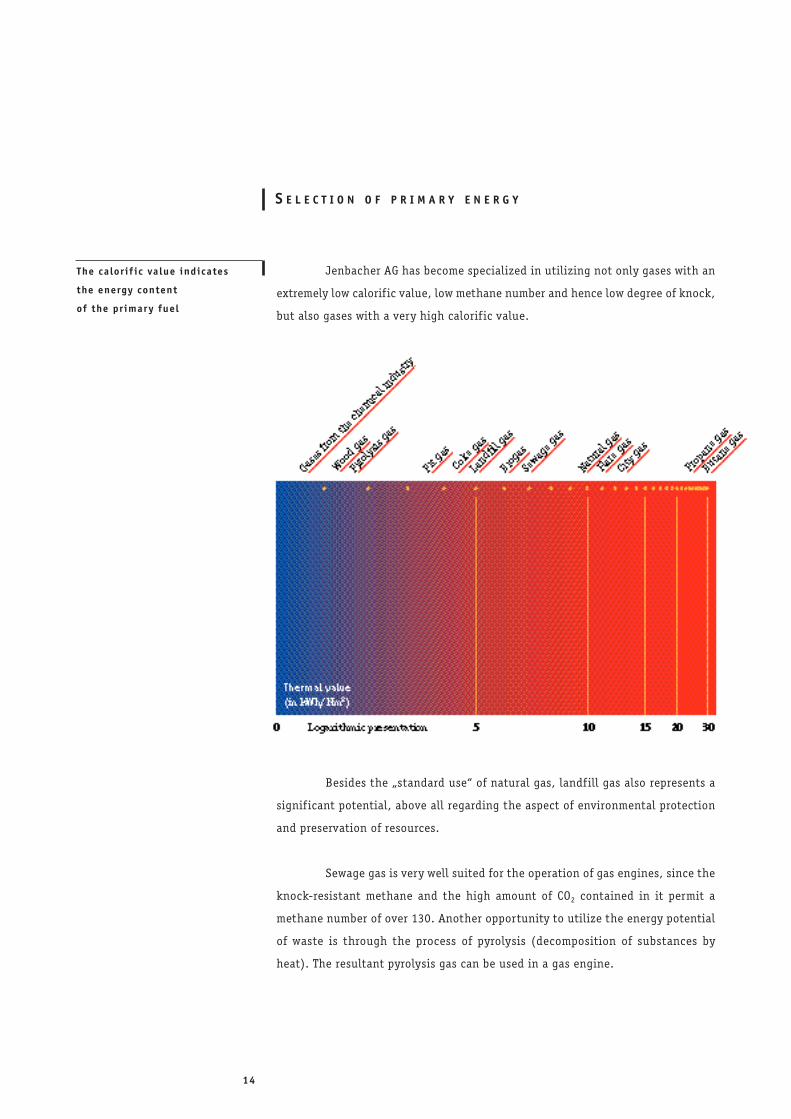
Jenbacher AG has become specialized in utilizing not only gases with an
extremely low calorific value, low methane number and hence low degree of knock,
but also gases with a very high calorif ic value.
Besides the „standard use“ of natural gas, landfill gas also represents a
signif icant potential, above all regarding the aspect of environmental protection
and preservation of resources.
Sewage gas is very well suited for the operation of gas engines, since the
knock-resistant methane and the high amount of CO2 contained in it permit a
methane number of over 130. Another opportunity to utilize the energy potential
of waste is through the process of pyrolysis (decomposition of substances by
heat). The resultant pyrolysis gas can be used in a gas engine.
The ca lor i f ic va lue indicates
the energy content
of the pr imar y fuel
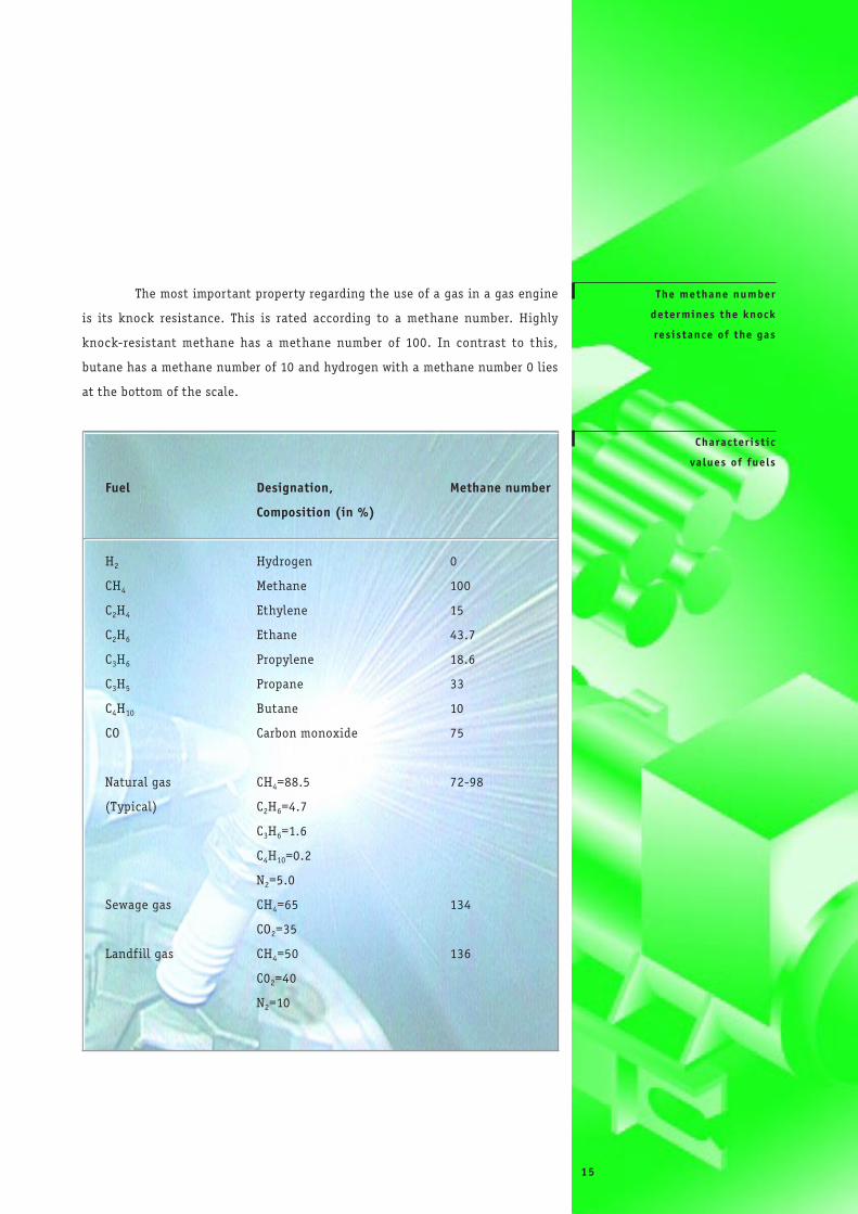
The most important property regarding the use of a gas in a gas engine
is its knock resistance. This is rated according to a methane number. Highly
knock-resistant methane has a methane number of 100. In contrast to this,
butane has a methane number of 10 and hydrogen with a methane number 0 lies
at the bottom of the scale.
The methane number
determines the knock
res istance of the gas
Character ist ic
va lues of fuels
Fuel Designation, Methane number
Composition (in %)
H2 Hydrogen 0
CH4 Methane 100
C2H4 Ethylene 15
C2H6 Ethane 43.7
C3H6 Propylene 18.6
C3H5 Propane 33
C4H10 Butane 10
CO Carbon monoxide 75
Natural gas CH4=88.5 72-98
(Typical) C2H6=4.7
C3H6=1.6
C4H10=0.2
N2=5.0
Sewage gas CH4=65 134
CO2=35
Landfill gas CH4=50 136
C02=40
N2=10
15
16
F E A T U R E S O F J E N B A C H E R A G
Jenbacher AG can look back at more than four decades of experience in
the construction of gas engines. Thousands of modules for various applications have
been installed within this period of time all over the world. In Europe alone,
Jenbacher can proudly claim to have the largest number of installed cogeneration
modules with a very low-emission combustion process.
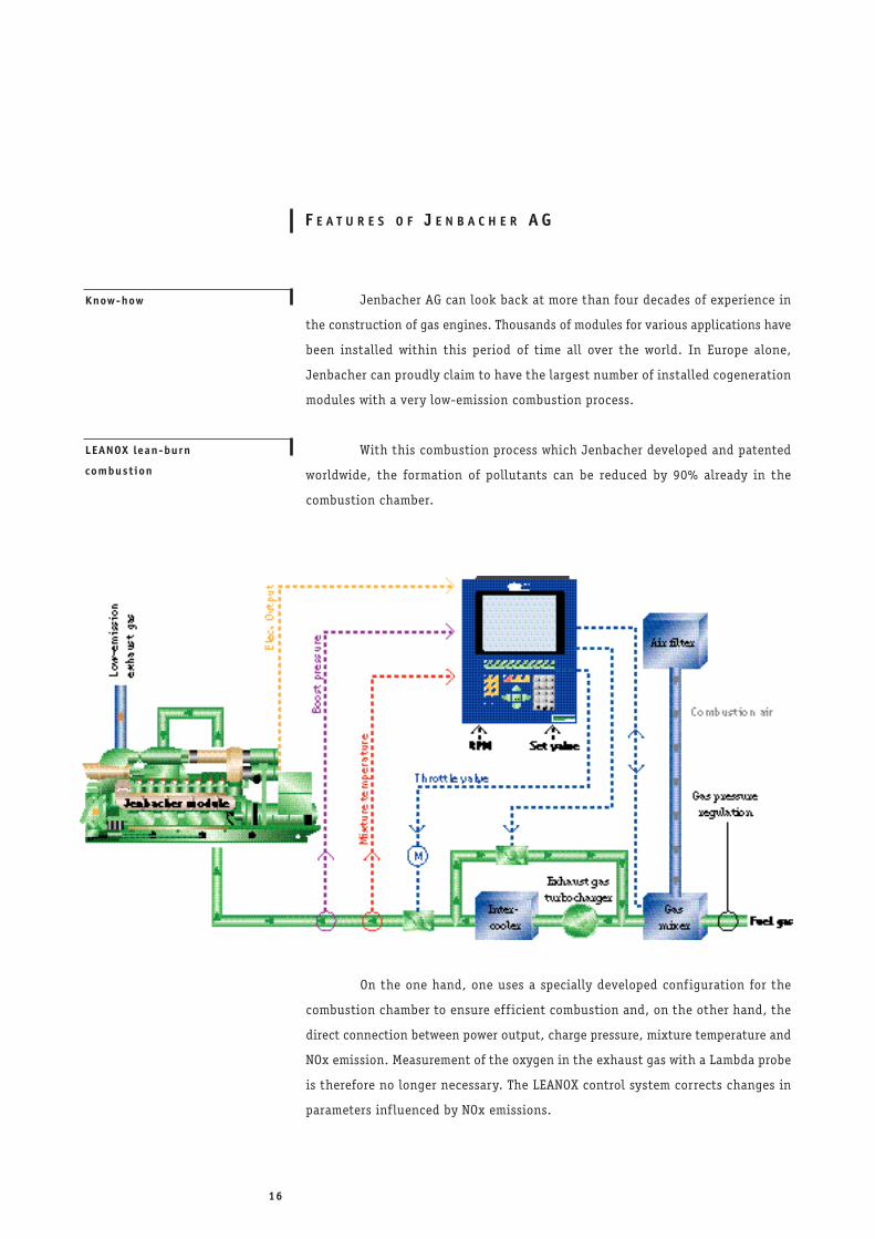
With this combustion process which Jenbacher developed and patented
worldwide, the formation of pollutants can be reduced by 90% already in the
combustion chamber.
LEANOX lean-burn
combustion
Know-how
On the one hand, one uses a specially developed configuration for the
combustion chamber to ensure eff icient combustion and, on the other hand, the
direct connection between power output, charge pressure, mixture temperature and
NOx emission. Measurement of the oxygen in the exhaust gas with a Lambda probe
is therefore no longer necessary. The LEANOX control system corrects changes in
parameters inf luenced by NOx emissions.
Exhaust gas
turbocharger bypass
Jenbacher gas mixer
Optimal e lectr ica l ef f ic iency
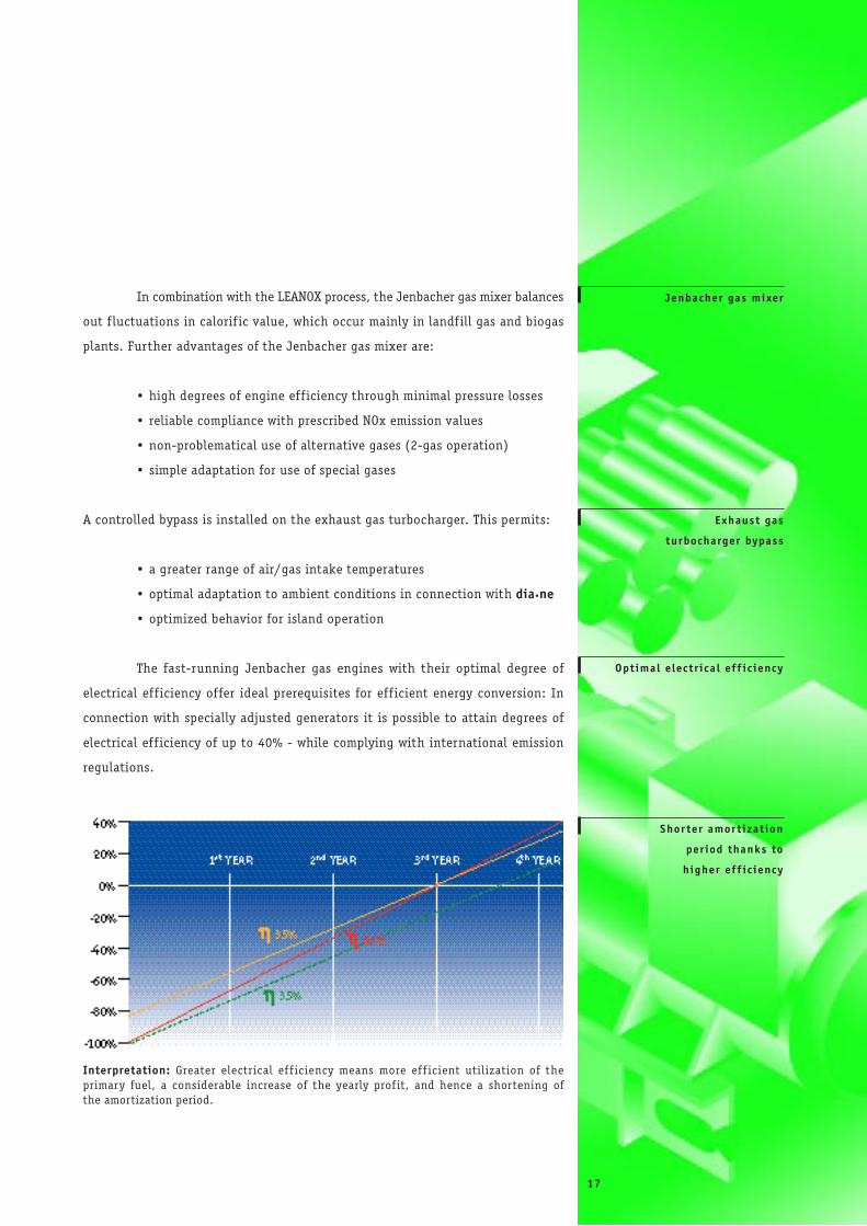
Shor ter amor t izat ion
per iod thanks to
higher ef f ic iency
Interpretation: Greater electrical ef f iciency means more ef f icient utilization of the primary fuel, a considerable increase of the yearly prof it, and hence a shortening of the amortization period.
In combination with the LEANOX process, the Jenbacher gas mixer balances
out f luctuations in calorif ic value, which occur mainly in landfill gas and biogas
plants. Further advantages of the Jenbacher gas mixer are:
• high degrees of engine eff iciency through minimal pressure losses
• reliable compliance with prescribed NOx emission values
• non-problematical use of alternative gases (2-gas operation)
• simple adaptation for use of special gases
A controlled bypass is installed on the exhaust gas turbocharger. This permits:
• a greater range of air/gas intake temperatures
• optimal adaptation to ambient conditions in connection with dia.ne
• optimized behavior for island operation
The fast-running Jenbacher gas engines with their optimal degree of
electrical eff iciency offer ideal prerequisites for eff icient energy conversion: In
connection with specially adjusted generators it is possible to attain degrees of
electrical eff iciency of up to 40% - while complying with international emission
regulations.
17
18
• the lowest CO/hydrocarbons, formaldehyde and CH4 emissions
• higher specif ic power output
• higher eff iciency
• minimal NOx emissions
• clear increase in specif ic power output
• maximal service life of the spark plugs
• optimal eff iciency
Electronic engine
management system
Systems for secondar y
t reatment of exhaust gases
andThermal af tertreatment of exhaust landfill gas
SCR catalytic converter for natural gas
Shie lded ignit ion system The high ignition voltages of gas engines generate electromagnetic
interference. To prevent this, Jenbacher developed a shielded ignition system. This
permits compliance with CE regulations with regard to electromagnetic compatibility
(EMC) and means that there is no problem utilizing Jenbacher plants in
residential areas. At the same time, the sensitivity of the ignition system to
external disturbances is reduced.
Speed control, power output control and combustion control must be
optimally coordinated for the operation of a cogeneration plant. This function is
performed by the dia.ne system - developed by Jenbacher of course - which places
great importance on user-friendly operation. A color graphic display permits an
user-friendly presentation of all relevant data. The multi-color trend display, the
alarm management function and the possibility of long-distance data transmission
all guarantee the ease of servicing the plant.
Cyl inder head serv ice l i fe
Service
Spark p lugs
Jenbacher offers its customers individually adapted maintenance contracts,
depending on whether they already have their own service and maintenance
personnel or not. Above and beyond this, Jenbacher‘s comprehensive training
program ensures that the customer is kept up to date on the latest plant-specif ic
details.
The following examples document the customer orientation of the
Jenbacher service organization:
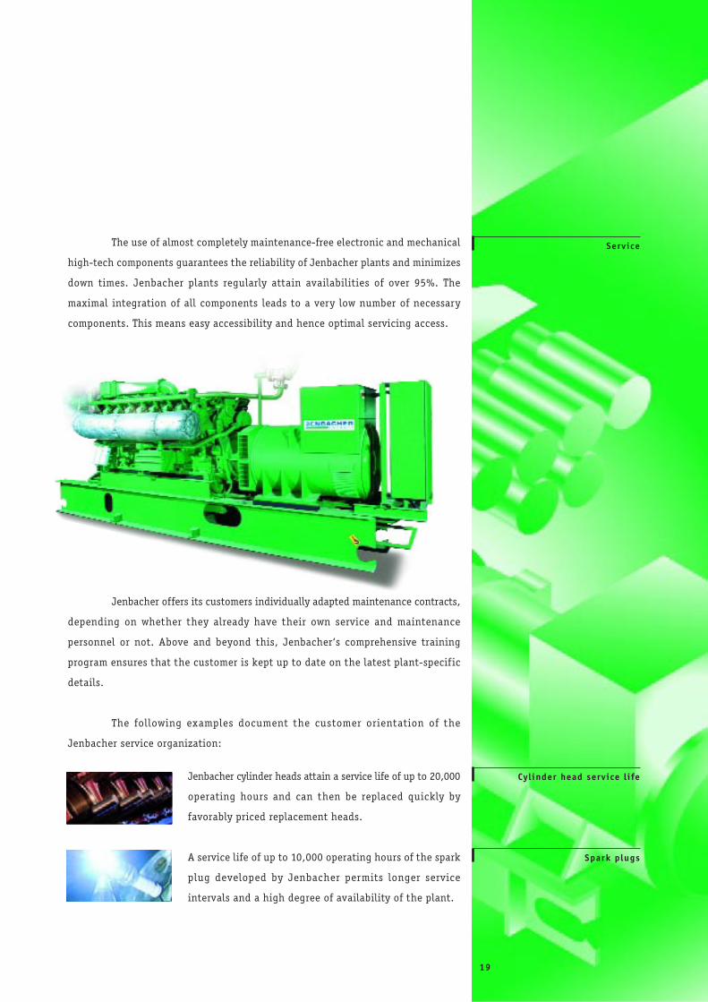
The use of almost completely maintenance-free electronic and mechanical
high-tech components guarantees the reliability of Jenbacher plants and minimizes
down times. Jenbacher plants regularly attain availabilities of over 95%. The
maximal integration of all components leads to a very low number of necessary
components. This means easy accessibility and hence optimal servicing access.
Jenbacher cylinder heads attain a service life of up to 20,000
operating hours and can then be replaced quickly by
favorably priced replacement heads.
A service life of up to 10,000 operating hours of the spark
plug developed by Jenbacher permits longer service
intervals and a high degree of availability of the plant.
19
20
S C O P E O F S U P P L Y
All Jenbacher modules are suited to the specific wishes and requirements
of the customer, tested as completely assembled modules regarding function and
performance, and then delivered to their f inal location.
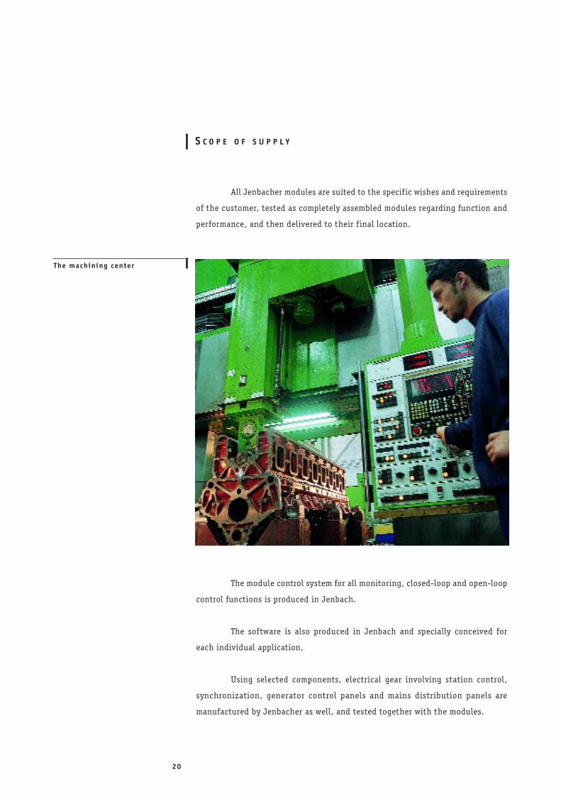
The module control system for all monitoring, closed-loop and open-loop
control functions is produced in Jenbach.
The software is also produced in Jenbach and specially conceived for
each individual application.
Using selected components, electrical gear involving station control,
synchronization, generator control panels and mains distribution panels are
manufactured by Jenbacher as well, and tested together with the modules.
The machining center
Each individual user-specific feature is integrated already in the planning
phase, as is the consideration of local conditions. All peripheral plant components
are produced to meet respective requirements.
In the preparation of the complete concept and of profitability calculations
Jenbacher acts as both planner and advisor. In addition, we support our partners
in the selection of suitable f inancing models.
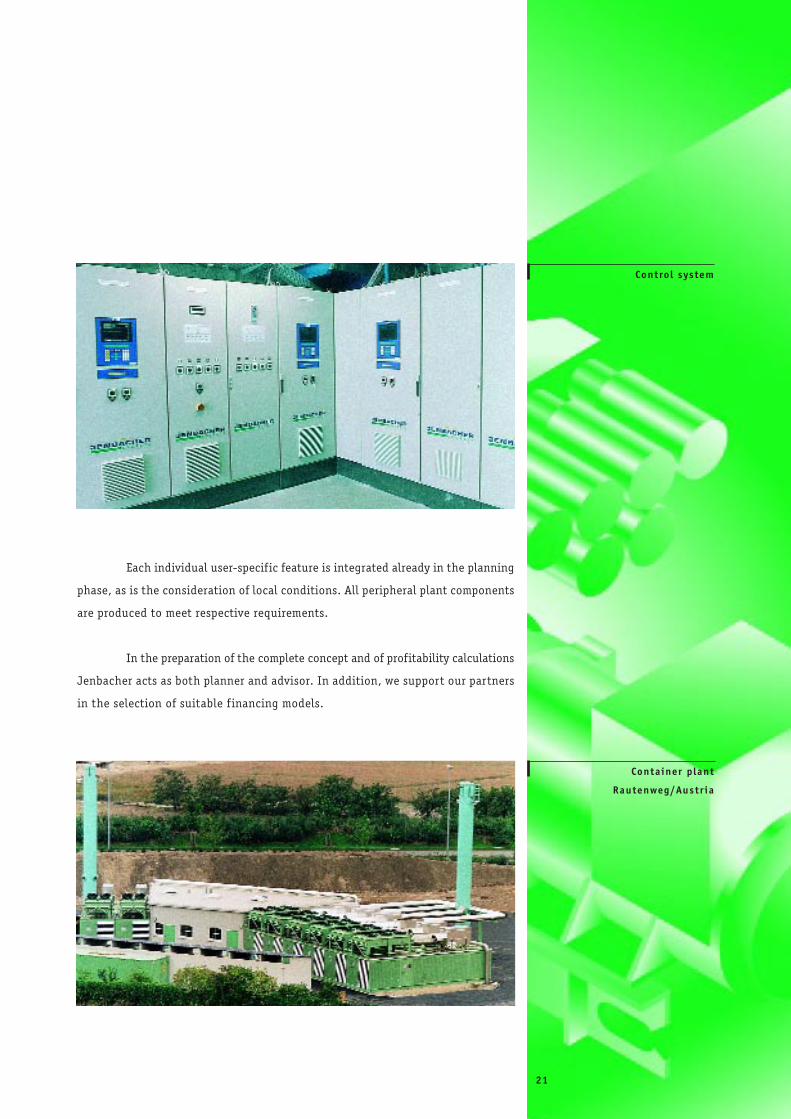
Control system
Container p lant
Rautenweg/Austr ia
21
1
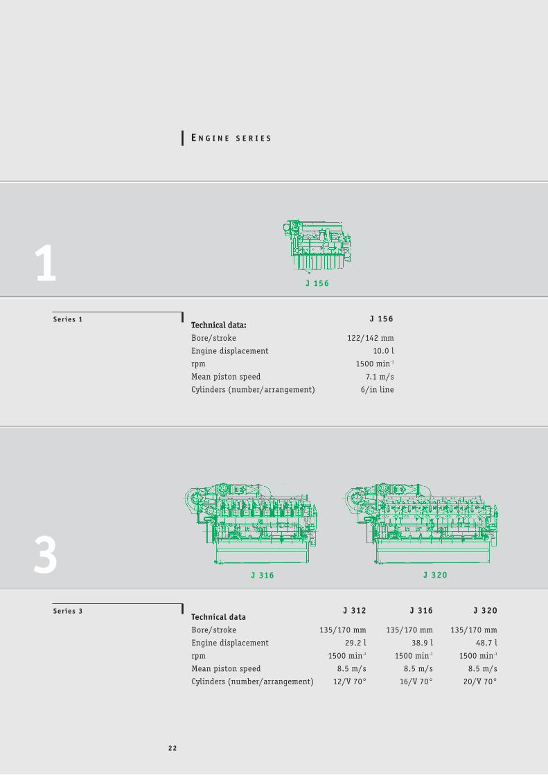
E N G I N E S E R I E S
Technical data:Bore/stroke 122/142 mm
Engine displacement 10.0 l
rpm 1500 min-1
Mean piston speed 7.1 m/s
Cylinders (number/arrangement) 6/in line
Technical dataBore/stroke 135/170 mm 135/170 mm 135/170 mm
Engine displacement 29.2 l 38.9 l 48.7 l
rpm 1500 min-1 1500 min-1 1500 min-1
Mean piston speed 8.5 m/s 8.5 m/s 8.5 m/s
Cylinders (number/arrangement) 12/V 70° 16/V 70° 20/V 70°
J 156
J 320J 316J 312
J 316 J 3203Series 3
Ser ies 1
J 156
22
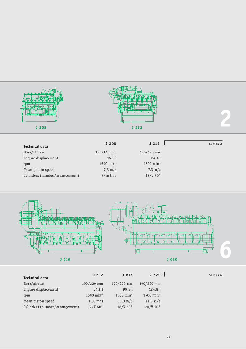
Ser ies 6
Ser ies 2Technical dataBore/stroke 135/145 mm 135/145 mm
Engine displacement 16.6 l 24.4 l
rpm 1500 min-1 1500 min-1
Mean piston speed 7.3 m/s 7.3 m/s
Cylinders (number/arrangement) 8/in line 12/V 70°
Technical dataBore/stroke 190/220 mm 190/220 mm 190/220 mm
Engine displacement 74.9 l 99.8 l 124.8 l
rpm 1500 min-1 1500 min-1 1500 min-1
Mean piston speed 11.0 m/s 11.0 m/s 11.0 m/s
Cylinders (number/arrangement) 12/V 60° 16/V 60° 20/V 60°
J 616 J 620J 612
J 212J 208
2
6J 616 J 620
J 208 J 212
23
24
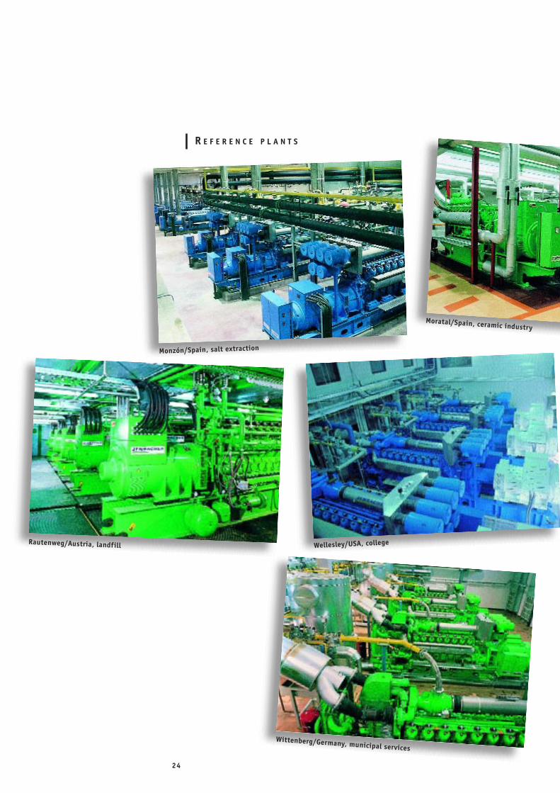
R E F E R E N C E P L A N T S
Monzón/Spain, salt extraction
Moratal/Spain, ceramic industry
Rautenweg/Austria, landfill Wellesley/USA, college
Wittenberg/Germany, municipal services
25
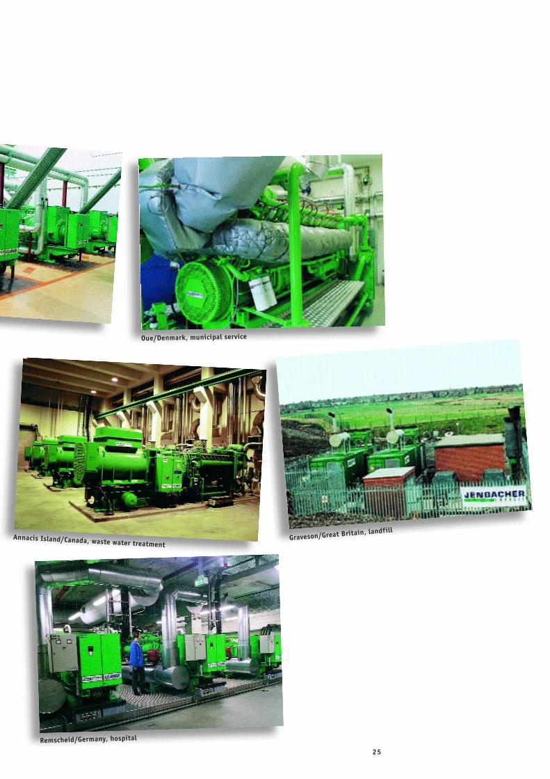
Oue/Denmark, municipal service
Annacis Island/Canada, waste water treatmentGraveson/Great Britain, landfill
Remscheid/Germany, hospital
•• •
• ••
•• •
•
••
•
•••
•
•••
•
•
••
•
••••
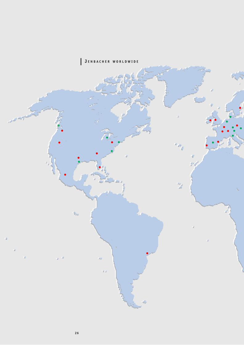
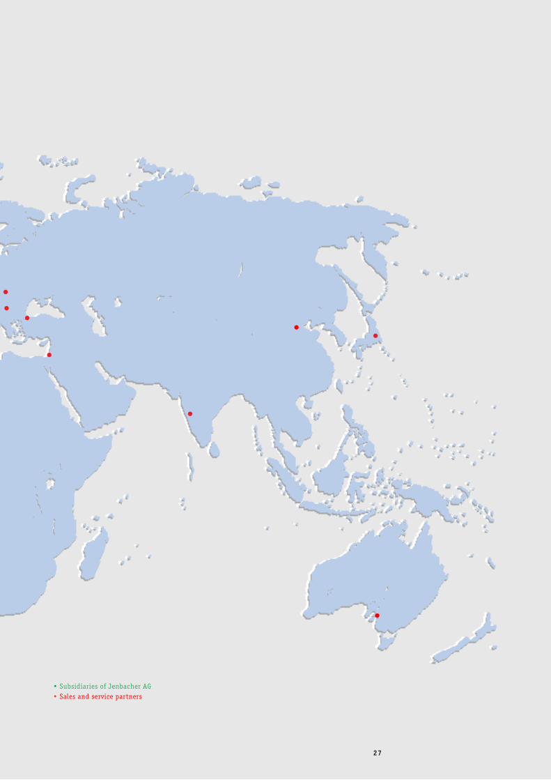
J E N B A C H E R W O R L D W I D E
26
•
••
••
•
• Subsidiaries of Jenbacher AG• Sales and service partners
•
•
27
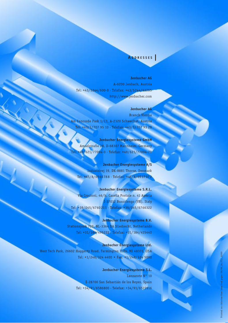
A D D R E S S E S
Prin
ted
on
ch
lori
ne-
free
ble
ach
ed p
aper
09/
99_k
t/FL
L_50
00
Jenbacher AG
A-6200 Jenbach, Austria
Tel: +43/5244/600-0 . Telefax: +43/5244/63255
http://www.jenbacher.com
Jenbacher AG
Branch Vienna
Am Concorde Park 1/C3, A-2320 Schwechat, Austria
Tel: +43/1/707 95 10 . Telefax: +43/1/707 93 28
Jenbacher Energiesysteme GmbH
Amselstraße 28, D-68307 Mannheim, Germany
Tel: +49/621/77094-0 . Telefax: +49/621/77094-70
Jenbacher Energiesysteme A/S
Industrivej 19, DK-8881 Thorsø, Denmark
Tel: +45/8/69 66 78 8 . Telefax: +45/8/69 67 07 2
Jenbacher Energiesysteme S.R.L.
Via Crocioni, 46/h, Casella Postale n. 41 Aperta
I-37012 Bussolengo (VR), Italy
Tel: +39/045/6760 211 . Telefax: +39/045/6766322
Jenbacher Energiesysteme B.V.
Stationspark 709, NL-3364 DA Sliedrecht, Netherlands
Tel: +31/184/495222 . Telefax: +31/184/415440
Jenbacher Energiesysteme Ltd.
West Tech Park, 26602 Haggerty Road, Farmington Hills, MI 48331, USA
Tel: +1/248/324 4400 • Fax: +1/248/324 5000
Jenbacher Energiesysteme S.L.
Lanzarote N° 10
E-28700 San Sebastián de los Reyes, Spain
Tel: +34/91/6586800 . Telefax: +34/91/6522616