jcm ductile couplings - remarkable lighting ductile iron couplings jcm ductile iron couplings employ...
TRANSCRIPT
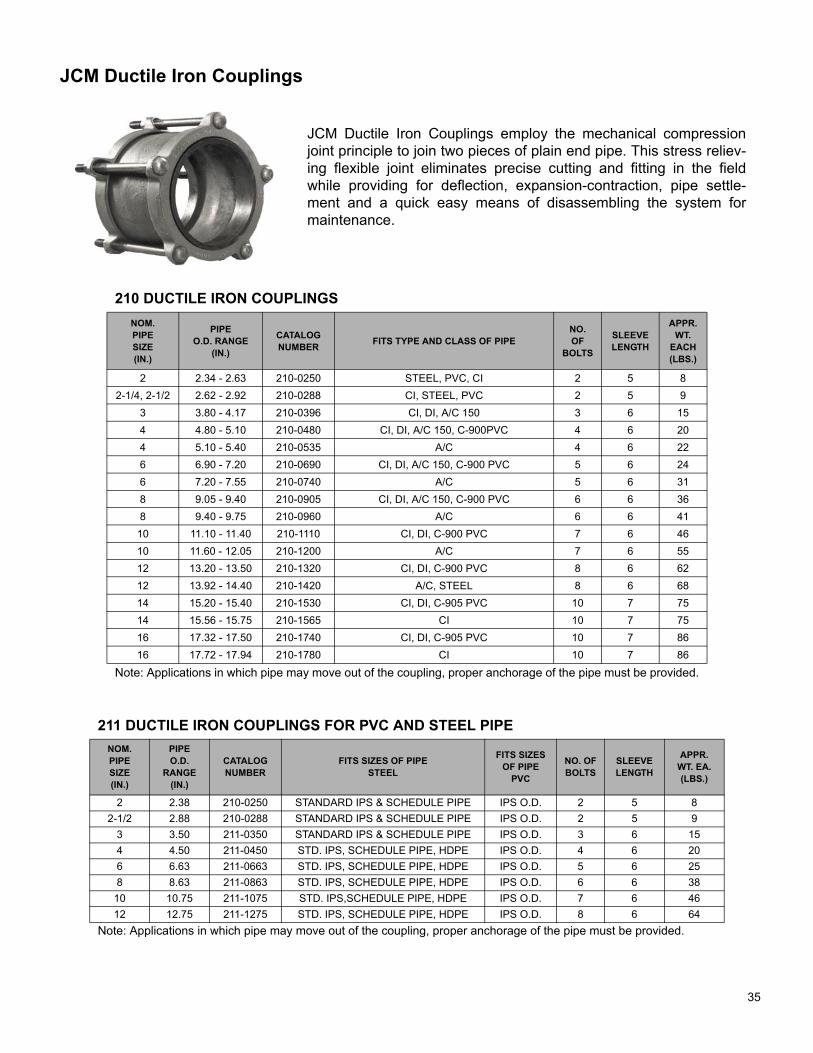
JCM Ductile Iron Couplings
JCM Ductile Iron Couplings employ the mechanical compressionjoint principle to join two pieces of plain end pipe. This stress reliev-ing flexible joint eliminates precise cutting and fitting in the fieldwhile providing for deflection, expansion-contraction, pipe settle-ment and a quick easy means of disassembling the system formaintenance.
210 DUCTILE IRON COUPLINGSNOM.PIPESIZE(IN.)
PIPEO.D. RANGE
(IN.)
CATALOGNUMBER FITS TYPE AND CLASS OF PIPE
NO.OF
BOLTS
SLEEVELENGTH
APPR.WT.
EACH(LBS.)
2 2.34 - 2.63 210-0250 STEEL, PVC, CI 2 5 82-1/4, 2-1/2 2.62 - 2.92 210-0288 CI, STEEL, PVC 2 5 9
3 3.80 - 4.17 210-0396 CI, DI, A/C 150 3 6 154 4.80 - 5.10 210-0480 CI, DI, A/C 150, C-900PVC 4 6 204 5.10 - 5.40 210-0535 A/C 4 6 226 6.90 - 7.20 210-0690 CI, DI, A/C 150, C-900 PVC 5 6 246 7.20 - 7.55 210-0740 A/C 5 6 318 9.05 - 9.40 210-0905 CI, DI, A/C 150, C-900 PVC 6 6 368 9.40 - 9.75 210-0960 A/C 6 6 41
10 11.10 - 11.40 210-1110 CI, DI, C-900 PVC 7 6 4610 11.60 - 12.05 210-1200 A/C 7 6 5512 13.20 - 13.50 210-1320 CI, DI, C-900 PVC 8 6 6212 13.92 - 14.40 210-1420 A/C, STEEL 8 6 6814 15.20 - 15.40 210-1530 CI, DI, C-905 PVC 10 7 7514 15.56 - 15.75 210-1565 CI 10 7 7516 17.32 - 17.50 210-1740 CI, DI, C-905 PVC 10 7 8616 17.72 - 17.94 210-1780 CI 10 7 86
Note: Applications in which pipe may move out of the coupling, proper anchorage of the pipe must be provided.
211 DUCTILE IRON COUPLINGS FOR PVC AND STEEL PIPENOM.PIPESIZE(IN.)
PIPEO.D.
RANGE(IN.)
CATALOGNUMBER
FITS SIZES OF PIPESTEEL
FITS SIZES OF PIPE
PVC
NO. OFBOLTS
SLEEVELENGTH
APPR.WT. EA.(LBS.)
2 2.38 210-0250 STANDARD IPS & SCHEDULE PIPE IPS O.D. 2 5 82-1/2 2.88 210-0288 STANDARD IPS & SCHEDULE PIPE IPS O.D. 2 5 9
3 3.50 211-0350 STANDARD IPS & SCHEDULE PIPE IPS O.D. 3 6 154 4.50 211-0450 STD. IPS, SCHEDULE PIPE, HDPE IPS O.D. 4 6 206 6.63 211-0663 STD. IPS, SCHEDULE PIPE, HDPE IPS O.D. 5 6 258 8.63 211-0863 STD. IPS, SCHEDULE PIPE, HDPE IPS O.D. 6 6 38
10 10.75 211-1075 STD. IPS,SCHEDULE PIPE, HDPE IPS O.D. 7 6 4612 12.75 211-1275 STD. IPS, SCHEDULE PIPE, HDPE IPS O.D. 8 6 64
Note: Applications in which pipe may move out of the coupling, proper anchorage of the pipe must be provided.
35

JCM 212 Ductile Iron Transition Couplings
The JCM 212 Ductile Iron Transition Coupling is part of a uniquely simple coupling system which provides an easymeans of joining plain end pipe. These transition couplings join pipe of the same nominal size that have differentoutside diameter dimensions. At the same time they help overcome common installation problems such as pipemisalignment, stress build up, corrosive environments and working in a limited space.
212 DUCTILE IRON TRANSITION COUPLINGS
NOM.PIPESIZE(IN.)
FROMO.D. RANGE
(IN.)
TRANSITIONTO
O.D. RANGE(IN.)
CATALOG NUMBERNO.OF
BOLTS
SLEEVE LENGTH
APPR.WT.
EACH(LBS.)
2, 2-1/2 2.62 - 2.92 2.38 - 2.50 212-0288-0238 2 5 9
3 3.80 - 4.17 3.50 212-0396-0350 3 6 15
4 4.50 4.00 212-0450-0400 4 6 20
4 4.50 4.22 212-0450-0422 4 6 20
4 4.80 - 5.10 4.00 212-0480-0400 4 6 20
4 4.80 - 5.10 4.22 212-0480-0422 4 6 20
4 4.80 - 5.10 4.50 212-0480-0450 4 6 20
4 5.10 - 5.40 4.50 212-0535-0450 4 6 22
4 5.10 - 5.40 4.80 212-0535-0480 4 6 22
6 6.63 6.00 212-0663-0600 5 6 26
6 6.63 6.30 212-0663-0630 5 6 26
6 6.90 - 7.20 6.00 212-0690-0600 5 6 26
6 6.90 - 7.20 6.30 212-0690-0630 5 6 26
6 6.90 - 7.20 6.63 212-0690-0663 5 6 26
6 7.20 - 7.55 6.63 212-0740-0663 5 6 31
6 7.20 - 7.55 6.90 212-0740-0690 5 6 31
8 8.63 8.00 212-0863-0800 6 6 38
8 8.63 8.40 212-0863-0840 6 6 38
8 9.05 - 9.40 8.00 212-0905-0800 6 6 38
8 9.05 - 9.40 8.40 212-0905-0840 6 6 38
8 9.05 - 9.40 8.63 212-0905-0863 6 6 38
8 9.40 - 9.75 8.63 212-0960-0863 6 6 41
8 9.40 - 9.75 9.05 212-0960-0905 6 6 41
10 10.75 10.50 212-1075-1050 7 6 46
10 11.10 - 11.40 10.50 212-1110-1050 7 6 46
10 11.10 - 11.40 10.75 212-1110-1075 7 6 46
10 11.60 - 12.05 10.75 212-1200-1075 7 6 57
10 11.60 - 12.05 11.10 212-1200-1110 7 6 57
12 12.75 12.50 212-1275-1250 8 6 64
12 13.20 - 13.50 12.50 212-1320-1250 8 6 64
12 13.20 - 13.50 12.75 212-1320-1275 8 6 64
12 13.92 - 14.40 12.75 212-1420-1275 8 6 70
12 13.92 - 14.40 13.20 212-1420-1320 8 6 70
14 15.56 - 15.75 15.20 - 15.40 212-1565-1530 10 7 75
16 17.72 - 17.94 17.32 - 17.50 212-1780-1740 10 7 86
Note: Applications in which pipe may move out of the coupling, proper anchorage of the pipe must be provided.
36
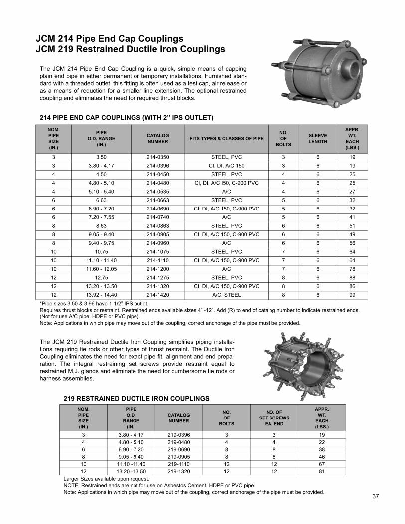
JCM 214 Pipe End Cap CouplingsJCM 219 Restrained Ductile Iron Couplings
The JCM 214 Pipe End Cap Coupling is a quick, simple means of cappingplain end pipe in either permanent or temporary installations. Furnished stan-dard with a threaded outlet, this fitting is often used as a test cap, air release oras a means of reduction for a smaller line extension. The optional restrainedcoupling end eliminates the need for required thrust blocks.
214 PIPE END CAP COUPLINGS (WITH 2” IPS OUTLET)NOM.PIPESIZE(IN.)
PIPE O.D. RANGE
(IN.)
CATALOGNUMBER FITS TYPES & CLASSES OF PIPE
NO.OF
BOLTS
SLEEVELENGTH
APPR.WT.
EACH(LBS.)
3 3.50 214-0350 STEEL, PVC 3 6 193 3.80 - 4.17 214-0396 CI, DI, A/C 150 3 6 194 4.50 214-0450 STEEL, PVC 4 6 254 4.80 - 5.10 214-0480 CI, DI, A/C I50, C-900 PVC 4 6 254 5.10 - 5.40 214-0535 A/C 4 6 276 6.63 214-0663 STEEL, PVC 5 6 326 6.90 - 7.20 214-0690 CI, DI, A/C 150, C-900 PVC 5 6 326 7.20 - 7.55 214-0740 A/C 5 6 418 8.63 214-0863 STEEL, PVC 6 6 518 9.05 - 9.40 214-0905 CI, DI, A/C 150, C-900 PVC 6 6 498 9.40 - 9.75 214-0960 A/C 6 6 56
10 10.75 214-1075 STEEL, PVC 7 6 6410 11.10 - 11.40 214-1110 CI, DI, A/C 150, C-900 PVC 7 6 6410 11.60 - 12.05 214-1200 A/C 7 6 7812 12.75 214-1275 STEEL, PVC 8 6 8812 13.20 - 13.50 214-1320 CI, DI, A/C 150, C-900 PVC 8 6 8612 13.92 - 14.40 214-1420 A/C, STEEL 8 6 99
*Pipe sizes 3.50 & 3.96 have 1-1/2” IPS outlet.Requires thrust blocks or restraint. Restrained ends available sizes 4” -12”. Add (R) to end of catalog number to indicate restrained ends. (Not for use A/C pipe, HDPE or PVC pipe).Note: Applications in which pipe may move out of the coupling, correct anchorage of the pipe must be provided.
The JCM 219 Restrained Ductile Iron Coupling simplifies piping installa-tions requiring tie rods or other types of thrust restraint. The Ductile IronCoupling eliminates the need for exact pipe fit, alignment and end prepa-ration. The integral restraining set screws provide restraint equal torestrained M.J. glands and eliminate the need for cumbersome tie rods orharness assemblies.
219 RESTRAINED DUCTILE IRON COUPLINGSNOM.PIPESIZE(IN.)
PIPEO.D.
RANGE(IN.)
CATALOGNUMBER
NO. OF
BOLTS
NO. OFSET SCREWS
EA. END
APPR.WT.
EACH(LBS.)
3 3.80 - 4.17 219-0396 3 3 194 4.80 - 5.10 219-0480 4 4 226 6.90 - 7.20 219-0690 8 8 388 9.05 - 9.40 219-0905 8 8 46
10 11.10 -11.40 219-1110 12 12 6712 13.20 -13.50 219-1320 12 12 81
Larger Sizes available upon request.NOTE: Restrained ends are not for use on Asbestos Cement, HDPE or PVC pipe.Note: Applications in which pipe may move out of the coupling, correct anchorage of the pipe must be provided.
37

JCM Transition GasketsFor Models 210, 211, 212, 214, 215, 216, 301, 306, 307 Couplings and FCA’s
The uniquely simple JCM Wide Range Coupling and Flanged CouplingAdapter system utilizes self-centering, extra wide transition gaskets eliminatingthe need for stocking special transition couplings or color coded flanges andgaskets. Stock JCM Ductile Iron Coupling and JCM Flanged Coupling Adapt-ers and change only gaskets to make a transition between A/C, Cast Iron, Duc-tile Iron, Steel and PVC pipe. Use the same size gasket on both ends to makea straight coupling.
GASKETS FOR STANDARD SIZE 210 DUCTILE IRON COUPLINGSNOM. PIPE
SIZE(IN.)
FITS COUPLING
SLEEVE
GASKETO.D. RANGE
(IN.)
FITS TYPES & CLASSES OFPIPE
GASKETNUMBER
2-1/4, 2-1/2 210-0288 2.62 - 2.922.38 - 2.50
CI, 2-1/2” PVC, STEEL2” PVC, STEEL, CI
G212-0288G212-0288-0238*
3 210-0396 3.80 - 4.173.50
CI, DI, A/C 150, C-900 PVCIPS PVC, STEEL
G212-0396G212-0396-0350*
4 210-0480
4.74 - 5.104.504.224.00
CI, DI, A/C 150, C-900 PVCIPS PVC, STEEL, HDPE
SDR 35STEEL TUBING
G212-0480G212-0480-0450G212-0480-0422G212-0480-0400
6 210-0690
6.84 -7.266.636.306.00
CI, DI, A/C 150, C-900 PVCIPS PVC, STEEL, HDPE
SDR 35STEEL TUBING
G212-0690G212-0690-0663G212-0690-0630G212-0690-0600
8 210-0905
8.99 - 9.428.638.408.00
CI, DI, A/C 150, C-900 PVCIPS PVC, STEEL, HDPE
SDR 35STEEL TUBING
G212-0905G212-0905-0863G212-0905-0840G212-0905-0800
10 210-111011.04 - 11.40
10.7510.50
CI, DI, C-900 PVCIPS PVC, STEEL, HDPE
SDR 35
G212-1110G212-1110-1075G212-1110-1050
12 210-132013.14 -13.50
12.7512.50
CI, DI, C-900 PVCIPS PVC, STEEL, HDPE
SDR 35
G212-1320G212-1320-1275G212-1320-1250
14 210-1565 15.20 - 15.4015.56 - 15.75
CI, DI, C-905 PVCCI
G212-1530G212-1565
16 210-1780 17.32 - 17.5017.72 - 17.94
CI, DI, C-905 PVCCI
G212-1740G212-1780
*This size gasket does not have extended lip.
GASKETS FOR OVERSIZED 210 DUCTILE IRON COUPLINGSNOM. PIPE
SIZE(IN.)
FITS COUPLING
SLEEVE
GASKET O.D. RANGE
FITS TYPES & CLASSES OF PIPE
GASKET NUMBER
4 210-05355.06 - 5.404.80 - 5.10
4.50
A/CCI, DI, C-900 PVC
IPS PVC, STEEL, HDPE
G212-0535G212-0535-0480G212-0535-0450
6 210-07407.17 - 7.556.90 - 7.10
6.63
A/CCI, DI, C-900 PVC
IPS PVC, STEEL, HDPE
G212-0740G212-0740-0690G212-0740-0663
8 210-09609.32 - 9.759.05 - 9.30
8.63
A/CCI, DI, C-900 PVC
IPS PVC, STEEL, HDPE
G212-0967G212-0967-0905G212-0967-0863
10 210-120011.60 - 12.0511.10 - 11.30
10.75
A/CCI, DI, C-900 PVC
IPS PVC, STEEL, HDPE
G212-1200G212-1200-1110G212-1200-1075
12 210-142013.92 - 14.4013.20 - 13.50
12.75
A/CCI, DI, C-900 PVC
IPS PVC, STEEL, HDPE
G212-1420G212-1420-1320G212-1420-1275
40
JCM Industries, Inc./P. O. Box 1220 / Nash, TX 75569-1220
JCM SBR Gasket Material
Styrene Butadiene Rubber (SBR) has good physical properties. It has excellent abrasion resis-tance and is suitable for application with water, salt solutions, mild acids and bases. It has amaximum operating temperature rating of 180o F. The material is not recommended for use onoil, ozone or weather resistant applications.
The following is a list of JCM products that are furnished with SBR gaskets as standard mate-rial.
210, 211, 212 Ductile Iron Couplings219 Restrained Ductile Iron Coupling301, 306, 307 Flanged Coupling Adapters
JCM SBR Gasket Material used in JCM Fittings is ANSI/NSF Standard 61 Certified with theproduct in which it is supplied. JCM SBR Rubber meets ASTM D-2000 Standard.
JCM SBR GasketMaterial Specifications
JCM Industries, Inc./P. O. Box 1220 / Nash, TX 75569-1220
JCM 210 Ductile Iron Couplings
Couplings for pipe sizes 2" - 16" shall be of ductile iron construction. Couplings shall be of thewide range type to fit Steel, Cast Iron, Ductile Iron, PVC, HDPE and Asbestos-Cement with onlya change of gaskets. Coupling sleeves shall be 5" in length on 2" - 2-1/2" pipe sizes, 6" in lengthon pipe sizes 3" - 12" and 7" in length on pipe sizes 14" and 16". Ductile Iron couplings shall beJCM 210, 211, 212, or approved equal.
JCM 200 Series Ductile Iron Couplings are ANSI/NSF Standard 61 Certified.
JCM 200 Series Ductile Iron Coupling
Nominal Pipe Size Sleeve Length Number of Bolts2 "5 "22-1/2 "5 "23 "6 "34 "6 "46 "6 "58 "6 "610 "6 "712 "6 "814 "7 "1016 "7 "10
Note: For applications with High Density Polyethylene Pipe, refer to the JCM HDPE FittingsManual or contact JCM Industries.
JCM 210 Ductile Iron CouplingTypical Specifications
JCM Industries, Inc./P. O. Box 1220 / Nash, TX 75569-1220
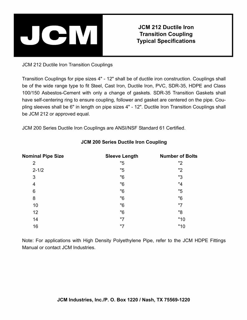
JCM 212 Ductile Iron Transition Couplings
Transition Couplings for pipe sizes 4" - 12" shall be of ductile iron construction. Couplings shallbe of the wide range type to fit Steel, Cast Iron, Ductile Iron, PVC, SDR-35, HDPE and Class100/150 Asbestos-Cement with only a change of gaskets. SDR-35 Transition Gaskets shallhave self-centering ring to ensure coupling, follower and gasket are centered on the pipe. Cou-pling sleeves shall be 6" in length on pipe sizes 4" - 12". Ductile Iron Transition Couplings shallbe JCM 212 or approved equal.
JCM 200 Series Ductile Iron Couplings are ANSI/NSF Standard 61 Certified.
JCM 200 Series Ductile Iron Coupling
Nominal Pipe Size Sleeve Length Number of Bolts2 "5 "22-1/2 "5 "23 "6 "34 "6 "46 "6 "58 "6 "610 "6 "712 "6 "814 "7 "1016 "7 "10
Note: For applications with High Density Polyethylene Pipe, refer to the JCM HDPE FittingsManual or contact JCM Industries.
JCM 212 Ductile IronTransition Coupling
Typical Specifications
JCM Industries, Inc./P. O. Box 1220 / Nash, TX 75569-1220
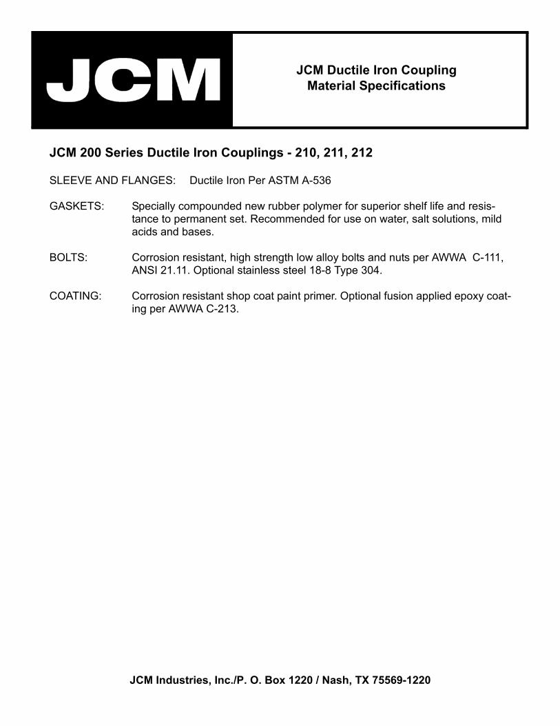
JCM 200 Series Ductile Iron Couplings - 210, 211, 212
SLEEVE AND FLANGES: Ductile Iron Per ASTM A-536
GASKETS: Specially compounded new rubber polymer for superior shelf life and resis-tance to permanent set. Recommended for use on water, salt solutions, mild acids and bases.
BOLTS: Corrosion resistant, high strength low alloy bolts and nuts per AWWA C-111, ANSI 21.11. Optional stainless steel 18-8 Type 304.
COATING: Corrosion resistant shop coat paint primer. Optional fusion applied epoxy coat-ing per AWWA C-213.
JCM Ductile Iron CouplingMaterial Specifications

JCM Industries, Inc./P. O. Box 1220 / Nash, TX 75569-1220
JCM Ductile Iron Couplings are manufactured from ASTM A-536 Ductile Iron and have low alloybolts to ANSI 21.11. These heavy-duty couplings have a heavy gasket, which is recommendedfor water, salt solutions, mild acids and bases.
Pressure ratings on these couplings represent the sealing capability of the product. Note: wherepipe movement out of the coupling might occur, proper anchorage of the pipe must be provided.
CouplingModel Number Nominal Pipe Size Type of Pipe Pressure Rating
210 2" - 12 "Ductile Iron, Cast Iron, A/C 250 PSI211 2" - 12 "Steel, PVC 250 PSI212 2" - 12 "CI, DI, to Steel, PVC 250 PSI212 3" - 8 "A/C to CI, DI 250 PSI212 10"- 12 "A/C to CI, DI 150 PSI212 4" - 12 "Oversized A/C to Steel 150 PSI212 4" - 8 "A/C, CI, DI, to O.D. Steel Pipe 150 PSI
For higher pressure applications, contact JCM Industries.
JCM 210 Ductile Iron Couplings for Cast Iron (CI), Ductile Iron (DI), C-900 PVC and AsbestosCement (A/C)
JCM 211 Ductile Iron Couplings for Steel Pipe and IPS Size PVC
JCM 212 Ductile Iron Transition Couplings to join pipe of different outside diameters.
For applications with High Density Polyethylene Pipe, refer to the JCM HDPE Fittings Manual orcontact JCM Industries.
JCM Ductile CouplingPressure Ratings
Typical Specifications

JCM Industries, Inc. / P. O. Box 1220 / Nash, TX 75569-1220
JCM 200 Series Ductile Iron CouplingsInstallation Instructions
1. Clean pipe surface of all dirt, rust, mud or loose scale from pipe ends. Inspect the pipe endswhere gaskets will contact the pipe for any gouges, grooves, irregularities or imperfections thatwill interfere with the gasket seal. Measure the cleaned pipe diameter to confirm proper size ofcoupling for application. Inspection of the pipe’s integrity for product application is the respon-sibility of the end user. *TIP* Difficult to reach or cramped areas on the backside or undersideof the pipe can be visually checked by using a mirror.
2. Measure back on each pipe end one-half of the middle ring length plus two inches and place areference mark. These marks will be a visual reference point for centering the middle ring overthe joint. *TIP* Couplings perform at optimal effectiveness when centered over joint area.
3. Install follower rings, then gasket onto the pipe ends. NOTE: Flat side of the gasket face meetsthe follower ring, the tapered side inserts into the middle ring. *TIP* To ease installation of thegaskets, pipe should be lubricated with water or soapy-water mixture. Alcohol may be added towater in freezing weather. DO NOT use pipe lubricant or grease based products to lubricate.
4. Install middle ring on one pipe end. Insert other pipe end into middle ring and center the middlering over the joint, between the reference marks.
5. Torque coupling bolts on opposite sides, using a star rotation pattern, drawing up the followersevenly until all bolts have been tightened to a minimum of 75 foot pounds of torque.
NOTES: On joints that do not permit centering of the coupling, the pipe ends must beinserted past the end of the gasket a minimum of one and one-half (1-1/2”) inch.
For applications with deflection or offset pipe ends, the pipe end must be inserted a minimumof one and one-half (1-1/2”) inch past the end of the gasket after the deflection/offset hasoccurred. Do not exceed a recommended 4° of pipe deflection with the coupling withoutinspecting the centering and sealing of the gasket in the middle ring and follower ring. Exces-sive deflection will cause the gasket to improperly seal. Lift the middle ring to insure that thegasket is evenly centered in the ends.
IMPORTANT: Standard couplings do not provide for axial pipe movement. In applications inwhich lateral pipe pull out may occur, pipe restraint must be provided. See fitting manufacturerrecommendations for applications on High Density Polyethylene Pipe.
INT210-0302

JCM Industries, Inc. / P. O. Box 1220 / Nash, TX 75569-1220
JCM 219 RestrainedDuctile Iron Coupling
Installation Instructions
JCM RESTRAINED FITTINGS USING TORQUE HEAD SET SCREWS ARE NOT RECOM-MENDED FOR ASBESTOS CEMENT, PVC, HDPE, FIBERGLASS OR ANY OTHER TYPES OFNON-RIGID OR BRITTLE PIPE MATERIALS. INSPECTION OF PIPE INTEGRITY IS THERESPONSIBILITY OF THE END USER.
1. Clean pipe surface of all dirt, rust, mud or loose scale from pipe ends. Inspect the pipe endswhere gaskets will contact the pipe for any gouges, grooves, irregularities or imperfections thatwill interfere with the gasket seal. Measure the cleaned pipe diameter to confirm proper size ofcoupling for application. Inspection of the pipe’s integrity for product application is the responsi-bility of the end user. *TIP* Difficult to reach or cramped areas on the backside or underside ofthe pipe can be visually checked by using a mirror.
2. Measure back on each pipe end one-half of the middle ring length plus two inches and place areference mark. These marks will be a visual reference point for centering the middle ring overthe joint. *TIP* Couplings perform at optimal effectiveness when centered over joint area.
3. Install follower rings, then gasket onto the pipe ends. NOTE: Flat side of the gasket face meetsthe follower ring, the tapered side inserts into the middle ring. *TIP* To ease installation of thegaskets, pipe should be lubricated with water or soapy-water mixture. Alcohol may be added towater in freezing weather. DO NOT use pipe lubricant or grease based products to lubricate.
4. Install middle ring on one pipe end. Insert other pipe end into middle ring and center the middlering over the joint, between the reference marks. Lift the middle ring to insure that the gasketis evenly centered in the ends.
5. Torque coupling bolts on opposite sides, using a star rotation pattern, drawing up the followersevenly until all bolts have been tightened to 60 to 75 foot pounds of torque.
6. Using a 12 point 7/16” socket wrench, evenly tighten all restraining set screws until they arein contact with the pipe. Then alternately tighten them in a star rotation pattern to approxi-mately 50 foot pounds of torque. To complete installation, tighten all set screws in a star pat-tern until the special break away head shears off. This indicates that the pre-set optimumtorque value of the set screw (80-90ft/lbs) has been reached. The 5/8” square head remain-ing on the set screw is for the convenience of removing the set screw should removal of thefitting be necessary.
SEE NOTES AND IMPORTANT INFORMATION ON REVERSE
INT219-0700
JCM Industries, Inc. / P. O. Box 1220 / Nash, TX 75569-1220
JCM 219 Restrained Ductile Iron CouplingInstallation Instructions
Continued
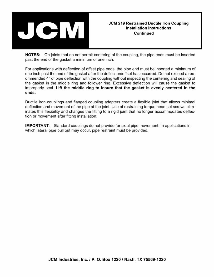
NOTES: On joints that do not permit centering of the coupling, the pipe ends must be insertedpast the end of the gasket a minimum of one inch.
For applications with deflection of offset pipe ends, the pipe end must be inserted a minimum ofone inch past the end of the gasket after the deflection/offset has occurred. Do not exceed a rec-ommended 4° of pipe deflection with the coupling without inspecting the centering and sealing ofthe gasket in the middle ring and follower ring. Excessive deflection will cause the gasket toimproperly seal. Lift the middle ring to insure that the gasket is evenly centered in theends.
Ductile iron couplings and flanged coupling adapters create a flexible joint that allows minimaldeflection and movement of the pipe at the joint. Use of restraining torque head set screws elim-inates this flexibility and changes the fitting to a rigid joint that no longer accommodates deflec-tion or movement after fitting installation.
IMPORTANT: Standard couplings do not provide for axial pipe movement. In applications in which lateral pipe pull out may occur, pipe restraint must be provided.