january 07 - barr- · pdf filesr3 xt43bd sr3 mbu01bd sr2 com01 sr3 packpbd (see page 21) ......
TRANSCRIPT
Zelio® Logic 2Programmable Smart Relays
07Catalog January
This document provided by Barr-Thorp Electric Co., Inc. 800-473-9123 www.barr-thorp.com

0
Modbus®, Telemecanique®, Zelio®, Twido®, and Phaseo® are registered trademarksof Schneider Electric. Other trademarks used herein are the property of their respec-tive owners.
This document provided by Barr-Thorp Electric Co., Inc. 800-473-9123 www.barr-thorp.com
3
Contents 0 Zelio® Logic 2 Programmable Smart Relays 1
Selection guide . . . . . . . . . . . . . . . . . . . . . . . . . . . . . . . . . . . . . . . . . . pages 4 to 7
Compact and modular smart relaysb Presentation . . . . . . . . . . . . . . . . . . . . . . . . . . . . . . . . . . . . . . . . . . pages 8 and 9
b Description. . . . . . . . . . . . . . . . . . . . . . . . . . . . . . . . . . . . . . . . . . . . . . . . . page 10
b Functions . . . . . . . . . . . . . . . . . . . . . . . . . . . . . . . . . . . . . . . . . . . . . .pages 11 to 13
b Characteristics . . . . . . . . . . . . . . . . . . . . . . . . . . . . . . . . . . . . . . . . . . pages 14 to 17
b Curves . . . . . . . . . . . . . . . . . . . . . . . . . . . . . . . . . . . . . . . . . . . . . pages 18 and 19
b References . . . . . . . . . . . . . . . . . . . . . . . . . . . . . . . . . . . . . . . . . . . . . pages 20 to 22
b Dimensions, mounting . . . . . . . . . . . . . . . . . . . . . . . . . . . . . . . . . . . . . . . . . page 23
b Schemes. . . . . . . . . . . . . . . . . . . . . . . . . . . . . . . . . . . . . . . . . . . . . . .pages 24 to 27
Modbus® network slave communication module b Presentation . . . . . . . . . . . . . . . . . . . . . . . . . . . . . . . . . . . . . . . . . . . . . . . . . page 28
b Description, characteristics . . . . . . . . . . . . . . . . . . . . . . . . . . . . . . . . . . . . . page 29
b Functions . . . . . . . . . . . . . . . . . . . . . . . . . . . . . . . . . . . . . . . . . . . . . . . . . . . page 30
b References, dimensions, mounting . . . . . . . . . . . . . . . . . . . . . . . . . . . . . . . page 31
Modem communication interfaceb Presentation, description . . . . . . . . . . . . . . . . . . . . . . . . . . . . . . pages 32 and 33
b Functions . . . . . . . . . . . . . . . . . . . . . . . . . . . . . . . . . . . . . . . . . . . . pages 34 and 35
b Setting-up . . . . . . . . . . . . . . . . . . . . . . . . . . . . . . . . . . . . . . . . . . . . . . . . . page 36
b Characteristics . . . . . . . . . . . . . . . . . . . . . . . . . . . . . . . . . . . . . . . . . . . . . . . page 37
b References . . . . . . . . . . . . . . . . . . . . . . . . . . . . . . . . . . . . . . . . . . . . . . . . . . page 38
b Dimensions . . . . . . . . . . . . . . . . . . . . . . . . . . . . . . . . . . . . . . . . . . . . . . . . . . page 39
b Connections . . . . . . . . . . . . . . . . . . . . . . . . . . . . . . . . . . . . . . . . . . pages 40 and 41
Power suppliesb Presentation . . . . . . . . . . . . . . . . . . . . . . . . . . . . . . . . . . . . . . . . . . . . . . . page 42
b Characteristics, selection. . . . . . . . . . . . . . . . . . . . . . . . . . . . . . . pages 43 and 44
b References, dimensions, mounting . . . . . . . . . . . . . . . . . . . . . . . . . . . . . . . page 45
This document provided by Barr-Thorp Electric Co., Inc. 800-473-9123 www.barr-thorp.com
4
Selection guide 0 Zelio® Logic 2Programmable Smart Relays 0
Compact and modular smart relays
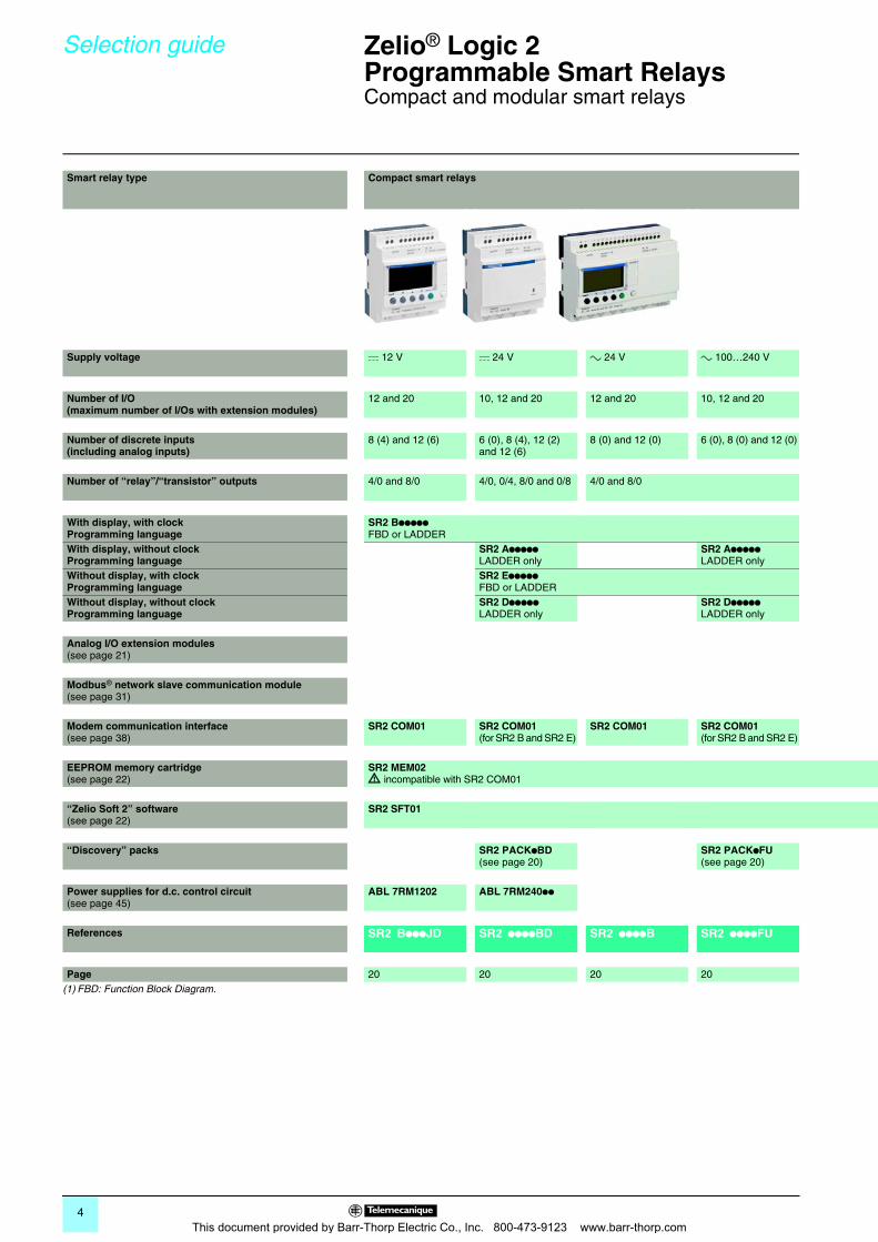
Smart relay type Compact smart relays
Supply voltage c 12 V c 24 V a 24 V a 100…240 V
Number of I/O(maximum number of I/Os with extension modules)
12 and 20 10, 12 and 20 12 and 20 10, 12 and 20
Number of discrete inputs (including analog inputs)
8 (4) and 12 (6) 6 (0), 8 (4), 12 (2) and 12 (6)
8 (0) and 12 (0) 6 (0), 8 (0) and 12 (0)
Number of “relay”/“transistor” outputs 4/0 and 8/0 4/0, 0/4, 8/0 and 0/8 4/0 and 8/0
With display, with clockProgramming language
SR2 BpppppFBD or LADDER
With display, without clockProgramming language
SR2 Appppp LADDER only
SR2 ApppppLADDER only
Without display, with clockProgramming language
SR2 EpppppFBD or LADDER
Without display, without clockProgramming language
SR2 DpppppLADDER only
SR2 DpppppLADDER only
Analog I/O extension modules(see page 21)
Modbus® network slave communication module(see page 31)
Modem communication interface(see page 38)
SR2 COM01 SR2 COM01(for SR2 B and SR2 E)
SR2 COM01 SR2 COM01(for SR2 B and SR2 E)
EEPROM memory cartridge(see page 22)
SR2 MEM02d incompatible with SR2 COM01
“Zelio Soft 2” software(see page 22)
SR2 SFT01
“Discovery” packs SR2 PACKpBD(see page 20)
SR2 PACKpFU(see page 20)
Power supplies for d.c. control circuit(see page 45)
ABL 7RM1202 ABL 7RM240pp
References SR2 BpppJD SR2 ppppBD SR2 ppppB SR2 ppppFU
Page 20 20 20 20(1) FBD: Function Block Diagram.
This document provided by Barr-Thorp Electric Co., Inc. 800-473-9123 www.barr-thorp.com
5
00
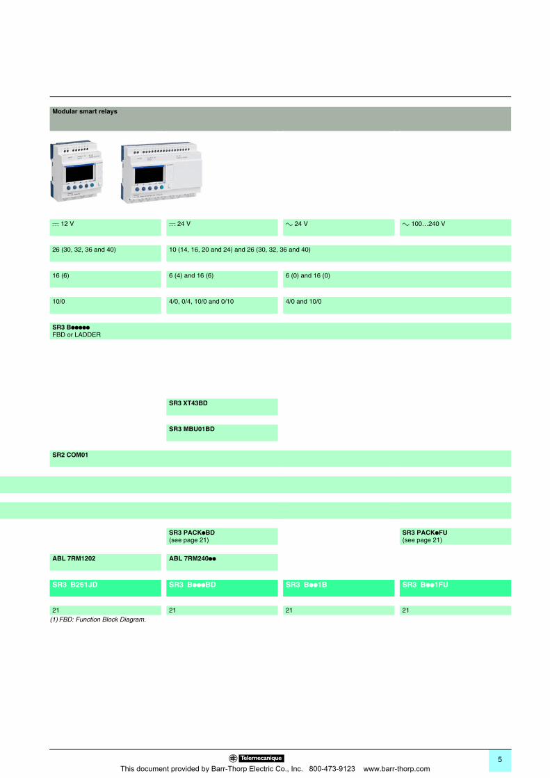
Modular smart relays
c 12 V c 24 V a 24 V a 100…240 V
26 (30, 32, 36 and 40) 10 (14, 16, 20 and 24) and 26 (30, 32, 36 and 40)
16 (6) 6 (4) and 16 (6) 6 (0) and 16 (0)
10/0 4/0, 0/4, 10/0 and 0/10 4/0 and 10/0
SR3 BpppppFBD or LADDER
SR3 XT43BD
SR3 MBU01BD
SR2 COM01
SR3 PACKpBD(see page 21)
SR3 PACKpFU(see page 21)
ABL 7RM1202 ABL 7RM240pp
SR3 B261JD SR3 BpppBD SR3 Bpp1B SR3 Bpp1FU
21 21 21 21(1) FBD: Function Block Diagram.
This document provided by Barr-Thorp Electric Co., Inc. 800-473-9123 www.barr-thorp.com
6
Selection guide 0 Zelio® Logic 2Programmable Smart Relays 0
Extensions and interfaces
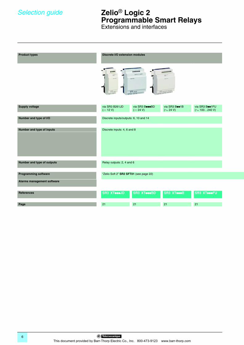
Product types Discrete I/O extension modules
Supply voltage via SR3 B261JD(c 12 V)
via SR3 BpppBD(c 24 V)
via SR3 Bpp1B(a 24 V)
via SR3 Bpp1FU(a 100…240 V)
Number and type of I/O Discrete inputs/outputs: 6, 10 and 14
Number and type of inputs Discrete inputs: 4, 6 and 8
Number and type of outputs Relay outputs: 2, 4 and 6
Programming software “Zelio Soft 2” SR2 SFT01 (see page 22)
Alarms management software
References SR3 XTpppJD SR3 XTpppBD SR3 XTpppB SR3 XTpppFU
Page 21 21 21 21
This document provided by Barr-Thorp Electric Co., Inc. 800-473-9123 www.barr-thorp.com
7
00
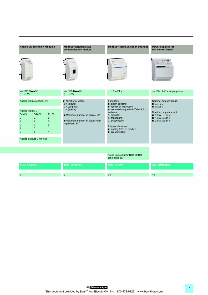
Analog I/O extension modules Modbus® network slave communication module
Modbus® communication interface Power supplies for d.c. control circuit
via SR3 BpppBD(c 24 V)
via SR3 BpppBD(c 24 V)
c 12 to 24 V a 100…240 V single-phase
Analog inputs/outputs: 2/2 b Number of words:v 4 (inputs)v 4 (outputs)v 1 (status)
b Maximum number of slaves: 32
b Maximum number of slaves with repeaters: 247
Functionsb alarm sendingb receipt of instructionb remote dialogue with Zelio Soft 2 software:v Transferv Monitoringv Diagnostics
2 types of modem:b analog (PSTN) modemb GSM modem
Nominal output voltage.:b c 12 Vb c 24 V
Nominal output current:b 1.9 A (c 12 V)b 1.3 A (c 24 V)b 2.5 A (c 24 V)
Analog inputs: 20-10 V 0-20 V Pt1002 0 01 1 00 2 01 0 10 1 1
Analog outputs 0-10 V: 2
“Zelio Logic Alarm” SR2 SFT02 (see page 38)
SR3 XT43BD SR3 MBU01BD SR2 COM01 ABL 7RMppppp
21 31 38 45
This document provided by Barr-Thorp Electric Co., Inc. 800-473-9123 www.barr-thorp.com
8
Presentation 0 Zelio® Logic 2Programmable Smart Relays 0
Compact and modular smart relays
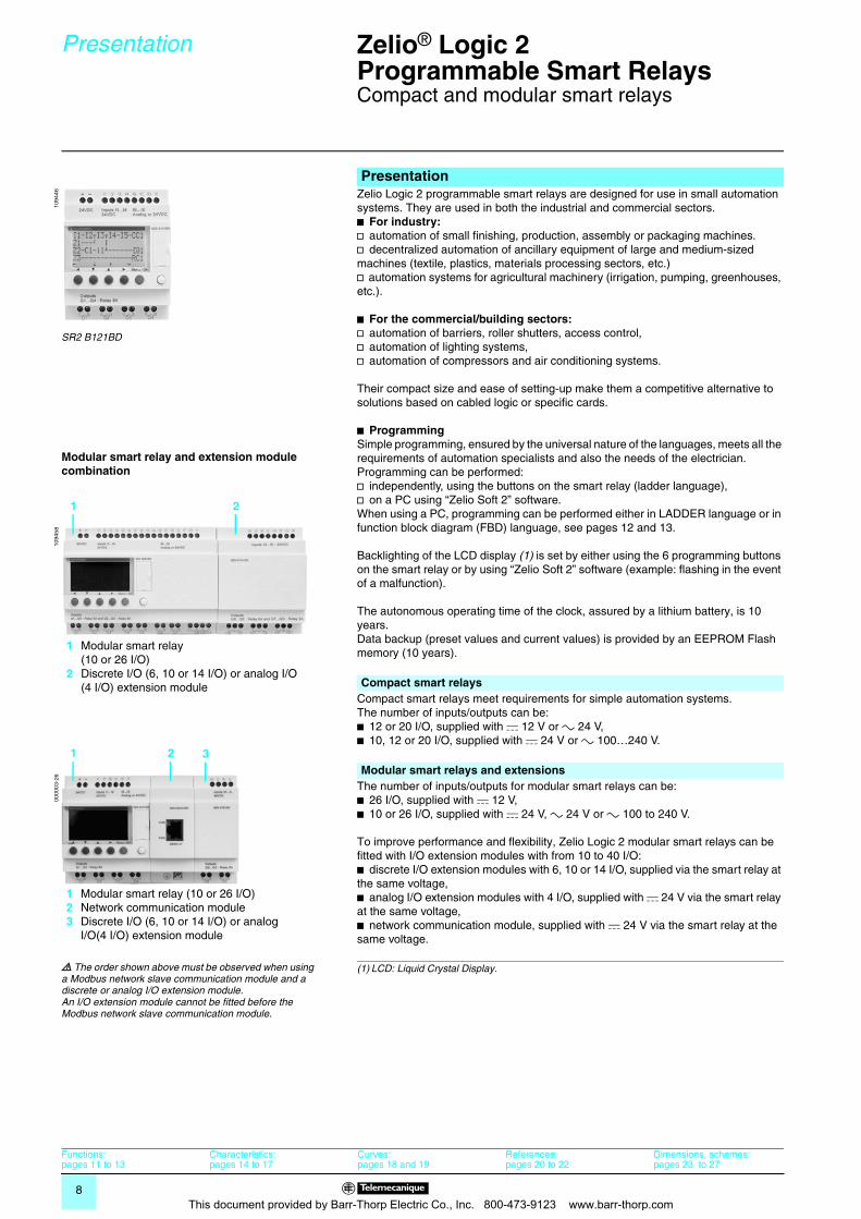
Presentation Zelio Logic 2 programmable smart relays are designed for use in small automation systems. They are used in both the industrial and commercial sectors. b For industry: v automation of small finishing, production, assembly or packaging machines.v decentralized automation of ancillary equipment of large and medium-sized machines (textile, plastics, materials processing sectors, etc.)v automation systems for agricultural machinery (irrigation, pumping, greenhouses, etc.).
b For the commercial/building sectors: v automation of barriers, roller shutters, access control,v automation of lighting systems,v automation of compressors and air conditioning systems.
Their compact size and ease of setting-up make them a competitive alternative to solutions based on cabled logic or specific cards.
b ProgrammingSimple programming, ensured by the universal nature of the languages, meets all the requirements of automation specialists and also the needs of the electrician.Programming can be performed:v independently, using the buttons on the smart relay (ladder language),v on a PC using “Zelio Soft 2” software.When using a PC, programming can be performed either in LADDER language or in function block diagram (FBD) language, see pages 12 and 13.
Backlighting of the LCD display (1) is set by either using the 6 programming buttons on the smart relay or by using “Zelio Soft 2” software (example: flashing in the event of a malfunction).
The autonomous operating time of the clock, assured by a lithium battery, is 10 years.Data backup (preset values and current values) is provided by an EEPROM Flash memory (10 years).
Compact smart relaysCompact smart relays meet requirements for simple automation systems. The number of inputs/outputs can be:b 12 or 20 I/O, supplied with c 12 V or a 24 V,b 10, 12 or 20 I/O, supplied with c 24 V or a 100…240 V.
Modular smart relays and extensionsThe number of inputs/outputs for modular smart relays can be:b 26 I/O, supplied with c 12 V,b 10 or 26 I/O, supplied with c 24 V, a 24 V or a 100 to 240 V.
To improve performance and flexibility, Zelio Logic 2 modular smart relays can be fitted with I/O extension modules with from 10 to 40 I/O:b discrete I/O extension modules with 6, 10 or 14 I/O, supplied via the smart relay at the same voltage,b analog I/O extension modules with 4 I/O, supplied with c 24 V via the smart relay at the same voltage,b network communication module, supplied with c 24 V via the smart relay at the same voltage.
(1) LCD: Liquid Crystal Display.
1094
46
SR2 B121BD
1094
58
1 2
1 Modular smart relay(10 or 26 I/O)
2 Discrete I/O (6, 10 or 14 I/O) or analog I/O (4 I/O) extension module
0000
03-2
6
1 2
1 Modular smart relay (10 or 26 I/O)2 Network communication module3 Discrete I/O (6, 10 or 14 I/O) or analog
I/O(4 I/O) extension module
3
Functions:pages 11 to 13
Characteristics:pages 14 to 17
Curves:pages 18 and 19
References:pages 20 to 22
Dimensions, schemes:pages 23 to 27
Modular smart relay and extension module combination
d The order shown above must be observed when using a Modbus network slave communication module and a discrete or analog I/O extension module.An I/O extension module cannot be fitted before the Modbus network slave communication module.
This document provided by Barr-Thorp Electric Co., Inc. 800-473-9123 www.barr-thorp.com
9
Presentation (continued) 0 Zelio® Logic 2Programmable Smart Relays 0
Compact and modular smart relays
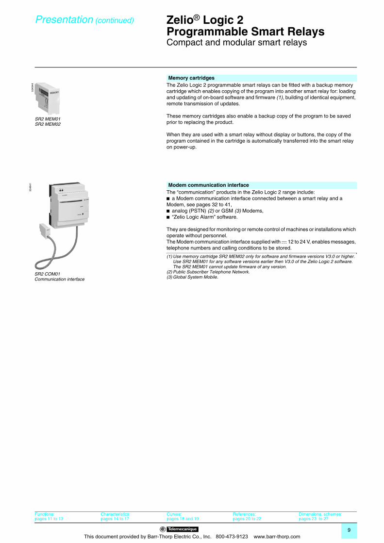
Memory cartridges The Zelio Logic 2 programmable smart relays can be fitted with a backup memory cartridge which enables copying of the program into another smart relay for: loading and updating of on-board software and firmware (1), building of identical equipment, remote transmission of updates.
These memory cartridges also enable a backup copy of the program to be saved prior to replacing the product.
When they are used with a smart relay without display or buttons, the copy of the program contained in the cartridge is automatically transferred into the smart relay on power-up.
Modem communication interface The “communication” products in the Zelio Logic 2 range include:b a Modem communication interface connected between a smart relay and a Modem, see pages 32 to 41, b analog (PSTN) (2) or GSM (3) Modems,b “Zelio Logic Alarm” software.
They are designed for monitoring or remote control of machines or installations which operate without personnel.The Modem communication interface supplied with c 12 to 24 V, enables messages, telephone numbers and calling conditions to be stored.
(1) Use memory cartridge SR2 MEM02 only for software and firmware versions V3.0 or higher. Use SR2 MEM01 for any software versions earlier then V3.0 of the Zelio Logic 2 software. The SR2 MEM01 cannot update firmware of any version.
(2) Public Subscriber Telephone Network.(3) Global System Mobile.
5349
44
SR2 MEM01SR2 MEM02
5349
41
SR2 COM01Communication interface
Functions:pages 11 to 13
Characteristics:pages 14 to 17
Curves:pages 18 and 19
References:pages 20 to 22
Dimensions, schemes:pages 23 to 27
This document provided by Barr-Thorp Electric Co., Inc. 800-473-9123 www.barr-thorp.com
10
Description 0 Zelio® Logic 2Programmable Smart Relays 0
Compact and modular smart relays
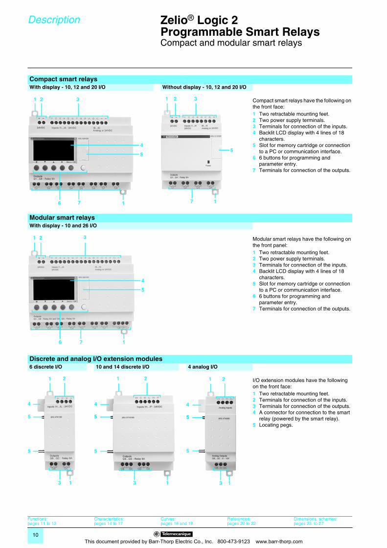
Compact smart relaysWith display - 10, 12 and 20 I/O Without display - 10, 12 and 20 I/O
Compact smart relays have the following on the front face:1 Two retractable mounting feet.2 Two power supply terminals.3 Terminals for connection of the inputs.4 Backlit LCD display with 4 lines of 18
characters.5 Slot for memory cartridge or connection
to a PC or communication interface.6 6 buttons for programming and
parameter entry.7 Terminals for connection of the outputs.
Modular smart relaysWith display - 10 and 26 I/O
Modular smart relays have the following on the front panel:1 Two retractable mounting feet.2 Two power supply terminals.3 Terminals for connection of the inputs.4 Backlit LCD display with 4 lines of 18
characters.5 Slot for memory cartridge or connection
to a PC or communication interface.6 6 buttons for programming and
parameter entry.7 Terminals for connection of the outputs.
Discrete and analog I/O extension modules6 discrete I/O 10 and 14 discrete I/O 4 analog I/O
I/O extension modules have the following on the front face:1 Two retractable mounting feet.2 Terminals for connection of the inputs.3 Terminals for connection of the outputs.4 A connector for connection to the smart
relay (powered by the smart relay).5 Locating pegs.
1 2 3
5
17
4
6
1 2 3
5
17
1 2 3
5
17
4
6
1 2
5
13
5
4
1 2
5
13
55
4
1 2
5
13
55
4
Functions:pages 11 to 13
Characteristics:pages 14 to 17
Curves:pages 18 and 19
References:pages 20 to 22
Dimensions, schemes:pages 23 to 27
This document provided by Barr-Thorp Electric Co., Inc. 800-473-9123 www.barr-thorp.com
11
Functions 0 Zelio® Logic 2Programmable Smart Relays 0
Compact and modular smart relays“Zelio Soft 2” programming software
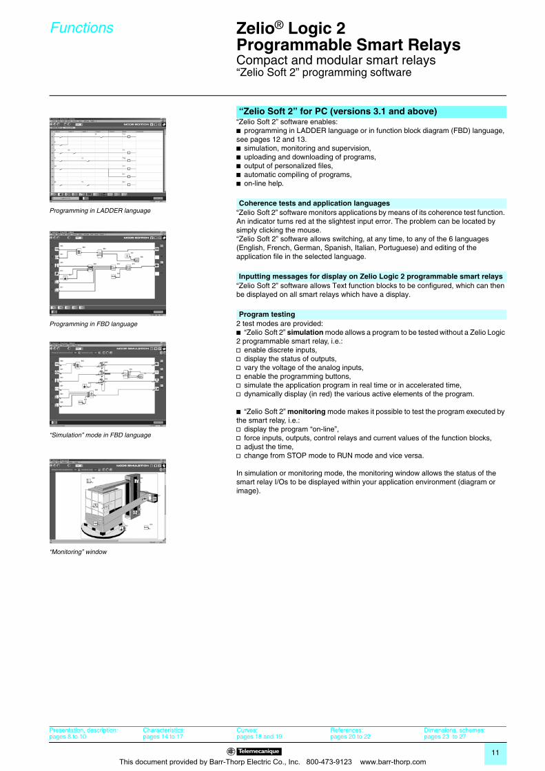
“Zelio Soft 2” software enables:b programming in LADDER language or in function block diagram (FBD) language, see pages 12 and 13.b simulation, monitoring and supervision,b uploading and downloading of programs,b output of personalized files,b automatic compiling of programs,b on-line help.
“Zelio Soft 2” software monitors applications by means of its coherence test function. An indicator turns red at the slightest input error. The problem can be located by simply clicking the mouse. “Zelio Soft 2” software allows switching, at any time, to any of the 6 languages (English, French, German, Spanish, Italian, Portuguese) and editing of the application file in the selected language.
“Zelio Soft 2” software allows Text function blocks to be configured, which can then be displayed on all smart relays which have a display.
2 test modes are provided: b “Zelio Soft 2” simulation mode allows a program to be tested without a Zelio Logic 2 programmable smart relay, i.e.:v enable discrete inputs,v display the status of outputs,v vary the voltage of the analog inputs,v enable the programming buttons,v simulate the application program in real time or in accelerated time,v dynamically display (in red) the various active elements of the program.
b “Zelio Soft 2” monitoring mode makes it possible to test the program executed by the smart relay, i.e.:v display the program “on-line”,v force inputs, outputs, control relays and current values of the function blocks,v adjust the time,v change from STOP mode to RUN mode and vice versa.
In simulation or monitoring mode, the monitoring window allows the status of the smart relay I/Os to be displayed within your application environment (diagram or image).
“Zelio Soft 2” for PC (versions 3.1 and above)
Programming in LADDER languageCoherence tests and application languages
Programming in FBD language
Inputting messages for display on Zelio Logic 2 programmable smart relays
Program testing
“Simulation” mode in FBD language
“Monitoring” window
Presentation, description:pages 8 to 10
Characteristics:pages 14 to 17
Curves:pages 18 and 19
References:pages 20 to 22
Dimensions, schemes:pages 23 to 27
This document provided by Barr-Thorp Electric Co., Inc. 800-473-9123 www.barr-thorp.com
12
Functions (continued) 0 Zelio® Logic 2Programmable Smart Relays 0
Compact and modular smart relays“Zelio Soft 2” programming software
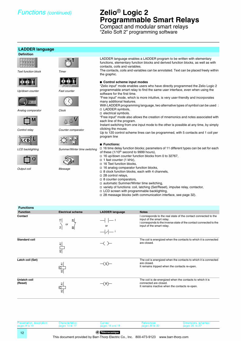
LADDER languageDefinition
Text function block
Up/down counter
Analog comparator
Control relay
LCD backlighting
Output coil
Timer
Fast counter
Clock
Counter comparator
Summer/Winter time switching
Message
LADDER language enables a LADDER program to be written with elementary functions, elementary function blocks and derived function blocks, as well as with contacts, coils and variables.The contacts, coils and variables can be annotated. Text can be placed freely within the graphic.
b Control scheme input modes“Zelio input” mode enables users who have directly programmed the Zelio Logic 2 programmable smart relay to find the same user interface, even when using the software for the first time.“Free input” mode, which is more intuitive, is very user-friendly and incorporates many additional features. With LADDER programming language, two alternative types of symbol can be used : v LADDER symbols,v electrical symbols.“Free input” mode also allows the creation of mnemonics and notes associated with each line of the program.Instant switching from one input mode to the other is possible at any time, by simply clicking the mouse.Up to 120 control scheme lines can be programmed, with 5 contacts and 1 coil per program line
b Functions:v 16 time delay function blocks; parameters of 11 different types can be set for each of these (1/10th second to 9999 hours),v 16 up/down counter function blocks from 0 to 32767,v 1 fast counter (1 kHz),v 16 Text function blocks,v 16 analog comparator function blocks,v 8 clock function blocks, each with 4 channels,v 28 control relays,v 8 counter comparators,v automatic Summer/Winter time switching,v variety of functions: coil, latching (Set/Reset), impulse relay, contactor,v LCD screen with programmable backlighting,v 28 message blocks (with communication interface, see page 32).
FunctionsFunction Electrical scheme LADDER language Notes
Contact I corresponds to the real state of the contact connected to the input of the smart relay.i corresponds to the inverse state of the contact connected to the input of the smart relay.
Standard coil The coil is energized when the contacts to which it is connected are closed.
Latch coil (Set) The coil is energized when the contacts to which it is connected are closed. It remains tripped when the contacts re-open.
Unlatch coil(Reset)
The coil is de-energized when the contacts to which it is connected are closed.It remains inactive when the contacts re-open.
1314 22
21
or or
I
i
A1
A2
A1
A2
S
A1
A2
R
Presentation, description:pages 8 to 10
Characteristics:pages 14 to 17
Curves:pages 18 and 19
References:pages 20 to 22
Dimensions, schemes:pages 23 to 27
This document provided by Barr-Thorp Electric Co., Inc. 800-473-9123 www.barr-thorp.com
13
Functions (continued) 0 Zelio® Logic 2Programmable Smart Relays 0
Compact and modular smart relays“Zelio Soft 2” programming software
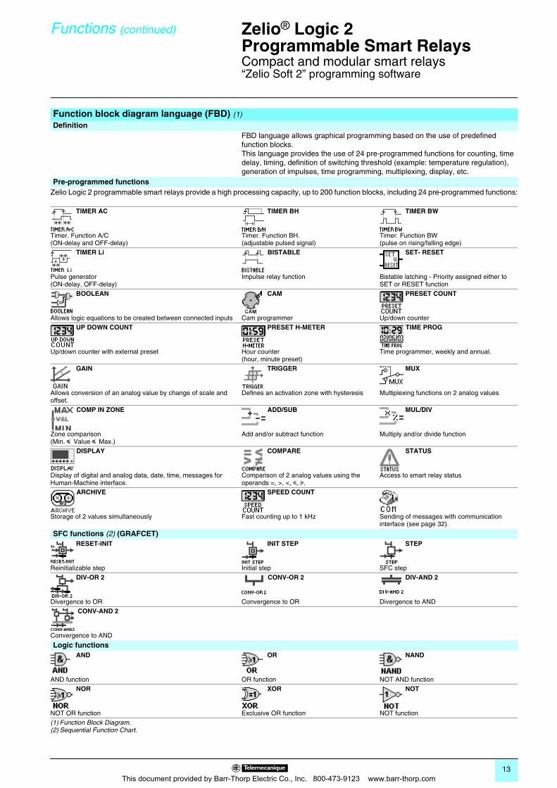
Function block diagram language (FBD) (1)
DefinitionFBD language allows graphical programming based on the use of predefined function blocks. This language provides the use of 24 pre-programmed functions for counting, time delay, timing, definition of switching threshold (example: temperature regulation), generation of impulses, time programming, multiplexing, display, etc.
Pre-programmed functionsZelio Logic 2 programmable smart relays provide a high processing capacity, up to 200 function blocks, including 24 pre-programmed functions:
TIMER AC TIMER BH TIMER BW
Timer. Function A/C(ON-delay and OFF-delay)
Timer. Function BH.(adjustable pulsed signal)
Timer. Function BW(pulse on rising/falling edge)
TIMER Li BISTABLE SET- RESET
Pulse generator(ON-delay, OFF-delay)
Impulse relay function Bistable latching - Priority assigned either to SET or RESET function
BOOLEAN CAM PRESET COUNT
Allows logic equations to be created between connected inputs Cam programmer Up/down counter UP DOWN COUNT PRESET H-METER TIME PROG
Up/down counter with external preset Hour counter(hour, minute preset)
Time programmer, weekly and annual.
GAIN TRIGGER MUX
Allows conversion of an analog value by change of scale and offset.
Defines an activation zone with hysteresis Multiplexing functions on 2 analog values
COMP IN ZONE ADD/SUB MUL/DIV
Zone comparison(Min. y Value y Max.)
Add and/or subtract function Multiply and/or divide function
DISPLAY COMPARE STATUS
Display of digital and analog data, date, time, messages for Human-Machine interface.
Comparison of 2 analog values using the operands =, >, <, y, u.
Access to smart relay status
ARCHIVE SPEED COUNT
Storage of 2 values simultaneously Fast counting up to 1 kHz Sending of messages with communication interface (see page 32).
SFC functions (2) (GRAFCET) RESET-INIT INIT STEP STEP
Reinitializable step Initial step SFC step DIV-OR 2 CONV-OR 2 DIV-AND 2
Divergence to OR Convergence to OR Divergence to AND CONV-AND 2
Convergence to AND
Logic functions AND OR NAND
AND function OR function NOT AND function NOR XOR NOT
NOT OR function Exclusive OR function NOT function(1) Function Block Diagram.(2) Sequential Function Chart.
This document provided by Barr-Thorp Electric Co., Inc. 800-473-9123 www.barr-thorp.com
14
Characteristics 0 Zelio® Logic 2Programmable Smart Relays 0
Compact and modular smart relays
(1) Except for the configuration SR3 BpppBD + SR3 MBU01BD + SR3 XT43BD class A (class B: work in progress).
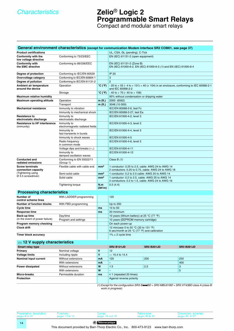
General environment characteristics (except for communication Modem interface SR2 COM01, see page 37)Product certifications UL, CSA, GL (pending), C-TickConformity with thelow voltage directive
Conforming to 73/23/EEC EN (IEC) 61131-2 (open equipment)
Conformity with the EMC directive
Conforming to 89/336/EEC EN (IEC) 61131-2 (Zone B)EN (IEC) 61000-6-2, EN (IEC) 61000-6-3 (1) and EN (IEC) 61000-6-4
Degree of protection Conforming to IEC/EN 60529 IP 20Overvoltage category Conforming to IEC/EN 60664-1 3Degree of pollution Conforming to IEC/EN 61131-2 2Ambient air temperaturearound the device
Operation °C (°F) - 20 to + 55 (- 4 to + 131) + 40 (+ 104) in an enclosure, conforming to IEC 60068-2-1 and IEC 60068-2-2
Storage °C (°F) - 40 to + 70 (- 40 to + 158)Maximum relative humidity 95% without condensation or dripping waterMaximum operating altitude Operation m (ft.) 2000 (6562)
Transport m (ft.) 3048 (10 000)Mechanical resistance Immunity to vibration IEC/EN 60068-2-6, test Fc
Immunity to mechanical shock IEC/EN 60068-2-27, test EaResistance to electrostatic discharge
Immunity to electrostatic discharge
IEC/EN 61000-4-2, level 3
Resistance to HF interference(immunity)
Immunity to electromagnetic radiated fields
IEC/EN 61000-4-3, level 3
Immunity to fast transients in bursts
IEC/EN 61000-4-4, level 3
Immunity to shock waves IEC/EN 61000-4-5Radio frequency in common mode
IEC/EN 61000-4-6, level 3
Voltage dips and breaks (a) IEC/EN 61000-4-11Immunity to damped oscillation waves
IEC/EN 61000-4-12
Conducted and radiated emissions
Conforming to EN 55022/11 (Group 1)
Class B (1)
Screw terminals connection capacity(Tightening using Ø 3.5 screwdriver)
Flexible cable with cable end mm2 1 conductor: 0.25 to 2.5, cable: AWG 24 to AWG 142 conductors: 0.25 to 0.75, cable: AWG 24 to AWG 18
Semi-solid cable mm2 1 conductor: 0.2 to 2.5 cable: AWG 25 to AWG 14Solid cable mm2 1 conductor: 0.2 to 2.5, cable: AWG 25 to AWG 14
2 conductors: 0.2 to 1.5, cable: AWG 24 to AWG 16Tightening torque N.m
(lbf-in)0.5 (4.4)
Processing characteristicsNumber of control scheme lines
With LADDER programming 120
Number of function blocks With FBD programming Up to 200Cycle time ms 10 to 50Response time ms 20 minimumBack-up time(in the event of power failure)
Day/time 10 years (lithium battery) at 25 °C (77 °F)Program and settings 10 years (EEPROM memory cartridge)
Program memory checking On each power-upClock drift 12 min/year 0 to 55 °C (32 to 131 °F)
6 sec/month at 25 °C (77 °F) and calibrationTimer block accuracy 1% ± 2 cycle time
c 12 V supply characteristicsSmart relay type SR2 B121JD SR2 B201JD SR3 B261JD
Primary Nominal voltage V 12Voltage limits Including ripple V c 10.4 to 14.4Nominal input current Without extensions mA 120 200 250
With extensions mA – 400Power dissipated Without extensions W 1.5 2.5 3
With extensions W – 5Micro-breaks Permissible duration ms y 1 (repeated 20 times)Protection Against reverse polarity
Presentation, description:pages 8 to 10
Functions:pages 11 to 13
Curves:pages 18 and 19
References:pages 20 to 22
Dimensions, schemes:pages 23 to 27
This document provided by Barr-Thorp Electric Co., Inc. 800-473-9123 www.barr-thorp.com
15
Characteristics (continued) 0 Zelio® Logic 2Programmable Smart Relays 0
Compact and modular smart relays
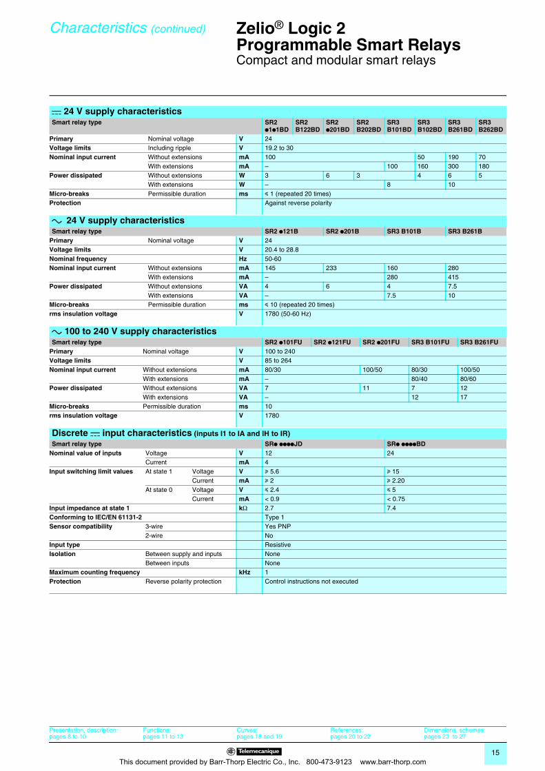
c 24 V supply characteristicsSmart relay type SR2
p1p1BDSR2B122BD
SR2p201BD
SR2B202BD
SR3B101BD
SR3B102BD
SR3B261BD
SR3B262BD
Primary Nominal voltage V 24Voltage limits Including ripple V 19.2 to 30Nominal input current Without extensions mA 100 50 190 70
With extensions mA – 100 160 300 180Power dissipated Without extensions W 3 6 3 4 6 5
With extensions W – 8 10Micro-breaks Permissible duration ms y 1 (repeated 20 times)Protection Against reverse polarity
a 24 V supply characteristicsSmart relay type SR2 p121B SR2 p201B SR3 B101B SR3 B261B
Primary Nominal voltage V 24Voltage limits V 20.4 to 28.8Nominal frequency Hz 50-60Nominal input current Without extensions mA 145 233 160 280
With extensions mA – 280 415Power dissipated Without extensions VA 4 6 4 7.5
With extensions VA – 7.5 10Micro-breaks Permissible duration ms y 10 (repeated 20 times)rms insulation voltage V 1780 (50-60 Hz)
a 100 to 240 V supply characteristicsSmart relay type SR2 p101FU SR2 p121FU SR2 p201FU SR3 B101FU SR3 B261FU
Primary Nominal voltage V 100 to 240Voltage limits V 85 to 264Nominal input current Without extensions mA 80/30 100/50 80/30 100/50
With extensions mA – 80/40 80/60Power dissipated Without extensions VA 7 11 7 12
With extensions VA – 12 17Micro-breaks Permissible duration ms 10rms insulation voltage V 1780
Discrete c input characteristics (inputs I1 to IA and IH to IR)Smart relay type SRp ppppJD SRp ppppBD
Nominal value of inputs Voltage V 12 24Current mA 4
Input switching limit values At state 1 Voltage V u 5.6 u 15Current mA u 2 u 2.20
At state 0 Voltage V y 2.4 y 5Current mA < 0.9 < 0.75
Input impedance at state 1 kΩ 2.7 7.4Conforming to IEC/EN 61131-2 Type 1Sensor compatibility 3-wire Yes PNP
2-wire NoInput type ResistiveIsolation Between supply and inputs None
Between inputs NoneMaximum counting frequency kHz 1Protection Reverse polarity protection Control instructions not executed
Presentation, description:pages 8 to 10
Functions:pages 11 to 13
Curves:pages 18 and 19
References:pages 20 to 22
Dimensions, schemes:pages 23 to 27
This document provided by Barr-Thorp Electric Co., Inc. 800-473-9123 www.barr-thorp.com
16
Characteristics (continued) 0 Zelio® Logic 2Programmable Smart Relays 0
Compact and modular smart relays
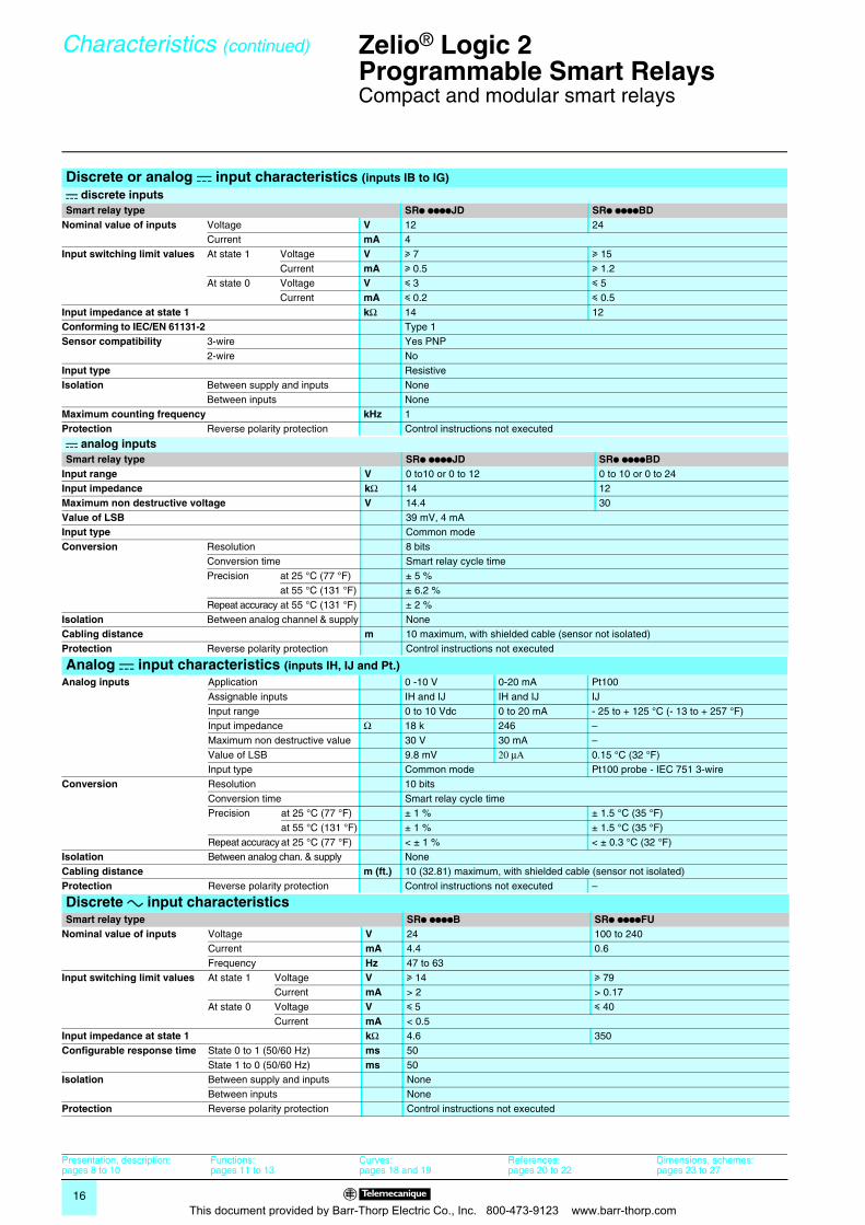
Discrete or analog c input characteristics (inputs IB to IG)c discrete inputsSmart relay type SRp ppppJD SRp ppppBD
Nominal value of inputs Voltage V 12 24Current mA 4
Input switching limit values At state 1 Voltage V u 7 u 15Current mA u 0.5 u 1.2
At state 0 Voltage V y 3 y 5Current mA y 0.2 y 0.5
Input impedance at state 1 kΩ 14 12Conforming to IEC/EN 61131-2 Type 1Sensor compatibility 3-wire Yes PNP
2-wire NoInput type ResistiveIsolation Between supply and inputs None
Between inputs NoneMaximum counting frequency kHz 1Protection Reverse polarity protection Control instructions not executed
c analog inputsSmart relay type SRp ppppJD SRp ppppBD
Input range V 0 to10 or 0 to 12 0 to 10 or 0 to 24Input impedance kΩ 14 12Maximum non destructive voltage V 14.4 30Value of LSB 39 mV, 4 mAInput type Common modeConversion Resolution 8 bits
Conversion time Smart relay cycle timePrecision at 25 °C (77 °F) ± 5 %
at 55 °C (131 °F) ± 6.2 %Repeat accuracy at 55 °C (131 °F) ± 2 %
Isolation Between analog channel & supply NoneCabling distance m 10 maximum, with shielded cable (sensor not isolated)Protection Reverse polarity protection Control instructions not executed
Analog c input characteristics (inputs IH, IJ and Pt.)Analog inputs Application 0 -10 V 0-20 mA Pt100
Assignable inputs IH and IJ IH and IJ IJInput range 0 to 10 Vdc 0 to 20 mA - 25 to + 125 °C (- 13 to + 257 °F)Input impedance Ω 18 k 246 –Maximum non destructive value 30 V 30 mA –Value of LSB 9.8 mV 20 μΑ 0.15 °C (32 °F)Input type Common mode Pt100 probe - IEC 751 3-wire
Conversion Resolution 10 bitsConversion time Smart relay cycle timePrecision at 25 °C (77 °F) ± 1 % ± 1.5 °C (35 °F)
at 55 °C (131 °F) ± 1 % ± 1.5 °C (35 °F)Repeat accuracy at 25 °C (77 °F) < ± 1 % < ± 0.3 °C (32 °F)
Isolation Between analog chan. & supply NoneCabling distance m (ft.) 10 (32.81) maximum, with shielded cable (sensor not isolated)Protection Reverse polarity protection Control instructions not executed –
Discrete a input characteristicsSmart relay type SRp ppppB SRp ppppFU
Nominal value of inputs Voltage V 24 100 to 240Current mA 4.4 0.6Frequency Hz 47 to 63
Input switching limit values At state 1 Voltage V u 14 u 79Current mA > 2 > 0.17
At state 0 Voltage V y 5 y 40Current mA < 0.5
Input impedance at state 1 kΩ 4.6 350Configurable response time State 0 to 1 (50/60 Hz) ms 50
State 1 to 0 (50/60 Hz) ms 50Isolation Between supply and inputs None
Between inputs NoneProtection Reverse polarity protection Control instructions not executed
Presentation, description:pages 8 to 10
Functions:pages 11 to 13
Curves:pages 18 and 19
References:pages 20 to 22
Dimensions, schemes:pages 23 to 27
This document provided by Barr-Thorp Electric Co., Inc. 800-473-9123 www.barr-thorp.com
17
Characteristics (continued) 0 Zelio® Logic 2Programmable Smart Relays 0
Compact and modular smart relays
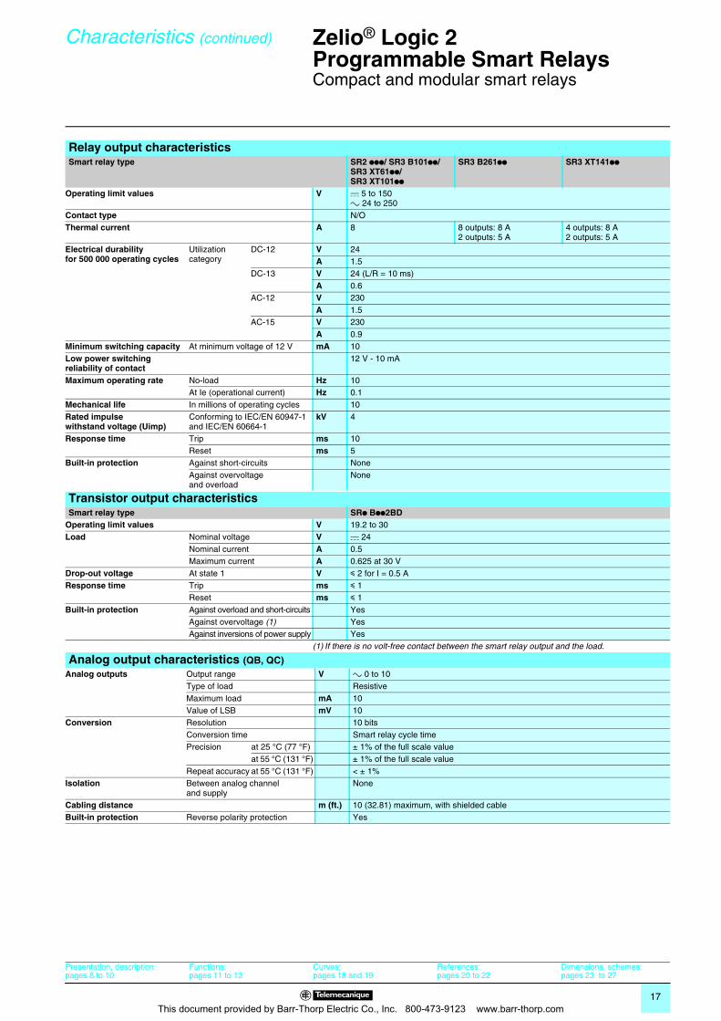
Relay output characteristicsSmart relay type SR2 ppp/ SR3 B101pp/
SR3 XT61pp/ SR3 XT101pp
SR3 B261pp SR3 XT141pp
Operating limit values V c 5 to 150 a 24 to 250
Contact type N/OThermal current A 8 8 outputs: 8 A
2 outputs: 5 A4 outputs: 8 A2 outputs: 5 A
Electrical durabilityfor 500 000 operating cycles
Utilization category
DC-12 V 24A 1.5
DC-13 V 24 (L/R = 10 ms)A 0.6
AC-12 V 230A 1.5
AC-15 V 230A 0.9
Minimum switching capacity At minimum voltage of 12 V mA 10Low power switching reliability of contact
12 V - 10 mA
Maximum operating rate No-load Hz 10At Ie (operational current) Hz 0.1
Mechanical life In millions of operating cycles 10Rated impulse withstand voltage (Uimp)
Conforming to IEC/EN 60947-1 and IEC/EN 60664-1
kV 4
Response time Trip ms 10Reset ms 5
Built-in protection Against short-circuits NoneAgainst overvoltage and overload
None
Transistor output characteristicsSmart relay type SRp Bpp2BD
Operating limit values V 19.2 to 30Load Nominal voltage V c 24
Nominal current A 0.5Maximum current A 0.625 at 30 V
Drop-out voltage At state 1 V y 2 for I = 0.5 AResponse time Trip ms y 1
Reset ms y 1Built-in protection Against overload and short-circuits Yes
Against overvoltage (1) YesAgainst inversions of power supply Yes
(1) If there is no volt-free contact between the smart relay output and the load.
Analog output characteristics (QB, QC)Analog outputs Output range V a 0 to 10
Type of load ResistiveMaximum load mA 10Value of LSB mV 10
Conversion Resolution 10 bitsConversion time Smart relay cycle timePrecision at 25 °C (77 °F) ± 1% of the full scale value
at 55 °C (131 °F) ± 1% of the full scale valueRepeat accuracy at 55 °C (131 °F) < ± 1%
Isolation Between analog channel and supply
None
Cabling distance m (ft.) 10 (32.81) maximum, with shielded cableBuilt-in protection Reverse polarity protection Yes
Presentation, description:pages 8 to 10
Functions:pages 11 to 13
Curves:pages 18 and 19
References:pages 20 to 22
Dimensions, schemes:pages 23 to 27
This document provided by Barr-Thorp Electric Co., Inc. 800-473-9123 www.barr-thorp.com
18
Curves 0 Zelio® Logic 2Programmable Smart Relays 0
Compact and modular smart relays
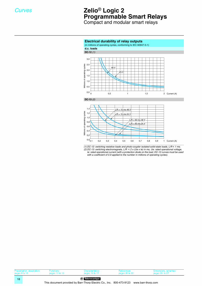
Electrical durability of relay outputs(in millions of operating cycles, conforming to IEC 60947-5-1)
d.c. loadsDC-12 (1)
DC-13 (2)
(1) DC-12: switching resistive loads and photo-coupler isolated solid-state loads, L/R y 1 ms.(2) DC-13: switching electromagnets, L/R y 2 x (Ue x Ie) in ms, Ue: rated operational voltage,
Ie: rated operational current (with a protection diode on the load, DC-12 curves must be used with a coefficient of 0.9 applied to the number in millions of operating cycles).
0 1,51 20,50,0
0,5
1,0
1,5
2,0
2,5
3,0
24 V
48 V
Mill
ions
of o
pera
ting
cycl
es
Current (A)
0,1 0,3 0,5 0,7 0,9 10,2 0,4 0,6 0,80,0
1,4
1,2
1,0
0,8
0,6
0,4
0,2
L/R = 10 ms 24 V
L/R = 10 ms 48 V
L/R = 60 ms 48 V
L/R = 60 ms 24 V
Mill
ions
of o
pera
ting
cycl
es
Current (A)
Presentation, description:pages 8 to 10
Functions:pages 11 to 13
Characteristics:pages 14 to 17
References:pages 20 to 22
Dimensions, schemes:pages 23 to 27
This document provided by Barr-Thorp Electric Co., Inc. 800-473-9123 www.barr-thorp.com
19
Curves (continued) 0 Zelio® Logic 2Programmable Smart Relays 0
Compact and modular smart relays
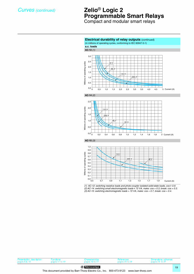
Electrical durability of relay outputs (continued)(in millions of operating cycles, conforming to IEC 60947-5-1)
a.c. loadsAC-12 (1)
AC-14 (2)
AC-15 (3)
(1) AC-12: switching resistive loads and photo-coupler isolated solid-state loads, cos u 0.9.(2) AC-14: switching small electromagnetic loads y 72 VA, make: cos = 0.3, break: cos = 0.3.(3) AC-15: switching electromagnetic loads > 72 VA, make: cos = 0.7, break: cos = 0.4.
0 0,5 1,5 2,5 3,5 4,51,0 2,0 3,0 4,0 50,0
0,5
1,0
1,5
2,0
2,5
3,0
24 V
48 V
110 V
230 V
Mill
ions
of o
pera
ting
cycl
es
Current (A)
0 0,2 0,6 1,0 1,4 1,80,4 0,8 1,2 1,6 20,0
0,5
1,0
1,5
2,0
2,5
24 V48 V
110 V
230 V
Mill
ions
of o
pera
ting
cycl
es
Current (A)
0,5 0,90,7 1,31,1 1,71,5 1,90,0
0,1
0,2
0,3
0,4
0,5
0,6
0,7
0,8
0,9
1,0
230 V 48 V
110 V
Mill
ions
of o
pera
ting
cycl
es
Current (A)
Presentation, description:pages 8 to 10
Functions:pages 11 to 13
Characteristics:pages 14 to 17
References:pages 20 to 22
Dimensions, schemes:pages 23 to 27
This document provided by Barr-Thorp Electric Co., Inc. 800-473-9123 www.barr-thorp.com
20
References 0 Zelio® Logic 2Programmable Smart Relays 0
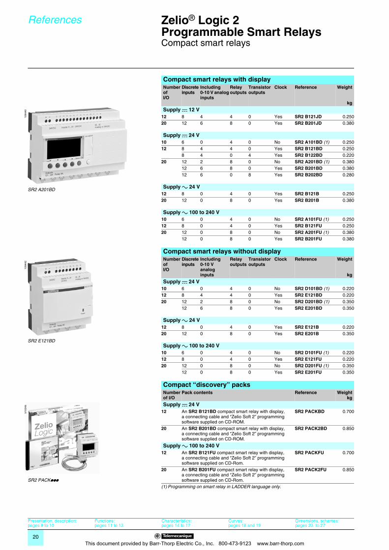
Compact smart relays
Compact smart relays with displayNumber ofI/O
Discrete inputs
Including 0-10 V analog inputs
Relay outputs
Transistor outputs
Clock Reference Weight
kg
Supply c 12 V12 8 4 4 0 Yes SR2 B121JD 0.25020 12 6 8 0 Yes SR2 B201JD 0.380
Supply c 24 V10 6 0 4 0 No SR2 A101BD (1) 0.25012 8 4 4 0 Yes SR2 B121BD 0.250
8 4 0 4 Yes SR2 B122BD 0.22020 12 2 8 0 No SR2 A201BD (1) 0.380
12 6 8 0 Yes SR2 B201BD 0.38012 6 0 8 Yes SR2 B202BD 0.280
Supply a 24 V12 8 0 4 0 Yes SR2 B121B 0.25020 12 0 8 0 Yes SR2 B201B 0.380
Supply a 100 to 240 V10 6 0 4 0 No SR2 A101FU (1) 0.25012 8 0 4 0 Yes SR2 B121FU 0.25020 12 0 8 0 No SR2 A201FU (1) 0.380
12 0 8 0 Yes SR2 B201FU 0.380
Compact smart relays without displayNumber ofI/O
Discrete inputs
Including0-10 V analog inputs
Relay outputs
Transistor outputs
Clock Reference Weight
kg
Supply c 24 V10 6 0 4 0 No SR2 D101BD (1) 0.22012 8 4 4 0 Yes SR2 E121BD 0.22020 12 2 8 0 No SR2 D201BD (1) 0.350
12 6 8 0 Yes SR2 E201BD 0.350
Supply a 24 V12 8 0 4 0 Yes SR2 E121B 0.22020 12 0 8 0 Yes SR2 E201B 0.350
Supply a 100 to 240 V10 6 0 4 0 No SR2 D101FU (1) 0.22012 8 0 4 0 Yes SR2 E121FU 0.22020 12 0 8 0 No SR2 D201FU (1) 0.350
12 0 8 0 Yes SR2 E201FU 0.350
Compact “discovery” packsNumber of I/O
Pack contents Reference Weightkg
Supply c 24 V12 An SR2 B121BD compact smart relay with display,
a connecting cable and “Zelio Soft 2” programming software supplied on CD-ROM.
SR2 PACKBD 0.700
20 An SR2 B201BD compact smart relay with display, a connecting cable and “Zelio Soft 2” programming software supplied on CD-ROM.
SR2 PACK2BD 0.850
Supply a 100 to 240 V12 An SR2 B121FU compact smart relay with display,
a connecting cable and “Zelio Soft 2” programming software supplied on CD-Rom.
SR2 PACKFU 0.700
20 An SR2 B201FU compact smart relay with display, a connecting cable and “Zelio Soft 2” programming software supplied on CD-Rom.
SR2 PACK2FU 0.850
(1) Programming on smart relay in LADDER language only.
1094
40
SR2 A201BD
1094
42
SR2 E121BD
5103
45
SR2 PACKppp
Presentation, description:pages 8 to 10
Functions:pages 11 to 13
Characteristics:pages 14 to 17
Curves:pages 18 and 19
Dimensions, schemes:pages 23 to 27
This document provided by Barr-Thorp Electric Co., Inc. 800-473-9123 www.barr-thorp.com
21
References 0 Zelio® Logic 2Programmable Smart Relays 0
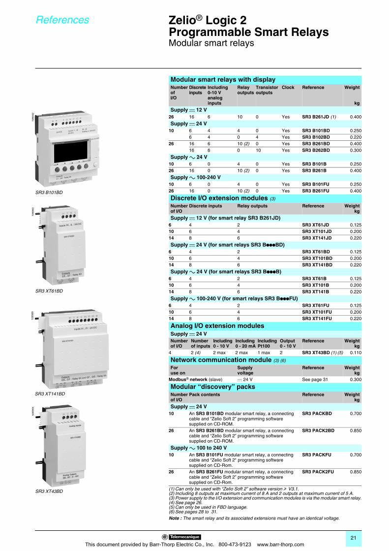
Modular smart relays
Modular smart relays with displayNumber ofI/O
Discrete inputs
Including 0-10 V analog inputs
Relay outputs
Transistor outputs
Clock Reference Weight
kg
Supply c 12 V26 16 6 10 0 Yes SR3 B261JD (1) 0.400
Supply c 24 V10 6 4 4 0 Yes SR3 B101BD 0.250
6 4 0 4 Yes SR3 B102BD 0.22026 16 6 10 (2) 0 Yes SR3 B261BD 0.400
16 6 0 10 Yes SR3 B262BD 0.300
Supply a 24 V10 6 0 4 0 Yes SR3 B101B 0.25026 16 0 10 (2) 0 Yes SR3 B261B 0.400
Supply a 100-240 V10 6 0 4 0 Yes SR3 B101FU 0.25026 16 0 10 (2) 0 Yes SR3 B261FU 0.400
Discrete I/O extension modules (3)
Number of I/O
Discrete inputs Relay outputs Reference Weightkg
Supply c 12 V (for smart relay SR3 B261JD)6 4 2 SR3 XT61JD 0.12510 6 4 SR3 XT101JD 0.20014 8 6 SR3 XT141JD 0.220
Supply c 24 V (for smart relays SR3 BpppBD)6 4 2 SR3 XT61BD 0.12510 6 4 SR3 XT101BD 0.20014 8 6 SR3 XT141BD 0.220
Supply a 24 V (for smart relays SR3 BpppB)6 4 2 SR3 XT61B 0.12510 6 4 SR3 XT101B 0.20014 8 6 SR3 XT141B 0.220
Supply a 100-240 V (for smart relays SR3 BpppFU)6 4 2 SR3 XT61FU 0.12510 6 4 SR3 XT101FU 0.20014 8 6 SR3 XT141FU 0.220
Analog I/O extension modulesSupply c 24 VNumber of I/O
Number of inputs
Including0 - 10 V
Including0 - 20 mA
IncludingPt100
Output0 - 10 V
Reference Weightkg
4 2 (4) 2 max 2 max 1 max 2 SR3 XT43BD (1) (5) 0.110
Network communication module (3) (6)
Foruse on
Supply voltage
Reference Weightkg
Modbus® network (slave) c 24 V See page 31 0.300
Modular “discovery” packsNumber of I/O
Pack contents Reference Weightkg
Supply c 24 V10 An SR3 B101BD modular smart relay, a connecting
cable and “Zelio Soft 2” programming software supplied on CD-ROM.
SR3 PACKBD 0.700
26 An SR3 B261BD modular smart relay, a connecting cable and “Zelio Soft 2” programming software supplied on CD-ROM.
SR3 PACK2BD 0.850
Supply a 100 to 240 V10 An SR3 B101FU modular smart relay, a connecting
cable and “Zelio Soft 2" programming software supplied on CD-Rom.
SR3 PACKFU 0.700
26 An SR3 B261FU modular smart relay, a connecting cable and “Zelio Soft 2” programming software supplied on CD-Rom.
SR3 PACK2FU 0.850
(1) Can only be used with “Zelio Soft 2” software version u V3.1.(2) Including 8 outputs at maximum current of 8 A and 2 outputs at maximum current of 5 A.(3) Power supply to the I/O extension and communication modules is via the modular smart relay.(4) See page 26.(5) Can only be used in FBD language.(6) See pages 28 to 31.Note : The smart relay and its associated extensions must have an identical voltage.
1094
42
SR3 B101BD
1093
63
SR3 XT61BD
1093
69
SR3 XT141BD
5349
45
SR3 XT43BD
This document provided by Barr-Thorp Electric Co., Inc. 800-473-9123 www.barr-thorp.com
22
References 0 Zelio® Logic 2Programmable Smart Relays 0
Compact and modular smart relaysSeparate components
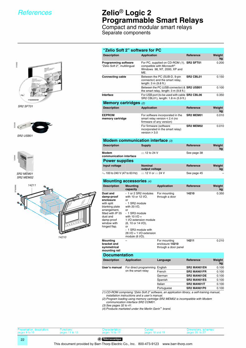
“Zelio Soft 2” software for PCDescription Application Reference Weight
kgProgramming software “Zelio Soft 2”, multilingual
For PC, supplied on CD-ROM (1), compatible with Microsoft® Windows 98, NT, 2000, XP and ME.
SR2 SFT01 0.200
Connecting cable Between the PC (SUB-D, 9-pin connector) and the smart relay, length: 3 m (9.8 ft.)
SR2 CBL01 0.150
Between the PC (USB connector) & the smart relay, length: 3 m (9.8 ft.)
SR2 USB01 0.100
Interface For USB port (to be used with cable SR2 CBL01), length: 1.8 m (5.9 ft.)
SR2 CBL06 0.350
Memory cartridges (2)
Description Application Reference Weightkg
EEPROMmemory cartridge
For software incorporated in the smart relay version y 2.4 (no firmware of any version)
SR2 MEM01 0.010
For firmware (software incorporated in the smart relay) version u 3.0
SR2 MEM02 0.010
Modem communication interface (3)
Description Supply Reference Weightkg
Modem communication interface
c 12 to 24 V See page 38
Power suppliesInput voltage Nominal
output voltageReference Weight
kga 100 to 240 V (47 to 63 Hz) c 12 V or c 24 V See page 45 –
Mounting accessories (4)
Description Mounting capacity
Application Reference Weightkg
Dust and damp-proof enclosure with split blanking plate arrangement, fitted with IP 55 dust and damp-proof window with hinged flap.
- 1 or 2 SR2 modules with 10 or 12 I/O,or- 1 SR2 module with 20 I/O,or- 1 SR3 module with 10 I/O +1 I/O extension module (6, 10 or 14 I/O),or- 1 SR3 module with 26 I/O + 1 I/O extension module (6 I/O).
For mounting through a door
14210 0.350
Mounting bracket and symmetrical mounting rail
– For mounting enclosure 14210 through a door panel
14211 0.210
DocumentationDescription Application Language Reference Weight
kgUser’s manual For direct programming
on the smart relayEnglish SR2 MAN01EN 0.100French SR2 MAN01FR 0.100German SR2 MAN01DE 0.100Spanish SR2 MAN01ES 0.100Italian SR2 MAN01IT 0.100Portuguese SR2 MAN01P0 0.100
(1) CD-ROM comprising “Zelio Soft 2” software, an application library, a self-training manual, installation instructions and a user’s manual.
(2) Program loading using memory cartridge SR2 MEM02 is incompatible with Modem communication interface SR2 COM01.
(3) See pages 32 to 41.(4) Products marketed under the Merlin Gerin™ brand.
SR2 SFT01
5103
52
SR2 USB01
5231
0953
4944
SR2 MEM01SR2 MEM02
14210
14211
DF
5639
90
Presentation, description:pages 8 to 10
Functions:pages 11 to 13
Characteristics:pages 14 to 17
Curves:pages 18 and 19
Dimensions, schemes:pages 23 to 27
This document provided by Barr-Thorp Electric Co., Inc. 800-473-9123 www.barr-thorp.com
23
Dimensions,mounting 0
Zelio® Logic 2Programmable Smart Relays 0
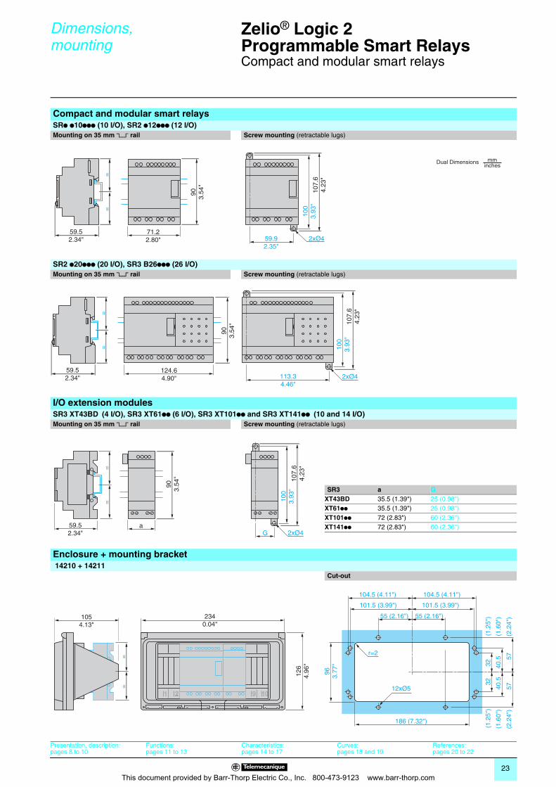
Compact and modular smart relays
Compact and modular smart relaysSRp p10ppp (10 I/O), SR2 p12ppp (12 I/O)Mounting on 35 mm 5 rail Screw mounting (retractable lugs)
SR2 p20ppp (20 I/O), SR3 B26ppp (26 I/O)Mounting on 35 mm 5 rail Screw mounting (retractable lugs)
I/O extension modulesSR3 XT43BD (4 I/O), SR3 XT61pp (6 I/O), SR3 XT101pp and SR3 XT141pp (10 and 14 I/O)Mounting on 35 mm 5 rail Screw mounting (retractable lugs)
SR3 a GXT43BD 35.5 (1.39") 25 (0.98")XT61pp 35.5 (1.39") 25 (0.98")XT101pp 72 (2.83") 60 (2.36")XT141pp 72 (2.83") 60 (2.36")
Enclosure + mounting bracket 14210 + 14211
Cut-out
71.22.80"
903.
54"
==
107.
64.
23"
59.52.34" 59.9
2.35"2xØ4
100
3.93
"
Dual Dimensions mminches
124.64.90"
903.
54"
113.34.46"
100
3.93
"
==
59.52.34" 2xØ4
107.
64.
23"
a
==
59.52.34" G
100
3.93
"10
7.6
4.23
"
903.
54"
2xØ4
186 (7.32")
963.
77" 32
(1.
25")
(1.2
5")
32
40.5
(
1.60
")
57
(2.2
4")
(2.2
4")
5
7
(1.6
0")
4
0.5
55 (2.16")
12xØ5
r=2
101.5 (3.99") 101.5 (3.99")
104.5 (4.11") 104.5 (4.11")
55 (2.16")2340.04"
1054.13"
126
4.96
"
==
Presentation, description:pages 8 to 10
Functions:pages 11 to 13
Characteristics:pages 14 to 17
Curves:pages 18 and 19
References:pages 20 to 22
This document provided by Barr-Thorp Electric Co., Inc. 800-473-9123 www.barr-thorp.com
24
Schemes 0 Zelio® Logic 2Programmable Smart Relays 0
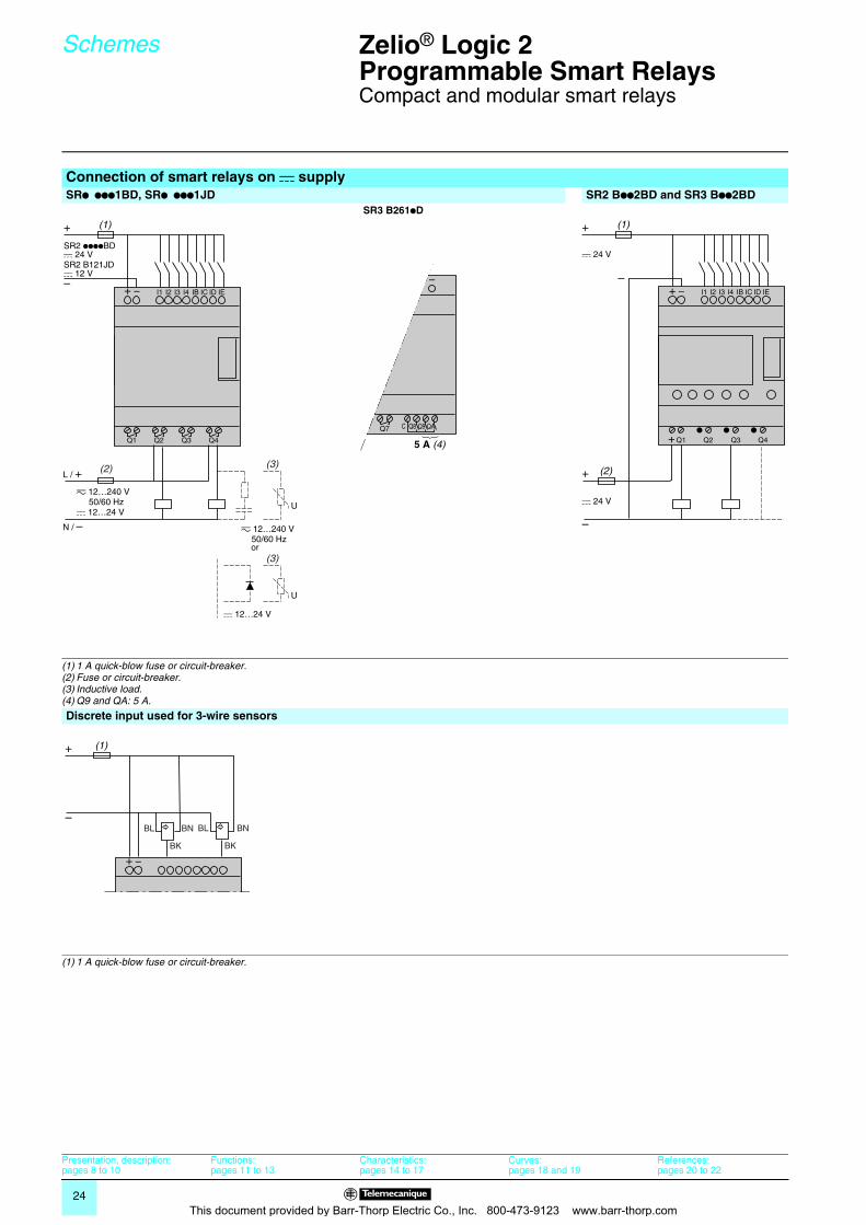
Compact and modular smart relays
Connection of smart relays on c supplySRp ppp1BD, SRp ppp1JD SR2 Bpp2BD and SR3 Bpp2BD SR3 B261pD
(1) 1 A quick-blow fuse or circuit-breaker.(2) Fuse or circuit-breaker.(3) Inductive load.(4) Q9 and QA: 5 A.
Discrete input used for 3-wire sensors
(1) 1 A quick-blow fuse or circuit-breaker.
+
SR2 B121JDc 12 V
SR2 ppppBDc 24 V
–
(1)
+ –
Q1 Q2 Q3 Q4
z 12…240 V 50/60 Hzc 12…24 V
L / +
N / – z 12…240 V 50/60 Hz
c 12…24 V
(2) (3)
I1 I2 I3 I4 IB IC ID IE
U
(3)
U
or
–
6 Q7 C Q8 Q9 QA
IA IB IC ID IE IF IG
5 A (4)
+ –
+
c 24 V
c 24 V
–
+
–
(1)
+Q1 Q2 Q3 Q4
I1 I2 I3 I4 IB IC ID IE
(2)
+ –
BN
BK
BLBN
BK
BL
+
–
(1)
+ –
Presentation, description:pages 8 to 10
Functions:pages 11 to 13
Characteristics:pages 14 to 17
Curves:pages 18 and 19
References:pages 20 to 22
This document provided by Barr-Thorp Electric Co., Inc. 800-473-9123 www.barr-thorp.com
25
Schemes (continued) 0 Zelio® Logic 2Programmable Smart Relays 0
Compact and modular smart relays
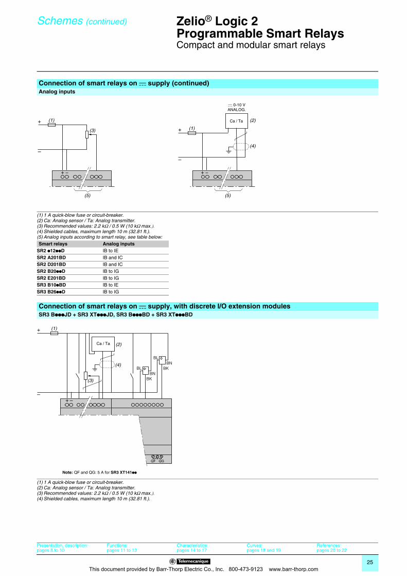
Connection of smart relays on c supply (continued)Analog inputs
(1) 1 A quick-blow fuse or circuit-breaker.(2) Ca: Analog sensor / Ta: Analog transmitter.(3) Recommended values: 2.2 kΩ / 0.5 W (10 kΩ max.).(4) Shielded cables, maximum length 10 m (32.81 ft.).(5) Analog inputs according to smart relay, see table below:Smart relays Analog inputs
SR2 p12ppD IB to IESR2 A201BD IB and ICSR2 D201BD IB and ICSR2 B20ppD IB to IGSR2 E201BD IB to IGSR3 B10pBD IB to IESR3 B26ppD IB to IG
Connection of smart relays on c supply, with discrete I/O extension modulesSR3 BpppJD + SR3 XTpppJD, SR3 BpppBD + SR3 XTpppBD
(1) 1 A quick-blow fuse or circuit-breaker.(2) Ca: Analog sensor / Ta: Analog transmitter.(3) Recommended values: 2.2 kΩ / 0.5 W (10 kΩ max.).(4) Shielded cables, maximum length 10 m (32.81 ft.).
+ –
+
–
(1)
(3)
(5)
+ –
+
–
(1)
Ca / Ta (2)
(5)
(4)
c 0-10 VANALOG.
+
–
(1)
(3)
Ca / Ta (2)
QB QC QD QE QF QG
+ –
BNBK
BLBN
BK
BL
(4)
Note: QF and QG: 5 A for SR3 XT141pp
Presentation, description:pages 8 to 10
Functions:pages 11 to 13
Characteristics:pages 14 to 17
Curves:pages 18 and 19
References:pages 20 to 22
This document provided by Barr-Thorp Electric Co., Inc. 800-473-9123 www.barr-thorp.com
26
Schemes (continued) 0 Zelio® Logic 2Programmable Smart Relays 0
Compact and modular smart relays
Presentation, description:pages 8 to 10
Functions:pages 11 to 13
Characteristics:pages 14 to 17
Curves:pages 18 and 19
References:pages 20 to 22
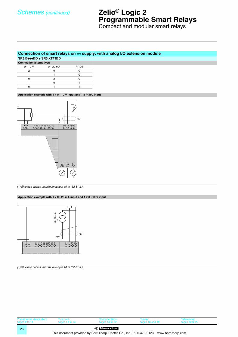
Connection of smart relays on c supply, with analog I/O extension moduleSR3 BpppBD + SR3 XT43BDConnection alternatives
0 - 10 V 0 - 20 mA Pt100 2 0 01 1 00 2 01 0 10 1 1
Application example with 1 x 0 - 10 V input and 1 x Pt100 input
(1) Shielded cables, maximum length 10 m (32.81 ft.).
Application example with 1 x 0 - 20 mA input and 1 x 0 - 10 V input
(1) Shielded cables, maximum length 10 m (32.81 ft.).
+
–IH IJ Pt
QB 0V QC
0V+ –
Q1 Q2 Q3 Q4
I1 I2 I3 I4 IB IC ID IE
(1)
+
–+ – I1 I2 I3 I4 IB IC ID IE IH IJ Pt 0V
(1)
0 -
20 m
A
This document provided by Barr-Thorp Electric Co., Inc. 800-473-9123 www.barr-thorp.com
27
Schemes (continued) 0 Zelio® Logic 2Programmable Smart Relays 0
Compact and modular smart relays
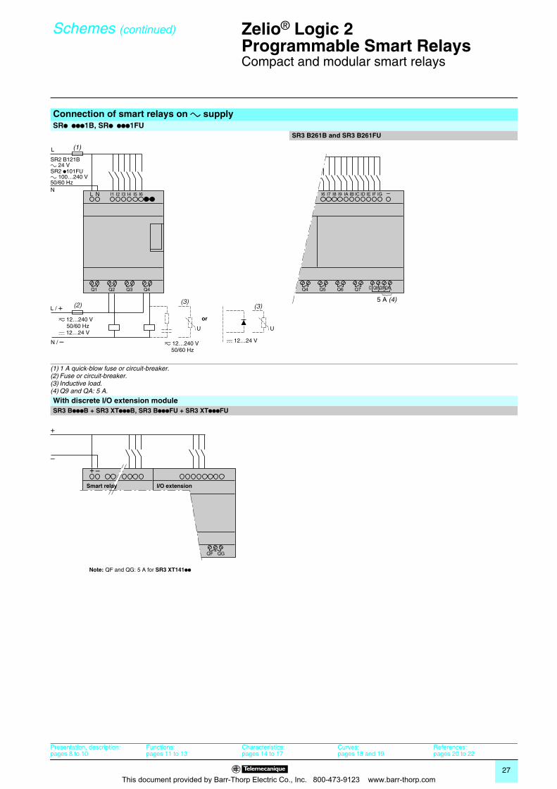
Connection of smart relays on a supplySRp ppp1B, SRp ppp1FU
SR3 B261B and SR3 B261FU
(1) 1 A quick-blow fuse or circuit-breaker.(2) Fuse or circuit-breaker.(3) Inductive load.(4) Q9 and QA: 5 A.
With discrete I/O extension moduleSR3 BpppB + SR3 XTpppB, SR3 BpppFU + SR3 XTpppFU
L
L N
SR2 p101FUa 100…240 V50/60 Hz
SR2 B121Ba 24 V
N
(1)
Q1 Q2 Q3 Q4
z 12…240 V 50/60 Hzc 12…24 V
L / +
N / – z 12…240 V 50/60 Hz
c 12…24 V
(2) (3)
I1 I2 I3 I4 I5 I6
U
(3)
U
or
+ – –
Q4 Q5 Q6 Q7 C Q8 Q9 QA
I6 I7 I8 I9 IA IB IC ID IE IF IG
5 A (4)
+
–
QB QC QD QE QF QG
+ –
Smart relay I/O extension
Note: QF and QG: 5 A for SR3 XT141pp
Presentation, description:pages 8 to 10
Functions:pages 11 to 13
Characteristics:pages 14 to 17
Curves:pages 18 and 19
References:pages 20 to 22
This document provided by Barr-Thorp Electric Co., Inc. 800-473-9123 www.barr-thorp.com
28
Presentation 0 Zelio® Logic 2Programmable Smart Relays 0
Modbus® network slave communication module
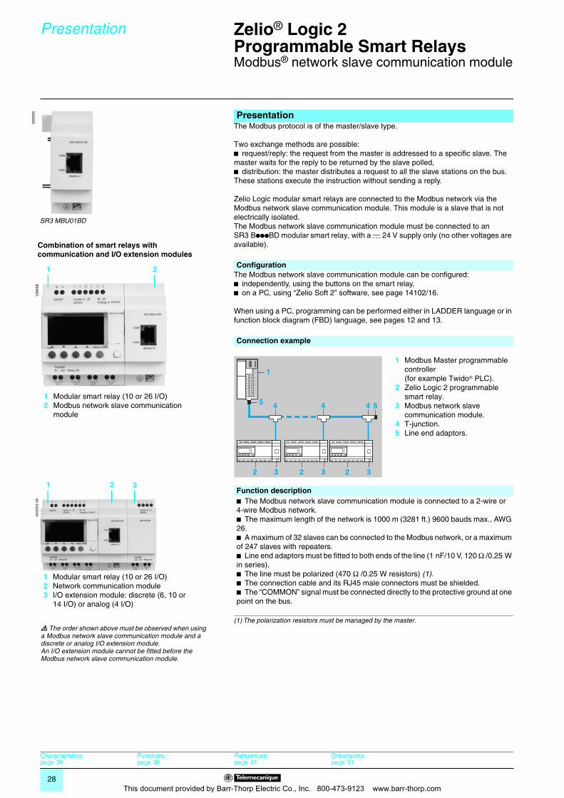
The Modbus protocol is of the master/slave type.
Two exchange methods are possible:b request/reply: the request from the master is addressed to a specific slave. The master waits for the reply to be returned by the slave polled,b distribution: the master distributes a request to all the slave stations on the bus. These stations execute the instruction without sending a reply.
Zelio Logic modular smart relays are connected to the Modbus network via the Modbus network slave communication module. This module is a slave that is not electrically isolated.The Modbus network slave communication module must be connected to an SR3 BpppBD modular smart relay, with a c 24 V supply only (no other voltages are available).
The Modbus network slave communication module can be configured:b independently, using the buttons on the smart relay,b on a PC, using “Zelio Soft 2” software, see page 14102/16.
When using a PC, programming can be performed either in LADDER language or in function block diagram (FBD) language, see pages 12 and 13.
Presentation
0000
05
SR3 MBU01BD
1094
58
1 2
1 Modular smart relay (10 or 26 I/O)2 Modbus network slave communication
module
Combination of smart relays with communication and I/O extension modules
Configuration
Connection example
1 Modbus Master programmable controller(for example Twido® PLC).
2 Zelio Logic 2 programmable smart relay.
3 Modbus network slave communication module.
4 T-junction.5 Line end adaptors.
Function descriptionb The Modbus network slave communication module is connected to a 2-wire or 4-wire Modbus network.b The maximum length of the network is 1000 m (3281 ft.) 9600 bauds max., AWG 26.b A maximum of 32 slaves can be connected to the Modbus network, or a maximum of 247 slaves with repeaters.b Line end adaptors must be fitted to both ends of the line (1 nF/10 V, 120 Ω /0.25 W in series).b The line must be polarized (470 Ω /0.25 W resistors) (1).b The connection cable and its RJ45 male connectors must be shielded.b The “COMMON” signal must be connected directly to the protective ground at one point on the bus.
(1) The polarization resistors must be managed by the master.
1
4
2 2 2
4 4 5
3 3 3
5
0000
03-2
6
1 2
1 Modular smart relay (10 or 26 I/O)2 Network communication module3 I/O extension module: discrete (6, 10 or
14 I/O) or analog (4 I/O)
3
d The order shown above must be observed when using a Modbus network slave communication module and a discrete or analog I/O extension module.An I/O extension module cannot be fitted before the Modbus network slave communication module.
Characteristics:page 29
Functions:page 30
References:page 31
Dimensions:page 31
This document provided by Barr-Thorp Electric Co., Inc. 800-473-9123 www.barr-thorp.com
29
Description, characteristics 0
Zelio® Logic 2Programmable Smart Relays 0
Modbus® network slave communication module
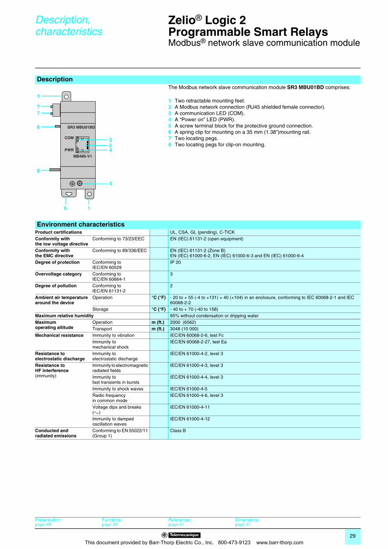
Description The Modbus network slave communication module SR3 MBU01BD comprises:
1 Two retractable mounting feet.2 A Modbus network connection (RJ45 shielded female connector). 3 A communication LED (COM).4 A “Power on” LED (PWR).5 A screw terminal block for the protective ground connection.6 A spring clip for mounting on a 35 mm (1.38”)mounting rail.7 Two locating pegs.8 Two locating pegs for clip-on mounting.
Environment characteristicsProduct certifications UL, CSA, GL (pending), C-TICKConformity with the low voltage directive
Conforming to 73/23/EEC EN (IEC) 61131-2 (open equipment)
Conformity with the EMC directive
Conforming to 89/336/EEC EN (IEC) 61131-2 (Zone B)EN (IEC) 61000-6-2, EN (IEC) 61000-6-3 and EN (IEC) 61000-6-4
Degree of protection Conforming to IEC/EN 60529
IP 20
Overvoltage category Conforming to IEC/EN 60664-1
3
Degree of pollution Conforming to IEC/EN 61131-2
2
Ambient air temperature around the device
Operation °C (°F) - 20 to + 55 (-4 to +131) + 40 (+104) in an enclosure, conforming to IEC 60068-2-1 and IEC 60068-2-2
Storage °C (°F) - 40 to + 70 (-40 to 158)Maximum relative humidity 95% without condensation or dripping waterMaximum operating altitude
Operation m (ft.) 2000 (6562)Transport m (ft.) 3048 (10 000)
Mechanical resistance Immunity to vibration IEC/EN 60068-2-6, test FcImmunity to mechanical shock
IEC/EN 60068-2-27, test Ea
Resistance to electrostatic discharge
Immunity to electrostatic discharge
IEC/EN 61000-4-2, level 3
Resistance to HF interference(immunity)
Immunity to electromagnetic radiated fields
IEC/EN 61000-4-3, level 3
Immunity to fast transients in bursts
IEC/EN 61000-4-4, level 3
Immunity to shock waves IEC/EN 61000-4-5Radio frequency in common mode
IEC/EN 61000-4-6, level 3
Voltage dips and breaks (a)
IEC/EN 61000-4-11
Immunity to damped oscillation waves
IEC/EN 61000-4-12
Conducted and radiated emissions
Conforming to EN 55022/11 (Group 1)
Class B
COM
SR3 MBU01BD
MB485-V1
PWR
6 1
8
8
2
5
3
4
1
77
Presentation:page 28
Functions:page 30
References:page 31
Dimensions:page 31
This document provided by Barr-Thorp Electric Co., Inc. 800-473-9123 www.barr-thorp.com
30
Functions 0 Zelio® Logic 2Programmable Smart Relays 0
Modbus® network slave communication module
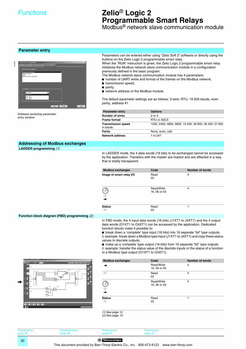
Parameter entryParameters can be entered either using “Zelio Soft 2” software or directly using the buttons on the Zelio Logic 2 programmable smart relay.When the “RUN” instruction is given, the Zelio Logic 2 programmable smart relay initializes the Modbus network slave communication module in a configuration previously defined in the basic program.The Modbus network slave communication module has 4 parameters:b number of UART wires and format of the frames on the Modbus network,b transmission speed,b parity,b network address of the Modbus module.
The default parameter settings are as follows: 2-wire, RTU, 19 200 bauds, even parity, address #1.
Parameter entry OptionsNumber of wires 2 or 4Frame format RTU or ASCIITransmission speedin bauds
1200, 2400, 4800, 9600, 19 200, 28 800, 38 400, 57 600
Parity None, even, oddNetwork address 1 to 247
Addressing of Modbus exchangesLADDER programming (1)
In LADDER mode, the 4 data words (16 bits) to be exchanged cannot be accessed by the application. Transfers with the master are implicit and are effected in a way that is totally transparent.
Modbus exchanges Code Number of words
Image of smart relay I/O Read03
4
C V
Read/Write16, 06 or 03
4
Status C
Read03
1
Function block diagram (FBD) programming (2) In FBD mode, the 4 input data words (16 bits) (J1XT1 to J4XT1) and the 4 output
data words (O1XT1 to O4XT1) can be accessed by the application. Dedicated function blocks make it possible to:b break down a ‘complete’ type input (16 bits) into 16 separate “bit” type outputs.v example: break down a Modbus type input (J1XT1 to J4XT1) and copy these status values to discrete outputs.b make up a ‘complete’ type output (16 bits) from 16 separate “bit” type outputs.v example: transfer the status value of the discrete inputs or the status of a function to a Modbus type output (O1XT1 to O4XT1).
Modbus exchanges Code Number of words
V Read/Write16, 06 or 03
4
C Read03
4
C V
Read/Write16, 06 or 03
4
Status C
Read03
1
(1) See page 12.(2) See page 13.
5103
91
Software workshop parameter entry window
V
Presentation:page 28
Characteristics:page 29
References:page 31
Dimensions:page 31
This document provided by Barr-Thorp Electric Co., Inc. 800-473-9123 www.barr-thorp.com
31
References,dimensions,mounting 0
Zelio® Logic 2Programmable Smart Relays 0
Modbus® network slave communication module
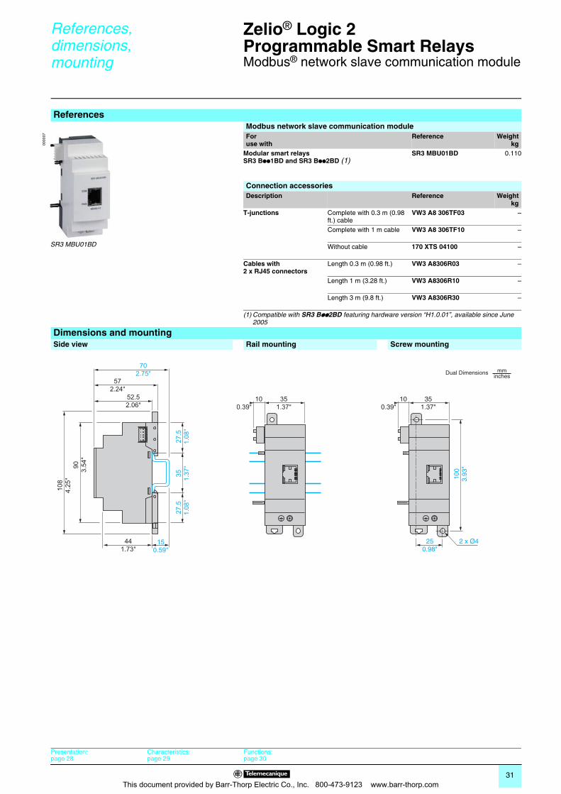
ReferencesModbus network slave communication moduleForuse with
Reference Weightkg
Modular smart relays SR3 Bpp1BD and SR3 Bpp2BD (1)
SR3 MBU01BD 0.110
Connection accessoriesDescription Reference Weight
kgT-junctions Complete with 0.3 m (0.98
ft.) cableVW3 A8 306TF03 –
Complete with 1 m cable VW3 A8 306TF10 –
Without cable 170 XTS 04100 –
Cables with 2 x RJ45 connectors
Length 0.3 m (0.98 ft.) VW3 A8306R03 –
Length 1 m (3.28 ft.) VW3 A8306R10 –
Length 3 m (9.8 ft.) VW3 A8306R30 –
(1) Compatible with SR3 Bpp2BD featuring hardware version “H1.0.01”, available since June 2005
Dimensions and mountingSide view Rail mounting Screw mounting
0000
07
SR3 MBU01BD
100.39"
572.24"
52.52.06"
702.75"
441.73"
150.59"
90 3.54
"
35 1.37
"27.5
1.08
"27.5
1.08
"
108
4.25
"
351.37"
100.39"
250.98"
351.37"
100
3.93
"
2 x Ø4
Dual Dimensions mminches
Presentation:page 28
Characteristics:page 29
Functions:page 30
This document provided by Barr-Thorp Electric Co., Inc. 800-473-9123 www.barr-thorp.com
32
Presentation Zelio® Logic 2Programmable Smart Relays 0
Modem communication interface
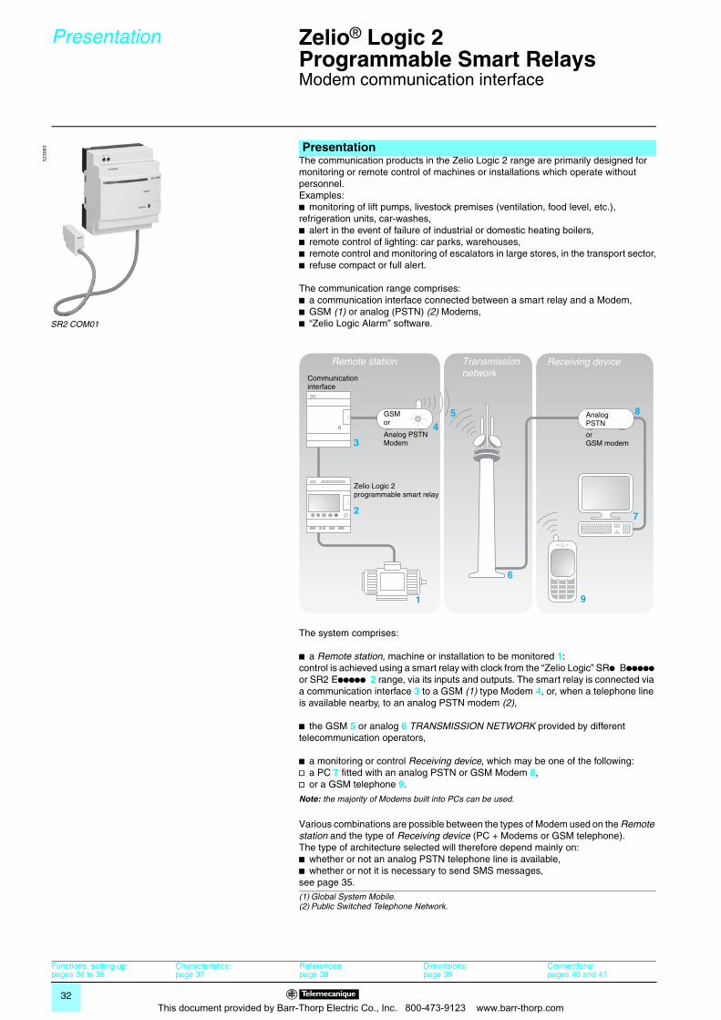
The communication products in the Zelio Logic 2 range are primarily designed for monitoring or remote control of machines or installations which operate without personnel.Examples: b monitoring of lift pumps, livestock premises (ventilation, food level, etc.), refrigeration units, car-washes,b alert in the event of failure of industrial or domestic heating boilers,b remote control of lighting: car parks, warehouses,b remote control and monitoring of escalators in large stores, in the transport sector,b refuse compact or full alert.
The communication range comprises:b a communication interface connected between a smart relay and a Modem,b GSM (1) or analog (PSTN) (2) Modems,b “Zelio Logic Alarm” software.
The system comprises:
b a Remote station, machine or installation to be monitored 1:control is achieved using a smart relay with clock from the “Zelio Logic” SRp Bppppp or SR2 Eppppp 2 range, via its inputs and outputs. The smart relay is connected via a communication interface 3 to a GSM (1) type Modem 4, or, when a telephone line is available nearby, to an analog PSTN modem (2),
b the GSM 5 or analog 6 TRANSMISSION NETWORK provided by different telecommunication operators,
b a monitoring or control Receiving device, which may be one of the following:v a PC 7 fitted with an analog PSTN or GSM Modem 8,v or a GSM telephone 9.
Note: the majority of Modems built into PCs can be used.
Various combinations are possible between the types of Modem used on the Remote station and the type of Receiving device (PC + Modems or GSM telephone). The type of architecture selected will therefore depend mainly on:b whether or not an analog PSTN telephone line is available,b whether or not it is necessary to send SMS messages,see page 35.
Presentation
SR2 COM01
5230
83
1
2
3
45
7
8
9
6
Remote station Transmission network
Receiving device
Communication interface
GSM or
Analog PSTNModem
Zelio Logic 2 programmable smart relay
Analog PSTN
orGSM modem
(1) Global System Mobile.(2) Public Switched Telephone Network.
Functions, setting-up:pages 34 to 35
Characteristics:page 37
References:page 38
Dimensions:page 39
Connections:pages 40 and 41
This document provided by Barr-Thorp Electric Co., Inc. 800-473-9123 www.barr-thorp.com
33
Presentation (continued)
descriptionZelio® Logic 2Programmable Smart Relays 0
Modem communication interface
The smart relay, as on an independent machine or installation, is used for control (1). It contains the application program created using “Zelio Soft 2” software. The smart relay may be selected from the various models in the Zelio Logic 2 range: b for all supply voltages,b with 10, 12, 20 or 26 I/O (up to 40 I/O with discrete extension module),b with or without display,b with clock.The firmware version of the smart relay must be V3.1. or above.
The Modem communication interface allows messages, telephone numbers and calling conditions to be stored.When the calling conditions are met, the messages, as well as any values to be sent, are date-stamped and stored in the interface.The Modem communication interface scales analog values to the physical values (degree, bar, Pascal, etc.) required by the user.
Either GSM or analog PSTN type Modems can be used on both the Remote station and PC type Receiving devices (when the PC is not fitted with an internal Modem).
In order to exploit all the capabilities associated with Modem communication, the Modem(s) must be fitted with DATA type SIM cards. VOICE type SIM cards may be used but some functions will not be available. See table on page 35.
This software makes it possible to:b receive, classify and export alarm messages,b read or remotely force the status of program elements (inputs, outputs, control relays, timing or counting values, etc.),b send control instructions (RUN, STOP, setting the time of the smart relay, etc.),b send specific instructions (modifying access rights, recipients, etc.).
Presentation (continued)Smart relay (Remote station)
Modem communication interface (Remote station)
Modems
GSM modem
“Zelio Logic Alarm” alarm management software (PC type Receiving device)
(1) Zelio Logic smart relays, see pages 8 to 28.
Functions, setting-up:pages 34 to 35
Characteristics:page 37
References:page 38
Dimensions:page 39
Connections:pages 40 and 41
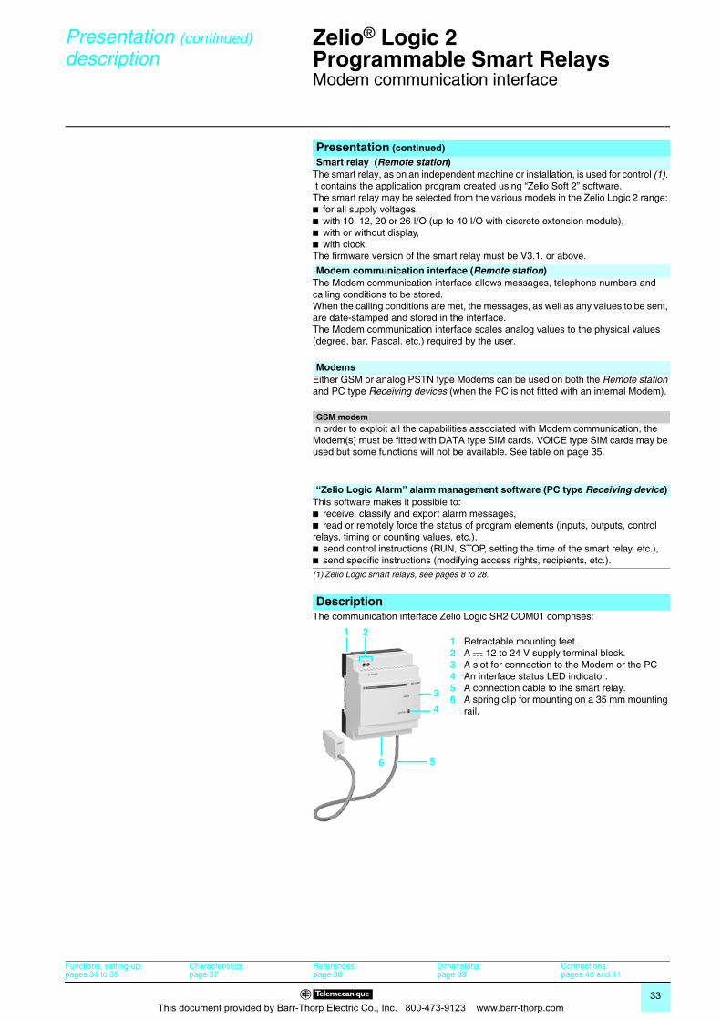
DescriptionThe communication interface Zelio Logic SR2 COM01 comprises:
123456
Retractable mounting feet.A c 12 to 24 V supply terminal block.A slot for connection to the Modem or the PCAn interface status LED indicator.A connection cable to the smart relay.A spring clip for mounting on a 35 mm mounting rail.
1 2
3
5
4
6
This document provided by Barr-Thorp Electric Co., Inc. 800-473-9123 www.barr-thorp.com
34
Functions Zelio® Logic 2Programmable Smart Relays 0
Modem communication interface
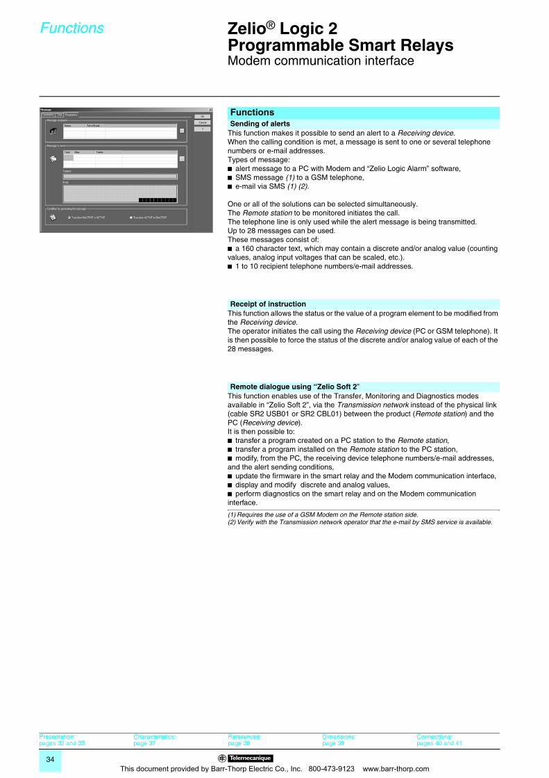
This function makes it possible to send an alert to a Receiving device.When the calling condition is met, a message is sent to one or several telephone numbers or e-mail addresses.Types of message:b alert message to a PC with Modem and “Zelio Logic Alarm” software,b SMS message (1) to a GSM telephone,b e-mail via SMS (1) (2).
One or all of the solutions can be selected simultaneously.The Remote station to be monitored initiates the call. The telephone line is only used while the alert message is being transmitted. Up to 28 messages can be used.These messages consist of: b a 160 character text, which may contain a discrete and/or analog value (counting values, analog input voltages that can be scaled, etc.).b 1 to 10 recipient telephone numbers/e-mail addresses.
This function allows the status or the value of a program element to be modified from the Receiving device.The operator initiates the call using the Receiving device (PC or GSM telephone). It is then possible to force the status of the discrete and/or analog value of each of the 28 messages.
This function enables use of the Transfer, Monitoring and Diagnostics modes available in “Zelio Soft 2”, via the Transmission network instead of the physical link (cable SR2 USB01 or SR2 CBL01) between the product (Remote station) and the PC (Receiving device).It is then possible to:b transfer a program created on a PC station to the Remote station,b transfer a program installed on the Remote station to the PC station,b modify, from the PC, the receiving device telephone numbers/e-mail addresses, and the alert sending conditions,b update the firmware in the smart relay and the Modem communication interface,b display and modify discrete and analog values,b perform diagnostics on the smart relay and on the Modem communication interface.
(1) Requires the use of a GSM Modem on the Remote station side.(2) Verify with the Transmission network operator that the e-mail by SMS service is available.
Functions Sending of alerts
Receipt of instruction
Remote dialogue using “Zelio Soft 2”
Presentation:pages 32 and 33
Characteristics:page 37
References:page 38
Dimensions:page 39
Connections:pages 40 and 41
This document provided by Barr-Thorp Electric Co., Inc. 800-473-9123 www.barr-thorp.com
35
Functions (continued) Zelio® Logic 2Programmable Smart Relays 0
Modem communication interface
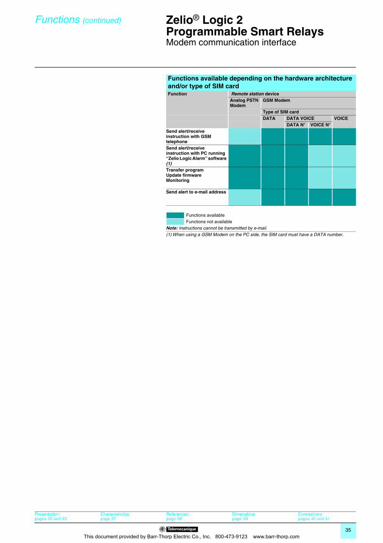
Functions available depending on the hardware architecture and/or type of SIM cardFunction Remote station device
Analog PSTN Modem
GSM Modem
Type of SIM cardDATA DATA VOICE VOICE
DATA N° VOICE N°Send alert/receive instruction with GSM telephoneSend alert/receive instruction with PC running “Zelio Logic Alarm” software (1)Transfer programUpdate firmware Monitoring
Send alert to e-mail address
Functions availableFunctions not available
Note: Instructions cannot be transmitted by e-mail.(1) When using a GSM Modem on the PC side, the SIM card must have a DATA number.
Presentation:pages 32 and 33
Characteristics:page 37
References:page 38
Dimensions:page 39
Connections:pages 40 and 41
This document provided by Barr-Thorp Electric Co., Inc. 800-473-9123 www.barr-thorp.com
36
Setting-up Zelio® Logic 2Programmable Smart Relays 0
Modem communication interface
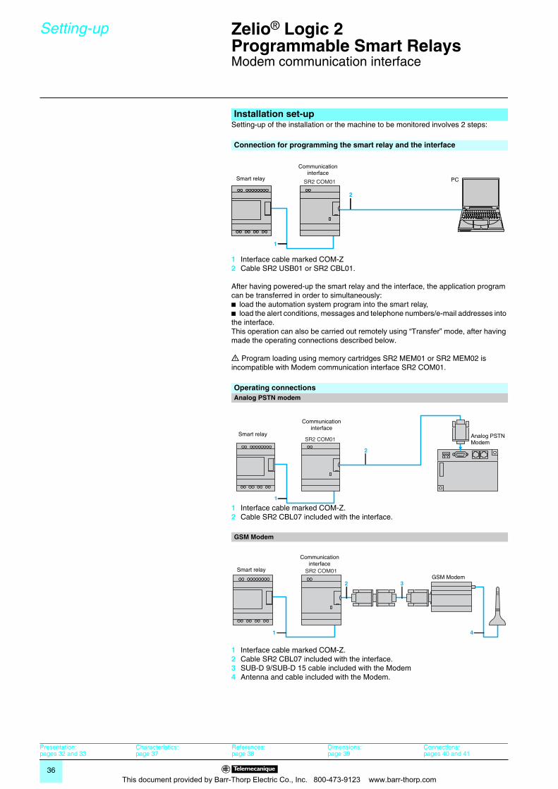
Setting-up of the installation or the machine to be monitored involves 2 steps:
1 Interface cable marked COM-Z2 Cable SR2 USB01 or SR2 CBL01.
After having powered-up the smart relay and the interface, the application program can be transferred in order to simultaneously: b load the automation system program into the smart relay,b load the alert conditions, messages and telephone numbers/e-mail addresses into the interface.This operation can also be carried out remotely using “Transfer” mode, after having made the operating connections described below.
d Program loading using memory cartridges SR2 MEM01 or SR2 MEM02 is incompatible with Modem communication interface SR2 COM01.
1 Interface cable marked COM-Z.2 Cable SR2 CBL07 included with the interface.
1 Interface cable marked COM-Z.2 Cable SR2 CBL07 included with the interface.3 SUB-D 9/SUB-D 15 cable included with the Modem4 Antenna and cable included with the Modem.
Installation set-up
Connection for programming the smart relay and the interface
SR2 COM01
1
2
Smart relay
Communication interface
PC
Operating connectionsAnalog PSTN modem
SR2 COM01
1
2
Analog PSTN Modem
Smart relay
Communication interface
GSM Modem
SR2 COM01
1 4
2 3GSM Modem
Smart relay
Communication interface
Presentation:pages 32 and 33
Characteristics:page 37
References:page 38
Dimensions:page 39
Connections:pages 40 and 41
This document provided by Barr-Thorp Electric Co., Inc. 800-473-9123 www.barr-thorp.com
37
Characteristics Zelio® Logic 2Programmable Smart Relays 0
Modem communication interface
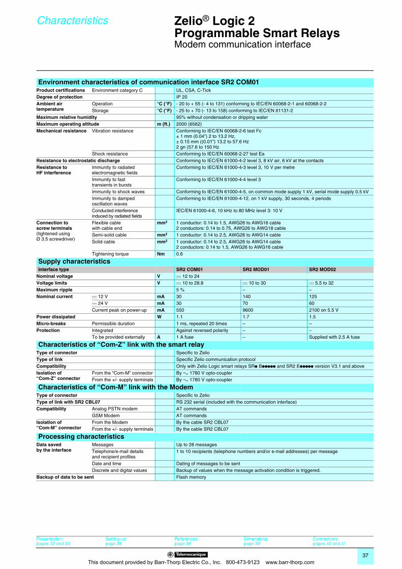
Environment characteristics of communication interface SR2 COM01Product certifications Environment category C UL, CSA, C-TickDegree of protection IP 20Ambient airtemperature
Operation °C (°F) - 20 to + 55 (- 4 to 131) conforming to IEC/EN 60068-2-1 and 60068-2-2Storage °C (°F) - 25 to + 70 (- 13 to 158) conforming to IEC/EN 61131-2
Maximum relative humidity 95% without condensation or dripping waterMaximum operating altitude m (ft.) 2000 (6562)Mechanical resistance Vibration resistance Conforming to IEC/EN 60068-2-6 test Fc
± 1 mm (0.04”) 2 to 13.2 Hz,± 0.15 mm ((0.01”) 13.2 to 57.6 Hz2 gn (57.6 to 150 Hz
Shock resistance Conforming to IEC/EN 60068-2-27 test EaResistance to electrostatic discharge Conforming to IEC/EN 61000-4-2 level 3, 8 kV air, 6 kV at the contactsResistance to HF interference
Immunity to radiated electromagnetic fields
Conforming to IEC/EN 61000-4-3 level 3, 10 V per metre
Immunity to fast transients in bursts
Conforming to IEC/EN 61000-4-4 level 3
Immunity to shock waves Conforming to IEC/EN 61000-4-5, on common mode supply 1 kV, serial mode supply 0.5 kVImmunity to damped oscillation waves
Conforming to IEC/EN 61000-4-12, on 1 kV supply, 30 seconds, 4 periods
Conducted interference induced by radiated fields
IEC/EN 61000-4-6, 10 kHz to 80 MHz level 3: 10 V
Connection to screw terminals(tightened using Ø 3.5 screwdriver)
Flexible cable with cable end
mm2 1 conductor: 0.14 to 1.5, AWG26 to AWG16 cable2 conductors: 0.14 to 0.75, AWG26 to AWG18 cable
Semi-solid cable mm2 1 conductor: 0.14 to 2.5, AWG26 to AWG14 cableSolid cable mm2 1 conductor: 0.14 to 2.5, AWG26 to AWG14 cable
2 conductors: 0.14 to 1.5, AWG26 to AWG16 cableTightening torque Nm 0.6
Supply characteristicsInterface type SR2 COM01 SR2 MOD01 SR2 MOD02
Nominal voltage V c 12 to 24Voltage limits V c 10 to 28.8 c 10 to 30 c 5.5 to 32Maximum ripple 5 % – –Nominal current c 12 V mA 30 140 125
c 24 V mA 30 70 60Current peak on power-up mA 550 9600 2100 on 5.5 V
Power dissipated W 1.1 1.7 1.5Micro-breaks Permissible duration 1 ms, repeated 20 times – –Protection Integrated Against reversed polarity – –
To be provided externally A 1 A fuse – Supplied with 2.5 A fuse
Characteristics of “Com-Z” link with the smart relayType of connector Specific to ZelioType of link Specific Zelio communication protocolCompatibility Only with Zelio Logic smart relays SRp Bppppp and SR2 Eppppp version V3.1 and aboveIsolation of “Com-Z” connector
From the “Com-M” connector By a 1780 V opto-couplerFrom the +/- supply terminals By a 1780 V opto-coupler
Characteristics of “Com-M” link with the ModemType of connector Specific to ZelioType of link with SR2 CBL07 RS 232 serial (included with the communication interface)Compatibility Analog PSTN modem AT commands
GSM Modem AT commandsIsolation of “Com-M” connector
From the Modem By the cable SR2 CBL07From the +/- supply terminals By the cable SR2 CBL07
Processing characteristicsData savedby the interface
Messages Up to 28 messagesTelephone/e-mail details and recipient profiles
1 to 10 recipients (telephone numbers and/or e-mail addresses) per message
Date and time Dating of messages to be sentDiscrete and digital values Backup of values when the message activation condition is triggered.
Backup of data to be sent Flash memory
Presentation:pages 32 and 33
Setting-up:page 36
References:page 38
Dimensions:page 39
Connections:pages 40 and 41
This document provided by Barr-Thorp Electric Co., Inc. 800-473-9123 www.barr-thorp.com
38
References Zelio® Logic 2Programmable Smart Relays 0
Modem communication interface
Modem communication interfaceDescription Supply
voltageReference Weight
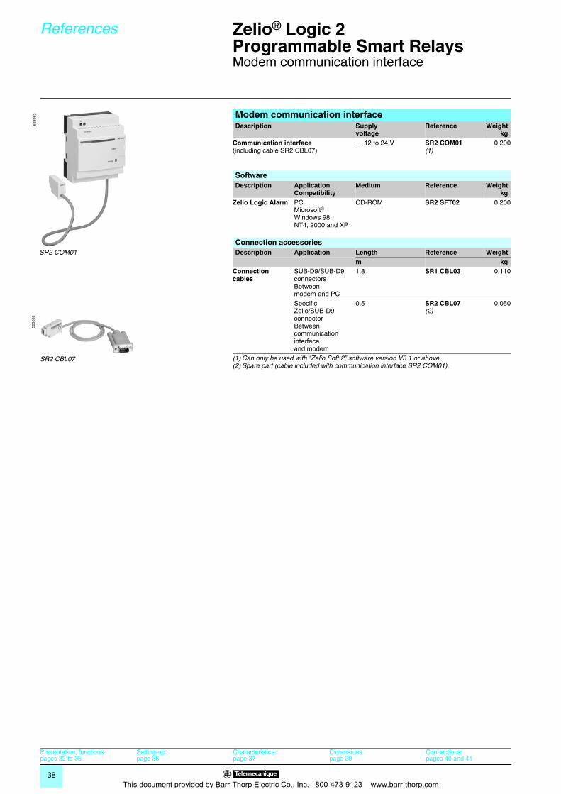
kgCommunication interface(including cable SR2 CBL07)
c 12 to 24 V SR2 COM01(1)
0.200
SoftwareDescription Application
CompatibilityMedium Reference Weight
kgZelio Logic Alarm PC
Microsoft® Windows 98,NT4, 2000 and XP
CD-ROM SR2 SFT02 0.200
Connection accessoriesDescription Application Length Reference Weight
m kgConnection cables
SUB-D9/SUB-D9 connectorsBetween modem and PC
1.8 SR1 CBL03 0.110
Specific Zelio/SUB-D9 connectorBetween communication interface and modem
0.5 SR2 CBL07(2)
0.050
(1) Can only be used with “Zelio Soft 2” software version V3.1 or above.(2) Spare part (cable included with communication interface SR2 COM01).
SR2 COM01
5230
83
SR2 CBL07
5230
86
Presentation, functions:pages 32 to 35
Setting-up:page 36
Characteristics:page 37
Dimensions:page 39
Connections:pages 40 and 41
This document provided by Barr-Thorp Electric Co., Inc. 800-473-9123 www.barr-thorp.com
39
Dimensions Zelio® Logic 2Programmable Smart Relays 0
Modem communication interface
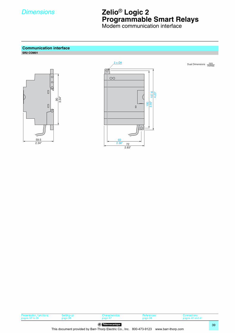
Communication interfaceSR2 COM01
602.36" 72
2.83"
59.52.34"
903.
54"
100
3.93
"10
7.6
4.23
"
2 x Ø4Dual Dimensions mm
inches
Presentation, functions:pages 32 to 35
Setting-up:page 36
Characteristics:page 37
References:page 38
Connections:pages 40 and 41
This document provided by Barr-Thorp Electric Co., Inc. 800-473-9123 www.barr-thorp.com
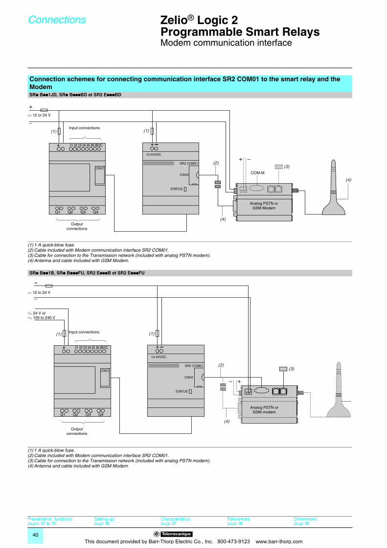
40
Connections Zelio® Logic 2Programmable Smart Relays 0
Modem communication interface
Connection schemes for connecting communication interface SR2 COM01 to the smart relay and the ModemSRp Bpp1JD, SRp BpppBD et SR2 EpppBD
(1) 1 A quick-blow fuse.(2) Cable included with Modem communication interface SR2 COM01.(3) Cable for connection to the Transmission network (included with analog PSTN modem).(4) Antenna and cable included with GSM Modem.
SRp Bpp1B, SRp BpppFU, SR2 EpppB et SR2 EpppFU
(1) 1 A quick-blow fuse.(2) Cable included with Modem communication interface SR2 COM01.(3) Cable for connection to the Transmission network (included with analog PSTN modem).(4) Antenna and cable included with GSM Modem.
(1)
(2)
(4)
(4)
+
12-24VDC
SR2 COM01
COM-M
COM-Z
STATUS
+ I1 I2 I3 I4 I5 I6 IBIC
Q1 Q2 Q3 Q4
(3)COM-M
–+
(1)
c 12 or 24 V
Input connections
Output connections
Analog PSTN or GSM Modem
(1)
(3)(2)
(
+
12-24VDC
SR2 COM01
COM-M
COM-Z
STATUS
+ I1 I2 I3 I4 I5 I6 IBIC
Q1 Q2 Q3 Q4
– +
(4)
(1)
c 12 to 24 V
Input connections
Output connections
Analog PSTN or GSM modem
a 24 V or a 100 to 240 V
Presentation, functions:pages 32 to 35
Setting-up:page 36
Characteristics:page 37
References:page 38
Dimensions:page 39
This document provided by Barr-Thorp Electric Co., Inc. 800-473-9123 www.barr-thorp.com
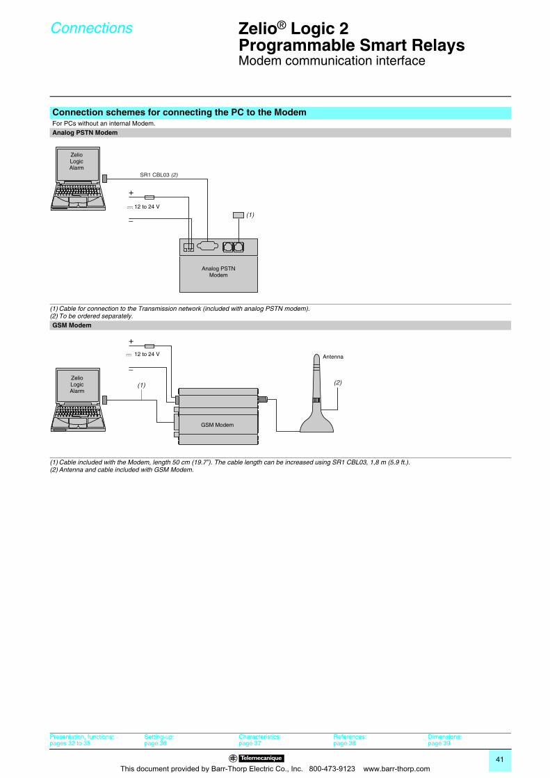
41
Connections Zelio® Logic 2Programmable Smart Relays 0
Modem communication interface
Connection schemes for connecting the PC to the ModemFor PCs without an internal Modem.Analog PSTN Modem
(1) Cable for connection to the Transmission network (included with analog PSTN modem).(2) To be ordered separately.GSM Modem
(1) Cable included with the Modem, length 50 cm (19.7”). The cable length can be increased using SR1 CBL03, 1,8 m (5.9 ft.).(2) Antenna and cable included with GSM Modem.
(1)
SR1 CBL03 (2)
c 12 to 24 V
ZelioLogicAlarm
Analog PSTN Modem
(1) (2)
c 12 to 24 V
GSM Modem
Antenna
ZelioLogicAlarm
Presentation, functions:pages 32 to 35
Setting-up:page 36
Characteristics:page 37
References:page 38
Dimensions:page 39
This document provided by Barr-Thorp Electric Co., Inc. 800-473-9123 www.barr-thorp.com
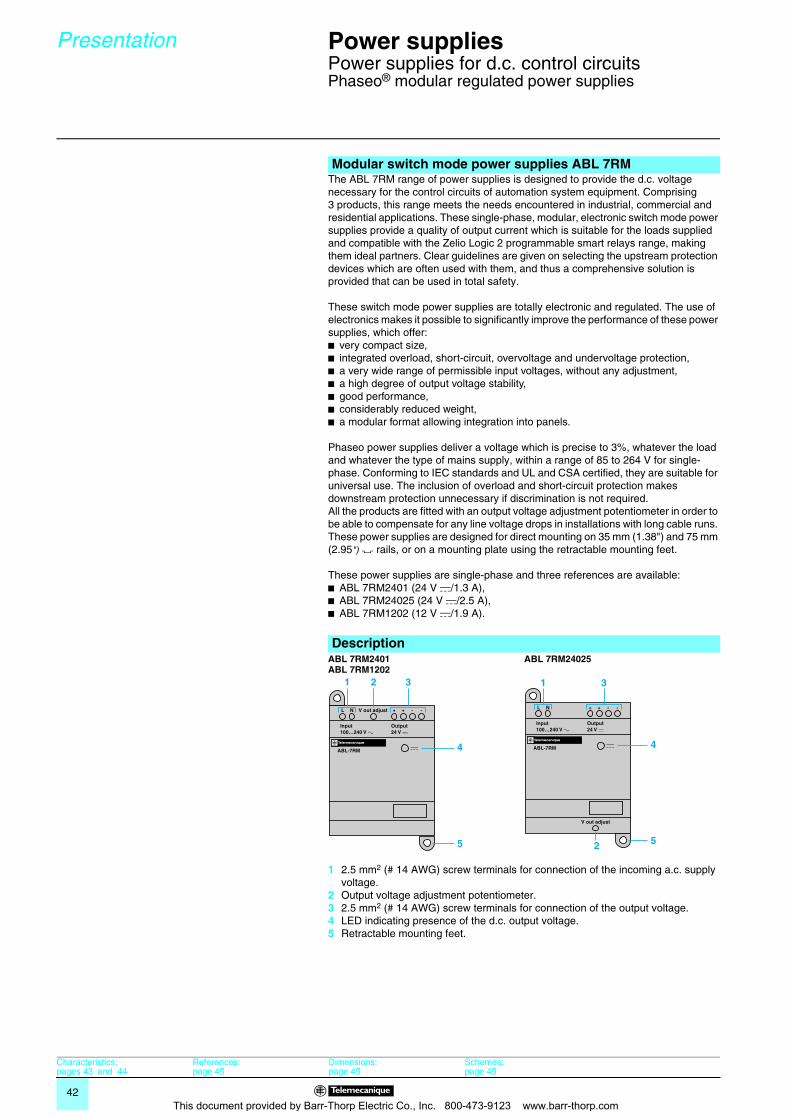
42
Presentation 0 Power supplies 0
Power supplies for d.c. control circuitsPhaseo® modular regulated power supplies
The ABL 7RM range of power supplies is designed to provide the d.c. voltage necessary for the control circuits of automation system equipment. Comprising 3 products, this range meets the needs encountered in industrial, commercial and residential applications. These single-phase, modular, electronic switch mode power supplies provide a quality of output current which is suitable for the loads supplied and compatible with the Zelio Logic 2 programmable smart relays range, making them ideal partners. Clear guidelines are given on selecting the upstream protection devices which are often used with them, and thus a comprehensive solution is provided that can be used in total safety.
These switch mode power supplies are totally electronic and regulated. The use of electronics makes it possible to significantly improve the performance of these power supplies, which offer:b very compact size,b integrated overload, short-circuit, overvoltage and undervoltage protection,b a very wide range of permissible input voltages, without any adjustment,b a high degree of output voltage stability,b good performance,b considerably reduced weight,b a modular format allowing integration into panels.
Phaseo power supplies deliver a voltage which is precise to 3%, whatever the load and whatever the type of mains supply, within a range of 85 to 264 V for single-phase. Conforming to IEC standards and UL and CSA certified, they are suitable for universal use. The inclusion of overload and short-circuit protection makes downstream protection unnecessary if discrimination is not required.All the products are fitted with an output voltage adjustment potentiometer in order to be able to compensate for any line voltage drops in installations with long cable runs. These power supplies are designed for direct mounting on 35 mm (1.38") and 75 mm (2.95") 7 rails, or on a mounting plate using the retractable mounting feet.
These power supplies are single-phase and three references are available:b ABL 7RM2401 (24 V c/1.3 A),b ABL 7RM24025 (24 V c/2.5 A),b ABL 7RM1202 (12 V c/1.9 A).
Modular switch mode power supplies ABL 7RM
DescriptionABL 7RM2401ABL 7RM1202
ABL 7RM24025
1 2.5 mm2 (# 14 AWG) screw terminals for connection of the incoming a.c. supply voltage.
2 Output voltage adjustment potentiometer.3 2.5 mm2 (# 14 AWG) screw terminals for connection of the output voltage.4 LED indicating presence of the d.c. output voltage.5 Retractable mounting feet.
21 3
4
5 2
1 3
4
5
Characteristics:pages 43 and 44
References:page 45
Dimensions:page 45
Schemes:page 45
This document provided by Barr-Thorp Electric Co., Inc. 800-473-9123 www.barr-thorp.com
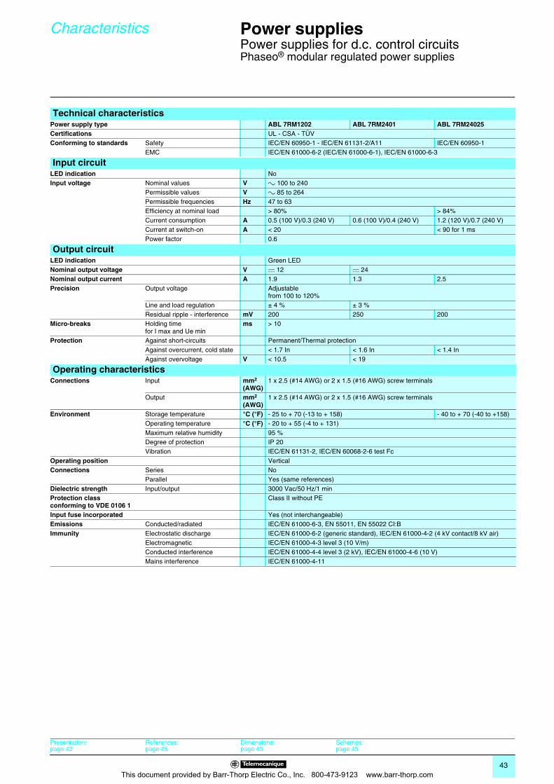
43
Characteristics 0 Power supplies 0
Power supplies for d.c. control circuitsPhaseo® modular regulated power supplies
Technical characteristicsPower supply type ABL 7RM1202 ABL 7RM2401 ABL 7RM24025Certifications UL - CSA - TÜVConforming to standards Safety IEC/EN 60950-1 - IEC/EN 61131-2/A11 IEC/EN 60950-1
EMC IEC/EN 61000-6-2 (IEC/EN 61000-6-1), IEC/EN 61000-6-3
Input circuitLED indication NoInput voltage Nominal values V a 100 to 240
Permissible values V a 85 to 264Permissible frequencies Hz 47 to 63Efficiency at nominal load > 80% > 84%Current consumption A 0.5 (100 V)/0.3 (240 V) 0.6 (100 V)/0.4 (240 V) 1.2 (120 V)/0.7 (240 V)Current at switch-on A < 20 < 90 for 1 msPower factor 0.6
Output circuitLED indication Green LEDNominal output voltage V c 12 c 24Nominal output current A 1.9 1.3 2.5Precision Output voltage Adjustable
from 100 to 120%Line and load regulation ± 4 % ± 3 %Residual ripple - interference mV 200 250 200
Micro-breaks Holding time for I max and Ue min
ms > 10
Protection Against short-circuits Permanent/Thermal protectionAgainst overcurrent, cold state < 1.7 In < 1.6 In < 1.4 InAgainst overvoltage V < 10.5 < 19
Operating characteristicsConnections Input mm2
(AWG)1 x 2.5 (#14 AWG) or 2 x 1.5 (#16 AWG) screw terminals
Output mm2
(AWG)1 x 2.5 (#14 AWG) or 2 x 1.5 (#16 AWG) screw terminals
Environment Storage temperature °C (°F) - 25 to + 70 (-13 to + 158) - 40 to + 70 (-40 to +158)Operating temperature °C (°F) - 20 to + 55 (-4 to + 131)Maximum relative humidity 95 %Degree of protection IP 20Vibration IEC/EN 61131-2, IEC/EN 60068-2-6 test Fc
Operating position VerticalConnections Series No
Parallel Yes (same references)Dielectric strength Input/output 3000 Vac/50 Hz/1 minProtection class conforming to VDE 0106 1
Class II without PE
Input fuse incorporated Yes (not interchangeable)Emissions Conducted/radiated IEC/EN 61000-6-3, EN 55011, EN 55022 CI:BImmunity Electrostatic discharge IEC/EN 61000-6-2 (generic standard), IEC/EN 61000-4-2 (4 kV contact/8 kV air)
Electromagnetic IEC/EN 61000-4-3 level 3 (10 V/m)Conducted interference IEC/EN 61000-4-4 level 3 (2 kV), IEC/EN 61000-4-6 (10 V)Mains interference IEC/EN 61000-4-11
Presentation:page 42
References:page 45
Dimensions:page 45
Schemes:page 45
This document provided by Barr-Thorp Electric Co., Inc. 800-473-9123 www.barr-thorp.com
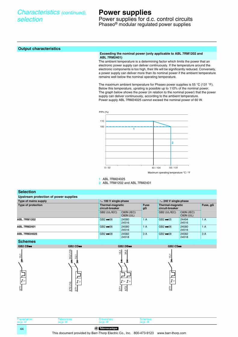
44
Characteristics (continued),
selection 0
Power supplies 0
Power supplies for d.c. control circuitsPhaseo® modular regulated power supplies
The ambient temperature is a determining factor which limits the power that an electronic power supply can deliver continuously. If the temperature around the electronic components is too high, their life will be significantly reduced. Conversely, a power supply can deliver more than its nominal power if the ambient temperature remains well below the nominal operating temperature.
The maximum ambient temperature for Phaseo power supplies is 55 °C (131 °F). Below this temperature, uprating is possible up to 110% of the nominal power. The graph below shows the power (in relation to the nominal power) that the power supply can deliver continuously, according to the ambient temperature.Power supply ABL 7RM24025 cannot exceed the nominal power of 60 W.
1 ABL 7RM240252 ABL 7RM1202 and ABL 7RM2401
Output characteristicsExceeding the nominal power (only applicable to ABL 7RM1202 and ABL 7RM2401)
0 / 32 40 / 104
110
100
55 / 131
2
1
P/Pn (%)
Maximum operating temperature °C / °F
SelectionUpstream protection of power suppliesType of mains supply a 100 V single-phase a 240 V single-phaseType of protection Thermal-magnetic
circuit-breakerFusegG
Thermal-magnetic circuit-breaker
Fuse, gG
GB2 (UL/IEC) C60N (IEC)C60N (UL)
GB2 (UL/IEC) C60N (IEC)C60N (UL)
ABL 7RM1202 GB2 pp06 24580 24516
1 A GB2 pp05 24494 24516
1 A
ABL 7RM2401 GB2 pp06 2458024516
1 A GB2 pp06 2458024516
1 A
ABL 7RM24025 GB2 pp08 2458224518
3 A GB2 pp08 2458224518
3 A
SchemesGB2 CBpp GB2 CDpp GB2 DBpp GB2 CSpp
2/T
11/
L1
2/T
1
4/T
2 (1
4)
1/L1
3/L2
(13
)
2/T
1
4/T
2
1/L1
3/L2
2/T
11/
L1
Presentation:page 42
References:page 45
Dimensions:page 45
Schemes:page 45
This document provided by Barr-Thorp Electric Co., Inc. 800-473-9123 www.barr-thorp.com
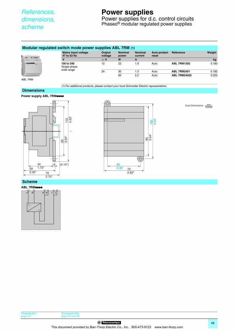
45
References, dimensions,scheme 0
Power supplies 0
Power supplies for d.c. control circuitsPhaseo® modular regulated power supplies
Power supply ABL 7RMpppp
ABL 7RMpppp
Modular regulated switch mode power supplies ABL 7RM (1)Mains input voltage47 to 63 Hz
Output voltage
Nominal power
Nominal current
Auto-protect reset
Reference Weight
V c V W A kg100 to 240Single-phasewide range
12 22 1.9 Auto ABL 7RM1202 0.180
24 30 1.3 Auto ABL 7RM2401 0.18260 2.5 Auto ABL 7RM24025 0.255
(1) For additional products, please contact your local Schneider Electric representative.
Dimensions
ABL 7RM
Scheme
602.36"
100
3.93
"
90 3.54
"
110
4.33
"
592.32"
722.83"
441.73"
4 (0.15")
702.75"
90 3.54
"
Dual Dimensions mminches
– –+ +NL
Presentation:page 42
Characteristics:page 43 and 44
This document provided by Barr-Thorp Electric Co., Inc. 800-473-9123 www.barr-thorp.com
46
Product Reference Index Zelio® Logic 2Programmable Smart Relays 0
14210. . . . . . . . . . . . .2214211. . . . . . . . . . . . .22170 XTS 04100 . . . . .31ABL 7RM1202 . . . . .45ABL 7RM2401 . . . . .45ABL 7RM24025 . . . .45See page 45 . . . . . . .22SR1 CBL03 . . . . . . . 38SR2 MEM01 . . . . . . .22SR2 MEM02 . . . . . .22SR2 A101BD (1) . . . .20SR2 A101FU (1) . . . .20SR2 A201BD (1) . . .20SR2 A201FU (1) . . . .20SR2 B121B . . . . . . . .20SR2 B121BD . . . . . .20SR2 B121FU . . . . . . .20SR2 B121JD . . . . . . .20SR2 B122BD . . . . . .20SR2 B201B . . . . . . . .20SR2 B201BD . . . . . .20SR2 B201FU . . . . . . .20SR2 B201JD . . . . . . .20SR2 B202BD . . . . . .20SR2 CBL01 . . . . . . . .22SR2 CBL06 . . . . . . . .22SR2 CBL07 . . . . . . . .38SR2 COM01 . . . . . . .38SR2 D101BD (1) . . . .20SR2 D101FU (1) . . . .20SR2 D201BD (1) . . . 20SR2 D201FU (1) . . . .20SR2 E121B . . . . . . . .20SR2 E121BD . . . . . .20SR2 E121FU . . . . . . .20SR2 E201B . . . . . . . .20SR2 E201BD . . . . . .20SR2 E201FU . . . . . . .20SR2 MAN01DE . . . . .22SR2 MAN01EN . . . . .22SR2 MAN01ES . . . . .22SR2 MAN01FR . . . . .22SR2 MAN01IT . . . . . .22SR2 MAN01P0 . . . . .22SR2 PACK2BD . . . . .20SR2 PACK2FU . . . . .20SR2 PACKBD . . . . .20SR2 PACKFU . . . . . .20SR2 SFT01 . . . . . . . .22SR2 SFT02 . . . . . . . .38SR2 USB01 . . . . . . .22SR3 MBU01BD . . . . .31SR3 B101B . . . . . . . .21SR3 B101BD . . . . . . 21SR3 B101FU . . . . . . .21SR3 B102BD . . . . . . 21SR3 B261B . . . . . . . .21SR3 B261BD . . . . . .21SR3 B261FU . . . . . . .21SR3 B261JD (1) . . . .21SR3 B262BD . . . . . .21SR3 PACK2BD . . . . .21SR3 PACK2FU . . . . .21SR3 PACKBD . . . . . .21SR3 PACKFU . . . . . .21SR3 XT101B . . . . . . .21SR3 XT101BD . . . . .21SR3 XT101FU . . . . .21
SR3 XT101JD . . . . . .21SR3 XT141B . . . . . . .21SR3 XT141BD . . . . .21SR3 XT141FU . . . . .21SR3 XT141JD . . . . . .21SR3 XT43BD (1) (5) 21SR3 XT61B . . . . . . . .21SR3 XT61BD . . . . . .21SR3 XT61FU . . . . . .21SR3 XT61JD . . . . . . 21VW3 A8 306TF03 . . .31VW3 A8 306TF10 . . .31VW3 A8306R03 . . . .31VW3 A8306R10 . . . .31VW3 A8306R30 . . . .31
This document provided by Barr-Thorp Electric Co., Inc. 800-473-9123 www.barr-thorp.com

This document provided by Barr-Thorp Electric Co., Inc. 800-473-9123 www.barr-thorp.com

ART. 808501
DIA
3ED
2051
002E
N-U
SSimply Smart !
The efficiency of Telemecanique® branded solutionsUsed in combination, Telemecanique products provide quality solutions, meeting all your Automation & Control applications requirements.
A worldwide presence
Constantly availableb More than 5 000 points of sale in 130 countries.b You can be sure to find the range of products that are right for you and which complies fully with the standards in the country where they are used.
Technical assistance wherever you areb Our technicians are at your disposal to assist you in finding the optimum solution for your particular needs.b Schneider Electric provides you with all necessary technical assistance, throughout the world.
Find out more about Zelio Logicfor your applications with the “discovery” packs:b pack contains:1 product, 1 connecting cable and 1 software CDb available in 24 Vdc or 100...240Vac
Schneider Electric
Head officeSchneider ElectricNorth American Operation Division1415 South Roselle RoadPalatine, IL 60064TEL 847-397-2600
http://www.us.telemecanique.comhttp://www.us.schneider-electric.com
Owing to changes in standards and equipment, the characteristics given in the text and images in this document are not binding us until they have been confirmed with us.
Production : Schneider Electric IndustriesPhotos : Schneider Electric IndustriesPrinted by :
January 2007DIA3ED2051002EN-US © 2007 Schneider Electric. All Rights Reserved.This document provided by Barr-Thorp Electric Co., Inc. 800-473-9123 www.barr-thorp.com