ittefaq sons pvt ltd internship report by rana sajjad
TRANSCRIPT
4
Page 1 of 44
The University Of Lahore
Submitted By Muhammad SajjadSubmitted To Engr Azhar KhanDepartment Mechanical EngineeringSemesters Completed 6
Internship Report Final
Submission Date 19-07-2014Due Date 19-07-2014
Registration No. BSME-01113138Batch 2011Section “C”
Contents
4
Page 2 of 44
Title Page………………………………………………………………………………………..01
Preface…………………………………………………………………………………………..03
Acknowledgment………………………………………………………………………………..04
Introduction……………………………………………………………………………………..05
Scrap Section……………………………………………………………………………………07
Laddle Section………………………………………………………………………………….09
Melting Section………………………………………………………………………………...12
Rolling Mill Section……………………………………………………………………………24
Mechanical Testing Lab……………………………………………………………………….28
Chemical Lab ………………………………………………………………………………….29
Water Treatment……………………………………………………………………………....31
Spectroscopy…………………………………………………………………………………...31
Foundry Shop…………………………………………………………………………………..32
Machine Shop………………………………………………………………………………….35
Preface
This report contains the information about those departments which are visited by me as an internee.
Whatever the machinery seen and processes are observed, attracting the human mind and realizes the
4
Page 3 of 44
men what science has achieved and what kind of materials have done by it. Basically Ittefaq Sons Pvt
Ltd is quite attention attractive industry, it provides a lot of opportunities to observe , to achieve and to
get a lot of experience about the machinery and industrial processes.
This report may also contains the facts and real figures of the various departments which are very
beneficial for my experience and also for the practical knowledge.
Acknowledgement
I am very thankful to ITTEFAQ SONS PVT LTD for giving me the opportunity to undertake my
summer training. It was a very good learning experience for me to have worked at this emerging
industry. I would like to convey my heartiest thanks to Engr Azhar khan who heartly welcomed me for
4
Page 4 of 44
internship and also I would like to pay my thanks to Sir Ansar ( Forman Machine Shop), Sir Zahid
(Testing Lab Engr), Sir khurram (Furnace Engineer) who helped me to get better knowledge and better
work experience.
Last but not liest, I would like to thank all the staff /workers for being so helpful during my internship.
Introduction:
ITTEFAQ SONS is the leading steel rolling mill in the Pakistan with the capability to manufacture
international quality products with various standards. The company has created a name for itself and is
known as a pioneer in steel products. The state-of-the-art rolling mill can produce structure steel with
close tolerance and the required mechanical properties. A highly responsive and flexible production
capability producing tailor-made solutions has resulted in ITTEFAQ SONS becoming a preferred
4
Page 5 of 44
supplier to key customers of structural steel in the region. ITTEFAQ SONS is also able to minimize the
lead time required to provide consistent with international quality structural steel Angles, Flat Bars,
Beams, Channels, Round and Square Bars in a wide range of sizes.
ITTEFAQ SONS is a professionally managed organization that has raised itself to a higher
pedestal with its quality products and has been recognized as a leading manufacturer of big and small
alloy steel billets in conformance with international standards like ASTM, BSS, AISI, JIS, SAE and
DIN etc.
ITTEFAQ SONS has quickly emerged as one of the most productive mills in Pakistan producing high
quality industrial steel conformance with ASTM,BSS and ASHTO industrial sections includes Angles,
Flats, Channels, Squares, Rounds and Special Shapes. Throughout our Melt Shop - from scrap to
billets - we maintain strict control over the content of our steel. ITTEFAQ SONS quality system is
based on the key principles of ISO and focused on producing products consistently right to meet
customer requirements.
"ITTEFAQ", the name itself has over the years become synonymous with quality structural
steel in Pakistan. ITTEFFAQ SONS is made up of 1000 teammates whose goal is to "Take Care of
Our Customers." We are accomplishing this by being the safest, highest quality, most productive and
most profitable steel and steel products company in the Pakistan. We are committed to doing this while
being cultural and environmental stewards in our communities where we live and work. We are
succeeding by working together.
Sections:
1) Scrap Section
2) Laddle Section
4
Page 6 of 44
3) Melting Section
4) Continuous Casting Section
5) Rolling Section
6) Foundry shop
7) Machine shop
Scrap Section:
Scrap consists of recyclable materials left over the product manufacturing and consumption. Steel
making arc furnace generally use scrap steel as their primary feedstock and this is the raw material used
for the formation of billets and steel bars by melting process.
Types of Scraps:
4
Page 7 of 44
1) Local scrap
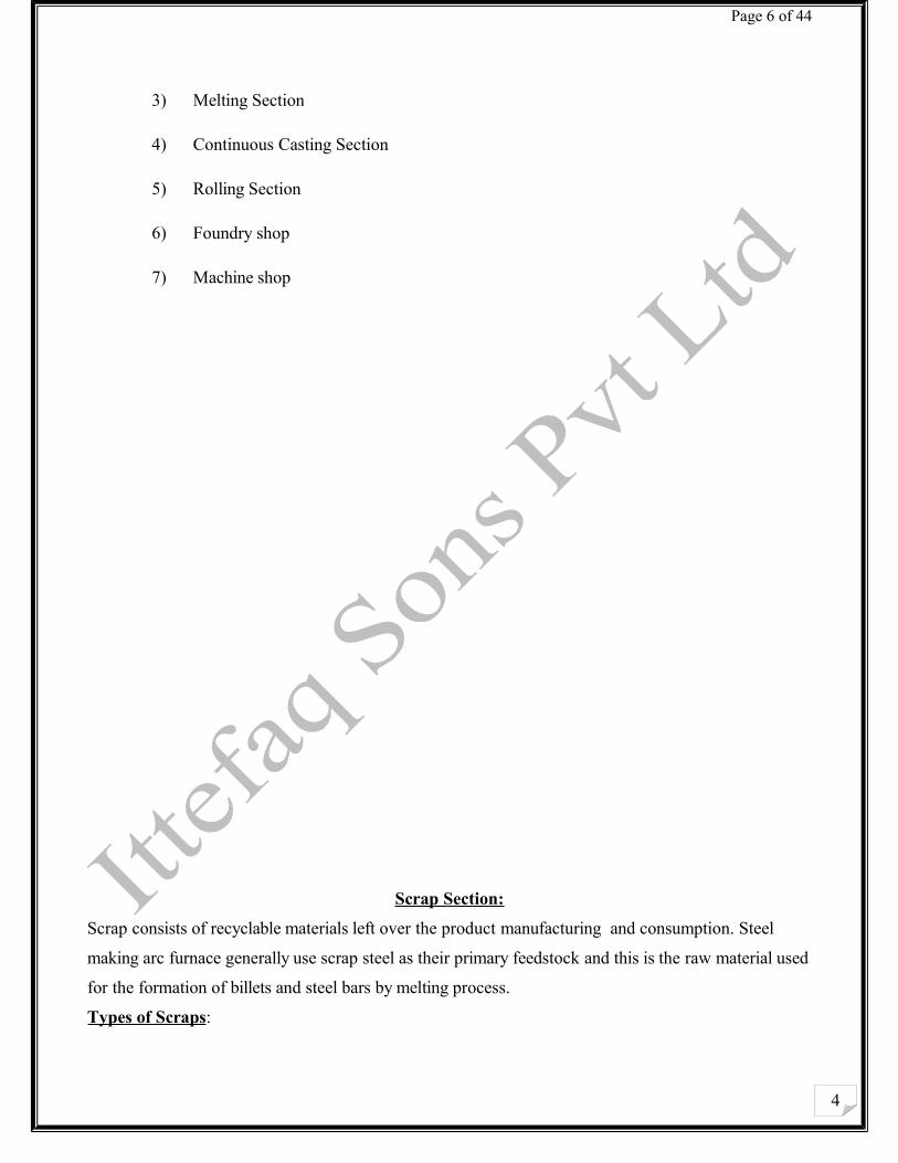
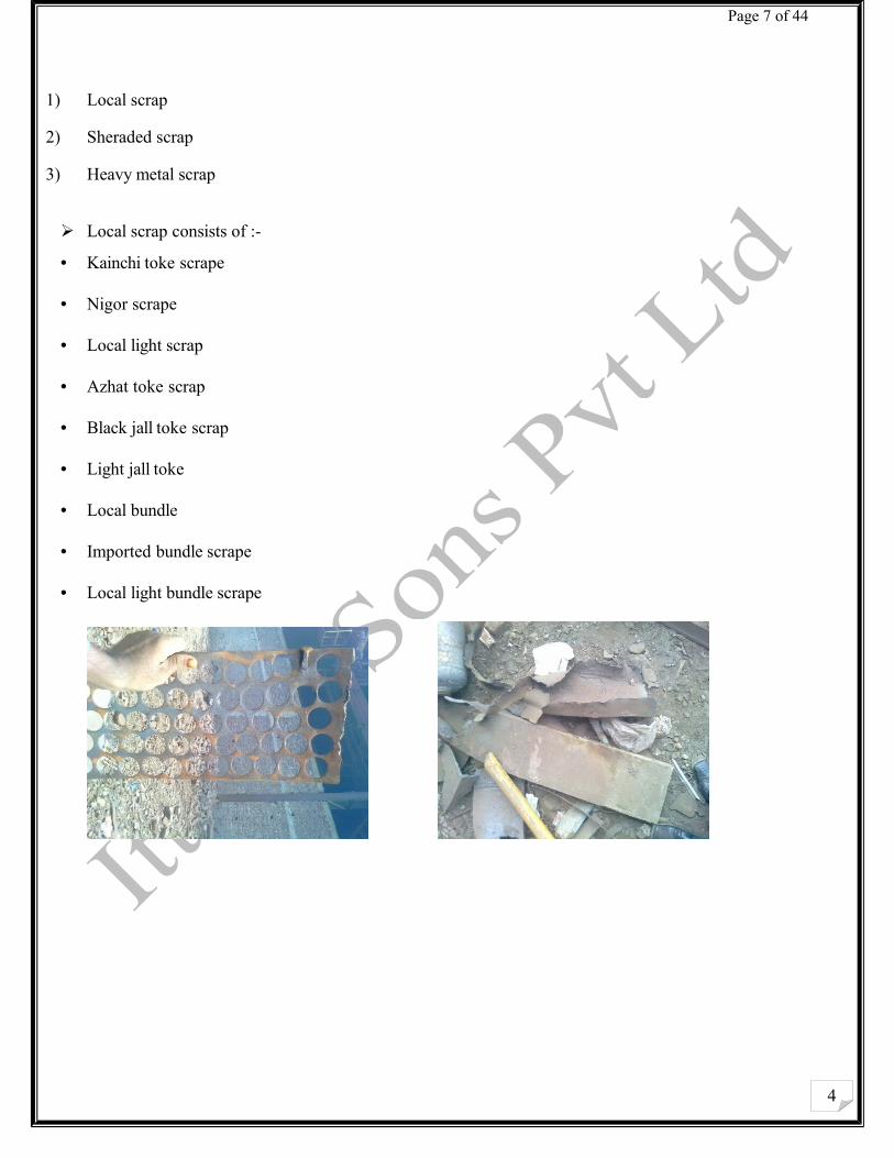
2) Sheraded scrap
3) Heavy metal scrap
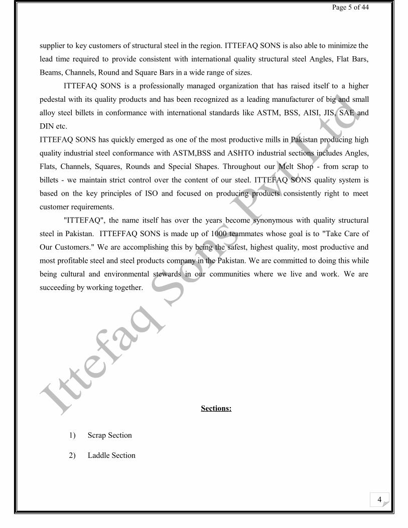
Local scrap consists of :-
• Kainchi toke scrape
• Nigor scrape
• Local light scrap
• Azhat toke scrap
• Black jall toke scrap
• Light jall toke
• Local bundle
• Imported bundle scrape
• Local light bundle scrape
4
Page 8 of 44
Sheraded scrap contain Alumanium ,Copper,Carbon, brass and low alloy steel.
Requirements:Scrape should be less amount of Carbon and Sulphur so the local scrap is preferable.
Supplier:Uk,USA,UAE by NBP,HBL & KASB BANK etc.
Charactaristics of Scrap: Scrape should be easily to handle
Easy charging
Permeability should be good.
Scrap should be in small size
Scrap should be without moisture content.
4
Page 9 of 44
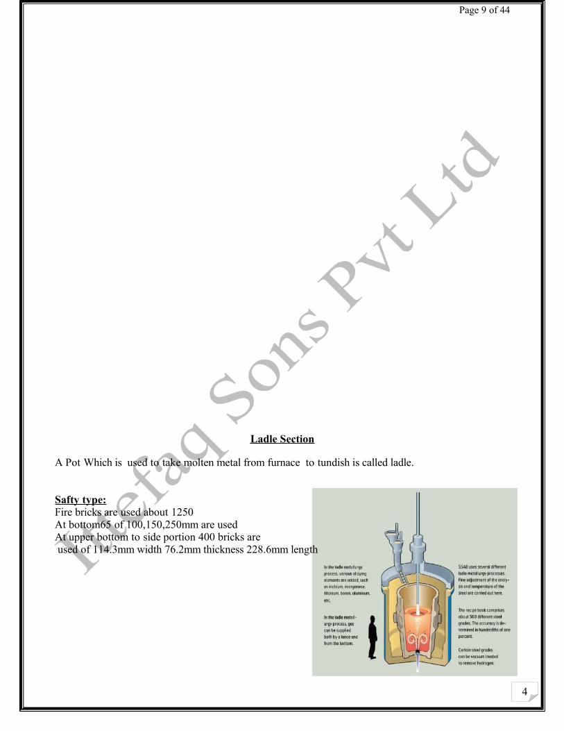
Ladle Section
A Pot Which is used to take molten metal from furnace to tundish is called ladle.
Safty type:Fire bricks are used about 1250At bottom65 of 100,150,250mm are usedAt upper bottom to side portion 400 bricks are used of 114.3mm width 76.2mm thickness 228.6mm length
4
Page 10 of 44
Taper type:90,110,150,250mm0in circle
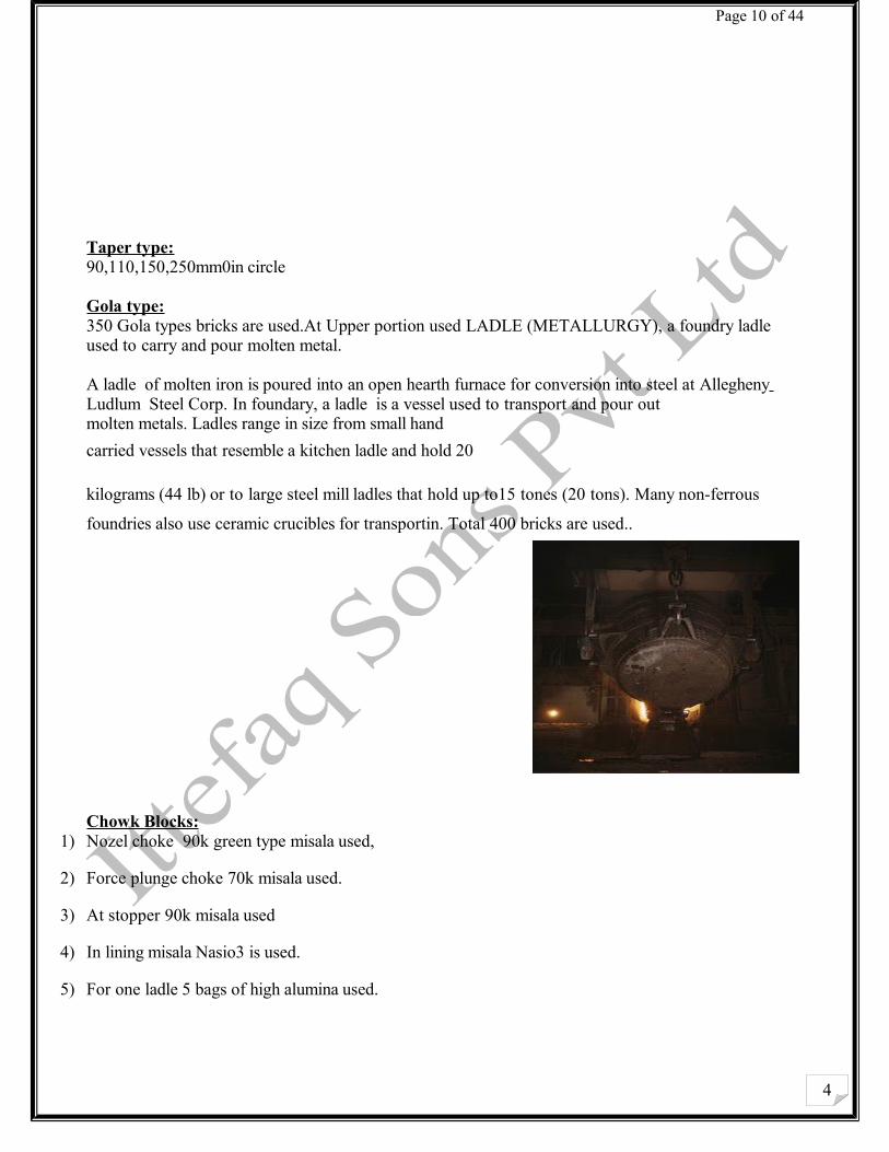
Gola type:350 Gola types bricks are used.At Upper portion used LADLE (METALLURGY), a foundry ladle used to carry and pour molten metal.
A ladle of molten iron is poured into an open hearth furnace for conversion into steel at Allegheny Ludlum Steel Corp. In foundary, a ladle is a vessel used to transport and pour out molten metals. Ladles range in size from small hand
carried vessels that resemble a kitchen ladle and hold 20
kilograms (44 lb) or to large steel mill ladles that hold up to15 tones (20 tons). Many non-ferrous
foundries also use ceramic crucibles for transportin. Total 400 bricks are used..
Chowk Blocks:1) Nozel choke 90k green type misala used,
2) Force plunge choke 70k misala used.
3) At stopper 90k misala used
4) In lining misala Nasio3 is used.
5) For one ladle 5 bags of high alumina used.
4
Page 11 of 44
6) For binding the bricks fire clay is used.
7) For pipe setting in nozzle white heats bags are used
Types Of ladle:
The basic term is often pre-fixed to define the actual purpose of the ladle. The basic ladle design can therefore include many variations that improve the usage of the ladle for specific tasks. For example:
1) Casting ladle:
A ladle used to pour molten metal into moulds to produce the casting.
2) Transfer ladle:
A ladle used to transfer a large amount of molten metal from one process to another. Typically a transfer ladle will be used to transfer molten metal from a primary melting furnace to either an holding furnace or an auto-pour unit.
3) Treatment ladle:
A ladle used for a process to take place within the ladle to change some aspect of the molten metal. A typical example being to convert cast iron to ductile iron by the addition of various elements into the ladle.
Unless the ladle is to be used with alloys that have very low temperature melting point, the ladle is also fitted with a refractory lining. It is the refractory lining that stops the steel vessel from suffering damage when the ladle is used to transport metals with high melting temperatures that, if the molten metal came in direct contact with the ladle shell, would rapidly melt through the shell. Refractory lining materials come in many forms and the right choice very much depends on each foundry's working practices. Traditionally ladles used to be lined using pre-cast firebricks however refractory concretes have tended to supersede these in many countries.
Foundry ladles are normally rated by their working capacity rather than by their physical size. Hand-held ladles are typically known as handshank ladles and are fitted with a long handle to keep the heat of the metal away from the person holding it. Their capacity is limited to what a man can safely handle. Larger ladles are usually referred to as geared crane ladles. Their capacity is usually determined by the ladle function. Small hand-held ladles might also be crucibles that are fitted with carrying devices. However, in most foundries, the foundry ladle refers to a steel vessel that has a lifting bail fitted so that the vessel can be carried by an overhead crane or monorail system and is also fitted with a mechanical means for rotating the vessel, usually in the form of a gearbox. The gearbox can either be manually operated or powered operation. (See the paragraph below for further details).
For the transportation of very large volumes of molten metal, such as in steel mills the ladle can run on wheels, a purpose-built carrying car or be slung from an overhead crane and will be tilted using a second overhead lifting device.
4
Page 12 of 44
The most common shape for a ladle is a vertical cone, but other shapes are possible. Having a tapered cone as the shell adds strength and rigidity to the shell. Having the taper also helps when it comes time to remove the refractory lining. However straight sided shells are also fabricated as are other shapes.
4
Page 13 of 44
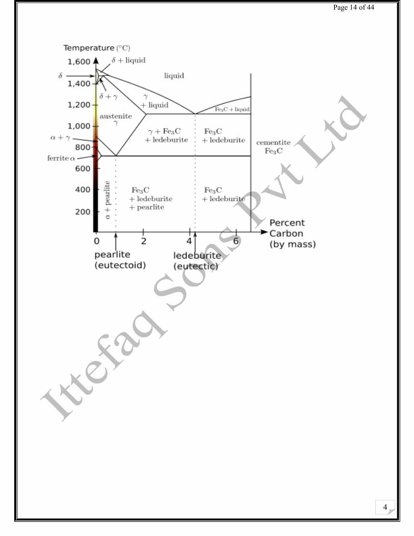
Melting Section:
Steel is an alloy that consists mostly of iron and has a carbon content between 0.2% and 2.1%
by weight, depending on the grade. Carbon is the most common alloying material for iron, but various
other alloying elements are used, such as manganese, chromium, vanadium, and tungsten. Carbon and
other elements act as a hardening agent, preventing dislocations in the iron atom crystal lattice from
sliding past one another. Varying the amount of alloying elements and the form of their presence in the
steel (solute elements, precipitated phase) controls qualities such as the hardness, ductility, and tensile
strength of the resulting steel. Steel with increased carbon content can be made harder and stronger
than iron, but such steel is also less ductile than iron.
4
Page 15 of 44
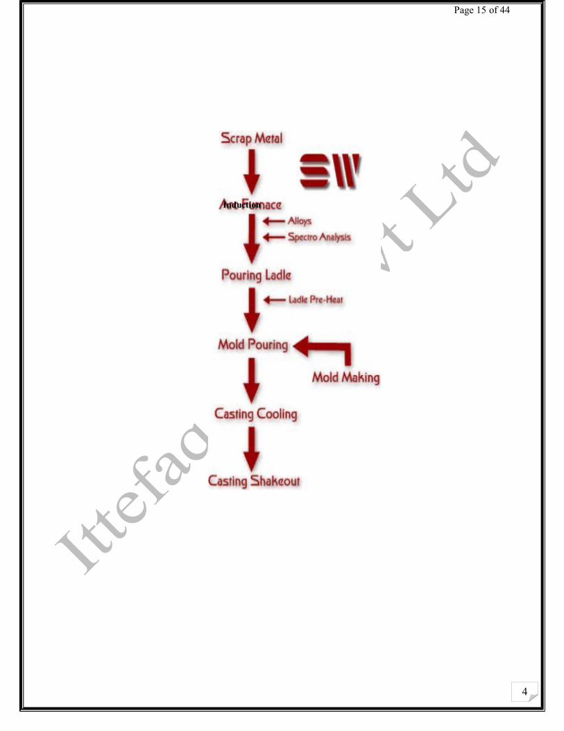
Induction
4
Page 16 of 44
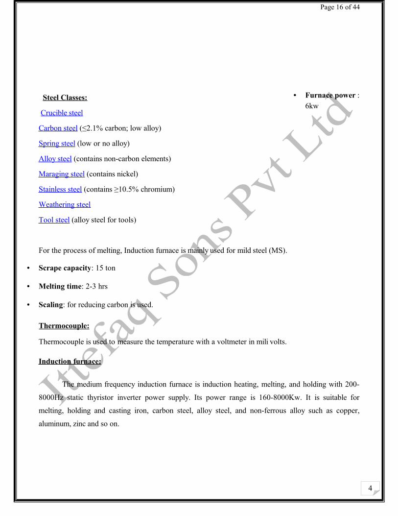
• Furnace power : 6kw
• Scrape capacity: 15 ton
• Melting time: 2-3 hrs
• Scaling: for reducing carbon is used.
Thermocouple:
Thermocouple is used to measure the temperature with a voltmeter in mili volts.
I nduction furnace:
The medium frequency induction furnace is induction heating, melting, and holding with 200-
8000Hz static thyristor inverter power supply. Its power range is 160-8000Kw. It is suitable for
melting, holding and casting iron, carbon steel, alloy steel, and non-ferrous alloy such as copper,
aluminum, zinc and so on.
Steel Classes:
Crucible steel
Carbon steel (≤2.1% carbon; low alloy)
Spring steel (low or no alloy)
Alloy steel (contains non-carbon elements)
Maraging steel (contains nickel)
Stainless steel (contains ≥10.5% chromium)
Weathering steel
Tool steel (alloy steel for tools)
For the process of melting, Induction furnace is mainly used for mild steel (MS).
4
Page 17 of 44
Induction furnace characteristics are as follows:-
(1) less volume, lighter weight, high efficiency and less power consumption.
(2) Lower temperature, less dust around the furnace.
(3) Simple operation, reliable and stable melting.
(4) Uniform temperature, less burning loss, uniform metal composition.
(5) Rapidly raise and easily control the heating temperature and higher production efficiency.
(6) High utilization rate and convenient replacement with various kinds of metals.
4
Page 18 of 44
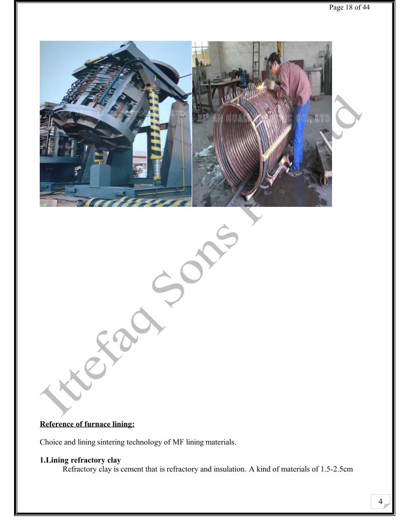
Reference of furnace lining:
Choice and lining sintering technology of MF lining materials.
1.Lining refractory clay Refractory clay is cement that is refractory and insulation. A kind of materials of 1.5-2.5cm
4
Page 19 of 44
thickness that protects induction coils and improves the machinery intensity of coils is coated in the inner wall of induction coil, meanwhile, which can make lining swell when hot and shrink when cold in the direction of uprightness. At present, domestic refractory clay can endure the high temperature of
1800℃ for half an hour and can prevent earth leakage effectively.
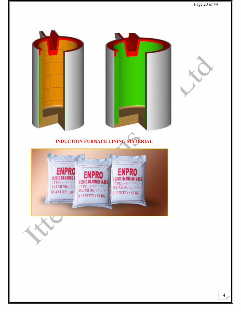
2. Choice of lining materials( crucible)① Lining materials There are 3 kinds of MF crucible furnace:
1. Alkaline: Alkaline crucible is mainly made from magnesia
2. Acidic: Acidic crucible only from SiO2
3. Neutral crucible: Neutral crucible only from Al2O3 and MgO•Al2O3 compound oxide and graphite
and so on
.Induction furnace crucible has the following features:
(1) Higher refractory function. Requirement for melting steel crucible is 1700oC and melting iron is
1500oC-1600oC;
(2) Steady chemical quality. Crucible product endure melted slag and steel liquid corrosion;
(3) A fine shockproof and high temperature intensity.
(4) With insulation function;
(5) Weaker heat conduction;
(6)smaller cost and no pollution
The common-used refractory materials that crucible is made from has 3 kinds: magnesium sand,
magnalium spinel and quartz sand and now the introduction is as follows:
magnalium spinel is a kind of manual synthetically refractory, theory component
Is (Al2O3)=71.5%,ω(MgO2)=28.5%;melting point is 2135℃,refractory degree is 1900℃,
4
Page 20 of 44
INDUCTION FURNACE LINING MATERIAL
4
Page 21 of 44
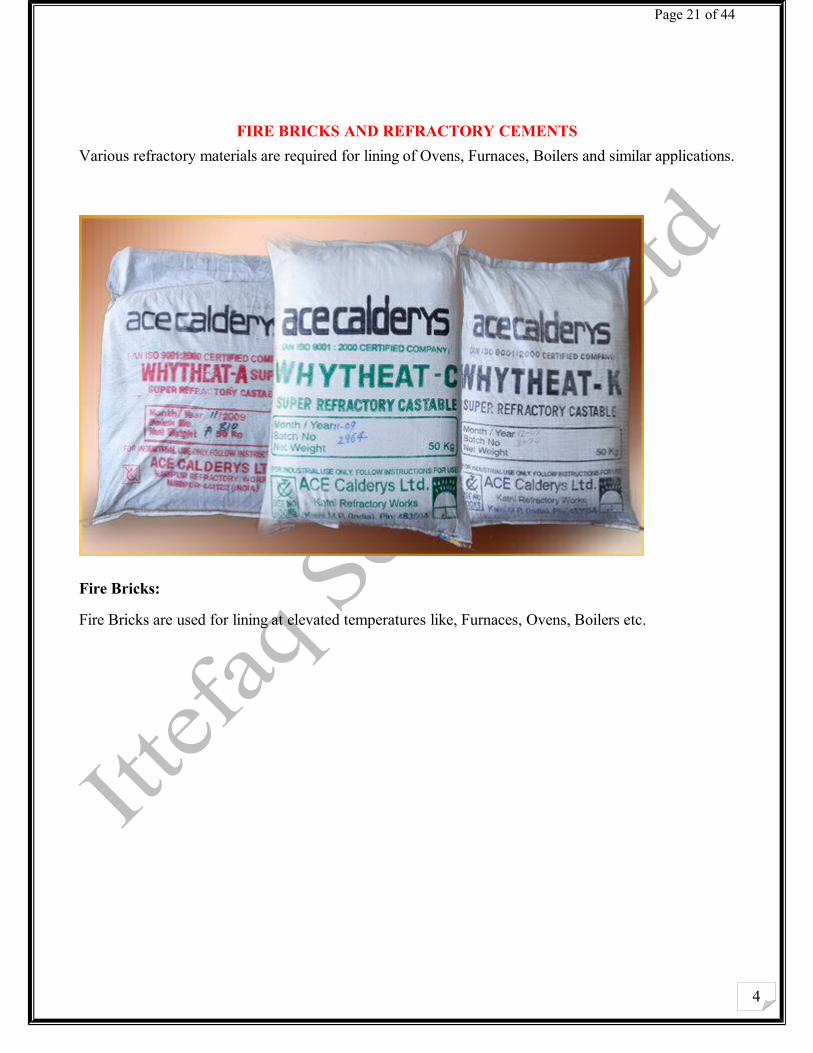
FIRE BRICKS AND REFRACTORY CEMENTS
Various refractory materials are required for lining of Ovens, Furnaces, Boilers and similar applications.
Fire Bricks:
Fire Bricks are used for lining at elevated temperatures like, Furnaces, Ovens, Boilers etc.
4
Page 22 of 44
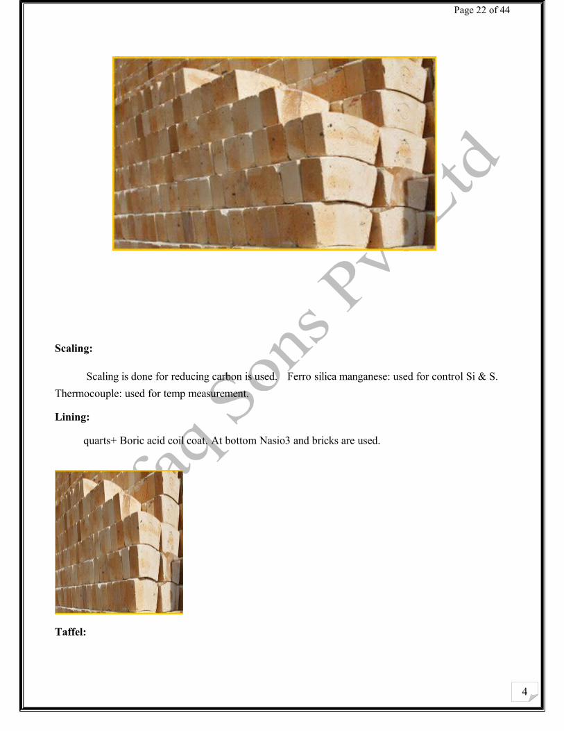
Scaling:
Scaling is done for reducing carbon is used. Ferro silica manganese: used for control Si & S.
Thermocouple: used for temp measurement.
Lining:
quarts+ Boric acid coil coat. At bottom Nasio3 and bricks are used.
Taffel:
4
Page 23 of 44
Nasio3 used for taffel making. Coil & coil is also used. Shell: is put in induction furnace An intina is used at bottom and a wire is used attach with this antina and grounded for prevention of shock. Alloying Elements: Al, ferrosilica and silica manganese. Boiling accur due to CO2 formation and for decreasing oxides Al is used. Grades: Three grades are used.
1. Grade 60 with yield 6000psi
2. Grade 40 with yield 4000psi
3. TMT (thermo mechanical treatment)
Mild steel composition:
C .18-.22 Si .15-.35, P .05, S .05 , Mn 0.75-0.8• Voltage 3000-3600volts
• Current 2240Amp
• Power 6000-6200kw
• Electrotherm from India
• Frequency 50Hz
• If more the core less frequency is required and vice versa.
• Industrial power factor 0.8.
Working principle of induction furnace:
Induction furnace has the same principle as a transformer. A high- frequency current is passed through a water-cooled coil which acts as the primary coil of a transformer. The charge i.e. steel scrap or other conductive metal, acts as the secondary coil of a transformer. The high-frequency alternating current passing through the primary coil generates a magnetic flux which cuts the secondary coil i.e. the metallic charge and induces an electromotive force, emf, in the charge and the charge gets heated up. When the temperature rises above the melting point of the metallic charge, it changes to liquid phase .
4
Page 24 of 44
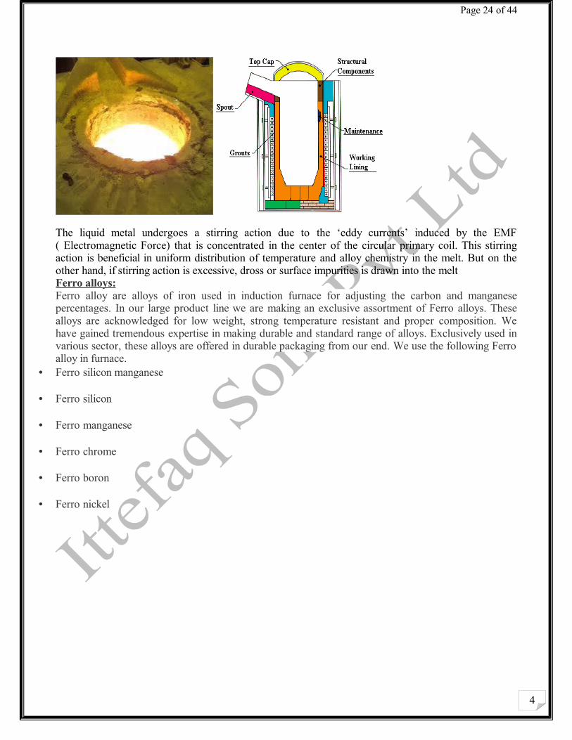
The liquid metal undergoes a stirring action due to the ‘eddy currents’ induced by the EMF ( Electromagnetic Force) that is concentrated in the center of the circular primary coil. This stirring action is beneficial in uniform distribution of temperature and alloy chemistry in the melt. But on the other hand, if stirring action is excessive, dross or surface impurities is drawn into the meltFerro alloys:Ferro alloy are alloys of iron used in induction furnace for adjusting the carbon and manganese percentages. In our large product line we are making an exclusive assortment of Ferro alloys. These alloys are acknowledged for low weight, strong temperature resistant and proper composition. We have gained tremendous expertise in making durable and standard range of alloys. Exclusively used in various sector, these alloys are offered in durable packaging from our end. We use the following Ferro alloy in furnace.
• Ferro silicon manganese
• Ferro silicon
• Ferro manganese
• Ferro chrome
• Ferro boron
• Ferro nickel
4
Page 25 of 44
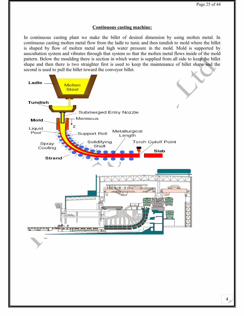
Continuous casting machine:
In continuous casting plant we make the billet of desired dimension by using molten metal. In continuous casting molten metal flow from the ladle to tunic and then tundish to mold where the billet is shaped by flow of molten metal and high water pressure in the mold. Mold is supported by auscultation system and vibrates through that system so that the molten metal flows inside of the mold pattern. Below the moulding there is section in which water is supplied from all side to keep the billet shape and then there is two straighter first is used to keep the maintenance of billet shape and the second is used to pull the billet toward the conveyor billet.
4
Page 26 of 44
What is Billet?
Billet is the solid form of liquid metal given a shape in continuous casting plant (CCM) provided as a raw material to produce different sizes of MS DEFORMED BARS, ANGLES, CHANNELS and other steel products in rolling mill.
Production Procedure of Billets
Temperature measure by the pyrometer again. 1585 to 1610°c (depend on composition of steel grade) should be the appropriate temperature to send the ladle to CCM for continuous casting.
From ladle the steel poured through a tundish into a water cooled copper mould. The bottom of this mould is sealed in the beginning by means of a dummy billet. As soon as the mould full, the dummy billet is withdrawn and as the casting proceeds, the desired height of liquid metal in the mould is maintained by adjusting the pouring speed and rate of with drawl.
The billet coming out of the bottom of the mould, is passed through another cooling chamber, which is sprayed with water to aid in complete solidification of steel. The billet then passes through the with drawl rolls and the continuously cast billet is then cut into desired length.
An external inspection and chemical analysis taken place by our quality department soon after the billets are somewhat cooling down. if no obvious defects are apparent and the chemical analysis establish the desire grade, heat number and suitable bar size marked on billets and cut into length for rolling.
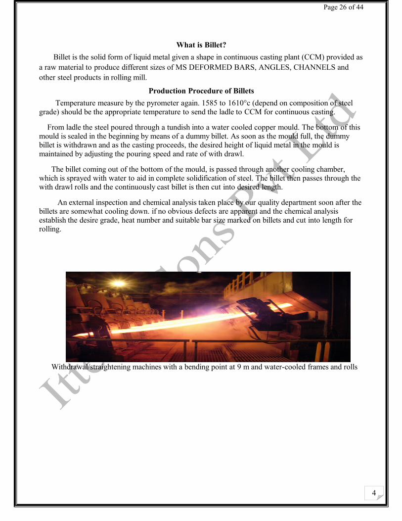
Withdrawal/straightening machines with a bending point at 9 m and water-cooled frames and rolls
4
Page 27 of 44
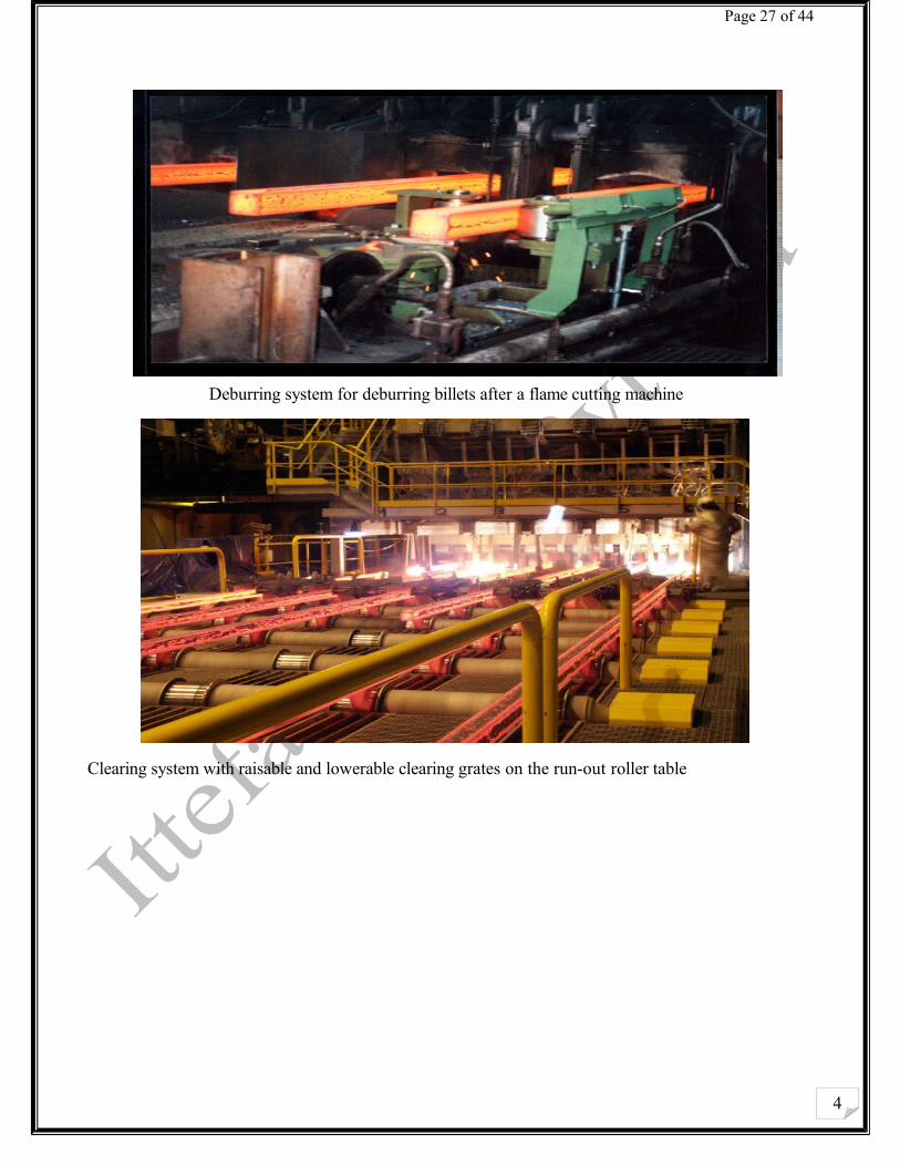
Deburring system for deburring billets after a flame cutting machine
Clearing system with raisable and lowerable clearing grates on the run-out roller table

4
Page 28 of 44
Rolling Mill Section
Pre-Heating Furnace: Before steel bar formation billets are preheated to be easily deformation this process is called pre-
heating.
Temperature required for pre-heating is 1200-1250 C.
Billets quantity in furnace is 230.
7000-8000 Bricks are used at bottom and side and at upper side Foam bricks are used.
8 Burner are used for burning of furnace with oil and gas.
Length is 90 Feet and width 16 feet.
Hydraullic press is used for pressing the billets into the furnace.
Pusher:
Used to push the billets into the rolling section.
Burner Types:1. Oil furnace Type
2. Gas usual Methane.
3. Blower (Air)
Rolling Section: First of all billets entered in rough stand where three rolls are used two of them moves clock wise
upper and lower and the central one moves anti clock wise.
Billets forward and back distance between the rolls is 8 mm by which length of billets increased, After rough stand billets length becomes 13-14 meters with 54 mm.
Billets total weight 280kg.
Original length of billet is 3450 mm.
4
Page 29 of 44
After rough stand billets shapes change into round and enter into C1 oval shape of 65*29 mm.
At C2 shape change 36*37 mm. The distance between oval and round is small.
At C3 19*46 mm.
At C4 round shape is formed and is of 25*26 mm dimensions.
C5 oval shaped formed 14*36 mm.
At C6 round shaped formed 19*20 mm.
Pinch rolls draws the steel bars towards the next pinch roll, and make equally round.
Fly wheel speed 750 rpm.
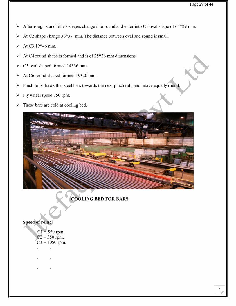
These bars are cold at cooling bed.
COOLING BED FOR BARS
Speed of rolls:
C1 = 550 rpm.C2 = 550 rpm.C3 = 1050 rpm.. .
. .
. .
4
Page 30 of 44
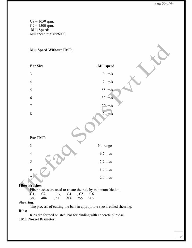
C8 = 1050 rpm.C9 = 1500 rpm. Mill Speed:Mill speed = πDN/6000.
Mill Speed Without TMT:
Bar Size Mill speed
3 9 m/s
4 7 m/s
5 55 m/s
6 32 m/s
7 22 m/s
8 2 m/s
For TMT:
3 No range
4 6.7 m/s
5 5.2 m/s
6 3.0 m/s
7 2.0 m/s
Fiber Brushes:Fiber bushes are used to rotate the role by minimum friction.C1, C2, C3, C4 , C5, C6383 486 831 914 755 905
Shearing:The process of cutting the bars in appropriate size is called shearing.
Ribs:Ribs are formed on steel bar for binding with concrete purpose.
TMT Nozzel Diameter:
4
Page 31 of 44
1. 10-20 mm dia of bar.
2. 25-32 mm dia of bar.
3. 32-40 mm dia of bar.
Types of rolling :
There are 2 types:
1. Cold rolling
2. Hot rolling
Hot Rolling: The distinctive mark of hot rolling is not a crystallized structure, but the simultaneous occurrence of dislocation propagation and softening processes, with or without recrystallization during rolling. The dominant mechanism depends on temperature and grain size. In general, the recrystallized structure becomes finer with lower deformation temperature and faster cooling rates and material of superior properties are obtained by controlling the finishing temperature.Hot rolling offers several advantages
1) Flow stresses are low, hence forces and power requirements are relatively low, and even very large workpieces can be deformed with equipment of reasonable size.
2) Ductility is high; hence large deformations can be taken (in excess of 99% reduction).3) Complex part shapes can be generated.
Cold rolling: Cold rolling, in the everyday sense, means rolling at room temperature, although the work of deformation can raise temperatures to 100-200°C. Cold rolling usually follows hot rolling. A material subjected to cold rolling strain hardness considerably. Dislocation density increases, and when a tension test is performed on this strain-hardened material, a higher stress will be needed to initiate and maintain plastic deformation; thus, the yield stress increases. However, the ductility of the material – as expressed by total elongation and reduction of area – drops because of the higher initial dislocation density. Similarly, strength coefficient rises and strain-hardening exponent drops. Crystals (grains) become elongated in the direction of major deformation .
Cold rolling has several advantages:1) In the absence of cooling and oxidation, tighter tolerances and better surface finish can be
obtained.2) Thinner walls are possible.3) The final properties of the workpiece can be closely controlled and, if desired, the high
strength obtained during cold rolling can be retained or, if high ductility is needed, grain size can be controlled before annealing.
4) Lubrication is, in general, easier.
What is TMT…?
4
Page 32 of 44
TMT means thermo mechanical treatment.
It is new generation high strength steel having superior properties such as weld ability,strength, ductility and tensility which meets the highest international quality standards.
Mechanical Testing Lab:
Yield Strength
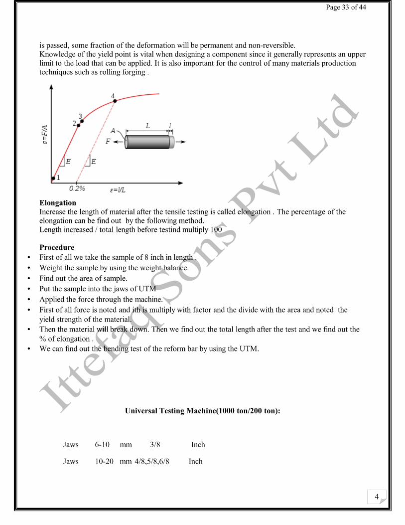
The yield strength or yield point of a material is defined in engineering and material science as the stress at which a material deform plastically. Prior to the yield point the material will deform elastically and will return to its original shape when the applied stress is removed. Once the yield point
4
Page 33 of 44
is passed, some fraction of the deformation will be permanent and non-reversible.Knowledge of the yield point is vital when designing a component since it generally represents an upper limit to the load that can be applied. It is also important for the control of many materials production techniques such as rolling forging .
Elongation Increase the length of material after the tensile testing is called elongation . The percentage of the elongation can be find out by the following method. Length increased / total length before testind multiply 100
Procedure • First of all we take the sample of 8 inch in length .• Weight the sample by using the weight balance. • Find out the area of sample.• Put the sample into the jaws of UTM • Applied the force through the machine. • First of all force is noted and ith is multiply with factor and the divide with the area and noted the
yield strength of the material.• Then the material will break down. Then we find out the total length after the test and we find out the
% of elongation . • We can find out the bending test of the reform bar by using the UTM.
Universal Testing Machine(1000 ton/200 ton):
Jaws 6-10 mm 3/8 Inch
Jaws 10-20 mm 4/8,5/8,6/8 Inch
4
Page 34 of 44
Jaws 320-40 mm 7/8,11/8 Inch
Weight/ Length * 304.8= Weight in gram / Feet
W(lbs) = Weight in gram* 2.2046
Area = Weight (lbs) / 3.4
Area(mm) = Area(lbs) / 1000
Pin Diameter:
3, 4, 5 (sotar) = 3.5 mm
6, 7, 8 = 5 mm
9, 10, 11 = 7 mm
Chemical Lab:
In chemical lab chemical composition can be find out by using the different techniques. Checking of water is also done in chemical lab, chemical lab contains.
• C and S analyzer • oven • muffle Furnace• Water Distillation • Spectrometer for Silicon, copper and Nickel
1- Carbon and Sulfur Analyzer
The techniques is used to find out the composition of C and Si, it contains • Electric tube furnace
4
Page 35 of 44
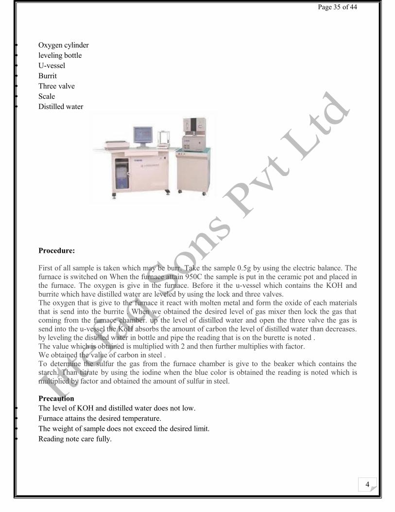
• Oxygen cylinder• leveling bottle• U-vessel • Burrit • Three valve• Scale• Distilled water
Procedure:
First of all sample is taken which may be burr. Take the sample 0.5g by using the electric balance. The furnace is switched on When the furnace attain 950C the sample is put in the ceramic pot and placed in the furnace. The oxygen is give in the furnace. Before it the u-vessel which contains the KOH and burrite which have distilled water are leveled by using the lock and three valves.The oxygen that is give to the furnace it react with molten metal and form the oxide of each materials that is send into the burrite . When we obtained the desired level of gas mixer then lock the gas that coming from the furnace chamber. up the level of distilled water and open the three valve the gas is send into the u-vessel the KoH absorbs the amount of carbon the level of distilled water than decreases. by leveling the distilled water in bottle and pipe the reading that is on the burette is noted .The value which is obtained is multiplied with 2 and then further multiplies with factor. We obtained the value of carbon in steel . To determine the sulfur the gas from the furnace chamber is give to the beaker which contains the starch. Than titrate by using the iodine when the blue color is obtained the reading is noted which is multiplied by factor and obtained the amount of sulfur in steel.
Precaution • The level of KOH and distilled water does not low.• Furnace attains the desired temperature.• The weight of sample does not exceed the desired limit.• Reading note care fully.
4
Page 36 of 44
2-Oven It is used to remove the moisture from the material .
3-Muffle furnaceIt is used when heating is done in the vacuum . we obtain 1100 C in the muffle furnace.
4-Water Distillation Water distillation can be done by the distillation plant . The distillation water is used in chemicals and in experiments.
Water Treatment
1-Calcium Hardness in water (CaH) Definition
The concentration of calcium salts in the water is known as calcium hardness and is expressed in ppm as CaCo3.2-Total Hardness of Water
The combined concentration of calcium and magnesium salts in the water is known as total hardness and is expressed in ppm as CaCo3.3-TDS
All dissolved material in water are known as total dissolved solids TDS.4-Phenolphthalein Alkalinity in Water P-Alkalinity
Alkalinity due to half of carbonates and all hydrates presents in the water , expressed as ppm (mg/Litre ) in terms of CaCo3. It exists above the Ph 8.2 and is defined as the alkalinity which reacts with acid as the ph of sample is reduced to 8.2 5-Chlorides in Water (CI)
The chloride ion is formed when the emement chloride picks up one electron to form an anion 9 negatively-charged ion) . The salts of hyrochloric acid HCl contain chloride ions and can also be called chlorides . An example is table salt. Which is sodium chloride with the chemical formula NaCl. In water it dissolves into form of ions.
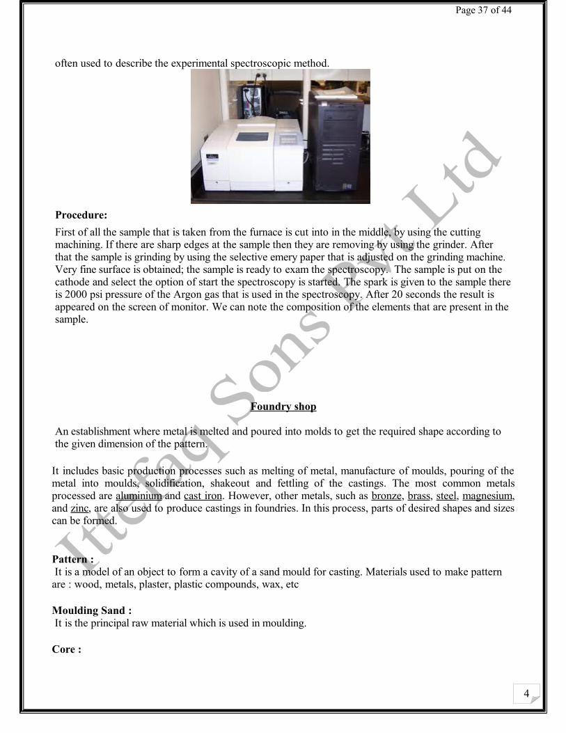
Spectroscopy
Spectroscopy is the study of interaction between the metal and radition energy . atom of the different element have a different spectre . There for atomic spectroscopy allow for the identification and quantificaion of the sample elemintal composition.Spectroscopy used to reffer to measurement of radiation intensity as the function of wavelength are
4
Page 37 of 44
often used to describe the experimental spectroscopic method.
Procedure:
First of all the sample that is taken from the furnace is cut into in the middle, by using the cutting machining. If there are sharp edges at the sample then they are removing by using the grinder. After that the sample is grinding by using the selective emery paper that is adjusted on the grinding machine. Very fine surface is obtained; the sample is ready to exam the spectroscopy. The sample is put on the cathode and select the option of start the spectroscopy is started. The spark is given to the sample there is 2000 psi pressure of the Argon gas that is used in the spectroscopy. After 20 seconds the result is appeared on the screen of monitor. We can note the composition of the elements that are present in the sample.
Foundry shop
An establishment where metal is melted and poured into molds to get the required shape according to the given dimension of the pattern.
It includes basic production processes such as melting of metal, manufacture of moulds, pouring of the metal into moulds, solidification, shakeout and fettling of the castings. The most common metals processed are aluminium and cast iron. However, other metals, such as bronze, brass, steel, magnesium, and zinc, are also used to produce castings in foundries. In this process, parts of desired shapes and sizes can be formed.
Pattern : It is a model of an object to form a cavity of a sand mould for casting. Materials used to make pattern are : wood, metals, plaster, plastic compounds, wax, etc
Moulding Sand : It is the principal raw material which is used in moulding.
Core :
4
Page 38 of 44
The portion of the mould which forms the hollow interior of the castings or hole through the castings. Gates and RisersThere is almost an endless variety of gates and risers and combinations of them. It is impossible to do anymore than cover the reasons we use certain combinations.The basic parts of a gating system are the pouring basin, the sprue, the runner and the ingates. The object of any gating system is to allow the mold to be filled as rapidly as possible with a minimum amount of turbulence and to provide sufficient hot metal to feed the casting during solidification to prevent shrinkage defects. As a casting will solidify from the thinnest section toward the heavier section and in doing so draws liquid metalfrom the heavy section, therefore the heavy section must be supplied with a riser or reservoir of hot metal, or it would shrink as it gives up its liquid metal to feed the solidifying thin section. Consequently, we must gate into the heavy section and provide it with feed metalssss
Furnaces :
In itfaq steel industry foundry following furnaces are being utilised
Annealing furnace
Rotary furnace
Pit furnace
Crucible furnace
Annealing furnace:
Annealing furnace is used for the cooling of different parts in the foundry shop
Rotary furnace:
Rotary furnace is used for the production of molten metal. The scrape use in rotary furnace is pig iron and cast iron scrape.
Pit furnace:
Pit furnace used for aluminium, brass bronze and cu melting
Sand used in foundry shop: Green sand is the only sand in its natural state and is quite moist. It has excellent property of conformability because of its dampness. The mould should be properly vented which is made of green sand.
Dry Sand: The green sand is called dry sand when moisture is removed from it. Dry sand is used for large size castings.
Loam Sand: The mixture of clay and fireclay, sand with water obtains a thin plastic paste that is plastered on moulds with soft bricks and hardness on drying.
4
Page 39 of 44
Facing Sand: Applied on the face of the mould and comes in contact with the molten metal.
Backing Sand: The used sand which is prepared from mould and is used time and again.
Parting Sand: It is fine sharp dry sand which is used to keep the green sand from sticking to the pattern and also to keep the boxes separated.
Hard Ramming: This method has low initial cost and it is laborious and slow.
Squeezing: It is suitable for relatively small work and best for shallow flakes.
Sand Slingers: The process which is fast and produces uniform ramming. It has a high initial cost.
Power Press Operations: The operation in which shearing is the most common action.
Metal Blanking: This is the process of punching, cutting or shearing a piece out of stock to a predetermined shape. In this process the black should be flat and thus punch is made flat and shear provided on the die.
Hole Punching: In this process the scrap is punched out, the die is kept flat and shear provided on punch. For clear cut and durability, clearance between the punch and die is required.
Metal Bending: Performed in a variety of presses, brakes, forming rolls, roll straightness etc. Spring back may be compensated for by over bending due to the elasticity of the metal and amount of the bend.
Metal Drawing: In this process flat sheets or blanks are pulled or drawn in suitable containing tools through a die. In this process metal is drawn into cylindrical cup or rectangular or irregular shapes, deep or shallow. Griding:The final step in the process usually involves grinding, sanding, or machining the component in order to achieve the desired dimensional accuracies, physical shape and surface finish.Removing the remaining gate material, called a gate stub, is usually done using a grinder or sanding.
Machine shopPattern shop
4
Page 40 of 44
A pattern is a shaped form of wood or metal around which sand is packed in the mold. When the pattern is removed the resulting cavity is the exact shape of the object to be cast.The pattern must be designed to be easily removed without damage to the mold. It must be accurately dimensioned and durableenough for the use intended. Either one time use or production runs.
PATTERN MAKINGEach different item we wish to cast presents unique problems and requirements. In a large foundry there is a close relationship between the pattern maker and the molder. Each is aware of the capabilities and limitations of his own field.Throughout the industry, pattern making is a field and an art of it's own. The pattern maker is not a molder nor the molder a pattern maker. This is not to imply that the pattern maker cannot make a simple mold or the molder ma.ke a simple pattern but each may soon reach a point in the other's field beyond his own skill and experience.In the hobby or one man shop, however, pattern and mold making are so closely interrelated as to become almost one continuous operation. This chapter will acquaint you with some of thevarious types of patterns and their requirements.ShrinkageNow back to our simple disc pattern. If we wish the casting to come out as cast to the dimensions we show of 12 inches in diameter 1 inch thick, we must make the pattern larger and thicker than 12 inches x 1 inch to compensate for the amount that the metal will shrink when going from a liquid to a solid. This is called pattern shrinkage. This varies with each type of metal and the shape of thecasting.The added dimensions are incorporated into the pattern by the pattern maker by using what is called shrink rulers. These rulers are made of steel and the shrinkage is compensated for by having beenworked proportionately over its length. Thus a 3/16 inch shrink rule 12 inches long will be actually 12 3/16 inches long, but for all appearances will look like a standard rule. But, when layed out against standard ruler it win project 3/16 inch past the standard ruler. These rulers come in a large variety of shrinks. Generally the shrinkage allowance for brass is 3/16 inch per foot, % inch per foot for cast iron, % inch per foot for aluminum and % inch for steel. This would hold true for most small to medium work, for larger work the shrinkage allowance is less, in some cases 50 percent less. Where a small steel casting in steel would require % inch per foot shrinkage allowance, a very large steel casting might require only % inch per foot shrinkage allowance. So, from this we see that if we wish to casta bar in brass 1 foot long we must make the pattern 1 foot and 3/16 inches long to start with.
Lathe machine:
Working principal:The lathe is a machine tool which holds the workpiece between two rigid and strong supports called centers or in a chuck or face plate which revolves. The cutting tool is rigidly held and supported in a tool post which is fed against the revolving work. The normal cutting operations are performed with the cutting tool fed either parallel or at right angles to the axis of the work. The cutting tool may also be fed at an angle relative to the axis of work for machining tapers and angles.
4
Page 41 of 44
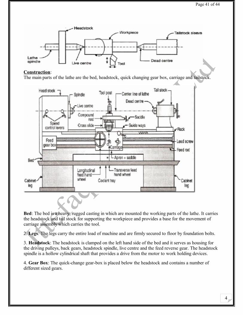
Construction: The main parts of the lathe are the bed, headstock, quick changing gear box, carriage and tailstock.
Bed: The bed is a heavy, rugged casting in which are mounted the working parts of the lathe. It carries the headstock and tail stock for supporting the workpiece and provides a base for the movement of carriage assembly which carries the tool.
2. Legs: The legs carry the entire load of machine and are firmly secured to floor by foundation bolts.
3. Headstock: The headstock is clamped on the left hand side of the bed and it serves as housing for the driving pulleys, back gears, headstock spindle, live centre and the feed reverse gear. The headstock spindle is a hollow cylindrical shaft that provides a drive from the motor to work holding devices.
4. Gear Box: The quick-change gear-box is placed below the headstock and contains a number of different sized gears.
4
Page 42 of 44
5. Carriage: The carriage is located between the headstock and tailstock and serves the purpose of supporting, guiding and feeding the tool against the job during operation. The main parts of carriage are:
a). The saddle is an H-shaped casting mounted on the top of lathe ways. It provides support to cross-slide, compound rest and tool post.
b). The cross slide is mounted on the top of saddle, and it provides a mounted or automatic cross movement for the cutting tool.
c). The compound rest is fitted on the top of cross slide and is used to support the tool post and the cutting tool.
d). The tool post is mounted on the compound rest, and it rigidly clamps the cutting tool or tool holder at the proper height relative to the work centre line.
e). The apron
is fastened to the saddle and it houses the gears, clutches and levers required to move the carriage or cross slide. The engagement of split nut lever and the automatic feed lever at the same time is prevented she carriage along the lathe bed.
6. Tailstock:
The tailstock is a movable casting located opposite the headstock on the ways of the bed. The tailstock can slide along the bed to accommodate different lengths of workpiece between the centers. A tailstock clamp is provided to lock the tailstock at any desired position. The tailstock spindle has an internal taper to hold the dead centre and the tapered shank tools such as reamers and drills.
LATHE OPERATIONS
The engine lathe is an accurate and versatile machine on which many operations can be performed. These operations are:
1. Plain Turning and Step Turning
2. Facing
3. Drilling
4. Boring
5. Knurling
6. Grooving
7. Threading
DRILLING MACHINE
4
Page 43 of 44
Introduction: The drilling machine or drill press is one of the most common and useful machine employed in industry for producing forming and finishing holes in a workpiece. The unit essentially consists of:
1. A spindle which turns the tool (called drill) which can be advanced in the workpiece either automatically or by hand.
2. A work table which holds the workpiece rigidly in position.
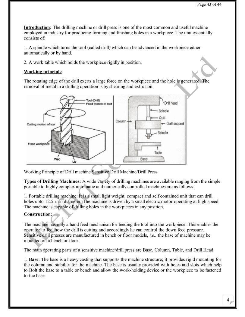
Working principle:
The rotating edge of the drill exerts a large force on the workpiece and the hole is generated. The removal of metal in a drilling operation is by shearing and extrusion.
Working Principle of Drill machine Sensitive Drill Machine/Drill Press
Types of Drilling Machines: A wide variety of drilling machines are available ranging from the simple portable to highly complex automatic and numerically controlled machines are as follows:
1. Portable drilling machine: It is a small light weight, compact and self contained unit that can drill holes upto 12.5 rnrn diameter. The machine is driven by a small electric motor operating at high speed. The machine is capable of drilling holes in the workpieces in any position.
Construction:
The machine has only a hand feed mechanism for feeding the tool into the workpiece. This enables the operator to feel how the drill is cutting and accordingly he can control the down feed pressure. Sensitive drill presses are manufactured in bench or floor models, i.e., the base of machine may be mounted on a bench or floor.
The main operating parts of a sensitive machine/drill press are Base, Column, Table, and Drill Head.
1. Base: The base is a heavy casting that supports the machine structure; it provides rigid mounting for the column and stability for the machine. The base is usually provided with holes and slots which help to Bolt the base to a table or bench and allow the work-holding device or the workpiece to be fastened to the base.
4
Page 44 of 44
2. Column: The column is a vertical post that Column holds the worktable and the head containing the driving mechanism. The column may be of round or box section.
3. Table: The table, either rectangular or round. Drill machine/press in shape supports the workpiece and is carried by the vertical column. The surface of the table is 90-degree to the column and it can be raised, lowered and swiveled around it. The table can be clamp/hold the required the workpiece. Slots are provided in most tables to allow the jigs, fixtures or large workpieces to be securely fixed directly to the table.
4. Drilling Head: The drilling head, mounted close to the top of the column, houses the driving arrangement and variable speed pulleys. These units transmit rotary motion at different speeds to the drill spindle. The hand feed lever is used to control the vertical movement of the spindle sleeve and the cutting tool.
The system is called the sensitive drilling machine/press as the operator is able to sense the progress of drill with hand-faced.
Shaper Machine:
Stroke 32 “, Bolts and trash plateWorking automatically and manually.
Planner Machine:
The difference between a shaper machine and planer machine is that in planner machine bed is moved having to and fro motion against the tool and cutting is done. On planner trash plate machining and finishing is done. Planner machine consists of three machines:
1) Shaper Machine2) Drilling Machine3) Milling Machine