item# 891340 electric pipe cutting threader user’s manual · item# 891340 electric pipe cutting...
TRANSCRIPT

Item# 891340 Electric Pipe Cutting Threader
User’s Manual
Assembly and Operation Instructions MADE IN CHINA

For technical questions and replacement parts, please call 1-800-556-7885.
Thank you very much for choosing a NORTHERN TOOL & EQUIPMENT CO., Product! For future reference, please complete the owner’s record below:
Model: _______________ Purchase Date: _______________
Save the receipt, warranty and these instructions. It is important that you read the entire instruction sheet to become familiar with this product before you begin using it.
This machine is designed for certain applications only. Northern Tool & Equipment strongly recommends that this machine is not modified and/or used for any application other than that for which it was designed. If you have any questions relative to a particular application, DO NOT use the machine until you have first contacted Northern Tool & Equipment to determine if it can or should be performed on the product.
Before using the Electric Pipe Cutting Threader, please read the following instructions carefully.
Specifications
ITEM DESCRIPTION Pipe Capacity 1/2 to 2 inches NPT Rotation Threading Speed
~26 RPM
1/2 to 3/4 inch, 14 TPI; 1 to 2 inch, 11-1/2 TPI; Threading Die Sets All dies between HRC 54 to 58. Each die is numbered for position.
Chuck Capacity 2-3/8 inch maximum; manual opening Carriage Travel 5-5/8 inches Oiler Automatic, electric pump Switch Pushbutton On/Off Power Consumption
110 VAC @14.3 amps (starting), 7.8 amps (no load); 750 watts, single phase, 60 Hz;
Power Cord 54 inches, 18 gauge, 3-wire, U.L., with grounding plug Motor 1 HP, 3400 RPM, single speed drive Dimensions 25 (L) x 16 (W) x 17.5 (H) inches (with legs attached: 36 .(H) inches) Weight 200 lbs.
Page 1 of 12
Safety Warnings and Precautions WARNING: When using tool, basic safety precautions should always be followed to reduce the risk of personal injury and damage to equipment.
Read all instructions before using this tool!
1. Keep work area clean. Cluttered areas invite injuries.
2. Observe work area conditions. Do not use machines or power tools in damp or wet locations. Don’t expose to rain. Keep work area well lighted. Do not use electrically powered tools in the presence of flammable gases or liquids.
3. Keep children away. Children must never be allowed in the work area. Do not let them handle machines, tools, or extension cords.
4. Store idle equipment. When not in use, tools must be stored in a dry location to inhibit rust. Always lock up tools and keep out of reach of children.
5. Do not force tool. It will do the job better and more safely at the rate for which it was intended. Do not use inappropriate attachments in an attempt to exceed the tool capacity.
6. Use the right tool for the job. Do not attempt to force a small tool or attachment to do the work of a larger industrial tool. Do not use a tool for a purpose for which it was not intended.
7. Dress properly. Do not wear loose clothing or jewelry as they can be caught in moving parts. Protective, electrically non-conductive clothes and non-skid footwear are recommended when working. Wear restrictive hair covering to contain long hair.
8. Use eye and ear protection. Always wear ANSI approved impact safety goggles. Wear a full face shield if you are producing metal filings or wood chips. Wear an ANSI approved dust mask or respirator when working around metal, wood, and chemical dusts and mists.
9. Do not overreach. Keep proper footing and balance at all times. Do not reach over or across running machines.
10. Maintain tools with care. Keep tools sharp and clean for better and safer performance. Follow instructions for lubricating and changing accessories. Inspect tool cords periodically and, if damaged, have them repaired by an authorized technician. The handles must be kept clean, dry, and free from oil and grease at all times.
11. Disconnect power. Unplug machine when not in use.
12. Remove adjusting keys and wrenches. Check that keys and adjusting wrenches are removed from the tool or machine work surface before plugging it in.
Page 2 of 12
13. Avoid unintentional starting. Be sure the switch is in the Off position when not in use and before plugging in. 14. Stay alert. Watch what you are doing, use common sense. Do not operate any tool when you are tired.
15. Check for damaged parts. Before using any tool, any part that appears damaged should be carefully checked to determine that it will operate properly and perform its intended function. Check for alignment and binding of moving parts; any broken parts or mounting fixtures; and any other condition that may affect proper operation. Any part that is damaged should be properly repaired or replaced by a qualified technician. Do not use the tool if any switch does not turn On and Off properly.
16. Guard against electric shock. Prevent body contact with grounded surfaces such as pipes, radiators, ranges, and refrigerator enclosures.
17. Replacement parts and accessories. When servicing, use only identical replacement parts. Use of any other parts will void the warranty. Only use accessories intended for use with this tool.
18. Do not operate tool if under the influence of alcohol or drugs. Read warning labels on prescriptions to determine if your judgment or reflexes are impaired while taking drugs. If there is any doubt, do not operate the tool.
Unpacking When unpacking, check to make sure the following parts are included.
Cutting Oil (2.5 litres) Pouch with: 2 Sets of dies, 3 Hex Wrenches Machine Stand Legs (3) and 1 Screwdriver
Assembly
1. With the unit on its side, insert the four Machine Stand legs into the holes in the base.
2. Secure with lock bolts provided.
3. Hoist up the unit and place upright on its legs.
4. Please insert the pin into body (Part 1, pg.9) to assemble the cutter (Part 6, pg.12)
Page 3 of 12
Preparation for Pipe Threading Changing Dies
The pipe threader machine comes with three sets of dies. Each set is used to cut threads on a particular size of pipe as listed in the following table.
PIPE SIZE DIE SET 1/2 to 3/4 inch 1/2 to 3/4 inch, 14 threads per inch (TPI) 1 to 2 inch 1 to 2 inch, 11-1/2 TPI
1. Determine the size of the pipe to be threaded.
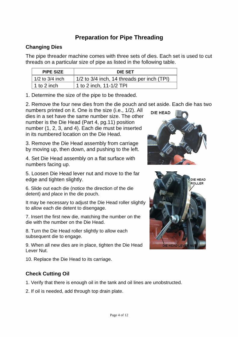
2. Remove the four new dies from the die pouch and set aside. Each die has two numbers printed on it. One is the size (i.e., 1/2). All dies in a set have the same number size. The other number is the Die Head (Part 4, pg.11) position number (1, 2, 3, and 4). Each die must be inserted in its numbered location on the Die Head.
3. Remove the Die Head assembly from carriage by moving up, then down, and pushing to the left.
4. Set Die Head assembly on a flat surface with numbers facing up.
5. Loosen Die Head lever nut and move to the far edge and tighten slightly.
6. Slide out each die (notice the direction of the die detent) and place in the die pouch.
It may be necessary to adjust the Die Head roller slightly to allow each die detent to disengage.
7. Insert the first new die, matching the number on the die with the number on the Die Head.
8. Turn the Die Head roller slightly to allow each subsequent die to engage.
9. When all new dies are in place, tighten the Die Head Lever Nut.
10. Replace the Die Head to its carriage.
Check Cutting Oil 1. Verify that there is enough oil in the tank and oil lines are unobstructed.
2. If oil is needed, add through top drain plate.
Page 4 of 12
3. When turned on, be sure oil is flowing from the Die Head before starting to cut threads.
Operation Now that the proper die set is installed, you are ready to insert the pipe, secure it, adjust Die Head roller to correct pipe size, and begin cutting threads.
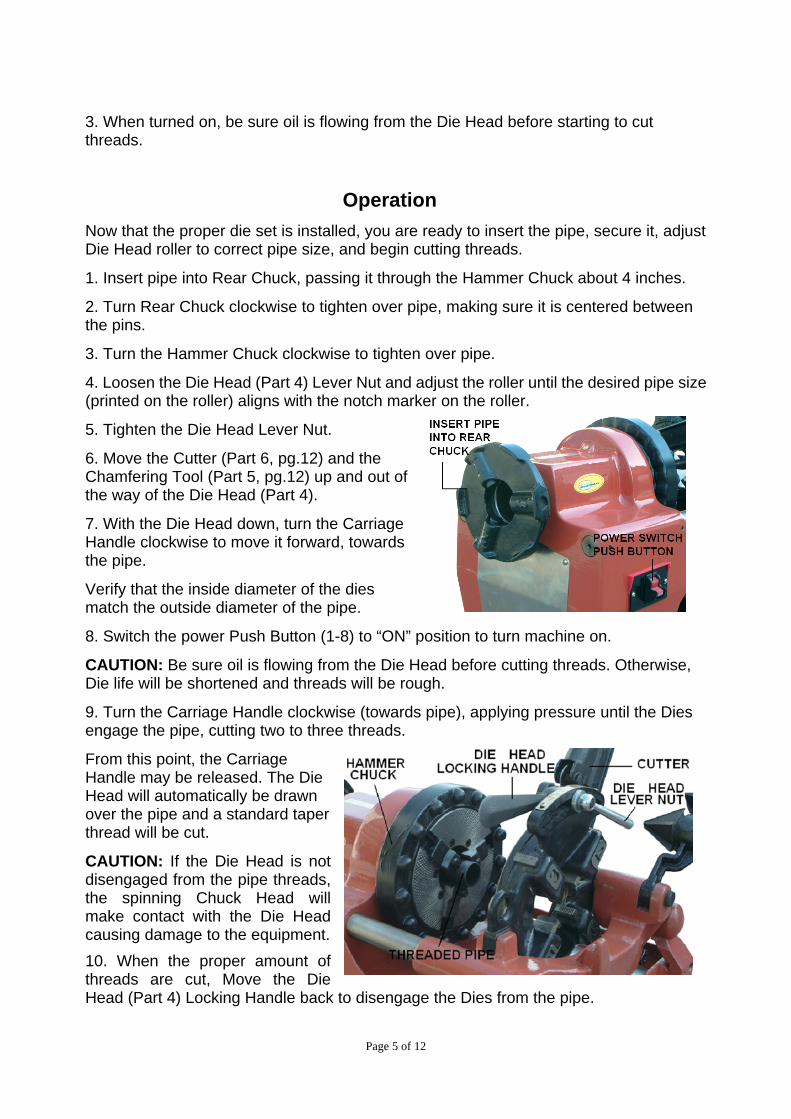
1. Insert pipe into Rear Chuck, passing it through the Hammer Chuck about 4 inches.
2. Turn Rear Chuck clockwise to tighten over pipe, making sure it is centered between the pins.
3. Turn the Hammer Chuck clockwise to tighten over pipe.
4. Loosen the Die Head (Part 4) Lever Nut and adjust the roller until the desired pipe size (printed on the roller) aligns with the notch marker on the roller.
5. Tighten the Die Head Lever Nut.
6. Move the Cutter (Part 6, pg.12) and the Chamfering Tool (Part 5, pg.12) up and out of the way of the Die Head (Part 4).
7. With the Die Head down, turn the Carriage Handle clockwise to move it forward, towards the pipe.
Verify that the inside diameter of the dies match the outside diameter of the pipe.
8. Switch the power Push Button (1-8) to “ON” position to turn machine on.
CAUTION: Be sure oil is flowing from the Die Head before cutting threads. Otherwise, Die life will be shortened and threads will be rough.
9. Turn the Carriage Handle clockwise (towards pipe), applying pressure until the Dies engage the pipe, cutting two to three threads.
From this point, the Carriage Handle may be released. The Die Head will automatically be drawn over the pipe and a standard taper thread will be cut.
CAUTION: If the Die Head is not disengaged from the pipe threads, the spinning Chuck Head will make contact with the Die Head causing damage to the equipment. 10. When the proper amount of threads are cut, Move the Die Head (Part 4) Locking Handle back to disengage the Dies from the pipe.
Page 5 of 12
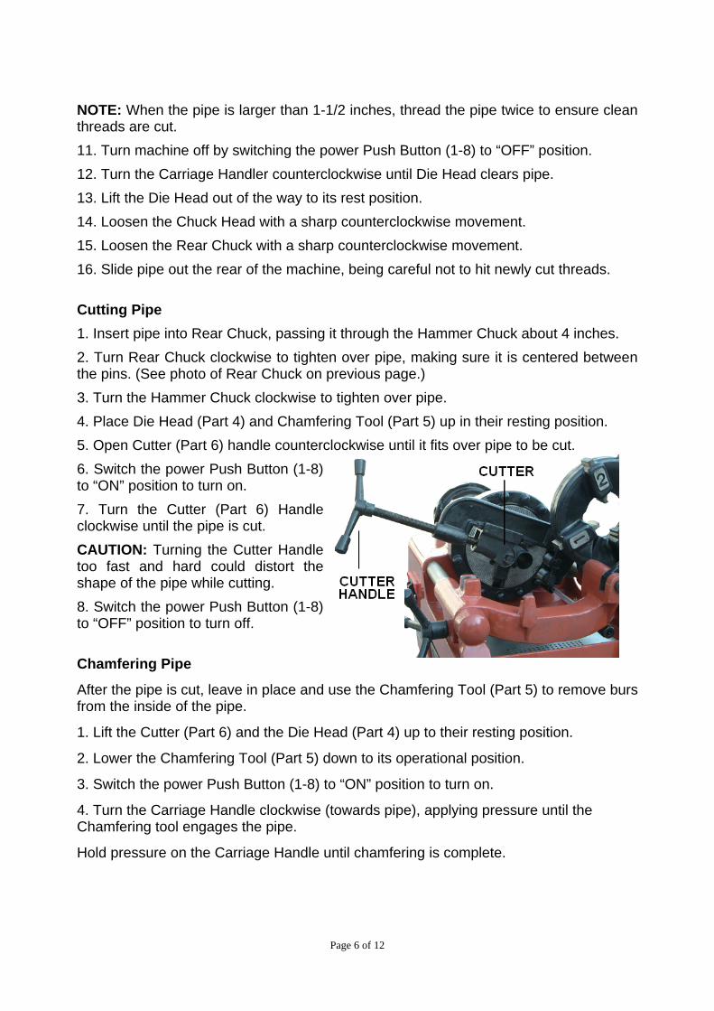
NOTE: When the pipe is larger than 1-1/2 inches, thread the pipe twice to ensure clean threads are cut. 11. Turn machine off by switching the power Push Button (1-8) to “OFF” position. 12. Turn the Carriage Handler counterclockwise until Die Head clears pipe. 13. Lift the Die Head out of the way to its rest position. 14. Loosen the Chuck Head with a sharp counterclockwise movement. 15. Loosen the Rear Chuck with a sharp counterclockwise movement. 16. Slide pipe out the rear of the machine, being careful not to hit newly cut threads. Cutting Pipe 1. Insert pipe into Rear Chuck, passing it through the Hammer Chuck about 4 inches. 2. Turn Rear Chuck clockwise to tighten over pipe, making sure it is centered between the pins. (See photo of Rear Chuck on previous page.) 3. Turn the Hammer Chuck clockwise to tighten over pipe. 4. Place Die Head (Part 4) and Chamfering Tool (Part 5) up in their resting position. 5. Open Cutter (Part 6) handle counterclockwise until it fits over pipe to be cut. 6. Switch the power Push Button (1-8) to “ON” position to turn on. 7. Turn the Cutter (Part 6) Handle clockwise until the pipe is cut. CAUTION: Turning the Cutter Handle too fast and hard could distort the shape of the pipe while cutting. 8. Switch the power Push Button (1-8) to “OFF” position to turn off.
Chamfering Pipe
After the pipe is cut, leave in place and use the Chamfering Tool (Part 5) to remove burs from the inside of the pipe.
1. Lift the Cutter (Part 6) and the Die Head (Part 4) up to their resting position.
2. Lower the Chamfering Tool (Part 5) down to its operational position.
3. Switch the power Push Button (1-8) to “ON” position to turn on.
4. Turn the Carriage Handle clockwise (towards pipe), applying pressure until the Chamfering tool engages the pipe.
Hold pressure on the Carriage Handle until chamfering is complete.
Page 6 of 12
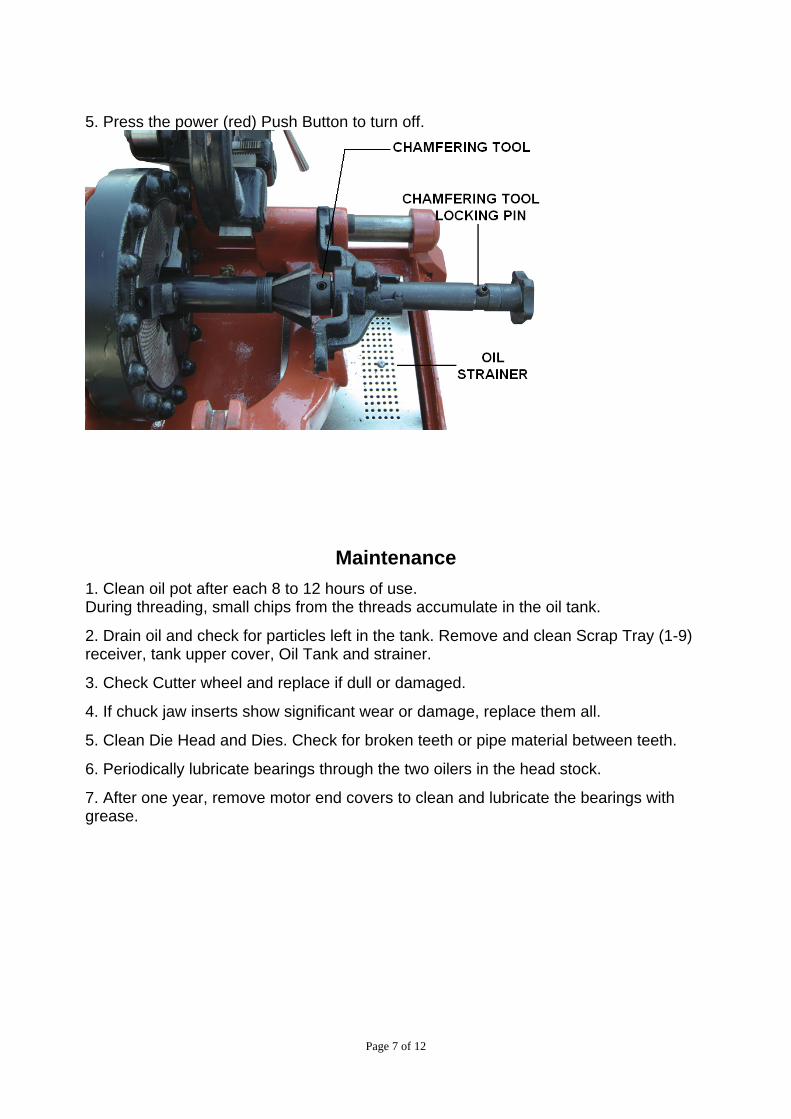
5. Press the power (red) Push Button to turn off.
Maintenance 1. Clean oil pot after each 8 to 12 hours of use. During threading, small chips from the threads accumulate in the oil tank.
2. Drain oil and check for particles left in the tank. Remove and clean Scrap Tray (1-9) receiver, tank upper cover, Oil Tank and strainer.
3. Check Cutter wheel and replace if dull or damaged.
4. If chuck jaw inserts show significant wear or damage, replace them all.
5. Clean Die Head and Dies. Check for broken teeth or pipe material between teeth.
6. Periodically lubricate bearings through the two oilers in the head stock.
7. After one year, remove motor end covers to clean and lubricate the bearings with grease.
Page 7 of 12

Troubleshooting
PROBLEM POSSIBLE CAUSE 1. Hammer Chuck not tight enough. 2. Chuck inserts need adjustment for equal grip. 3. A Chuck insert is broken. Replace entire set.
Pipe slipping while cutting threads
4. Die Head pipe size not set correctly. 1. Cutter wheel is dull. Sharpen. 2. Cutter wheel pin is dull. Replace.
Cutter wheel cannot cut pipe
3. Not enough force on the Cutter wheel handle. 1. Die Head not set correctly for pipe size. Set size index line to undersize position of pipe size. 2. One or more Die have broken teeth. Replace set. 3. Dies were installed incorrectly. Check numbers on Die and Die Head.
Dies cannot engage the pipe
4. Die Head slots contain small pipe chips. Clean Die Head and Dies. Hammer Chuck shakes when operating
1. Loose mounting screws. Tighten.
1. The main bearing has lost oil. Refill oil reserve. 2. Bearing is burned. Remove and replace bearing and
Main shaft generates heat or is making grinding noise,
main shaft. 1. Oil lines obstructed. Clean. 2. Die Head oil hole is not aligned with support shaft oil hole.
Oil pump working but oil not reaching Die Head
3. Insufficient oil reserve. Add oil. Lubricating oil getting into motor
1. Oil carriage sealant pump is damaged. Replace.
Page 8 of 12
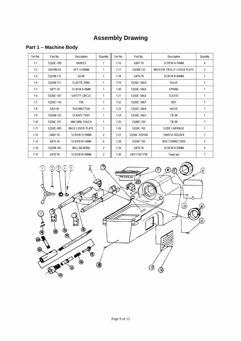
Assembly Drawing Part 1 – Machine Body
Ser No. Part No. Description Quantity Ser No. Part No. Description Quantity
1-1 SQ50C-109 HANDLE 1 1-16 GB67-76 SCREW 4×10MM 4
1-2 GB1096-92 KEY 5×20MM 1 1-17 SQ50B-122 BREATHE FREELY COVER PLATE 2
1-3 SQ50B-112 GEAR 1 1-18 GB70-76 SCREW 8×60MM 1
1-4 SQ50B-111 ELASTIC RING 1 1-19 SQ50C-106/3 VALVE 1
1-5 GB71-76 SCREW 6×8MM 1 1-20 SQ50C-106/5 SPRING 1
1-6 SQ50C-107 SAFETY CIRCLE 1 1-21 SQ50C-106/2 SLEEVE 1
1-7 SQ50C-110 PIN 1 1-22 SQ50C-106/1 NUT 1
1-8 KAO-5K PUSHBUTTON 1 1-23 SQ50C-106/4 VALVE 1
1-9 SQ50B-125 SCRAPS TRAY 1 1-24 SQ50C-106/7 TIE-IN 1
1-10 SQ50C-101 MACHINE SHUCK 1 1-25 SQ80C-103 TIE-IN 1
1-11 SQ50C-005 BACK COVER PLATE 1 1-26 SQ50C-102 SLIDE CARRIAGE 1
1-12 GB67-76 SCREW 5×10MM 2 1-27 SQ50C-103/104 SWITCH HOLDER 1
1-13 GB75-76 SCREW 8×16MM 4 1-28 SQ50C-105 BOX CONNECTION 2
1-14 SQ50B-102 BALL BEARING 2 1-29 GB70-76 SCREW 6×20MM 4
1-15 GB70-76 SCREW 8×30MM 2 1-30 GB117-85 5*30 Taper pin 1
Page 9 of 12
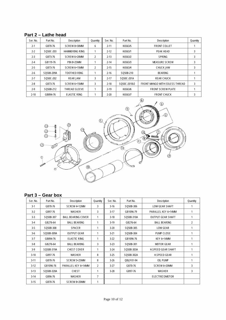
Part 2 – Lathe head Ser. No. Part No. Description Quantity Ser. No. Part No. Description Quantity
2-1 GB70-76 SCREW 8×30MM 6 2-11 K6563/5 FRONT COLLET 1
2-2 SQ50C-203 HAMMERING RING 1 2-12 K6563/1 PEAK HEAD 3
2-3 GB73-76 SCREW 6×20MM 2 2-13 K6563/2 SPRING 3
2-4 GB119-76 PIN 8×25MM 1 2-14 K6563/3 MEASURE SCREW 3
2-5 GB73-76 SCREW 6×15MM 2 2-15 K6563/4 CHUCK JAW 3
2-6 SQ50B-209A TOOTHED RING 1 2-16 SQ50B-210 BEARING 1
2-7 SQ50C-202 REAR JAM 3 2-17 SQ50C-201A REAR CHUCK 1
2-8 GB73-76 SCREW 6×15MM 3 2-18 SQ50C-201B/2 FRONT MANGO WITH EDLESS THREAD 3
2-9 SQ50B-212 THREAD SLEEVE 1 2-19 K6563/6 FRONT SCREW PLATE 1
2-10 GB894-76 ELASTIC RING 1 2-20 K6563/7 FRONT CHUCK 3
Part 3 – Gear box Ser. No. Part No. Description Quantity Ser. No. Part No. Description Quantity
3-1 GB70-76 SCREW 4×12MM 3 3-16 SQ50B-306 LOW GEAR SHAFT 1
3-2 GB97-76 WASHER 3 3-17 GB1096-79 PARALLEL KEY 6×14MM 1
3-3 SQ50B-307 BALL BEARING COVER 1 3-18 SQ50B-310A OUTPUT GEAR SHAFT 1
3-4 GB276-64 BALL BEARING 1 3-19 GB276-64 BALL BEARING 2
3-5 SQ50B-308 SPACER 1 3-20 SQ50B-305 LOW GEAR 1
3-6 SQ50B-309A OUTPUT GEAR 1 3-21 SQ50B-304 PUMP CLOSE 1
3-7 GB894-76 ELASTIC RING 1 3-22 GB1096-76 KEY 6×14MM 1
3-8 GB276-64 BALL BEARING 3 3-23 SQ50B-301 MOTOR GEAR 1
3-9 SQ50B-319A CHEST COVER 1 3-24 SQ50B-303A H.SPEED GEAR SHAFT 1
3-10 GB97-76 WASHER 8 3-25 SQ50B-302A H.SPEED GEAR 1
3-11 GB70-76 SCREW 5×25MM 8 3-26 QB/JF01-94 OIL PUMP 1
3-12 GB1096-76 PARALLEL KEY 6×14MM 2 3-27 GB70-76 SCREW 6×20MM 3
3-13 SQ50B-320A CHEST 1 3-28 GB97-76 WASHER 3
3-14 GB96-76 WASHER 7 ELECTRICOMOTOR
3-15 GB70-76 SCREW 8×20MM 1
Page 10 of 12
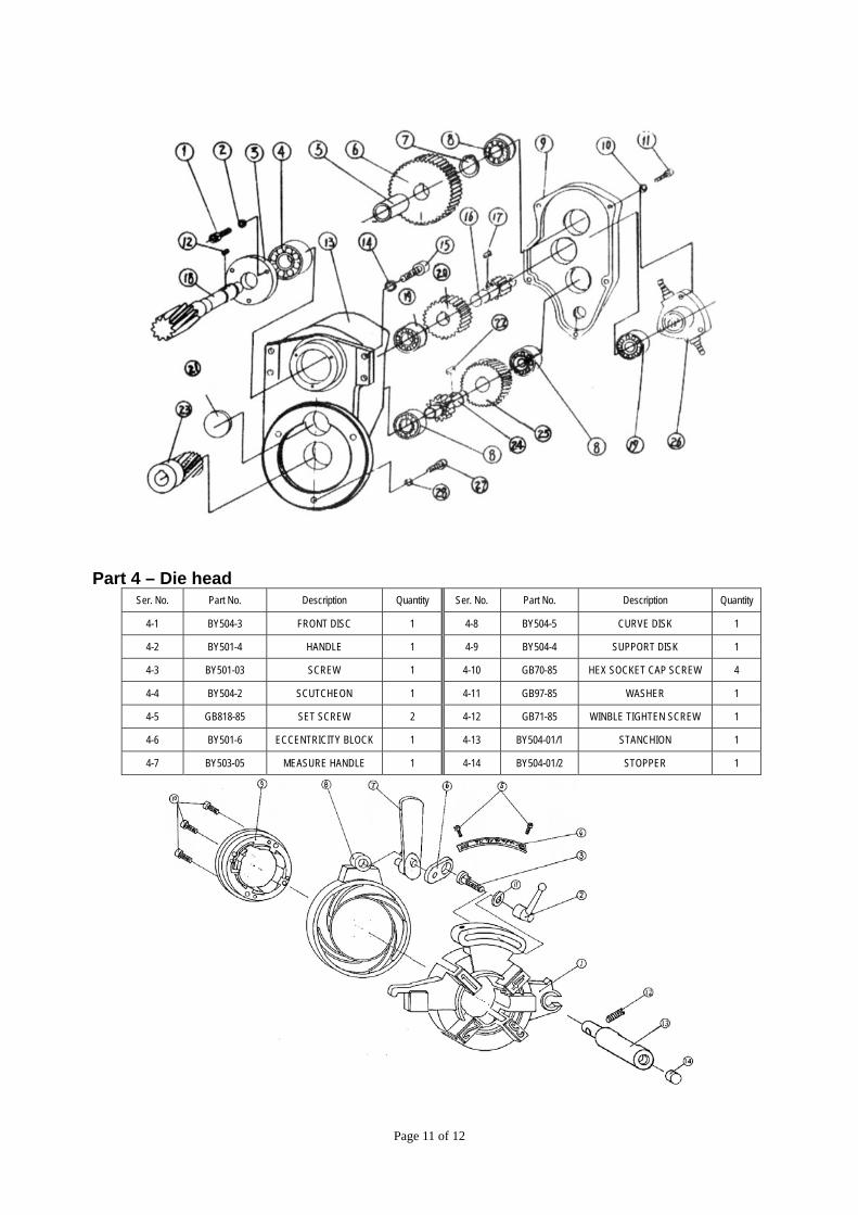
Part 4 – Die head Ser. No. Part No. Description Quantity Ser. No. Part No. Description Quantity
4-1 BY504-3 FRONT DISC 1 4-8 BY504-5 CURVE DISK 1
4-2 BY501-4 HANDLE 1 4-9 BY504-4 SUPPORT DISK 1
4-3 BY501-03 SCREW 1 4-10 GB70-85 HEX SOCKET CAP SCREW 4
4-4 BY504-2 SCUTCHEON 1 4-11 GB97-85 WASHER 1
4-5 GB818-85 SET SCREW 2 4-12 GB71-85 WINBLE TIGHTEN SCREW 1
4-6 BY501-6 ECCENTRICITY BLOCK 1 4-13 BY504-01/1 STANCHION 1
4-7 BY503-05 MEASURE HANDLE 1 4-14 BY504-01/2 STOPPER 1
Page 11 of 12
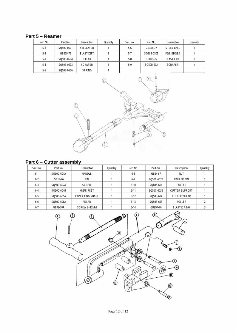
Part 5 – Reamer Ser. No. Part No. Description Quantity Ser. No. Part No. Description Quantity
5-1 SQ50B-0501 STELLATED 1 5-6 GB308-77 STEEL BALL 1
5-2 GB879-76 ELASTICITY 1 5-7 SQ50B-0505 FIVE EDGES 1
5-3 SQ50B-0504 PILLAR 1 5-8 GB879-76 ELASTICITY 1
5-4 SQ50B-0503 SCRAPER 1 5-9 SQ50B-502 SCRAPER 1
5-5 SQ50B-0506 SPRING 1
Part 6 – Cutter assembly Ser. No. Part No. Description Quantity Ser. No. Part No. Description Quantity
6-1 SQ50C-601A HANDLE 1 6-8 GB54-87 NUT 1
6-2 GB19-76 PIN 1 6-9 SQ50C-607B ROLLER PIN 2
6-3 SQ50C-602A SCREW 1 6-10 SQ80A-606 CUTTER 1
6-4 SQ50C-604B KNIFE REST 1 6-11 SQ50C-603B CUTTER SUPPORT 1
6-5 SQ50C-605A CONECTING SHAFT 1 6-12 SQ50B-604 CUTTER PILLAR 1
6-6 SQ50C-606A PILLAR 1 6-13 SQ50B-605 ROLLER 2
6-7 GB79-76A SCREW 8×12MM 1 6-14 GB894-76 ELASTIC RING 3
Page 12 of 12