is 8329 (2000): centrifugally cast (spun) ductile … iron and cast iron sectional committee, mtd 6...
TRANSCRIPT

Disclosure to Promote the Right To Information
Whereas the Parliament of India has set out to provide a practical regime of right to information for citizens to secure access to information under the control of public authorities, in order to promote transparency and accountability in the working of every public authority, and whereas the attached publication of the Bureau of Indian Standards is of particular interest to the public, particularly disadvantaged communities and those engaged in the pursuit of education and knowledge, the attached public safety standard is made available to promote the timely dissemination of this information in an accurate manner to the public.
इंटरनेट मानक
“!ान $ एक न' भारत का +नम-ण”Satyanarayan Gangaram Pitroda
“Invent a New India Using Knowledge”
“प0रा1 को छोड न' 5 तरफ”Jawaharlal Nehru
“Step Out From the Old to the New”
“जान1 का अ+धकार, जी1 का अ+धकार”Mazdoor Kisan Shakti Sangathan
“The Right to Information, The Right to Live”
“!ान एक ऐसा खजाना > जो कभी च0राया नहB जा सकता है”Bhartṛhari—Nītiśatakam
“Knowledge is such a treasure which cannot be stolen”
“Invent a New India Using Knowledge”
है”ह”ह
IS 8329 (2000): Centrifugally Cast (Spun) Ductile IronPressure Pipes for Water, Gas and Sewage [MTD 6: Pig ironand Cast Iron]

IS 8329 : 2000
Indian Standard
CENTRIFUGALLY CAST (SPUN) DUCTILE IRON PRESSURE PIPES FOR WATER, GAS
AND SEWAGE - SPECIFICATION
( Third Revision)
ICS 23.040.10; 23.040.40
0 BIS 2000
BUREAU OF INDIAN STANDARDS MANAK BHAVAN, 9 BAHADUR SHAH ZAFAR MARG
NEW DELHI 110002
February 2000 Price Group 8
Pig Iron and Cast Iron Sectional Committee, MTD 6
FOREWORD
This Indian Standard (Third Revision) was adopted by the Bureau of Indian Standards, after the draft finalized by the Pig Iron and Cast Iron Sectional Committee had been approved by the Metallurgical Engineering Division Council.
This standard was first published in 1977 and then revised in 1990 and 1994. While revising this standard, in light of the experience gained during these years, the committee has decided to revise this standard taking note of the revision and publication of EN 545 : 1994 and IS0 2531 : 1998 (E).
In this revision the following main modifications have been made:
4 b)
c)
4 4
fl
g)
Definition of various terms have been included to avoid ambiguity;
Dimensions from DN 80 to DN 2000 have been incorporated aligning them with IS0 253 1 : 1998 (E) and EN 545 : 1994;
Thickness of Class K7 and K8 have been increased based on current International practice and method of production facilities in this country;
Requirements for coating and lining have been modified,
To have a proper control on the quality of the pipes, a clause on quality assurance has also been incorporated;
The standard has been generally updated taking into account the modern trend in this respect in other International specifications particularly the current changes made in EN 545 : 1994 and IS0 253 1 : 1998 (E); and
As per current international practice, requirements of mass has been deleted from the standard.
Ductile iron, also called nodular iron or spheroidal graphite iron, is characterized by the presence of graphite in nodular or spheroidal form in the resultant casting. It differs from cast iron by greater tensile strength and its significant elongation at break. Ductile iron offers:
a) high resistance against breakage due to impact;
b) high tensile strength, comparable to that of mild steel so that the pipes can be used for higher working pressure;
c) traditional corrosion resistance, comparable to that of cast iron; and
d) lighter in mass as compared to cast iron pipes.
In order to have International co-ordination and harmonization with other International Standards, assistance has been derived from the following publications:
IS0 2531 : 1998(E) Ductile iron pipes, fittings and accessories and their joints for water or gas application, issued by the International Organization for Standardization
(ISO)
IS0 7186 : 1996(E) Ductile iron products for sewage applications
IS0 4179 : 1985 Ductile iron pipes for pressure and non-pressure pipelines - Centrifugal cement mortar lining - General requirements
IS0 8179-l : 1995 Ductile iron pipes - External coating: Part 1 Metallic zinc with finishing layer
IS0 8179-2 : 1995 Ductile iron pipes - External coating: Part 2 Zinc rich paint with finishing layer
IS0 8180 : 1985 Ductile iron pipes -Polyethylene sleeving
(Continued on third cover)
IS 8329 : 2000
Indian Standard
CENTRIFUGALLY CAST (SPUN) DUCTILE IRON PRESSURE PIPES FOR WATER, GAS AND SEWAGE - SPECIFICATION
( Third Revision ) 1 SCOPE
1.1 This standard specifies the requirements and associated test methods applicable to ductile iron pipes manufactured in metal (lined or unlined) or sand moulds and their joints for the construction of pipe lines:
- to convey water, sewage or gas
- to be installed below or above ground - operated with or without pressure
NOTES
I By sand it is to be understood.sand or mineral based materials used in foundry trade irrespective ofthe type of bonding agents.
2 All pressures are relative pressures expressed in MPa (IMPa = 10 bar).
1.2 This standard also specifies requirements for materials, dimensions and tolerances, mechanical properties and standard coatings and linings of ductile iron pipes.
1.2.1 This standard does not restrict the use of other types of joints or future developments of other joints as long as overall dimensions are maintained for reasons of safety and interchangeability.
1.3 The standard applies to pipes, which are:
manufactured with socketted, flanged or spigot ends for jointing by means of various types of gaskets, which are not with in the scope of this standard, and normally to be delivered externally and internally lined and are suitable for fluid temperatures between 0°C and 5O”C, excluding frost.
1.4 This standard does not include the provisions for fittings used with the pipes conforming to this standard. A separate standard IS -9523 covers the specification on such fittings.
1.5 Fittings conforming to IS 13382 may also be used with ductile iron pipes, when the pressure require- ments matches.
2 REFERENCES
The following Indian Standards contain provisions, which through reference in this text, constitute provisions of this standard. At the time of publication,
the editions indicated were valid. All standards are subject to revision and~parties to agreements based on this standard are encouraged to investigate the possibility of applying the most recent editions of the standards indicated below:
IS No. 455 : 1989
638 : 1979
1387 : 1993
1500 : 1983
1608 : 1995
5382 : 1985
6452 : 1989
6909 : 1990
8112 : 1989
9523 : 1980
11606 : 1986
12330 : 1988 13382 : 1992
Title Portland slag cement (fourth revision) Sheet rubber jointing and rubber insertion jointing (second revision) General requirements for supply of metallurgical materials (second revision) Methods for Brine11 hardness test for metallic materials (second revision) Mechanical testing of metals - Tensile testing (second revision) Rubber sealing ring for gas mains, water mains and sewers Cfirst revision) Specification for high alumina cement for structural use Specification for supersulphated cement 43 grade ordinary Portland. cement (first revision) Ductile iron fittings for pressure pipes for water, gas and sewage Methods of sampling of cast iron pipes and fittings Sulphate resisting Portland cement Cast iron specials for mechanical and push-on-flexible joints for pressure pipelines for water, gas and sewage
3 TERMINOLOGY
3.0 For the purpose of this standard, the following definitions shall apply:
3.1 Ductile Iron - Type of iron used for pipes, in which graphite is present primarily in spheroidal or nodular form.
3.2 Pipe- Casting of uniform bore, straight in axis, having either socket, spigot or flanged ends.
IS8329:2000
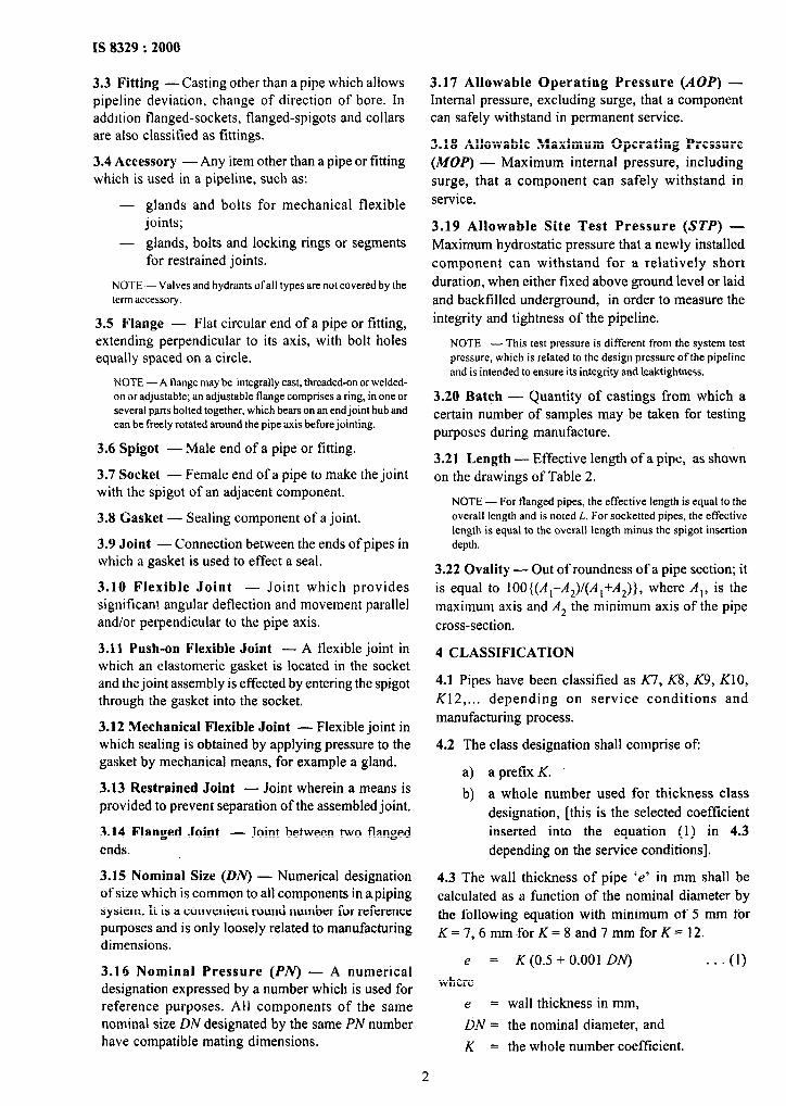
3.3 Fitting -Casting other than a pipe which allows pipeline deviation, change of direction of bore. In addition flanged-sockets, flanged-spigots and collars are also classified as fittings.
3.4 Accessory -Any item other than a pipe or fitting which is used in a pipeline, such as:
- glands and bolts for mechanical flexible joints;
- glands, bolts and locking rings or segments for restrained joints.
NOTE - Valves and hydrants ofall types are not covered by the term accessory.
3.5 Flange - Flat circular end of a pipe or fitting, extending perpendicular to its axis, with bolt holes equally spaced on a circle.
NOTE -A flange may be integrally cast, threaded-on or welded- on or adjustable; an adjustable flange comprises a ring, in one or several parts bolted together, which bears on an endjoint hub and can be freely rotated around the pipe axis before jointing.
3.6 Spigot - Male end of a pipe or fitting.
3.7 Socket - Female end of a pipe to make the joint with the spigot of an adjacent component.
3.8 Gasket - Sealing component of a joint.
3.9 Joint - Connection between the ends of pipes in which a gasket is used to effect a seal.
3.10 Flexible Joint - Joint which provides significant angular deflection and movement parallel and/or perpendicular to the pipe axis.
3.11 Push-on Flexible Joint - A flexible joint in which an elastomeric gasket is located in the socket and the joint assembly is effected by entering the spigot through the gasket into the socket.
3.12 Mechanical Flexible Joint - Flexible joint in which sealing is obtained by applying pressure to the gasket by mechanical means, for example a gland.
3.13 Restrained Joint - Joint wherein a means is provided to prevent separation of the assembled joint.
3.14 Flanged Joint - Joint between two flanged ends.
3.15 Nominal Size (ON) - Numerical designation of size which is common to all components in apiping system. It is a convenient round number for reference purposes and is only loosely related to manufacturing dimensions.
3.16 Nominal Pressure (PiV) - A numerical designation expressed by a number which is used for reference purposes. All components of the same nominal size DN designated by the same PN number have compatible mating dimensions.
3.17 Allowable Operating Pressure (AOP) - Internal pressure, excluding surge, that a component can safely withstand in permanent service.
3.18 Allowable Maximum Operating Pressure (MOP) - Maximum internal pressure, including surge, that a component can safely withstand in service.
3.19 Allowable Site Test Pressure (STP) - Maximum hydrostatic pressure that a newly installed component can withstand for a relatively short duration, when either fixed above ground level or laid and backfilled underground, in order to measure the integrity and tightness of the pipeline.
NOTE - This test pressure is different from the system test pressure, which is related to the design pressure ofthe pipeline and is intended to ensure its integrity and leaktightnens.
3.20 Batch - Quantity of castings from which a certain number of samples may be taken for testing purposes during manufacture.
3.21 Length - Effective length of a pipe, as shown on the drawings of Table 2.
NOTE - For flanged pipes, the effective length is equal to the overall length and is noted L. For socketted pipes, the effective
length is equal to the overall length minus the spigot insertion
depth.
3.22 Ovality - Out of roundness of a pipe section; it is equal to lOO{(A,-A,)l(A,+A,)}, where A,, is the maximum axis and A, the minimum axis of the pipe cross-section.
4 CLASSIFICATION
4.1 Pipes have been classified as K7, K8, K9, KIO, K12,... depending on service conditions and manufacturing process.
4.2 The class designation shall comprise of:
a) a prefix K.
b) a whole number used for thickness class designation, [this is the selected coefficient inserted into the equation (1) in 4.3 depending on the service conditions].
4.3 The wall thickness of pipe ‘e’ in mm shall be calculated as a function of the nominal diameter by the following equation with minimum of 5 mm for K=7,6mmforK=8and7mmforK=12.
e = K (0.5 + 0.001 Oh') . . . (1)
where
e = wall thickness in mm,
DN = the nominal diameter, and
K = the whole number coefficient.
2
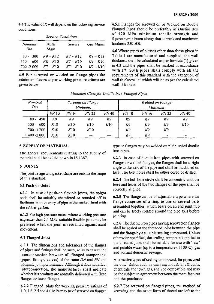
4.4 The value of K will depend on the following service conditions:
Service Conditions
Nominal Water Sewers Gas Mains Dia Main
80- 300 K9-K12 K7-K12 K9-K12 350 - 600 K8 - KlO K7 - KlO K9-KlO 700 -2 000 K7 - KlO K7-KlO K9 - KlO
4.5 For screwed or welded eon flange pipes the minimum classes as per working pressure criteria are given below:
IS 8329 : 2000
4.5.1 Flanges for screwed on or Welded on Double Flanged Pipes should be preferably of Ductile Iron of 420 MPa minimum tensile strength and 5 percent minimum elongation at break and maximum hardness 250 HB.
4.6 Where pipes of classes other than those given in Table 1 are manufactured and supplied, the wall thickness shall be calculated as per formula (1) given in 4.3 and the pipes shall be marked in accordance with 17. Such pipes shall comply with all the requirements of this standard with the exception of wall thickness ‘e’ which will be as per the calculated wall thickness.
Minimum Class for Ductile Iron Flanged Pipes
Nominal Dia
Screwed on Flange Minimum
Welded on Flange Minimum
PN 10 PN 16 PN25 PN 40 PN 10 PN16 PN25 PN 40
80 - 450 K9 K9 K9 K9 K9 K9 K9 K9 500 - 600 KlO KlO KlO KlO K9 K9 K9 KlO 700 -1 200 KIO KlO KlO - K9 K9 K9 -
1 400 -2 000 Klb KlO - - K9 K9 - -
5 SUPPLY OF MATERIAL
The general requirements relating to the supply of material shall be as laid down in IS 1387.
type or flanges may be welded on plain ended ductile iron pipes.
6 JOINTS
The joint design and gasket shape are outside the scope of this standard.
6.2.3 In case of ductile iron pipes with screwed on flanges or welded flanges, the flanges shall be at right angle to the axis of the pipe and shall be machined on face. The bolt holes shall be either cored or drilled.
6.1 Push-on-Joint
6.1.1 In case of push-on flexible joints, the spigot ends shall be suitably chamfered or rounded off to facilitate smooth entry of pipe in the socket fitted with the rubber gasket.
6.2.4 The bolt hole circle shall be concentric with the bore and holes of the two flanges of the pipe shall be correctly aligned.
6.1.2 For high pressure mains where working pressure isgreater than 2.4 MPa, suitable flexible joint may be preferred when the joint is restrained against axial movement.
6.2.5 The flange can be of adjustable type where the flange comprises of a ring, in one or several parts assembled together, which bears on an end joint hub and can be freely rotated around the pipe axis before jointing.
6.2 Flanged Joint
6.2.1 The dimensions and tolerances of the flanges of pipes and fittings shall be such, so as to ensure the interconnection between all flanged components (pipes, fittings. valves) of the same DN and PN and adequate joint performance. Although it does not affect interconnection, the manufacturer shall indicate whether his products are normally delivered with fixed flanges or loose flanges.
6.2.6 The ductile iron pipes having screwed on flanges shall be sealed at the threaded joint between the pipe and theflange by a suitable sealing compound. Unless otherwise specified, the sealing compound~applied to the threaded joint shall be suitable for use with ‘raw’ and~potable water (up to a temperature of 1 OO’C), gas and normal domestic sewage.
Alternative types of sealing compound, for pipes used for other duties such as carrying industrial effluents, chemicals and town gas, shall be compatible and may be the subject to agreement between the manufacturer and the purchaser.
6.2.2 Flanged joints for working pressure ratings of 6.2.7 For screwed on flanged pipes, the method of 1.0, 1.6,2.5 and 4.0 MPa may be of screwed onflanged screwing and the exact form of thread are left to the
3
IS 8329 : 2000
discretion of the manufacturer in view of the fact that flanges are never removed after screwing on the barrels of the pipes.
6.2.8 Dimensions of screwed on flanges and welded on flanges for ductile iron pipes shall conform to the requirements of Tables 3, 4, 5 and 6.
7.3 Pipes centrifugally cast shall be heat-treated in order to achieve the necessary mechanical properties and to relieve casting stresses caused due to the method of manufacture and repair work.
7.3.1 If necessary the pipes may be subjected to reheat treatment to ensure that Brine11 hardness does
6.3 Flexible Joints and Interconnection not exceed the specified value and the other mechanical properties specified in the standard are achieved.
Pipes with flexible joints shall be in accordance with 15 of this standard for their spigot external 8 RUBBER GASKET diameters DE and their tolerances. This provides the possibility of interconnection between components
8.1 Rubber gaskets used with push-on-joints or
equipped with different types of flexible joints. mechanical joints shall conform to IS 5382.
NOTES 8.2 Material of rubber gaskets for push-on mechanical or flanged joints shall be compatible with the fluid to be conveyed at the working pressure and temperature.
1 For interconnection with certain types ofjoints operating within
a tighter tolerance range on DE, the manufacturer’s guidance may
be followed as to the means ofensuringadequatejoint performance
up to the highest pressures (for example, measurement and
selection ofextemal diameter).
8.3 Rubber gaskets for mechanical joint for conveyance of town gas may be suitably protected so that the elastomer does not come in direct contact with the gas.
2 For interconnection with existing pipelines, which may have
external diameters not m compliance with 15, the manufacturer’s
guidance may be followed as to the appropriate means of
intkrconnection (for example, adaptors).
6.4 Restrained Joints
The design of restrained joints for ductile iron pipelines and its requirements shall be subject to agreement between the purchaser and the manufacturer as agreed at the time of enquiry and order. Their spigot external diameters DE and their tolerances shall be in accordance with requirements of 15.
7 MANUFACTURE
7.1 The metal used for the manufacture of pipes shall be of good quality, commensurate with the mechanical requirements laid down in 10. It shall be manufactured by any method at the discretion of the manufacturer provided that the requirements defined in this standard are complied with.
8.4 Rubber gaskets for use with flanged joints shall conform to IS 638.
8S’While conveying potable water the gaskets should not deteriorate the quality of water and should not impart any bad taste or foul odour.
9 SAMPLING
9.1 Sampling criteria for various tests, unless specified in this standard, shall be as laid down in IS 11606.
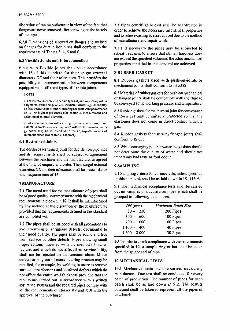
9.2 The mechanical acceptance tests shall be carried out on samples of ductile iron pipes which shall be grouped in following batch sizes.
DN (mm) Maximum Batch Size
80- 250 200 Pipes 300- 600 100 Pipes
7.2 The pipes shall be stripped with all precautions to 700 - 1 000 60 Pipes
avoid warping or shrinkage defects, detrimental to 1 100 - 1 400 40 Pipes
their good quality. The pipes shall be sound and free 1 600 - 2 000 30 Pipes
from surface or other defects. Pipes showing small imperfections inherited with the method of manu-
9.3 In order to check compliance with the requirements
facture, and which do not affect their serviceability, specified in 10, a sample ring or bar shall be taken
shall not be rejected on that account alone. Minor from the spigot end of pipe.
defects arising out of manufacturing process may be rectified, for example, by welding in order to remove surface imperfections and localized defects which do not affect the entire wall thickness provided that the repairs are carried out in accordance with a written assurance system and the repaired pipes comply with all the requirements of classes K9 and KlO with the approval of the purchaser.
10 MECHANICAL TESTS
10.1 Mechanical tests shall be carried out during manufacture. One test shall be conducted for every batch of production. The number of pipes for each batch shall be as laid down in 9.2. The results obtained shall be taken to represent all the pipes of that batch.
4
IS 8329 : 2000
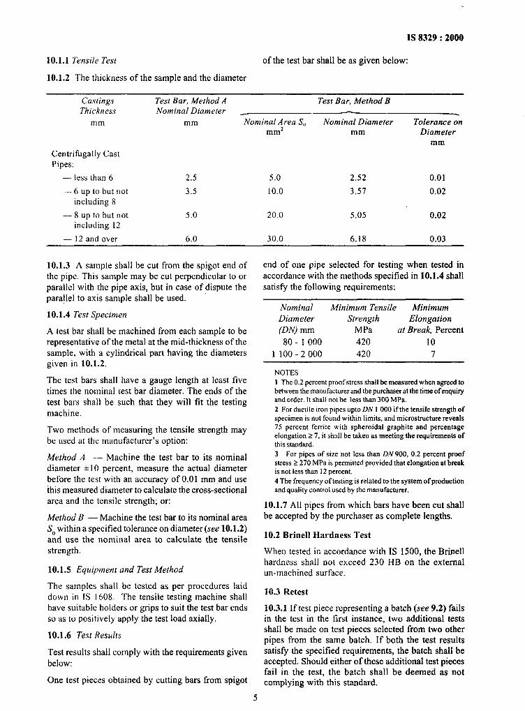
10.1.1 Tensile Test of the test bar shall be as given below:
10.1.2 The thickness of the sample and the diameter
Castings Test Bar, Method A Test Bar, Method B Thickness
mm
Centrifugally Cast Pipes:
Nominal Diameter _
mm Nominal Area S,, mm*
Nominal Diameter mm
Tolerance on Diameter
mm
- less than 6 2.5 5.0 2.52 0.01
- 6 up to but not 3.5 10.0 3.57 0.02 including 8
- 8 up to but not 5.0 20.0 5.05 0.02 including 12
- 12 and over 6.0 30.0 6.18 0.03
10.1.3 A sample shall be cut from the spigot end of the pipe. This sample may be cut perpendicular to or parallel with the pipe axis, but in case of dispute the
’ para!lel to axis sample shall be used.
10.1.4 Test Specimen
A test bar shall be machined from each sample to be representative of the metal at the mid-thickness of the sample, with a cylindrical part having the diameters given in 10.1.2.
The test bars shall have a gauge length at least five times the nominal test bar diameter. The ends of the test bars shall be such that they will fit the testing machine.
Two methods of measuring the tensile strength may be used at the manufacturer’s option:
Method A -- Machine the test bar to its nominal diameter *lo percent, measure the actual diameter before the test with an accuracy of 0.01 mm and use this measured diameter to calculate the cross-sectional area and the tensile strength; or:
Method B - Machine the test bar to its nominal area S, within a specified tolerance on diameter (see 10.1.2) and use the nominal area to calculate the tensile strength.
10.1.5 Equipment and Test Method
The samples shall be tested as per procedures laid down in IS 1608. The tensile testing machine shall have suitable holders or grips to suit the test bar ends so as to positively apply the test load axially.
10.1.6 Test Results
Test results shall comply with the requirements given below:
One test pieces obtained by cutting bars from spigot
5
end of one pipe selected for testing when tested in accordance with the methods specified in 10.1.4 shall satisfy the following requirements:
Nominal Minimum Tensile Minimum Diameter Strength Elongation (DN) mm MPa at Break, Percent 80 _ 1 000 420 10
1100-2000 420 7
NOTES
1 The 0.2 percent proof stress shall be measured when agreed to between the manufacturer and the purchaser at the time ofenquiry and order. It shall not be less than 300 MPa. 2 For ductile iron pipes upto DN I 000 ifthe tensile strength of specimen is not found within limits, and microstructure reveals 75 percent ferrite with spheroidal graphite and percentage elongation 5 7, it shall be taken as meeting the requirements of this standard. 3 For pipes of size not less than DN 900, 0.2 percent proof stress Z 270 MPa is permitted provided that elongation at break is not less than 12 percent. 4 The frequency oftesting is related to the system of production and quality control used by the manufacturer.
10.1.7 All pipes from which bars have been cut shall be accepted by the purchaser as complete lengths.
10.2 Brine11 Hardness Test
When tested in accordance with IS 1500, the Brine11 hardness shall not exceed 230 HB on the external un-machined surface.
10.3 Retest
10.3.1 If test piece representing a batch (see 9.2) fails in the test in the first instance, two additional tests shall be made on test pieces selected from two other pipes from the same batch. If both the test results satisfy the specified requirements, the batch shall be accepted. Should either of these additional test pieces fail in the test, the batch shall be deemed as not complying with this standard.
IS 8329 * 2V’O . Y
10.3.2 If test results do not satisfy the requirements of 10.1.6 the manufacturer shall:
In the case where the metal doss not achieve the required mechanical properties, investigate the reason and ensure that all castings in the batch are either re- heat treated or rejected.
NOTE -- If sufficient evidence is available that the failure ofthe sample can be attributed to defect in test bar, fresh sample may be drawn and tested. If It passes. the batch is accepted; if not the manufacrurer has the option to proceedas in 10.3.2.
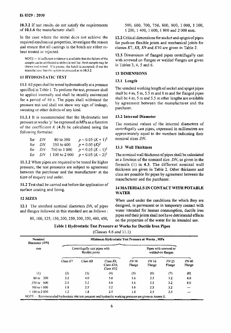
11 HYDROSTATIC TEST
11.1 All pipes shall be tested hydrostatically at a pressure
specified in Table 1. To perform the test, pressure shall be applied internally and shall be steadily maintained for a period of 10 s. The pipes shall withstand the pressure test and shall not show any sign of leakage, sweating or other defects of any kind.
11.1.1 It is recommended that the Hydrostatic test pressure at works ‘p’ be expressed in MPa as a function of the coefficient K (4.3) be calculated using the following formulae:
for DN 80 to 300 p = 0.05 (K + 1)2 for DN 350 to 600 p = 0.05 (K)2 for DN 700 to 1 000 p = 0.05 (K- I)* for DN 1 lOOto ~=0.05(K-2)~
11 .1.2 When pipes are required to be tested for higher
pressure, the test pressures are subject to agreement between the purchaser and the manufacturer at the time of enquiry and order.
11.2 Test shall be carried out before the application of surface coating and lining.
12 SIZES
12.1 The standard nominal diameters DN, of pipes and flanges followed in this standard are as follows :
80, 100, 125, 150,200,250,300,350,400,450,
500, 600, 700, 750, 800, 900, 1000, 1 100, 1 200, 1 400, 1 600, 1 800 and 2 000 mm.
12.2 Critical dimensions for socket and spigot of pipes for push-on flexible joints and mechanical joints for classes K7, K8, K9 and KlO are given in Table 2.
12.3 Dimensions of flanged pipes centrifugally cast with screwed on flanges or welded flanges are given in Tables 3, 4, 5 and 6.
13 DIMENSIONS
13.1 Length
The standard working length of socket and spigot pipes shall be 4 m, 5 m, 5.5 m and 6 m and for flanged pipes shall be 4 m, 5 m and 5.5 m other lengths are available by agreement between the manufacturer and the purchaser.
13.2 Internal Diameter
The nominal values of the internal diameters of centrifugally cast pipes, expressed in millimetres are approximately equal to the numbers indicating their nominal sizes DN.
13.3 Wall Thickness
The nominal wall thickness of pipes shall be calculated as a function of the nominal size. DN, as given in the formula (1) in 4.3. The different nominal wall thickness are given in Table 2. Other thickness and class are possible for pipes by agreement between the manufacturer and the purchaser.
14 MATERIALS IN CONTACT WITH POTABLE WATER
When used under the conditions for which they are designed, in permanent or in temporary contact with water intended for human consumption, ductile iron pipes and their joints shall not have detrimental effects on the properties of the water for its intended use.
Table 1 Hydrostatic Test Pressure at Works for Ductile Iron Pipes
(Clauses 4.6 and 11.1)
Nominal Minimum Hydrostatic Test Pressure at Works . MPa Diameter (DA’) -
mm Centrifugally cast pipes with Pipes with screwed 0; flexible joints welded-on flanges
Class A7 Class KS Class K9, PNIO PN16 PN25 PN40 Class KIO, Flange Flange Flange Flange Class K12
(1) (2) (3) (4) (5) (6) (7) (8)
80 to 300 3.2 4.0 5.0 1.6 2.5 3.2 4.0
350 to 600 2.5 3.2 4.0 1.6 2.5 3.2 4.0 7OG to 1 000 1.8 2.5 3.2 1.6 2.5 3.2 -
! looto2ooo I .2 1.8 2.5 1.6 2.5 2.5 -
NOTE -~ Recommended hydrostatic site test pressure and hydraulic working pressure are given in Annex E.
6
1s 8329 : 2000
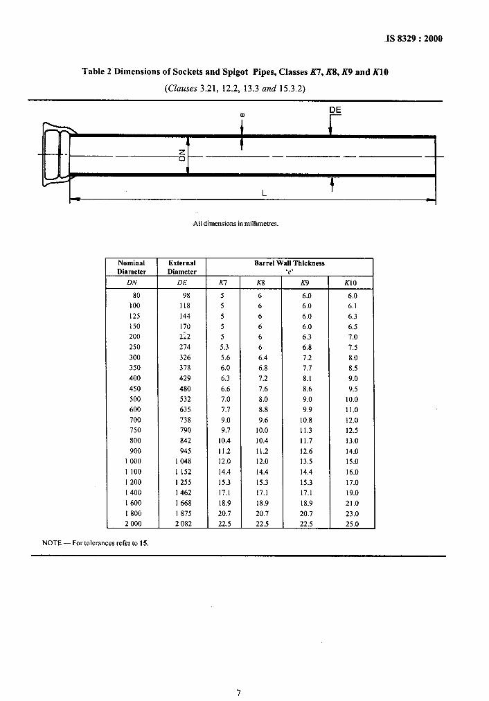
Table 2 Dimensions of Sockets and Spigot Pipes, Classes K7, KS, K9 and X10
(Clauses 3.21, 12.2, 13.3 and 15.3.2)
DE a,
Nominal Diameter
DN
External Diameter
DE
80 98
100 118
125 144
150 170
200 222
250 274
300 326
350 378
400 429
450 480
500 532
600 635
700 738
750 790
800 842
900 945
1000 1 048
1 100 1 152
I 200 I 255
I 400 I 462
I 600 1 668
I 800 I 875
2 000 2 082
All dimensions in millimetres.
Barrel Wall Thickness ‘0’ r
K-7 K8
5 6
5 6
5 6
5 6
5 6
5.3 6
5.6 6.4
6.0 6.8
6.3 7.2
6.6 7.6
7.0 8.0
7.7 8.8
9.0 9.6
9.7 10.0
10.4 10.4
11.2 11.2
12.0 12.0
14.4 14.4
15.3 15.3
17.1 17.1
18.9 18.9
20.7 20.7
22.5 22.5
c
K9
6.0
6.0
6.0
6.0
6.3
6.8
7.2
7.7
8.1
8.6
9.0
9.9
10.8
11.3
11.7
12.6
13.5
14.4
15.3
17.1
18.9
20.7
22.5
KIO
6.0
6.1
6.3
6.5
7.0
7.5
8.0
8.5
9.0
9.5
10.0
11.0
12.0
12.5
13.0
14.0
15.0
16.0
17.0
19.0
21.0
23.0
25.0
NOTE - For tolerances refer to 15.
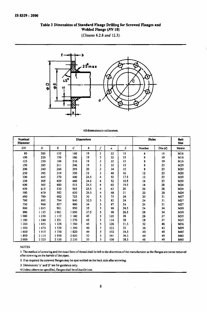
IS 8329 : 2000
Table 3 Dimenshs of Standard Flange Drilling for Screwed Flanges and Welded Flange (PA’ 10)
(Clauses 6.2.8 and 12.3).
All dimensions in millimetres.
Nominal Dimensions Holes Bolt Diameter Slu
DN D E C b / a S Number Dia (d) MCbiC
80 200 132 160 I9 3 32 I5 4 I9 Ml6
100 220 156 180 19 3 32 15 8 19 Ml6
I25 250 184 210 I9 3 32 I5 8 I9 Ml6
I50 285 211 240 I9 3 32 I5 ‘8 23 M20
200 340 266 295 20 3 34 I5 8 23 M20
250 395 319 350 I 22 3 48 I6 12 23 M20
300 445 370 400 24.5 4 52 17.5 I2 23 M20
350 505 429 460
I 24.5 4 52 19.5 I6 23 M20
400 565 480 515 24.5 4 60 19.5 16 28 .M24
450 615 530 565 25.5 4 63 20 20 28 M24
500 670 582 620 26.5 4 68 21 20 28 M24
600 780 682 725 30 5 75 24 20 3’1 M27
700 895 794 840 32.5 5 24
750 960”
82 24 31 M27
857 900 34 5 87 2-t 24 31 M27
800 1015 901 950 35 5 90 24.5 24 34 M30
900 I II5 1001 I 050 37.5 5 98 26.5 28 34 M30
I 000 I 230 I II2 I 160 40 5‘ I05 28 28 37 M33
I 100 I 340 1231 1270 43 5 II4 30 28 37 h433
I 200 I 455 I 328 I 380 45 5 120 31.5 32 40 M36
I 400 I 675 I 530 I 590 46 5 123 32 36 43 M39
I 600 I915 I 750 I 820 49 5 132 34.5 40 49 M45
I 800 2 115. I 950 2 020 52 5 I41 36.5 44 49 M45
2000 2 325 2150 2 230 55 5 I50 38.5 48 49 M45
NOTES
t The method ofscrewing and the exact form of thread shall be left to the discretion ofthe manufacturer as the flanges are never removed aRer screwing on the barrels oftbe pipes.
2 Ifso required the screwed flanges may be spot welded on the back side after screwing.
3 Dimensions ‘a’ and’S;are for guidance only.
4 Unless otherwise specified, flanges shall be ofductile iron.
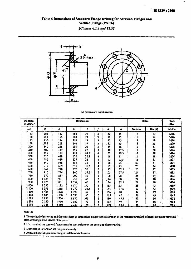
Table 4 Dimen$ions of Standard Flange Drilltag for Screwed Flanges and Welded Flange ~(PN 16)
(Clauses 6.2.8 and 12.3)
Nominal Diameter
DN
r 80
100 125 150 200 250 300 350 400 450 500 600 700 750 800 900
;t 1200 1400 I600 1800 2 000
NOTES
d
D -
& c b
200 132 160 19 220 156’ 180 19 250. ,184 210 19 285 211 240 19 340 266 295 20 400 31.9 355 22 455 370 410 24.5 520 429 470 26.5 580 480. 525 28 640 548 585 30 715 609 650 31,5 840 _ 720 770 36 910 794 840 39.5 970 857 900 41
1 025 901 950 43 1 125 1001 I OS& 46 1 255 1112 1 170 50 I 355 1218 I 270 53.5 1485 1328 I 390 57 1685 1 530 1 590 60 I 930 1 750 1620 65 2 130 1 950 2 020 70 2 345 2 150 2 230 75.
Dimensions
‘T- -I- 3 3 3- 3 3 4 4 4 4 4 5 5 5 5 5 5 5 5 5 5 5 5 -
a
32 32 32 32 34 48 52’ 68 72 78 82 93
103 108 114 124 135 144 156 165 180 195 210
s NUmba
I5 8 15 8 15 8 15 ‘8 16 12 17.5 12 ‘19.5 12 21 16 22.5 16 24 20 25 20 27.5 20 27.5 24 28 24 30 24 32.5 28 35 28 37.5 32 40 32 42 36 45.5 40 49 44 52.5 48
r L
Dia (d)
19 19 19 23 23 28
:: 31 31 34 37
:a.. ai 40 43 43 49 49 56
J MChiC
Ml6 Ml6 Ml6 M20 M20 fW M24 M24
.M27 Mz?
g;.
M33 M33 M36 .h436 M39
!z h&s
-f&32 -M52, -MS6
1 The method of screwing and the exact form of thread ,shrdl be IeD to the discretion of the manufrctunrW the flanges * ~nmdved after screwing on the barrels ofthe pipes.
2 If so required the screwed flanges may be spot welded on the back side after screwing.
3 Dimensions ‘0’ and’s’ are for guidance only.
4 Unless otherwise specifkd, flanges shall be ofductile iron.
9
IS 8329 : 2000
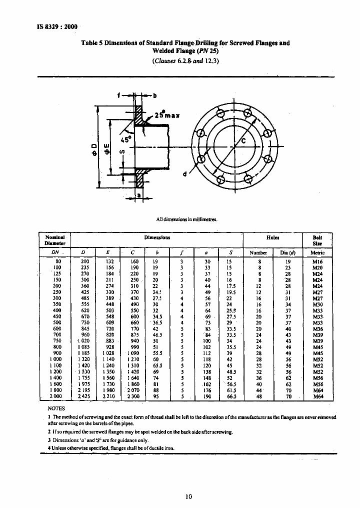
Table 5 Dimensioni of Standard FlangeDrilling for Screwed Flanges’and Welded Flange (PN 25)
(Clhuses 6.2.Ihzd12.3)
All dimensions in millimetms.
Nominal. Dimensions HOkS Bolt
Diameter Slxe
DN. D E ’ c b f a s Numba Dia (d) Metric
80 200 132 160 19 3 30 15 8 19 Ml6 100 235 156 190 19 3 33 is 8 23 Ii420 125 270 184 220 3 37 IS 8 28 M24 150 300 211 250
:‘o 3 40 16 8 ‘28 M24
200 360 274 310 22 3 44 17.5 12 28 M24 250 425 330 370 24.1 3 49 19.5 12 31 M27 300 485 389 430 27.5 4 56 22 16 31 M27 350 555 448 490 30 4 57 24 16 34 M30 400 620 503 550 32 4 64 25.3 16 37 M33 450 670 548 600 34.5 4 69 27.5 20 37 M33 500 730 609 660 36.5 4 73 29 20 37 M33 600 845 720 770 42 5 83 33.5 20 40 M36 700 960 820 875 46.5 5 -. 84 33.5 24 43 M39 750 -I 020 883 940 50 5 100 34 24 43 M39 800 I 085 928 990
::5 5 102 35.5 24 49 M45
900 I 185 I 028 1090 5 112 39 28 49 M45 1000 I 320 I 140 1210 60‘ 5 118 42 28 56 MS2 I loo 1420 I 240 1310 65.5 5 120 45 32 56 M52 I 200 1 530 I 350 1420 69 5 138 48.5 32 56 MS2 1400 1755 1560 1640 74 5 148 52 36 62 M56 1600 1975 1730 1860 81 5 162 ” 56.5 40 62 MS6 I 800 2 195 I 980 ‘2070 88 5 176 61.5 44 70 M64 2 000 2,425 2 210 2300 95 5. 190 66.5 48 70 . M64
NOTES
I The method of screwing and the exact form of thread shall be left to the discretion of the manufacturer as the flanges are. neverremoved after screwing on the barrels of the pipes.
2 If so required the screwed flanges may be spot welded on the back side after screwing.
3 Dimensions ‘a’ and~=r’ are for guidance only.
4 Unless otherwise specified, flanges shall be of ductile iron.
10
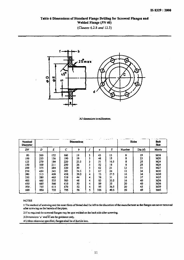
Table 6 Dimensions of Standard Flange Drilling for Screwed Flanges and Welded Flange (PN 40)
(Clauses 6.2.8 and 12.3)
Nominal .Diameter
DN D E c b
80 200 132 160 I9 100 235 156 190 I9 125 270 184 220 23.5 150 300 211 250 26 200 375 284 320 30 250 450 345 385 34.; 300 515 409 450 39.5 350 580 465 510 44 400 660 535 585 48 450 685 560 610 50 400 / 755 615 670 52 600 890 735 795’ 58
NOTES
All dimensions in millimetres.
T f - 3 3 3 3 3 3 4 4 4 4 4 5
a S Number Dia (d)
43 48 51 52 62 67 73 76 83
z; 106
I5 8 I9 Ml6 15 8 23 M20 16.5 8 28 M24 18 8 28 hG?4 21 12 31 M27 24 12 34 M30 27.5 1~6 34 M30 31 I6 37 M33 33.5 16 40 M36 35 20 40 M36 36.5 20 43 M39 40.5 20 49 M45
HOkS Bolt size
Metric
1 The method of screwing and the exact fo? of thread shall be left to the discretion of the manufacturer as the flanges are never removed after screwing on the barrels of the pipes.
2 Ifso required the screwed flanges may be spot welded on the back side’after screwing.
3 Dimensions ‘a’ and?&re forguidance only.
4 Unless otherwise specified, flanges shall be ofductile iron.
11
IS8329:2000
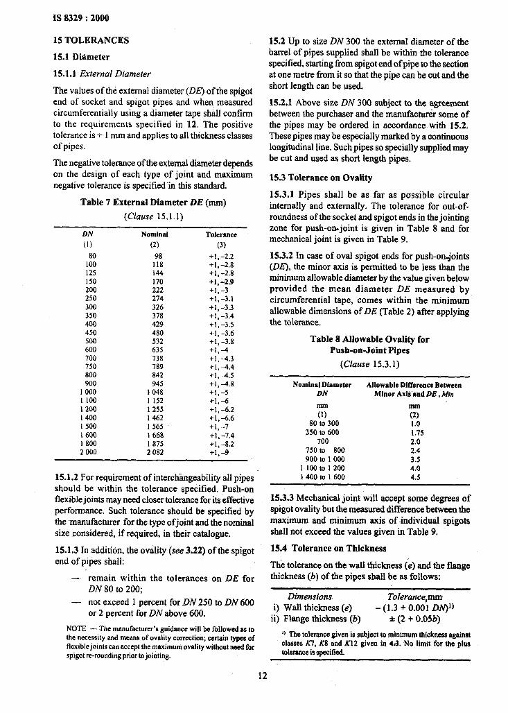
15 TOLERANCES
15.1 Diameter
15.1.1 External Diameter
The values of the external diameter (DE) of the spigot end of socket and spigot pipes and when measured circumfetentialiy using a diameter tape shall confirm to the requirements specified in 12. The positive tolerance is + 1 mm and applies to all thickness classes of pipes.
The negative tolerance of the external diameter depends on the design of each type of joint and maximum negative tolerance is specified in this standard.
Table 7 External Diameter DE (mm)
(Clause 15.1.1)
DN Nominal
(1) (2)
80 98 100 118 125 144 150 170 200 222 250 274 300 326 350 378 400 429 450 480 500 532 600 635 700 738 750 789 800 842 900 945
1 000 k 048 I 100 1 152 I 200 1255 I 400 1462 1 500 1 565 I 600 1 668 I 800 I 875 2 000 2 082
Tolerance
(3)
+1,-2.2 +I,-2.8 +A, -2.8 +1,-2.9 +1, -3 +1,-3.1 +1, -3.3 +1, -3.4 +1,-3.5 +I, -3.6 +I,-3.8 +1,-I +1,-4.3 +1, -4.4 +1,-4.5 +I, -4.8 +1,-s +1,-6 +1, -6.2 +1,-6.6 +1,-7 +1,-7.4 +I,-8.2 +1,-g
15.1.2 For requirement of interchangeability all pipes should be within the tolerance specified. Push-on flexible joints may need closer tolerance for its effective performance. Such tolerance should be specified by the -manufacturer for the type ofjoint and the nominal size considered, if required, in their catalogue.
15.1.3 In addition, the ovality (see 3.22) of the spigot end of pipes shall:
- remain within the tolerances on DE for DN 80 to 200;
- not exceed I percent for DN 250 to DN 600 or 2 percent for DN above 600.
NOTE -The manufacturer’s guidance will be followed as to the necessity and means of ovality correction; certain types of flexible joints can accept the maximum ovality without need tbr spigot re-rounding prior to jointing.
15.2 Up to size DN 300 the external diameter of the barrel of pipes supplied shall be within the tolerance specified, starting from spigot end of pipe to the section at one metre from it so that the pipe can be cut and the short length can be used.
15.2.1 Above size DN 300 subject to the agreement between the purchaser and the manufacturer some of the pipes may be ordered in accordance with 15.2. These pipes may be especially marked by a continuous longitudinal line. Such pipes so specially supplied may be cut and used as short length pipes.
15.3 Tolerance on Ovality
15.3.1 Pipes shall be as far as possible circular internally and externally. The tolerance for out-of- roundness of the socket and spigot ends in the jointing zone for push-on-joint is given in Table 8 and for mechanical joint is given in Table 9.
15.3.2 In case of oval spigot ends for push-onjoints (DE), the minor axis is permitted to be less than the minimum allowable diameter by the value given below provided the mean diameter DE measured by circumferential tape, comes within the minimum allowable dimensions of DE (Table 2) after applying the tolerance.
Table 8 Allowable Ova&y for Push-on-Joint Pipes
(Clause 153.1)
Nominal Diameter Allowable Difference Between DN Minor Axlb and DE, Min
mm mm
(1) (2) 80 to 300 I.0
350 to 600 1.75 700 2.0
750 to 800 2.4 900 to 1 000 3.5
1100to1200 4.0 1 400 to 1 600 4.5
15.3.3 Mechanical joint will accept some degrees of spigot ovality but the measured difference between the maximum and minimum axis of individual spigots shall not exceed the values given in Table 9.
15.4 Tolerance on Thickness
Thk tolerance on the wall thickness (e) and the flange thickness (6) of the pipes shall be as follows:
Dimensions. Tolerancepm i) Wall thickness (e) - (1.3 + 0.001 DN)‘)
ii) Flange thickness (b) i-(2 + 0.05b)
I) The tolerance given is subject to minimum thickness against classes KI, Kt? and Kl2 given in 4.3. No limit for the plus tokrance is specified.
12
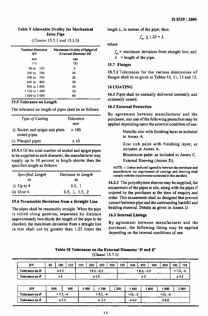
Table 9 Allowable Ovality for Mechanical Joint Pipe
(Clauses 15.3.1 and 15.3.3)
Nominal Diameter Maximum Ovality of Spigot of DN External Diameter DE
mm mm
(1) (2)
80to 150 5 200 to 350 IO 400 to 500 20 600 to 800 30 900 to I 000 40
I loot0 1400 50 I 600 to ,2 000 60
15.5 Tolerance on Length
The tolerance on length of pipes shall be as follows:
Type of Casting Tolerance mm
i) Socket and spigot and plain f 100 ended pipes
ii) Flanged pipes f 10
15.5.1 Of the total number of socket and spigot pipes to be supplied in each diameter, the manufacturer may supply up to 10 percent in length shorter than the specified length as follows:
Specified Length Decrease in Length m m
i) Up to 4 0.5, 1
ii) Over 4 0.5, 1, 1.5, 2
15.6 Permissible Deviation from a Straight Line
The pipes shall be reasonably straight. When the pipe is rolled along gantries, separated by distance approximately two-thirds the length of the pipe to be checked, the maximum deviation from a straight line in mm shall not be greater than 1.25 times the
IS 8329 : 2000
length L, in metres of the pipe; thus:
f, <1.25xL
where
fm = maximum deviation from straight line, and
L = length of the pipe.
15.7 Flanges
15.7.1 Tolerances for the various dimensions of flanges shall be as given in Tables 10, 11, 12 and 13.
16 COATING
16.1 Pipes shall be normally delivered internally and externally coated.
16.2 External Protection
By agreement between manufacturer and the purchaser, any one ofthe following protection may be applied depending upon the external condition of use:
‘Metallic zinc with finishing layer as included in Annex A.
Zinc rich paint with finishing layer, as included in Annex A.
Bituminous paint: as included in Annex C.
External Sleeving (Annex D).
NOTE -Unless and until agreed to between the purchaser and manufacturer the requirement of coatings and sleeving shall comply with the rcquinments contained in this standard.
16.2.1 The polyethylene sleeves may be supplied, for encasement of the pipes at site, along with the pipes if ordered by the purchaser at the time of enquiry and order. This encasement shall so designed that prevent contact between pipe and the surrounding backfill and bedding material. Details as given in Annex D.
16.3 Internal Linings
By agreement between manufacturer and the purchaser, the following lining may be applied depending on the internal conditions of use:
Table 10 Tolerances on-the External Diameter ‘D and E’ (Clause 15.7.1)
DN
Tolerance on D
Tolerance on E
DN
Tolerance on D
Tolerance on E
80 100 I25 150 1 200 1 250 300 350 1 400 1 450 1 500 1 600 700 750
f 4.5 +5.5, -2.5 + 6.5, -3.5 + 7.5, -4
l 4 l 4.5 *5 as.5
800 900 1000 1100 1200 1400 1600 1800 2000
+ 7.5, -4 + 8.5, A +10, -5 +12,-6
f 5.5 f 5.5 f 6.0 f 6.0
13
IS 8329 : 2000
- Portland cement (with or without additives) mortar, as included in Annex B.
- Blast furnace slag cement mortar as included in Annex B.
- High alumina (calcium aluminate) cement mortar as included in Annex B.
- Cement mortar with seal-coat: as included in Annex B.
Bituminous paint as included in Annex C.
NOTE - Unless and until agreed to between the purchaser and
the manufacturer, the requirement of internal lining shall comply
with the requirements contained in this standard.
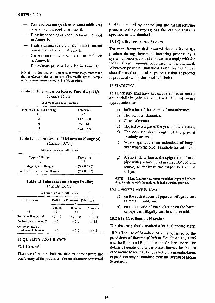
Table 11 Tolerances on Raised Face Height v) (Clause 15.7.1)
All dimensions in millimetres.
Height of Raised Face v) Tolerance
(I) (2)
3 +I 5, -2.0
4 +2, -3.0
5 +2.5,+.0
Table 12 Tolerances on Thickness on Flange (b) (Clause 15.7.1)
All dimensions in millimetres.
Type of Flange Tolerance
(1) (2)
Integrally cast flanges f (3 + 0.05 fr)
Welded and screwed on flanges * (2 + 0.05 b)
Table 13 Tolerances on Flange Drilling (Clause 15.7.1)
All dimensions in millimetres.
Dimension Bolt Hole Diameter, Tolerance --- 19to28 31 to56 Above 62
(1) (2) (3) (4)
Bolt hole diameter, d +2,-o +3,-o +-4, - 0
~Pitch circte diameter, C f 2 * 2.8 f 4.8
Centre to centre of
adjacent bolt holes *2 f 2.8 zk 4.8
17 QUALITY ASSURANCE
17.1 General
The manufacturer shall be able to demonstrate the conformity of the product to the requirement contained
in this standard by controlling the manufacturing process and by carrying out the various tests as specified in this standard.
17.2 Quality Assurance System
The manufacturer shall control the quality of the product during their manufacturing process by a system of process control in order to comply with the technical requirements contained in this standard. Wherever possible, statistical sampling techniques should be used to control the process so that the product is produced within the specified limits.
18 MARKING
18.1 Each pipe shall have as cast or stamped or legibly and indelibly painted on it with the following appropriate marks:
a) b) c) d) 4
Indication of the source of manufacture;
The nominal diameter;
Class reference;
The last two digits of the year of manufacture;
The non-standard length of the pipe if specially ordered;
Where applicable, an indication of length over which the pipe is suitable for cutting on site; and
A short white line at the spigot end of each pipe with push-on joint in sizes DN 700 and above, to indicate the major axis of the spigot.
NOTE - Manufacturers may recommend that spigot end ofsuch
pipes be jointed with the major~axis in the vertical position.
18.1.1 Marking may be Done
a) on the socket faces ofpipe centrifugally cast in metal mould, and
b) on the outside of the socket or on the barrel of pipe centrifugally cast in sand mould.
18.2 INS Certification Marking
The pipes may also be marked with the Standard Mark.
18.2.1 The use of Standard Mark is governed by the provisions of Bureau of Indian Standards Act, 1986 and the Rules and Regulations made thereunder. The details of conditions under which licence for the use .of Standard Mark may be granted to the manufacturers or producer may be obtained from the Bureau of Indian Standards.
14
IS 8329 : 2000
ANNEX A
(Clause 16.2)
ZINC COATING
A-l PIPE SURFACE CONDITION
The pipe surface shall be dry and free from rust or any non-adhering particles or foreign matter such as oil or grease. Metallic zinc shall be applied on to the oxide external surface of the pipe.
NOTE --~~ The zinc is normally applied on the pipe with oxide
skin but, at the manufacturer’s option, it may applied on a blast
cleaned pipe surface.
A-2 MATERIALS
The coating materials are metallic zinc with content of at least 99 percent by mass.
A-3 METHOD OF APPLICATION
The metallic zinc coating shall be applied by a spraying process in which metallic zinc material is heated to a molten state and projected in small droplets by spray guns onto surface. The zinc rich paint coating shall be applied by a spraying or a brush process onto the pipe surface in case of repair only.
A-4 COATING CHARACTERISTICS
A-4.1 The metallic zinc coating shall cover the outside diameter of the pipe and shall be free from such defects as bare patches or lack of adhesion.
A-4.2 Damaged areas of zinc coating caused by handling are acceptable provided that the damage is less than 5 cm2/m2 of coated surface and provided that the minor dimensions of the damaged area do not exceed 5 mm.
A-5 ZINC COATING MASS
The average mass of zinc coating shall be not less than 130 g/m* with a local minimum of 110 g/m*.
A-6 DETERMINATION OF ZINC COATING
Manufacturing process control system shall specify the frequency of this test. A rectangular token is attached along the pipe axis before passing it through the zinc coating equipment. After coating and trimming the minimum token sizes shall be either:
a) 250 mm,x 100 mm, or
b) 500 mm x 50 mm.
The average mass of zinc coating M expressed in
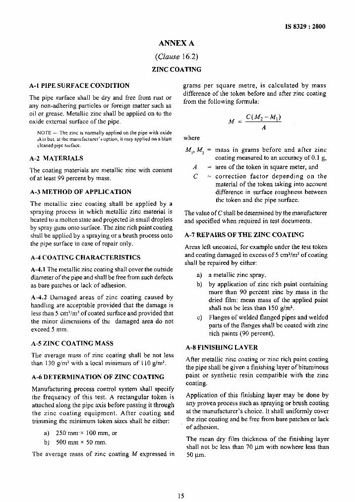
grams per square metre, is calculated by mass difference of the token before and after zinc coating from the following formula:
M = C(M,-M,)
A
where
M,, IV, = mass in grams before and after zinc coating measured to an accuracy of 0.1 g,
A = area of the token in square meter, and
C = correction factor depending on the material of the token taking into account difference in surface roughness between the token and the pipe surface.
The value of C shall be determined by the manufacturer and specified when required in test documents.
A-7 REPAIRS OF THE ZINC COATING
Areas left uncoated, for .example under the test token and coating damaged in excess of 5 cm2/m2 of coating shall be repaired by either:
a) a metallic zinc spray.
b) by application of zinc rich paint containing more than 90 percent zinc by mass in the dried film: mean mass of the applied paint shall not be less than 150 g/m*.
c) Flanges of welded flanged pipes and welded parts of the flanges shall be coated with zinc rich paints (90 percent).
A-8 FINISHING LAYER
After metallic zinc coating or zinc rich paint coating the pipe shall be given a finishing layer of bituminous paint or synthetic resin compatible with the zinc coating.
Application of this finishing layer may be done by any proven process such as spraying or brush coating at the manufacturer’s choice. It shall uniformly cover the zinc coating and be free from bare patches or lack of adhesion.
The mean dry film thickness of the finishing layer shall not be less than 70 pm with nowhere less than 50 pm.
15
IS 8329 : 2000
ANNEX B
(Clause 16.3)
CEMENT MORTAR LINING
B-l MATERIALS
B-l.1 Cement
The cement used for the lining shall conform to the existing standards on cement. The type of cement to be used is to be mutually decided between the purchaser and manufacturer. Normal recommendations are:
a) Portland cement (as per IS 8 112 or IS 455) mortar lining perform rather well and have an expected life of approximately 50 years in soft water with moderate amount of aggressive CO, and whenpH is within 6 to 9. Longer service life can be obtained by increasing the mortar lining thickness.
b) Where cement mortar lining may be exposed to sulphate attack, ordinary Portland cement should be replaced by sulphate resisting Portland cement (as per IS 12330 or IS 6909). The sulphate concentration limit for suiphate resisting Portland cement is approximately 3 000 mg/litre, the same as blast furnace slag cement which naturally possess a good resistance to sulphate attack. For sea water transmission blast furnace slag cement which has C, A content below 3 percent can be used.
c) High alumina cement’ (as per IS 6452) mortar lining is suitable for continuous use ofpH between 4 and 12 and no severe damage occur after occasional exposure to pH 3 to 4 and 12 to 13.
d) The recommended type of cement used for lining are as given in Table 14.
B-l.2 Sand
The sand used shall have a controlled granulometric distribution from fine to coarser elements; it shall be clean and shall be composed of inert, hard, strong and
stable granular particles.
The fine fraction comprising particles passing through a sieve of aperture size 0, 125 mm shall not be more than 10 percent by mass.
The fraction comprising grains up to a maximum diameter equal to one-third of the normal thickness of the mortar lining shall not be less than 50 percent by mass.
The coarsest fraction (comprising particles which do not pass through a sieve of the aperture size closest to half the normal thickness of the mortar lining) shall not exceed 5 percent by mass.
B-l.3 Water
The water used for the preparation of the mortar shall not contain substances deleterious to the mortar nor to the water it is eventually intended to transport in the pipe. The presence of solid mineral particles is, however, admissible provided that these requirements are still fulfilled.
B-l.4 Mortar
The mortar of the lining shall be composed of cement, sand and water.
Additives, which shall be specified, may be used, provided that they do not prejudice the quality of the coating and that of the transported water.
The mortar shall be thoroughly mixed and shall have a consistency which results in a dense and homogeneous lining.
The mortar shall contain by mass at least one part of cement to 3.5 parts of sand.
B-2 CONDITION OFTHE INTJZRIOR SURFACE OF THEPIPEBEFOREAPPLICATIONOFTHELINING
All foreign bodies, loose scale or any other material
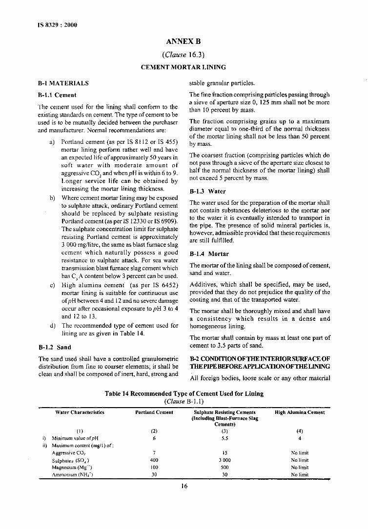
Table 14 Recommended Type of Cement Used for Lining (Clause B- 1.1)
Water Characteristics Portland Cement Sulphate Resisting Cements High Alumina Cement (Including Blast-Furnace Slag
Cements)
(I) (2) (3) (4) i) Minimum value ofpH 6 5.5 4
ii) Maximum content (mg/l) of:
Aggressive CO, 7 15 No limit
Sulphates (SO,) 400 3 000 No limit
Magnesium (Mg”) 100 500 No limit
Ammonium (NHI*) 30 30 No limit
16
which could be detrimental to goodcontract between the metal and the lining shall be removed from the surface to which the lining is to be applied.
The inner surface of pipe shall also be free of any metal projections likely to protrude beyond 50 percent the thickness of the lining.
B-3 APPLICATION OF THE LINING
The cement mortar lining at works is applied by a centrifugal spinning processor a centrifuged sprinkler or a combination of both methods.
Apart from the inner surface of the joint, the parts of the pipe coming into contact with the transported water shall be entirely covered with mortar.
Once centrifuging is finished, the lining shall be cured at temperatures greater than 4°C. Any loss of water from the mortar by evaporation shall be sufficiently slow so that hardening is not impeded.
B-4 REPAIR OF LINING
Repairs to damaged or defective areas are allowable. The damaged mortar shall first be removed from these areas. Then the defective part shall be repaired by using, for example, a trowel with fresh mortar so that a continuous lining having a constant thickness is again obtained.
For the repair operation, the mortar shall have a suitable consistency, if necessary, additives may be included to obtain good adhesion against the side of the existing undamaged mortar.
B-5 THICKNESS OF THE LINING
The normal thickness of the lining and the minimum permissible mean and local values are given in the Table 15.
At the pipe ends, the lining may be reduced to values below the minimum thickness. The length of the chamfer shail be as small as possible but, in any case, shall be less than 50 mm.
B-6 DETERMINATION OF LINING THICKNESS
The thickness of the lining is checked on the freshly centrifuged mortar by the insertion of a steel pin, or on the hardened mortar by means~of a non-destructive method of measurement. The thickness of the lining shall be measured at both ends of the pipe in at least one section perpendicular to the pipe~axis.
B-7 SURFACE CONDITION OF THE HARDENED LINING
The surface of the cement mortar lining shall be uniformly smooth. Only isolated grains of sand are allowed to appear on the surface of the lining.
17
IS 8329 : 2000
The lining shall be such that it cannot be dislodged with pressure of hand and shall be free from corrugations or ridges that could reduce the thickness of the lining to less than the minimum value at one point, as specified in the Table 16.
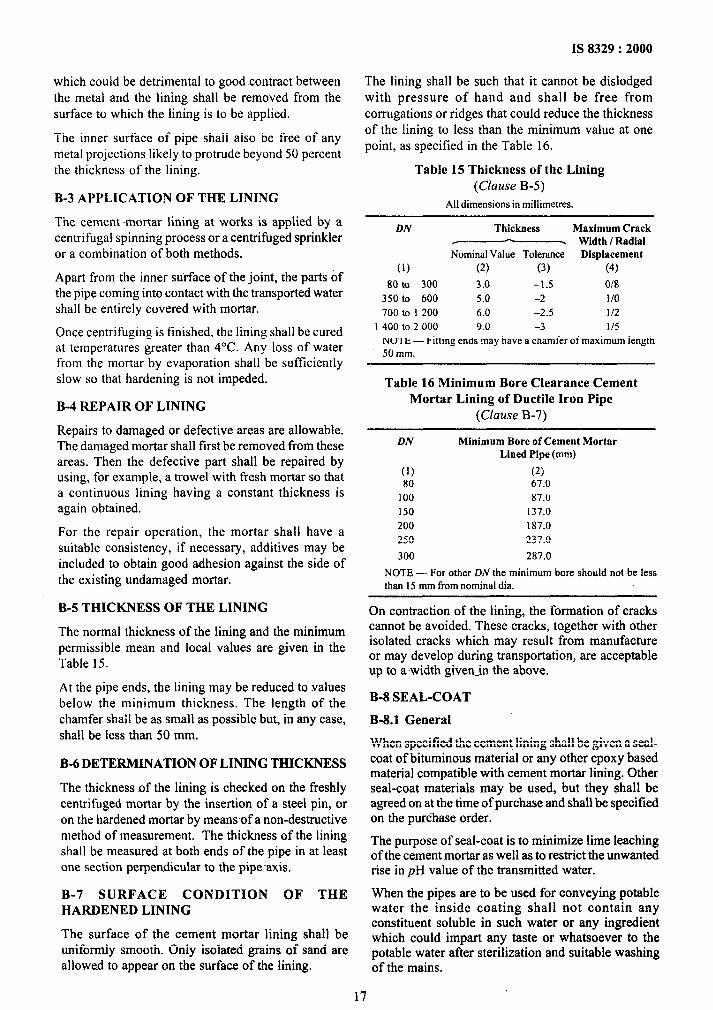
Table 15 Thickness of the Lining (Clause B-5)
All dimensions in millimetres.
DN Thickness Maximum Crack I Width I Radial
Nominal Value Tolerance Displacement
(1) (2) (3) (4)
80 to 300 3.0 -1.5 018 350 to 600 5.0 -2 l/O 700 to I 200 6.0 -2.5 l/2
I 400 to 2 000 9.0 -3 l/5 NOTE - Fitting ends may have a chamfer of maximum length 50 mm.
Table 16 Minimum Bore Clearance Cement Mortar Lining of Ductile Iron Pipe
(Clause B-7)
DN Minimum Bore of Cement Mortar Lined Pipe (mm)
(1) (2) 80 67.0
100 87.0 I50 137.0 200 187.0 250 237.0
300 287.0
NOTE - For other DIV the minimum bore should not be less than I5 mm from nominal dia.
On contraction of the lining, the formation of cracks cannot be avoided. These cracks, tagether with other isolated cracks which may result from manufacture or may develop during transportation, are acceptable up to awidth given-in the above.
B-8 SEAL-COAT
B-8.1 General
When specified the cement lining shall be given a seal- coat of bituminous material or any other epoxy based material compatible with cement mortar lining. Other seal-coat materials may be used, but they shall be agreed on at the time of purchase and shall be specified on the purchase order.
The purpose of seal-coat is to minimize lime leaching of the cement mortar as well as to restrict the unwanted rise in pH value of the transmitted water.
When the pipes are to be used for conveying potable water the inside coating .shall not contain any constituent soluble in such water or any ingredient which could impart any taste or whatsoever to the potable water after sterilization and suitable washing of the mains.
IS 8329 : 2000
ANNEX C
(Clause 16.2)
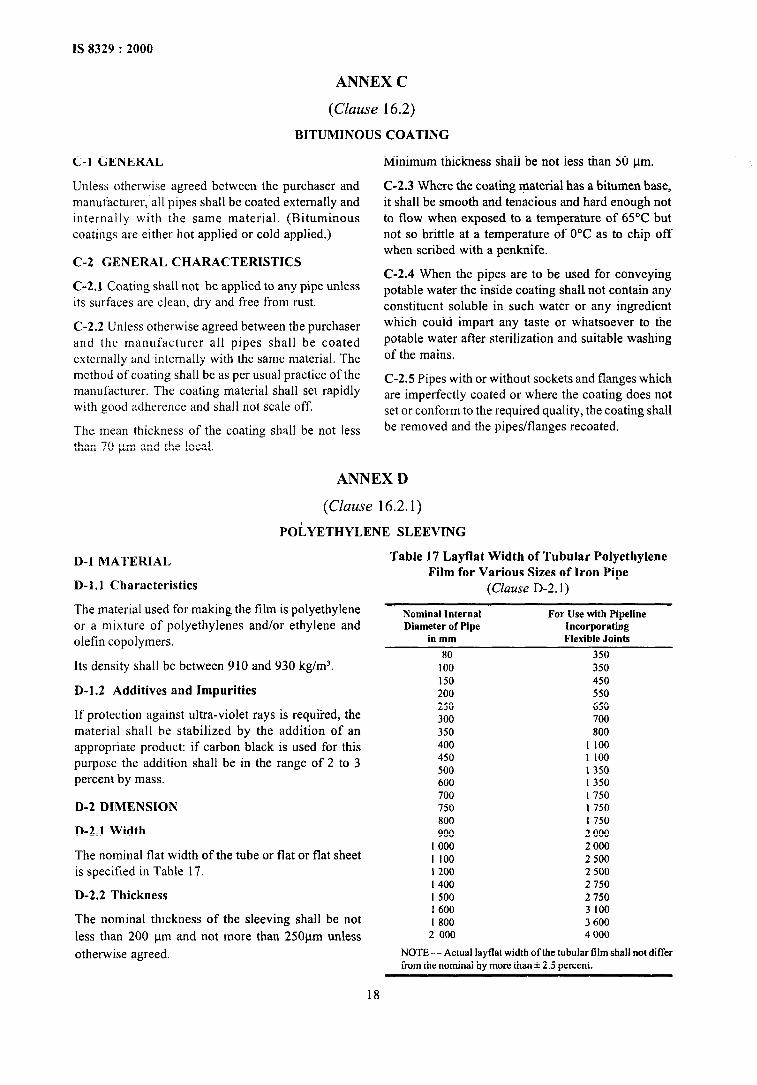
BITUMINOUS COATING
Unless otherwise agreed between the purchaser and manufacturer, all pipes shall be coated externally and internally with the same material. (Bituminous coatings are either hot applied or cold applied.)
C-2 GENERAL CHARACTERISTICS
C-l GENERAL Minimum thickness shall be not less than 50 l_tm.
C-2.3 Where the coating material has a bitumen base, it shall be smooth and tenacious and hard enough not to flow when exposed to a temperature of 65°C but not so brittle at a temperature of 0°C as to chip off when scribed with a penknife.
C-2.4 When the pipes are to be used for conveying potable water the inside coating shall not contain any constituent soluble in such water or any ingredient which could impart any taste or whatsoever to the potable water after sterilization and suitable washing of the mains.
C-2.1 Coating shall not be applied to any pipe unless its surfaces are clean, dry and free from rust.
C-2.2 Unless otherwise agreed between the purchaser and the manufacturer all pipes shall be coated externally and internally with the same material. The method of coating shall be as per usual practice of the manufacturer. The coating material shall set rapidly with good adherence and shall not scale off.
The mean thickness of the coating shall be not less than 70 ym and the local.
C-2.5 Pipes with or without sockets and flanges which are imperfectly coated or where the coating does not set or conform to the required quality, the coating shall be removed and the pipes/flanges recoated.
ANNEX D
(Clause 16.2.1)
POLYETHYLENE SLEEVING
D-l MATERIAL
D-l.1 Characteristics
The material used for making the film is polyethylene or a mixture of polyethylenes and/or ethylene and olefin copolymers.
Its density shall be between 910 and 930 kg/m3.
D-l.2 Additives and Impurities
Table 17 Layflat Width of Tubular Polyethylene Film for Various Sizes of Iron Pipe
(Clause D-2.1)
Nominal lnternal For Use with Pipeline Diameter of Pipe Incorporating
in mm Flexible Joints
80 350 100 350 150 450 200 550
If protection against ultra-violet rays is required, the material shall be stabilized by the addition of an appropriate product: if carbon black is used for this purpose the addition shall be in the range of 2 to 3 percent by mass.
D-2 DIMENSION
250 300 350 400 450 500 600 700 750
D-2.1 Width
650 700 800
I 100 1 100 1 350 I 350 I 750 I 750 I 750 2 000
800 900
I 000 2 000 I 100 2 500 I 200 2 500 I 400 2 750 I 500 2 750 1 600 3 100 I 800 3 600
2 000 4000
NOTE - Actual layflat width of the tubular film shall not differ from the nominal by more than f 2.5 percent.
The nominal flat width of the tube or flat or flat sheet is specified in Table 17.
D-2.2 Thickness
The nominal thickness of the sleeving shall be not less than 200 and not pm more than 25Opm unless
otherwise agreed.
18
IS 8329 : 2000
The negative tolerance on the nominal thickness shall not exceed 10 percent.
D-4 ELONGATION
The elongation at fracture of the film in the
longitudinal and transverse directions shall be not less than 300 percent.
D-5 DIELECTRIC STRENGTH
The dielectric strength of the film should be 3 1.5 V/pm
minimum.
If necessary, it is permitted to use thicker sleeving or
double sleeving.
D-3 MECHANICAL PROPERTIES
Tensile strength of the film in the longitudinal and
transverse direction shall be not less than 8.3 MPa.
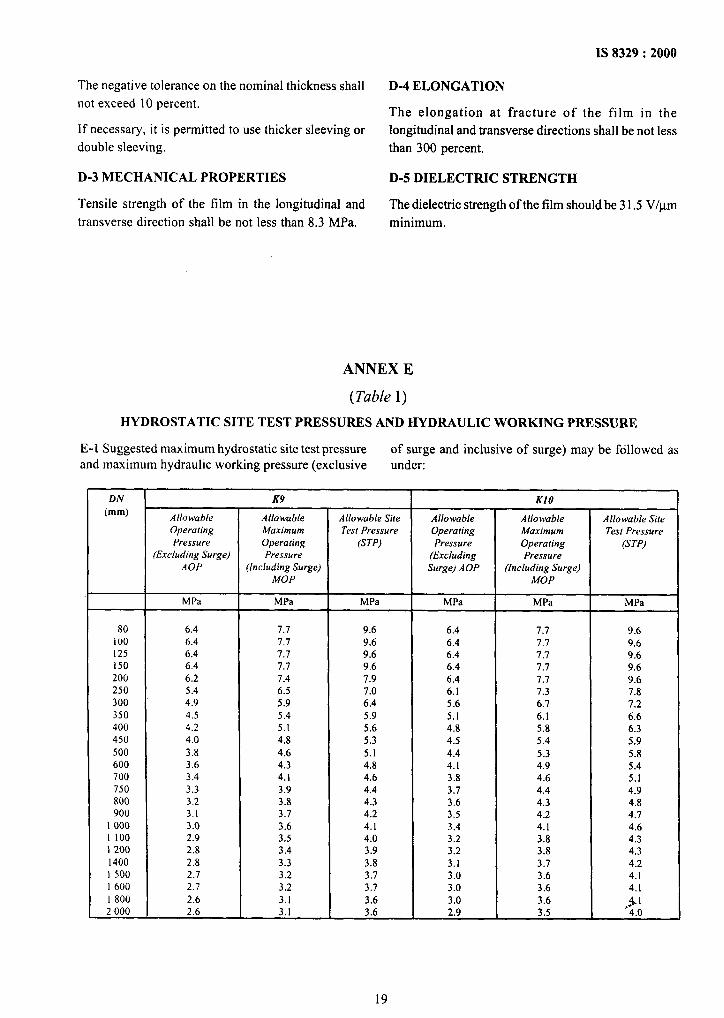
ANNEX E
(Table 1)
HYDROSTATIC SITE TEST PRESSURES AND HYDRAULIC WORKING PRESSURE
E-l Suggested maximum hydrostatic site test pressure of surge and inclusive of surge) may be followed as and maximum hydraulic working pressure (exclusive under:
DN (mm) Allowable
Operating Pressure
K9
Allowable Maximum Operating
Allowable Site Test Pressure
(STP)
Allowable Operating Pressure
KIO
Allowable Maximum Operating
Allowable Site Test Pressure
(STP) (Excluding Surge) Pressure (Excluding Pressure
AOP (including Surge) Surge) AOP (Including Surge) MOP MOP
MPa MPa MPa MPa MPa MPa
80 6.4 7.1 9.6 6.4 7.7 9.6
100 6.4 7.7 9.6 6.4 7.7 9.6
125 6.4 7.7 9.6 6.4 7.7 9.6
150 6.4 7.7 9.6 6.4 7.7 9.6
200 6.2 1.4 7.9 6.4 1.7 9.6 250 5.4 6.5 1.0 6.1 7.3 7.8 300 4.9 5.9 6.4 5.6 6.7 7.2
350 4.5 5.4 5.9 5.1 6.1 6.6
400 4.2 5.1 5.6 4.8 5.8 6.3
450 4.0 4.8 5.3 4.5 5.4 5.9
500 3.8 4.6 5.1 4.4 5.3 5.8
600 3.6 4.3 4.8 4.1 4.9 5.4
700 3.4 4.1 4.6 3.8 4.6 5.1
750 3.3 3.9 4.4 3.7 4.4 4.9
800 3.2 3.8 4.3 3.6 4.3 4.8 900 3.1 3.1 4.2 3.5 4.2 4.7
I 000 3.0 3.6 4.1 3.4 4.1 4.6
I 100 2.9 3.5 4.0 3.2 3.8 4.3
1 200 2.8 3.4 3.9 3.2 3.8 4.3
I400 2.8 3.3 3.8 3.1 3.7 4.2
1 500 2.7 3.2 3.7 3.0 3.6 4.1
I 600 2.7 3.2 3.7 3.0 3.6 4.1
1 800 2.6 3.1 3.6 3.0 3.6 1 2 000 2.6 3.1 3.6 2.9 3.5 ,d- 4.0
19
(Continuedfrom second cover)
ISO/DIS 10803 : 1997(E)
ISO/DIS 10804:Part-l/l994
EN 545 : 1994
EN 598 : 1995
EN 969 : 1996
Design method for ductile iron pipes
Restrained joint system for ductile iron pipelines: Part 1 Design rule and type testing
Ductile iron pipes, fittings accessories and their joints for water pipelines.
Ductile iron pipes, fittings, accessories and their joints for sewerage applications
Ductile iron pipes, fittings, accessories and their joints for gas pipeline
For the purpose of deciding whether a particular requirement of this standard is complied with, the. final value, observed or calculated, expressing the result of a test, shall be rounded off in accordance with IS 2 : 1960 ‘Rules for rounding~off numerical values (revised)‘. The number of significant places retained in the rounded off value should be the same as that of the specified value in this standard.
,_ ..,_-. ________.._.__ _. _ .--.__
Bureau of Indian Standards
BIS is a statutory institution established under the Bureau of Indian Standards Act, 1986 to promote harmonious development of the activities of standardization, marking and quality certification of goods and attending to connected matters in the country.
Copyright
BlS has the copyright of all its publications. No part of these publications may be reproduced in any form without the prior permission in writing of BIS. This does not preclude the free use, in the course of implementing the standard, of necessary details, such as symbols and sizes, type or grade designations. Enquiries relating to copyright be addressed to the Director (Publications), BIS.
Review of Indian Standards
Amendments are issued to standards as the need arises on the basis of comments. Standards are also reviewed periodieally; a standard along with amendments is reaffirmed when such review indicates that no changes are needed; if the review indicates that changes are needed, it is taken up for revision. Users of Indian Standards should ascertain that they are in possession of the latest amendments or edition by referring to the latest issue of ‘BIS Catalogue’ and ‘Standards: Monthly Additions’.
This lndian Standard has been developed from Dot : No. MTD 6 (4227).
Amendments Issued Since Publication
Amend No. Date of Issue Text Affected
BUREAU OF INDIAN STANDARDS
Headquarters :
Manak Bhavan, 9 Bahadur Shah Zafar Marg, New Delhi 110 002 Telegrams : Manaksanstha Telephones : 323 01 3 I, 323 33 75,323 94 02 (Common to all offices)
Regional Offices : Telephone
Central : Manak Bhavan, 9 Bahadur Shah Zafar Marg 323 76 17 NEW DELHI 110 002 323 38 41
Eastern : l/l 4 C. I. T. Scheme VII M, V. I. P. Road, Kankurgachi 337 84 99,337 85 61 CALCUTTA 700 054 337 86 26,337 91 20
Northern : SC0 335-336, Sector 34-A, CHANDIGARH 160 022 { 60 38 43 60 20 25
Southern : C. 1. T. Campus, IV Cross Road, CHENNAI 600 113 { 235 02 16,235 04 42 235 15 19,235 23 15
Western : Manakalaya, E9 MIDC, Marol, Andheri (East) 832 92 95,832 78 58 MUMBAI 400 093 { 832 78 91,832 78 92
Branches : AHMADABAD. BANGALORE. BHOPAL. BHUBANESHWAR. COIMBATORE. FARIDABAD. GHAZIABAD. GUWAHATI. HYDERABAD. JAIPUR. KANPUR. LUCKNOW. NAGPUR. PATNA. PUNE. RAJKOT. THIRUVANANTHAPURAM.
Printed at Dee Kay Printers, New Delhi
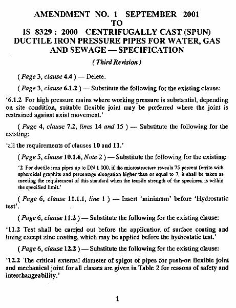
AMENDMENT NO. 1 SEPTEMBER 2001
IS 8329: 2000 CENT%JGALLY CAST (SPUN)DUCTILE IRON PRESSURE PIPES FOR WATER, GAS
AND SEWAGE — SPECIFICATION
( Third Revision)
(Page 3, clause 4.4) — Delete.
(Page 3, clause 6.1.2) — Substitute the following for the existing clause:
‘6.1.2 For high pressure mains where working pressure is substantial, dependingon site condition, suitable flexible joint may be preferred where the joint isrestrained against axial movement.’
( Page 4, clause 7.2, lines 14 and 15 ) — Substitute the following for theexisting:
‘all the requirements of clauses 10 and 11.’
(Ppge 5, clause 10.1.6, IVole 2 ) — Substitute the following for the existing
‘2 For ductile iron pipes up (o DN 1 COO,if the microstructure reveals 75 percent ferrite withspheroidal grapfrite and percentage elongation higher than or equal to 7, it shall be taken asmeeting the requirement of this standard when the tensile strength of the specimen is withinthe specified limit.’
( Page 6, clause 11.1.1, line 1 ) — Insert ‘minimum’ before ‘Hydrostatictest’.
(Page 6, clause 11.2) — Substitute the following for the existing clause:
‘11.2 Test shall be carr@i out before the application of surface coating andlining except zinc coating, which may be applied before the hydrostatic test.’
(Page 6, clause 12.2) — Substitute the following for the existing clause
‘12.2 The critical external diameter of spigot of pipes for push-on flexible jointand mechanical joint for all classes are given in Table 2 for reasons of safety andinterchangeability.’
1
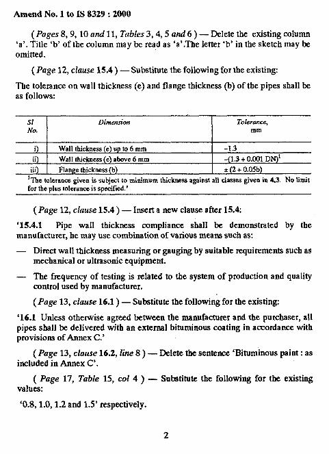
Amend No. 1 to IS 8329:2000
(Pages 8,9,10 and 11, Tables 3,4,5 and 6 ) – Delete the existing column‘a’. Title ‘b’ of the column maybe read as ‘a’.The letter ‘b’ in the sketch may beomitted.
(Page 12, clause 15.4 ) — Substitute the following for the existing
The tolerance on wall thickness (e) and flange thickness (b) of the pipes shall beas follows:
S1 Dimension Tolero~ce,No. mm
i Wall thickness (e) up to 6 mm -1.3
ii) Wall thickness (e) above 6 mm -(1.3 + 0.001 DN)*.,.111 Flange thickness (b) *(2 + 0.05b)
Ine IoleraRWgiven is subj~t to ~i~mum thickness against all cl- given in 4.3. NO‘tit
for the plus tolerance is specified.’
(Page 12, clause 15.4 ) — Insert a new clause after 15.4:
‘15.4.1 Pipe wall thickness compliance shall be demonstrated by themanufacturer, he may use combination of various means such as:
— Direct wall thickness measuring or gauging by suitable requirements such asmechanical or ultrasonic equipment.
— The frequency of testing is related to the system of production and qualitycontrol used by manufacturer,
(Page 13, clause 16.1 ) — Substitute the following for the existing:
‘16.1 Unless otherwise agreed betsveen the manufacturer and the purchaser, allpipes shall be delivered with an external bituminous coating in accordanrx withprovisions of Annex C.’
(Page 13, clause 16.2, line 8) — Delete the sentence ‘Bituminous paint: asincluded in Annex C’.
( Page 17, Table 15, CO14 ) — Substitute the following for the existingvalues:
‘0.8, 1,0,1.2 and 1.5’ respectively.
2
Amend No. 1 to IS 8329:2000
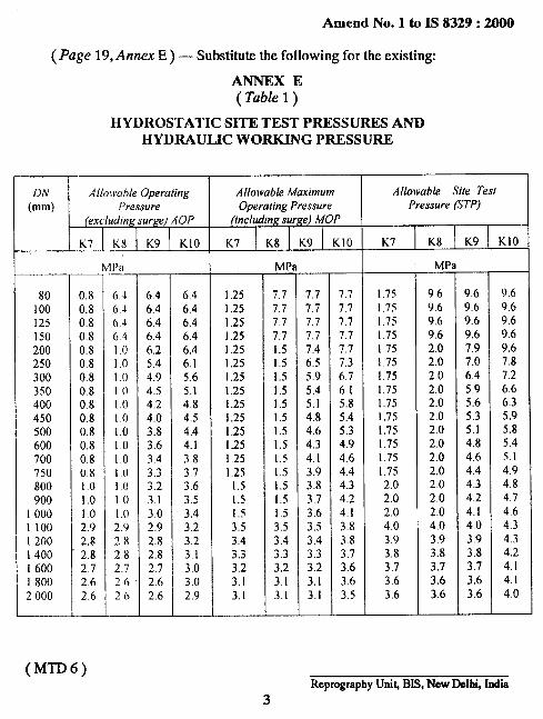
(Page 19, Amex E) — Substitute the following for the existing
ANNEX E( Table 1 )
HYDROSTATIC SITE TEST PRESSURES ANDHYDRAULIC WORKING PRESSURE
80100125150200250300350400450500600700750800900
1000110012001400I 60018002000
0.80.80.80.80.80.80,80.80.80.80.80.80.80.81.01.01.02.92.82.82,72.62.6
(MTD6)
1’21
6-I646.46.4I.01.01.()I .0i .()I ,01.()10LoI o101.()102.92x2.82.72626
6.46.46.46.46.25.44.94.54.24.03.83.63.43.33.23.13.02,92.82.82.72.62.6
—
6,46.46.46.46,46.15.65.14.84.54.44.13.8373.63,5
3.43.23.23.13.03.02.9
Allowable MaximumOperating Pressure
(including surge) MOP1 ! I
K71K8\K9 KIO
1.251,251.251.251.251.25I,251.251.251,251.251.251.251.25
1.51.5I.53.53.43.33.23.13.1
MPa
17.77.77.77.71.51.51.51.5I.51,5I .51,51,51.5I.51.5I .53.53.43.33,23.13.1
7.77.77.77.77.46.55.95.45.14.84.64.34,13.93.83.73.63,53.43.33.23.13,1
—
7.77.77.77.77.77.36.76. I5.85.45.34.94.64,44.34.24.13.83.83.73.63.63.5
Allowable Site TestPressure (STP)
K7 KS K9 K1O
1.751.75I.75I.75i .751.751.751.751.751,751.751,75[.75I.752.02.02.04.03,93.83.73.63.6
MP
969.69.69.62.02.02.02.02.02.02.02.02.02.02.02.02.04.03.93.83.73.63.6
1?.6?.69.69,6 :7.97.06.45.95.65.35.14.84.64,44,34.24.1403.93.83.73,63.6
—
Reprography Unih BIS, New Delhi, Idla3
—
9.69.69.69.69.67.87.26.66.35.95.85,45.I4.94.84.74.64.34.34.24. I4.14.0
1
.- —..
—— .—.
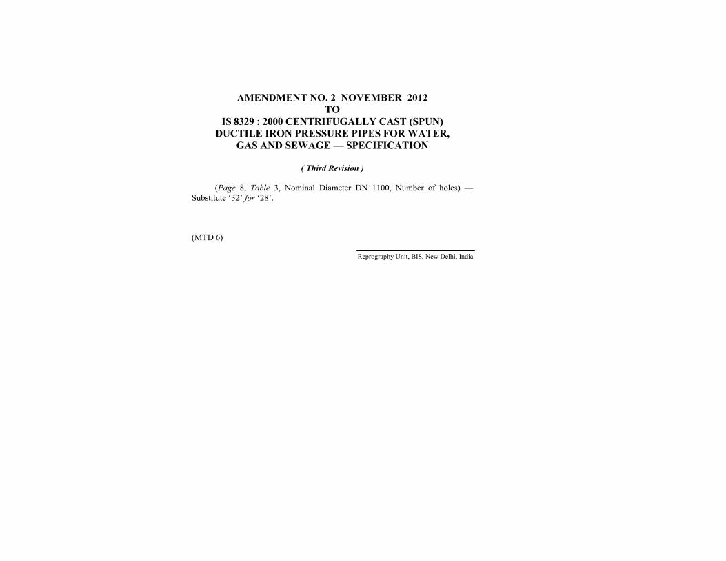
AMENDMENT NO. 2 NOVEMBER 2012TO
IS 8329 : 2000 CENTRIFUGALLY CAST (SPUN)DUCTILE IRON PRESSURE PIPES FOR WATER,
GAS AND SEWAGE — SPECIFICATION
( Third Revision )
(Page 8, Table 3, Nominal Diameter DN 1100, Number of holes) —Substitute ‘32’ for ‘28’.
(MTD 6)
Reprography Unit, BIS, New Delhi, India