is: 8009 indian statidard - e-library wcl : 8009 ( part ii ) - 1980 (continuedfrom pase 1) members...
TRANSCRIPT
IS: 8009 (Part II)-1980
Indian Statidard CODE OF PRACTICE FOR
CALCULATION OF SETTLEMENT OF FOUNDATIONS
PART II DEEP FOUNDATIONS SUBJECTED TOSYMMETRICAL STATIC VERTICAL LOADING
( Second Reprint SEPTEhlBER 1992 )
UDC 624.15:624.131.526:006.76
@ Copvighf 198 ‘1
BUREAU OF INDIAN STANDARDS MANAK BHAVAN, 9 BAHADUR SHAH ZAFAR MARG
NEWDELHI
October 198 1
IS: 8009 (Part II)-1980
Indian Standard CODE OF PRACTICE FOR
CALCULATION OF SETTLEMENT OF FOUNDATIONS
PART II DEEP FOUNDATIONS SUBJECTED TO SYMMETRICAL STATIC VERTICAL LOADING
Foundation Engineering Sectional Committee, BDC 43
Chairman Representing
PROP DIN&~ MOUAN CentraaorE$ding Research Institute (CSIR).
Members
DR R. K, BHANDAR~ Cent;Aorlzzding Research Institute (CSIR),
CHIEF ENGINEER Calcutta Port Trust, Calcutta SHRI S. GUHA (Alternate)
SHRI M. G. DANDAVATE The Concrete Association of India, Bombay SHRI RI. C. DUGGAL (Alternate)
SHRI A. G. DASTIDAR In personal capacity (5, Hungerford Road, 221,
SHRI V. C. DESHPANDE Hungerford Street, Calcutta)
DIRECTOR (CSMRS) The Pressure Piling Co (I) Pvt Ltd, Bombay Central Water Commission, New Delhi
DEPUTY DIRECTOR (CSMRS) (Alternate) SHRI A. H. DIVANJI Asia Foundations and Construction Co Pvt Ltd,
Bombay SHRI A. N. JANGLE (Alternate)
DR R. K. DAS GUPTA Simplex Concrete Piles (India) Pvt Ltd, Calcutta ADDITIONAL CHIEF ENGINEER (A&nate)
DR JACDISH NARAIN In&an Geotechnic Society, New Delhi
SHRI PROF SWAMI SARAN (Alternate) 0. S. JAIN G. S. Jain & Associates, Roorkee
SHRI ASHOK KUMAR JAIN (Afternate) JOINT DIRECTOR (D)
SHRI SUNIL BERY (Alternate) National Buildings Organis’ation, New Delhi
JO~~~~UCTOR RESEARCH (SM), Ministry of Railbays
Jonrr DIRECTOR RESEARCH (B & S),XDSO (Alternate)
DR R. K. KATTI Indian Institute of Technology, Bombay
(Continued on page 2)
0 Copyright 1981
BURJ%U OF INDIAN STANDARDS
This publication is protected under the Indian Copyrikht Act (XIV of 1957) and reproduction in whole or in part by any means except with written permission of the publisher shall be deemed to be an infringement of copyright under the said Act.
IS : 8009 ( Part II ) - 1980
(Continuedfrom pase 1)
Members Representing
SHRI S. R. KULKARNI SHRI S. ROY (A~fernate)
SHRI 0. P. MALHOTRA SHRI V. B. MATHUR SARI A. P. MATHUR SHRI T. K. D. MIJNSI
SARI M. IYENOAR (Ahnate) SHRI B. K. PA?ITFIAKY.
M. N. Dastur & Co Pvt Ltd, Calcutta
Public Works Department, Chandigarh Mckenzies .Limited, Bombay Central Warehousmg Corporation, New Delhi Engineers India Limited, New Delhi
SARI V. M. MADCE (Alternate) SHRI M. R. PUNJA
SHRI S. MUKHERJEE (Alternate) SHRI N. E. V. RA~HVAN
The Hindustan Construction Company Limited, Bombay
Cemindia Co Ltd, Bombay
The Braithwaite Burn & Jessop Construction CO Ltd, Calcutta
SHRI A. A. RAJU PROF GOPAL RANJAN SHRI T. N. SUBBA RAO
SHRI S. A. REDDI (Alternate) SHRI.Y. V. NARASIMHA RAO
Vijayanagar Steel Plant (SAI), New Delhi University of Roorkee, Roorkee Gammon India Limited, Bombay
Bokaro Steel Plant (Steel Authority of India), Bokaro
DR V. V. S. RAO ” . - Nagadi Consultants Pvt Ltd, New Delhi Cement Corporation of India, New Delhi 3HRI ARJUN KIJHSINCHANI
SHRI 0. S. SRIVASTAVA (Ahernate) RR A. SARG~NAN
SHRI S. BOOMINATHAN (Alternate) College of Engineerin_g, Guindy, Madras
SHRI K. R. SAXENA Public Works Department, Government of Andhra
DR S. P. SHRIVASTAVA Pradesh, Hyderabad
United Technical Consultants Pvt Ltd, New Delhi DR R. KAPUR (Alternate)
BRIG OMBIR SINCH Engineer-in-Chief’s Branch, Army Headquarters, New Delhi
MAJ H. K. BHUTANI (Alternate) SHRI N. SIVA~URU
SHRI D. V. SIKKA (Alternate) Ministry of Shipping and Transport, New Delhi
SUPERINTENDING ENGINEER (DESIONS) Central Public Works Department, New Delhi EXECIJTIVE ENGINEER (DESIGNS) V
(AlhYla6e) SHRI M. D. TAMBEKAR DR A. VARADARAJAN
DR R. KAN~AJ (Alternate) SHRI G. RAMAN,.
Director (Clvd Engg)
Bombay Port Trust, Bombay Indian Institute of Technology, New Delhi
Director General, IS1 (Ex-oj?cio Member)
SecWasy
SHRI K. M. MATHUR Deputy Director (Civil Engg), IS1
Pile Foundations Subcommittee, BDC 43: 5
Convener
SHRI M. D. TAMBEKAR Bombay Port Trust, Bombay
(Continued on pap 20)
i ?A
4
0.1 on Set co
0.2 Of
t w to
0. in lil
1 P’ m
2
IS: 8009 (Part II)-1980
Indian Standard _
CODE OF PRACTICE FOR CALCULATION OF SETTLEMENT OF
FOUNDATIONS PART II DEEP FOUNDATIONS SUBJECTED TO SYMMETRICAL
STATIC VERTICAL LOADING
0. FOREWORD
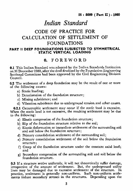
0.1 This Indian Standard was adopted’by the Indian Sta.ndards Institution on 3 1 December 1980, after the draft finalized by the Foundation Engineering Sectional Committee had been approved .by the Civil Engineering Division Council.
0.2 The settlement of a deep foundation may be the result of one or more of the following causes:
a) Static loading; b) Deterioration of the foundation structure; c) Mining subsidence ; and d) Vibration subsidence due to underground erosion and other causes.
03.1 Catastrophic settlement may occur if the static load is excessive. When the static load is not excessive, the resulting settlement may be due to the following:
4 b) 4
4 e> f 1
d
Elastic compression of the foundation structure; Slip of the foundation structure relative to the soil; Elastic deformation or immediate settlement of the surrounding soil and soil below the foundation structure; Primary consolidation settlement of the surrounding soil; Primary consolidation settlement of the soil below the foundation structure; Creep of the foundation structure under the constant axial load; and Secondary compression of the surrounding soil and soil below the foundation struoture.
0.3 If a structure settles uniformly, it will not theoretically suffer damage, irrespective of the amount of settlement. But, the underground utility lines may be damaged due to excessive settlement of the structure. In practice, settlement is generally non-uniform. Such non-uniform settle- ments induce secondary stresses in the structures. Depending upon the
IS t 8009 (Part II)-1980
permissible extent of these secondary stresses, the settlements have to be limited. Alternatively, if the estimated settlements exceed the allowable limits, the foundation dimensions or the design may have to be suitably modified. Therefore, this Code is prepared to provide a common basis, to the extent possible, for the estimation of the settlement of foundations subjected to symmetrical static vertical loading. The Code is in two parts: Part I deals with shallow foundations. This Part II deals with deep foundation. Part I is complimentary to this part.
0.4 A settlement calculation involves many simplifying assumptions as detailed in 4.1. In the present state of knowledge, the settlement compu- tations at best estimate the most probable magnitude of settlement.
0.5 For the purpose of deciding whether a particular requirement of this standard is complied with, the final value, observed or calculated, ex- pressing the result of‘s test or analysis, shall be rounded off in accordance with IS: 2-1960*. The number of significant places retained in the rounded off value should be the same as that of the specified value in this standard.
1. SCOPE
1.1 This Standard (Part II) provides simple methods for the estimation of elastic compression of the foundation structure, immediate and primary consolidation settlements of deep foundations under symmetrical static vertical loads. In addition, procedures for computing time rate of settle- ment are also given.
1.2 In this standard, it is presumed that the load on the foundation will be limited to safe bearing capacity and therefore catastropic settlements are not expected; Settlement due to deterioration of foundations, mining and other causes cannot, in the present state of knowledge, be estimated. Even though, it is known that inorganic clays and plastic silts, secondary compres- sion plays an important part, satisfactory theoretical methods are not avail- able. Such methods are not alsot available for computation of settlement due to the slip of foundation structure with reference to the surrounding soils and creeping of foundation structure and therefore not covered in this code.
2. TERMINOLOGY
2.0 For the purpose of this standard, the definitions of terms given in Part I of this code, IS: 2911 (Part I/Set l)-1979t, IS: 2809-1972$, IS: 3955-1967$ and the following shall apply.
- *R&s for rounding off numerical values (fevkxf). tcodc of practice for design and construction of pile foundations: Part I Concrete piles,
Section I Driven cast in-situ piles (j&f PX.JZ&J~Z). f~lossary of terms and symbols relating to soil engineering (Jirst revlion). @ode of practice for design and construction of well foundations.
4
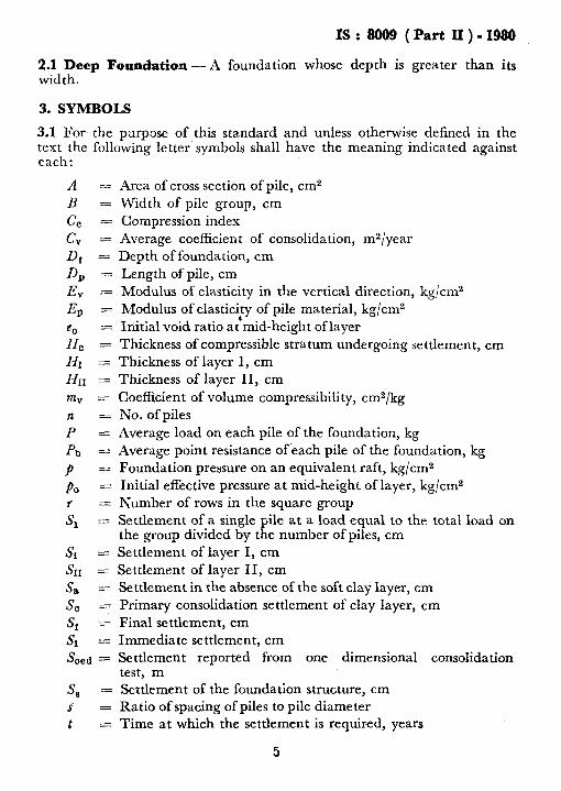
3.1 For the purpose of this standard and unless otherwise defined in the text the following letter symbols shall have the meaning indicated against each:
A =
B =
c, = c, = Df = D, = Ev = Ep =
y$ :
HI =
HII = m, = n zzz
P =
Pb =
P =
PO =
6 z
Area of cross section of pile, cm2
Width of pile group, cm Compression index Average coefficient of consolidation, m2/year Depth of foundation, cm
Length of pile, cm Modulus of elasticity in the vertical direction, kg/cm2 Modulus of elastici,ty of pile material, kg/cm2 Initial void ratio at mid-height of layer Thickness of compressible stratum undergoing settlement, cm Thickness of layer I, cm Thickness of layer II, cm
Coefficient of volume compressibility, cm2/kg No. of piles
Average load on each pile of the foundation, kg Average point resistance ofeach pile of the foundation, kg Foundation pressure on an equivalent raft, kg/cm2 Initial effective pressure at mid-height of layer, kg/cm2 Number of rows in the square group Settlement of a single the group divided by t B
ile at a~load equal to the total load on e number of piles, cm
Sr =
&I =
s, =
SC =
Sf =
L!$ =
S oed =
Settlement of layer I, cm Settlement of layer II, cm Settlement in the absence of the soft clay layer, cm Primary consolidation settlement of clay layer, cm
Final settlement, cm Immediate settlement, cm Settlement reported from one dimensional consolidation test, m
s, = s‘ =
t =
Settlement of the foundation structure, cm Ratio of spacing of piles to pile diameter Time at w-hich the settlement is required, years
IS: 8009 (Part II)-1980
2.1 Deep Foundation-A foundation whose depth is greater than its width.
3. SYMBOLS
5
1s : 8009 ( Part II ) - 1980
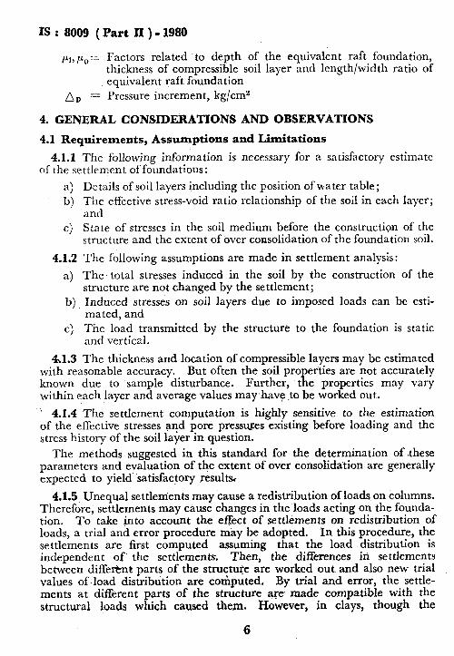
t_li, kb,,= Factors related .to depth of the equivalent raft foundation, thickness of compressible soil layer and length/width ratio of equivalent raft foundation
n, = Pressure increment, kg/cm2
4. GENERAL CONSIDERATIONS AND OBSERVATIONS
4.1 Requirements, Assumptions and Limitations
4.1.1 The following information is necessary for a satisfactory estimate of the settlement of foundations:
a) Details of soil layers including the position of water table; b) The effective stress-void ratio relationship of the soil in each Iayer;
and c) State of stresses in the soil medium before the construction of the
structure and the extent of over consolidation of the foundation soil.
4.1.2 The following assumptions are made in settlement analysis:
a) The total stresses induced in the soil by the construction of the structure are not changed by the settlement;
b) Induced stresses on soil layers due to imposed loads can be esti- mated, and
c) The load transmitted by the structure to the foundation is static and vertical.
Al.3 The thickness and location of compressible layers may be estimated with reasonable accuracy. But often the soil properties are not accurately known due to sample disturbance. Further, the properties may vary within each layer and average values may-have to be worked out.
’ 4.1.4 The settlement computation is highly sensitive to the estimation of the effective stresses and pore presstnzes existing before loading and the stress history of the soil layer in question.
The methods suggested in this standard for the determination of .these parameters and evaluation of the extent of over consolidation are generally expected to yield satisfactory results
4.1.5 Unequal settlements may cause a redistribution of loads on columns. Therefore, settlements may cause changes in the loads acting on the founda- tion. To take into account the eaect of settlements on redistribution of loads, a trial and error procedure may be adopted. In this procedure, the settlements are first computed assuming that the load distribution is independent of the settlements. Then, the differences in settlements between different parts of the structure are worked out and also new trial values of load distribution are computed. By trial and error, the settle- ments at different parts of the structure are made compatible with the structural loads which caused them. However, in clays, though the
6
settl due
4 CUSl
the1
4.2
4 ing
. oft1
4. of cc
4 fou
4 wh imt me COf car sun usil
4.3 Fol
a 4
del. loac
i tyP1 sevt
vel the
IS : 8009 ( Part II ) - 1980
settlements often occur over long periods, the readjustment of column loads due to creep in structural materials are often not taken note of.
4.1.6 The soil layers experience stresses due to the imposed loads. It is customary to compute stresses induced in soil by simple formulae based on theory of elasticity or by approximate methods.
4.2 Soil Profile
4.2.1 The soil profile may be simplified into one or more layers depend- ing upon the extent of uniformity. The settlement is computed 7-s the sum of the settlements of all layers which are affected by the superimposed loads.
4.2.2 The following are the possible types of soil formations for purposes of computing the settlements of deep foundations:
a) Homogeneous cohesionless deposit, b) Homogeneous cohesive soil deposit, c) Deposit of two or more regular soil layers, d) Erratic soil deposit, and e) Thin soil deposit resting on rock.
4.2.3 Rock is imcompressible compared to soil and therefore, if the foundation rests on soil, the settlement of rock stratum is neglected.
4.2.4 Sands and other cohesionless soils undergo settlement immediately; whereas clays undergo immediate and consolidation settlements. The immediate settlement can be estimated by pile load tests and by theoretica,l methods, using elastic constants obtained from undrained tests. The consolidation settlements are estimated by approximate methods using the consolidation test results. The total settlements can be estimated a.s the sum of immediate and consolidations settlements or by theoretical methods using the elastic constants obtained from drained tests.
4.3 General Observatians on Computation. of Settlements of Deep Foundations
4.3.1 The methods of estimating the settlement of deep foundations depend upon the type of deep foundation and the manner of transfer of loads from the foundation structure to the foundation soil apart from the type of soil profile. Therefore, the methods given are grouped under several heads, depending upon these factors.
NOTE - In the present state of kno&dge, &en the methods available for estimating total settlementq are in a developing stage and therefore no reference is made to diffkrential settelements im this standard.
4.3.2 The theoretical estimation of settlement is done by integrating the vertical strain for the entire depth of soil or rock formation. the theoretical method is tedious, other procedures are adopted.
In general
7
IS : 8009 ( Part II ) - 1980
5. STEPS INVOLVED IN SETTLEMENT COMPUTATIONS
5.1 The following are the necessary steps in settlement analysis:
a) Collection of relevant information,
b) Determination of subsoil profile,
c) Stress analysis,
d) Estimation of settlements, and
e) Estimation of time rate of settlements.
6. COLLECTION OF RELEVANT INFORMATION
6.1 The following details pertaining to the proposed structure are required for a satisfactory estimation of settlements:
a)
b)
4
4
Site plan showing the location of proposed as well as neighbouring structures;
Building plan giving the deta.iled la.yout of load bearing wa.lls and columns and the dead and live loads to be transmitted to the foundation J
Other relevant details of the structure, such as rigidity of structure; and
A review of the performance of structures,,if any, in the locality and collection of data from actual settlement observation on structures in the locality.
7. DETERMINATION OF SUBSOIL PROFILE
7.1 It is required tha.t a sufficient number of borings be taken in accordance with IS: 1892-1980* to indicate the limits of various underground strata, a.nd to furnish the location of water table and water bearing strata. Generally, it will be sufficient, if twd’exploratory holes are located diago- nally on opposite corners, unless the proposed structure is small, in which case one bore hole at the centre may be sufficient. For large structures, additional bore holes may be driven suitably.
7.2 A plot of the borings is likely to show some irregularities in the various strata. However, in favoura.ble cases, all borings may be sufficiently alike to allow the choosing of an idealized profile, which differs only slightly from any individual borings and which is/a close representation of average strata characteristics.
7.3 Adequate boring data and.good judgement in the interpretation of the data are pdme requisites in the calculation of settlements. In the case of cohesionless soils, the data’ should include the results of standard
*Code of practice for subsurface investigation for foundations (first revision).
8
IS: 8009 (Part II)-1980
penetration tests (see IS: 2131-1963*). In the case of cohesive soils, the data should include consolidation test results on undisturbed samples [.w IS : 2720 (Part XV)-196Sl_]. A ccuracy of settlement calculation improves with increasing number of consolidation tests on undisturbed samples. The number of samples to be tested depends on the extent of uniformity of soil deposit and the significance of the proposed structure. In general, in the case of clay layers, for each one of the clay layers within the zone of stress influence at least one undisturbed sample should be tested for consolidation characteristics. In the case of thick clay layers, consolidation test should be done on samples collected at 2 m or lesser intervals. .
8. STRESS ANALYSIS
8.1 Initial Pore Pressure and Effective Stress 4
8.1.1 The total ‘vertica.1 pressure at any depth below ground surface is dependent only on the weight of the overlaying materials. The values of natural unit weight obtained for the sample at different depths, should be used to compute the pressures. To obtain initial effective pressure, neutral pressure values should be subtracted from the total pressure. The possible major types of preloa.ding conditions that can exist are the follow- ing (see Fig. 7 of Part I of this Code) :
a) Simple static case, b) Residual hydrostatic case, c) Artesian case, a.nd d) Overconsolidated case.
8.1.2 In simple static case and in the overconsolidated case, the neutral pressure at any depth is equal to the unit weight of water multiplied by the depth below the free water surfa.ce. In residual hydrostatic case, a condition of partial ‘consolidation under the overburden has been recently placed a.s for example in made up lands and delta deposits. In this case, the neutral’ pressure is greater than that in the previous case, since it includes hydrostatic excess pressure. If allowed sufficient time, this case would merge with the
1 static case. In the artesian case there is upward percolation of water through the clay layer due to natural or artificial cases and in addition to the hydrostatic pressure a seepage pressure acts upwa.rds and reduces the ‘effective pressure in the soil. In the pre-compressed or overconsolidated ca.se, the clay might have been subjected to a higher effective pressure in the past than exists at present. This may be due to the water table having been lower in the past than at present or due to the erosion or removal of some depth of material at the top. The identification of one of the four cases listed above for the given site conditions is essential for the satis- factory evaluation of magnitude of settlements. The detailed procedure and the implications are described in Appendix A of Part I of. this Code.
*Method of standard penetration test for soils. TMethods of test for soils: Part XV Determination of consolidation pmperties~
9
IS : 8009 (Part II ) - 1980
8.2 Pressure Increment
8.2.1 The pressure increment is defined as the difference between the initial intergranular pressure as existed in the field ‘prior to application of load and the final intergranular pressure after application of load. The following may contribute to the pressure increment:
a) Pressure transmitted to the clay by construction of buildings or by other imposed loads;
b) Residual hydrostatic excess pressures;
c) Pressure changes caused by changes in the elevation of the water ’ table above the compressible stratum; and
d) Pressure changes caused by changes in the artesian pressure below the compressible stratum.
8.2.2 The pressure increment due to imposed loads shall be determined as detailed in 8.3. The residual hydrostatic excess pressure should be estimated by the methods’ given in Appendix A of Part I of this Code. The pressure changes caused by changes in water table elevations of artesian pressures may be estimated by field observations of ground water elevations or by anticipated fluctuations in the water table or artesian pressures due to natural or man-made causes.
8.3 Pressure Ilicrement due to Superimposed Loads
8.3.1 The stresses induced by the superimposed loads on the lower strata can be determined by elastic theory or by approximate methods.
8.3.2 The pressure increments due to the loads from deep foundations are not usually calculated using the elastic theory due to the following reasons :
4
b)
4
The distribution of friction along the length of the pile or other deep foundation and the bearing load are not known;
The influence of the method and process of installation of the foundation structure are not known; and P
Va.riation in the distribution of the loads due to time dependent effects such as thixotrophy, varying loads, change in ground water, consolidation is not known.
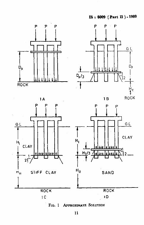
8.3.3 (see Fig. I).
In view of the foregoing, approximate methods are widely adopted _.
8.3.4 For friction pile groups it is assumed that the fictitious footing is at a depth of Da/3 above the pile tip (see Fig. 1B).
8.3.5 For point bearing pile roups the pile group is replaced by a ficti- a tious footing at the top of t e bearing layer (see Fig. IC). The load is
assumed to be uniformly distributed and spread at 2: 1 slope, or at 60” to the horizontal.
10
IS : 8009 ( Part II ) - 1980
P P P P P P
1A
I HII SliFF CLAY
/ t
/ ROCK
IC
1B ROCK
’ - - ,- CLAY
ROCK
IO
Fxb. 1 A~PROXXMATE SOLUTION
11
IS : 8889 ( Part II ) - 1980
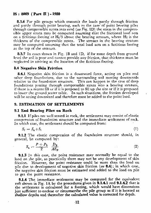
8.3.6 For pile groups which transmit the loads partly through friction and partly through point bearing, such as the case-of point bearing piles through compresslble strata into sand (see Fig. 1D) the stress in the compres- sible upper strata may be computed assummg that the frictional load acts on a fictitious footing at Ht/3 above the bearing stratum, where HI is the thickness of the compressible strata. The stresses in the bearing stratum may be computed assuming tha,t the total load acts on a fictitious footing at the top of the stratum.
8.3.7 In casts shown in Fig. 1B and ID, if for some depth from ground level the soil is poor and cannot provide any friction, that thickness must be neglected in arriving at the location of the fictitious footing.
8.4 Negative Skin Friction
8.4.1 Negative skin friction is a downward force, acting on piles and other deep foundations, due to the surrounding soil movmg downwards relative to the foundation structure. This can happen in the case of deep foundations passing through compressible strata into a bearing stratum, if there is a recent fill or if it is proposed to fill up the site or if it is proposed to lower the ground *water table. Jn such situations, the friction developed will be acting downward and therefore must be added to the point load.
9. ESTIMATION OF SETTLEMENTS
9.1 End Bearing Piles on Rock
9.1.1 If piles are well seated in rock, the settlement may consist of elastic compression of foundation structure and the immediate settlement of rock. In which case, the settlement should be computed from:
3, = S,+& (1)
9.1.2 The elastic compression of the foundation structure should, in general, be computed by:
S =P+Pb DP 8 2 AEI, (2)
9.1.3 In this case, the point resistance may normally be equal to the load on the pile, as practically there may not be any development of skin friction. However, the point resistance could be more than the load on pile due to development of negative skin friction (see 8.4); in which case, the negative skin friction must be estimated and added to the load on pile to get the point resistance.
9.1.4 The immediate settlement may be computed for the equivalent raft shown in Fig. 1A by the procedures given in 9.1.4.1 and 9.1.4.2 that is the settlement is calculated for a footing, which would have dimensions just sufficient to enclose or circumscribe the pile group as if it is located at shallow depths and thereafter the calculated value is corrected for depth.
12
IS : 8009 (Part II) - 1980
9.1.4.1 The immediate settlement beneath the centre or corner of the equivalent raft (see Fig. IA) is given by:
Si = $2 Cl ;1’2) I . .
where
E = Modulus of Elasticity,
CL = Poission’s ratio = 0.5, and
I = Influence factor (same as given in Table 2 of Part I of this Code).
9.1.4.2 The calculated settlement may be corrected for depth offounda- tion by:
Corrected Settlement .= Si x Depth factor . . (4) The Depth factor may be read from Fig. 12 of Part 1 of this Code.
9.1.5 The settlement may also be estimated from load tests. But if there is a possibility for development of negative skin friction, the same must be estimated and the settlement value obtained from the load test modified appropriately.
9.2 End Bearing Piles on Decomposed Rock
9.2.1 The compressibility of decomposed rock cannot be relia.bly esti- mated in the present state of knowledge. Settlement in this situation can be estimated largely on 1ocaI experience.
9.3 End Bearing Piles through Compressible Strata into Sand
9.3.1 The settlement of piles and pile groups through compressible strata into sand depends upon the ratio between point resistance and total load. It will be the sum of the settlement of the compressible strata and the sand stratum. This approach is applicable for uniform soil deposition. In case of stratified deposit this apprciach may require modification.
9.3.2 Separation of Point Resistance and Skin Friction
9.3.2.1 The separation of the point resistance and skin friction may be effected by conducting cyclic load tests [see IS: 2911 (Part IV)-1979* or one of the methods given in 9.3.2.2 and 9.3.2.31.
9.3.2.2 Two piles test - In this method two piles may be driven adjacent to each other at a distance of about two metres. One pile should be driven into the bearing stratum and the other should be driven until its point is about a metre above the surface of the bearing stratum. Load tests should be conducted simultaneously on these two piles: the difference between the pile capacities is approximately equal to the point resistance.
*Code of practice for design and construction of pile foundations: Part IV Load test on piles.
IS : SO09 (Part II) - 1980
9.3.2.3 Instrumented #ile test - In this method an instrumented pile load test is conducted. Strain gauges should be provided at various levels of the pile and a regular load test is done. From the strain gauge readings the manner of the transfer of load to -the soil can be estimated.
9.3.3 After separating the skin friction and point resistance,. the settle- ment of the upper strata (layer I) due to skin friction and the settlement of the sand stratum (layer II) should be computed and added to obtain the total settlement.
4 = &f&r . . (5)
SI = c, so log,, A z. *, . . NOPE 1 - The thickness of the compressing strata will be l/3 of the thickness of the
upper strata for the approximate,strcss distribution method (see Fig. 1D).
NOTE 2 - p, and A9 are to be taken for the point at middle of the thickness (H,).
9.3.3.1 If the upper strata are pre-compressed, the settlement may be insignificant. If, however, the settlement is proposed to be computed, the’ following formula is to be adopted in such cases:
Sr = A,mvHc . . (7) where
mV is to be obtained as per Appendix C of Par1 I of this Code.
NOTE - If the clay is heavily over consolidated then it may not be possible to adopt this procedure. But in such ~a.&, it may not be necessary to compute the settlement.
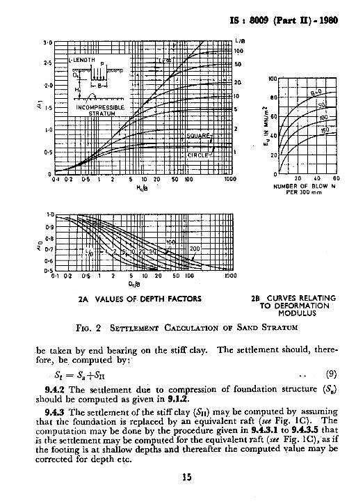
9.3.4 The settlement of the sand stratum (Sn) may be computed for the equivalent raft loading shown in Fig. ID by:
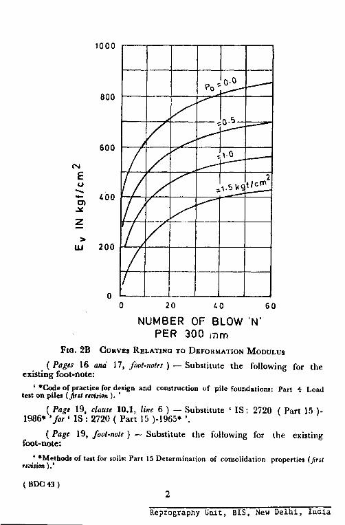
The constants ~1 and ‘pa may be read from Fig. 2A (where Hc=Hll). The deformation modulus Ev can be obtained or from standard penetration test. The curves relating deformation modulus to standard penetration resistance is shown in Fig. 2B.
NOTE 1 - In this case settlement is to be calculated for the loading at end and for the frictional loading separately, and the two added together to obtain the relevant value.
NOTE 2- In this type of situation, the settlement of the foundation may be many times the settlement at corresponding load in a single pile load test. Therefore, pile load test is not to be used for estimating settlement in this case.
Nom 3 -The possibility of development of negative skin friction should not be overlooked in this case (see 8.4).
9.4 End Bewing Piles Throagh Compressibk Strata into Stiff Clay
9.4.1 In this case, initially, unless the compressable strata is very soft the load would be mostly carried by skin friction but ultimately all the load would
14
IS: 8009 (Part II)-1980
3.0 LIB
190
2-5 50
?.O 20
10
$ I.5 5
1.0 2
0.5 1
0 0.1 0.2 0.5 1 2 5 10 20 50 (00 1000
Yb
0.6
0.5 0.1 0.2 0.6 I 2 5 10 20 50 100 1600
4/e
20 40 60
NUMBER OF BLOW N PER 300 mm
2A VALUES OF DEPTH-FACTORS 28 CURVES RELATING TO D;RO&WLAU.;ON
Fro. 2 SETTLEMENT CACCULATION OF SAND STRATUM
be taken by end bearing on the stiff clay. The settlement should, there- fore, be computed by:
s* = &+-&I . * (9) 9.42 The settlement due to compression of foundation structure (S,)
should be computed as given in 9.1.2.
9.4.3 The settlement of the stiff clay (&I) may be computed by assuming that the foundation is replaced by an equivalent raft (see Fig. 1C). The computation may be done by the procedure given in 9.4.3.1 to 9.4.3.5 that is the settlement may be computed for the equivalent raft (see Fig. lC), as if the footing is at shallow depths and thereafter the computed value may be corrected for depth etc.
15
IS : 8009 (Part II) - 1980
NOTE- Alternatively, the settlement of stiff clay may be computed as per 9.3.4. The modulus E, may be obtained from undrained test to work out the immediate settle- ment and from drained test to obtain the immediate plus consolidation settlement.
9.4.3.1 The total settlement should be computed from:
SIX -= Si+S, . . (10)
9.4.3.2 The immediate settlement may be computed by Equation 3 given in 9.1.4.1. The value of E in this case shall be determined from the stress-train curve obtained from triaxial consolidated undrained test with a consolidation pressure equal to effective pressure at the depth from which the sample was taken. The valrle of I may be determined from Fig. 11 of Part I of this Code (the value of Hn is same as Ht) for finite thickness of clay stratum or from Table 2 of Part I of this Code for semi-infinite clay stratum.
9.4.3.3 The consolidation settlement shall be calculated from:
s, = h Soed . . (111
Where
h = a factor related to the pore pressure parameter A and the ratio Hn/B and read from Fig.110 of Part I of this Code. In the ab- sence of data regarding A, it may be sufficient to take the value of X from Table 1 of Part I of this Code.
9.4.3.4 Soed m?y be calculated on the same lines as S; is calculated in 9.3.3 that is by Equation 6 or 7 as the case may be. (He = HI*).
9.4.3.5 The calculated settlement $1 may be corrected for depth of foundation by applying the depth factor correction read from Fig. 12 of Part I of this Code.
9.5 End Beaying Piles Embedded in Firm Stratum Underlain by Soft Clay Layer
9.5.1 If the bearing stratum is underlain by a soft clay layer, the settle- ment of the pile foundation is given by:
S, = Sa + Sc . . (12) S, may be computed, as if the soft clay layer does not exist, according to 9.3 or 9.4 as the case may be. S, may be calculated on the same lines as SI is calculated in 9.3.3 i.e. by Equation 6 or 7 as the case may be. S, may often be large compared to S, and therefore must not be overlooked.
Nare - In this case, Ho is equal to the thicknesxmf the soft clay layer.
9.6 Friction Piles in Cohessionless Soils
9.6.1 The settlement of a single pile in cohesionless soils can be reliably estimated by pile load test [see IS: 2911 (Part IV)-1979*].
*Code of practice for design and constrdc&@ of pile foundations: Part IV Load test on piles.
16
fc
5; is
01
9,
Sk
th
;
9,
E sh Ul
of cc hc rc
9.
w
tic -
on
IS : 8009 (Part II) - 1980
9.6.2 The settlement of a friction pile group in cohesionless soils is expec- ted to be less than the observed settlement of a test pile (driven alone- not a pile in the group) as the soil between the piles is compacted by dis- placement due to pile driving. It can reasonably be assumed that the settlement of a pile group in cohesionless soils will be equal to the settle- ment ofa well foundation having a depth and base equa.1 to the overall dimensions of the pile group estimated by Equation S and Fig. 2.
9.6.3 Alternatively, the settlement may be computed adopting one of the following formulae, suggested by Skempton and Mayerhoff respectively. Pile load test may be conducted after all the piles of the group have been driven [see IS : 2911 (Part IV)-1979*]. Then, the settlement of the group is given by:
s*= s, [“;I;;]z . . (13)
s(5 - r/3) or Sr = S
’ (1+1/r)2 (applicable only to a square group) . . (14)
9.7 Friction Piles in Cohesive Soils
9.7.1 The pile group may be replaced by on equivalent foundation as shown in Fig. IA or 1B (see 8.3.3 to 8.3.5). For this equivalent footing, the settlement may be computed by the same procedure as given in 9.4.3, 9.4.3.1 to 9.4.3.4 that is, the settlement may be computed for calculation of Srr, but depth correction is not applied in this case.
9.8 Pile Foundations in Erratic Deposits
9.8.1 In variable erratic soil deposits, if the variation occurs over distances greater than half the width of foundation, settlement analysis should be based on the worst and the best conditions. That is, worst properties should be assumed under the heavily loaded regions and the best properties under the lightly loadetl regions.
9.8.2 If the variation occurs over distances lesser than half the width of foundation, the settlement analysis should be based on worst and average condition. That is, the worst properties should be assumed under the heavily loaded region and the average properties under the lightly loaded regions.
9.9 Caissons atid Well Foundations
9.9.1 Two limiting cases can be identified in the case of Caissons and well foundations :
a) A smooth foundation with no adhesion, and b) A rough foundation with full adhesion.
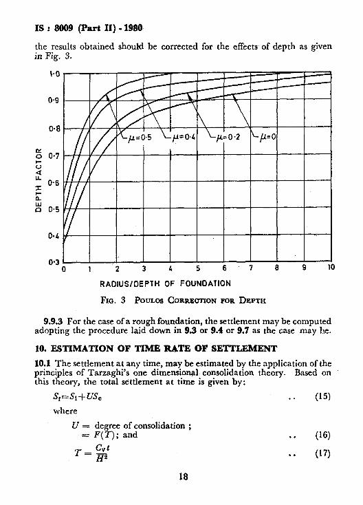
9.9.2 The case of smooth foundation can be treated as a shallow founda- tion and the relevant clauses in Part I of this Code may be seen; However,
*Code of practice for design and construction of pile foundations: Part IV Load test on piles.
17
IS : 8099 (Part II) - 1989
the results obtained should be corrected for the effects of depth as given in Fig. 3.
0 1 2 3 4 5 6.7 8 9 10
RADIUS/DEPTH OF FOUNDATION
FIG. 3 POULOS CORRECXION FOR DEPTH
9.9.3 For the case of a rough foundation, the settlement may be computed adopting the procedure laid down in 9.3 or 9.4 or 9.7 as the case may be.
10. ESTIMATION OF TIME RATE OF SETTLEMENT
10.1 The settlement at any time, may be estimated by the application of the principles of Tarzaghi’s one dimensional consolidation theory. Based on this theory, the total settlement at time is given by:
s*=s,+vs, . . (151
where
U = degree of consolidation ; = F(T); and . . (1’5)
18
IS : 8009 (PartII)-1980
The relationship between ?-and Uin Equation (16), depends on pressure distribution and nature of drainage, This relationship is shown in Fig. 13 of Part I of this Code. When considering the drainage of clay layer, concrete of foundation may be assumed as permeable. The coefficient of consolida- tion shall be evaluated from the one dimensional consolidation tests using suitable fitting methods [see IS : 2720 (Part XV)-1965*].
10.2 In the case of evaluation of time rate of settlement of structures cons- tructed with certain construction time, the procedure illustrated in Appendix D of Part I of this Code m.ay be followed.
Methods of test for soils: Part XV Determination of consolidation prop&~.
19
IS : 8009 (Part II) - 1980
(Continuedfrom Page 2)
Members
DEPUTY DIRECTOR (SM II), RDSO
Representing
RESEARCH Ministry of Railways
DEPUTY DIRBCTOR STANDARDS (B & S CB II), RDSO (,4lternale)
SHRI M. IYENCAR Engineers India Limited, New Delhi SHRI J. K. BAGCHI (Alternate)
SHRI B. K. PANTHAKY Hindustan Construction Co Limited, Bombay SHRI P. V. NAIK (Alternate)
SHRI M. R. PUNJA Cemindia Company Limited, Bombay SHRI S. MUKHERJEE (Alternate)
SHRI D. SHARMA Central Building Research Institute (C-SIR), Roorkee
SUPERINTENDING ENGINEER (DESIGNS) Central Public Works Department, New Delhi EXECUTIVE ENGINEER (DESIGNS) V (Alternate)
Adhoc Panel for Preparation of Code of Practice for Calculation of Settlement of Foundations,
BDC 43:5:1
Membn
DR S. MUTHIJK~MARAN Department of Education (Ministry of Education & Culture)
20
BUREAU OF INDIAN STANDARDS
Heedquarters :
Manak Bhavan, 9 Bahadur Shah Zafar Marg. NEW DELHI 110002
Telephones : 331 01 31 Telegrams : Manaksanstha
331 13 75 (Common to all Offices) Regional Offices :
Central : Manak Bhavan. 9. Bahadur Shah Zafar Marg. NEW DELHI 110002
l Eastern : l/14 C.I.T. Scheme VII M. V.I.P. Road, Maniktola. CALCUTTA 700054
Northern : SC0 445-446, Sector 35-C, CHANDIGARH 160036 Southern
t Western : C.I.T. Campus, IV Cross Road, MADRAS 600113 : Manakalava, E9 MIDC. Marol. Andheri (East),
t
BOMBAY’400093 Branch Offices :
‘Pushpak’, Nurmohamed Shaikh Marg, Khanpur, AHMADABAD 380001 Peenya Industrial Area, 1st Stage, Bangalore-Tumkur Road,
BANGALORE 560058 Gangotri Complex, 5th Floor, Bhadbhada Road, T.T. Nagar,
BHOPAL 462003 Plot No. 82/83, Lewis Road, BHUBANESHWAR 751002 Kalai Kathir Building, 6/48-A Avanasi Road, COIMBATORE 641037 Quality Marking Centre, N.H. IV, N.I.T., FARIDABAD 121001 Savitri Complex, 116 G. T. Road, GHAZIABAD 201001 5315 Ward No. 29, R.G. Barua Road. 5th By-lane,
GUWAHATI 781003 5-8-56C L. N. Gupta Marg. ( Nampally Station Road )
HYDERABAD 500001 R14 Yudhister Marg. C Scheme, JAIPUR 302005
1171418 8 Sarvodaya Nagar, KANPUR 208005 , Plot No. A-9, House No. 561/63. Sindhu Nagar, Kanpur Roao.
LUCKNOW 226005 Patliputra Industrial Estate, PATNA 800013
District Industries Centre Complex. Bagh-e-Ali Maidan, SRINAGAR 19Opll
T. C. No. 14/1421, University P. O., Palayam. THIRUVANANTHAPURAM 695034
/nspection Offices (With Sale Point) : Pushpanjali. First Floor, 205-A West High Court Road.
Shankar Naaar Sauare. NAGPUR 440010 Institution of -Engineers .(lndia) Building, 1332 Shivaji Nagar.
PUNE 411005 --_
*Sales Office Calcutta is at 5 Chowringhee Approach, P. 0. Princep Street, CALCUTTA
t Sales Office, is at Novelty Chambers, Grant Road, BOMBAY
~A~~~L~~ce is at Unity Building, Narasimharaja Square,
Telephone
i 331 01 31
333: is3 :26
21843 41 29 16
6 32 92 95
2 63 48 39 49 55
55 40 21
5 36 27 2 67 05
8-71 19 96 3 31 77
231083
6 34 71 21 68 76
5 5507
6 23 05
6 21 04
52 61 71
5 24 36
27 68 00
89 65 28
22 39 71
Reprography Unit, BIS, New Delhi, India
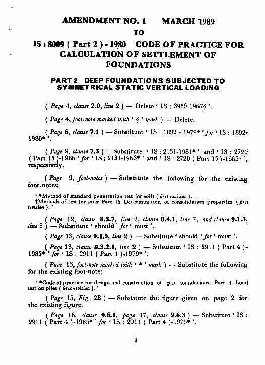
AMENDMENT NO. 1 MARCH 1989 TO
IS : 8009 ( Part 2 ) - l?SO CODE OF PRACTICE FOR CALCULATION OF SETTLEMENT OF
FOUNDATIONS
PART 2 DEEP FOUNDATIONS SUBJECTED TO SYMMETRICAL STATIC VERTICAL LOADING
( Page 4. clause 2.0, line 2 ) - Delete ‘ IS : 3955-1967s ‘.
( Page 4, foot-note matked with ‘ 5 ’ mark ) - Delete.
( Page 8, clause 7.1 ) - Substitute c IS : 1892 - 1979* ‘for ( IS : 1892- 1980+ ‘.
( Page 9, clause 7.3 )-Substitute ‘ IS : 2131-1981* ’ and ‘ IS : 2720 ( Part 15 )-1986 ‘f OY ‘ IS : 2131-1963; ’ and ‘ IS : 2720 ( Part 15 )-1965t ‘, rapectively.
( Page 9, foot-notes ) - Substitute the following for the existing foot-notes:
‘ l Method of standard penetration test for soiln (jlrzt reuision ). tMethods of test for soils: Part 15 Determination of consolidation properties (first
rrti ). ’
( Page 12, clause 8.3.7, line 2, clause 8.4.1, line 7, and clause 9.1.3, line 5 ) - Substitute ‘ should ‘for ‘ must ‘.
( Page 13, clause 9.1.5, line 2 ) - Substitute ‘ should ‘for ‘ must ‘.
( Page 13, clause 8.3.2.1, line 2 ) - Substitute ‘ IS : 2911 ( Part 4 )- 1985* ‘for ‘ IS : 2911 ( Part 4 ).1979* ‘.
( Page 13, foot-note marked with 6 * ’ mark ) - Substitute the following for the existing foot-note:
‘ *Code of practice for design and construction of pile foundations: Part 4 Load test on piles (jr st rtoirion ) . ’
( Page 15, Fig. 2B ) - Substitute the figure given on page 2 for the existing figure.
( Page 16, clause 9.6.1, Page 17, clause 9.6.3 ) - Substitute ‘ IS : 2911 ( Part 4 )-1985* ‘for ’ IS : 2911 ( Part 4 )-1979* ‘.
1
800
0 0 20 LO 60
NUMBER OF BLOW ‘N’ PER 300 ram
FIG. 2B CURVES RELATING TO DEFOHMATION MODULUS
( Pages 16 and 17, foot-notes ) - existing foot-note:
Substitute the following for the
‘ *Code of practice for design and construction of pile foundations: Part 4 Load test on piles ( jfirsl rrtision ). ’
1986* ( Pags 19, clause 10.1, fine 6 ) - Substitute ‘ IS: 2720 ( Part 15 )- ‘for ‘ IS : 2720 ( Part 15 )-1965* ‘.
( Page 19, foot-note ) - Substitute the following for the existing
foot-note:
‘ *Methods of test for soils: Part 15 Determination of consolidation properties (prst rrvision ).’
(BDC43)
2
Reprography Unit, BIS, New Delhi, India
3. SYMBOLS
3.1 For the pu text the followi each :
A = A1
B =w c, ==ct c, =A Df = DI
D, = Ll
EV =R!
EP = h
>c
= II = T!
HI = Tl
HII = T:
mv = CI = P’
; =l
Ptj =f
P I rz
PO =: =
;; =I
SL =I &I = ’ s, =
SC 7 s* = si = S oed =