is 5822 (1994): code of practice for laying of … preliminary work required to be done before pipe...
TRANSCRIPT

Disclosure to Promote the Right To Information
Whereas the Parliament of India has set out to provide a practical regime of right to information for citizens to secure access to information under the control of public authorities, in order to promote transparency and accountability in the working of every public authority, and whereas the attached publication of the Bureau of Indian Standards is of particular interest to the public, particularly disadvantaged communities and those engaged in the pursuit of education and knowledge, the attached public safety standard is made available to promote the timely dissemination of this information in an accurate manner to the public.
इंटरनेट मानक
“!ान $ एक न' भारत का +नम-ण”Satyanarayan Gangaram Pitroda
“Invent a New India Using Knowledge”
“प0रा1 को छोड न' 5 तरफ”Jawaharlal Nehru
“Step Out From the Old to the New”
“जान1 का अ+धकार, जी1 का अ+धकार”Mazdoor Kisan Shakti Sangathan
“The Right to Information, The Right to Live”
“!ान एक ऐसा खजाना > जो कभी च0राया नहB जा सकता है”Bhartṛhari—Nītiśatakam
“Knowledge is such a treasure which cannot be stolen”
“Invent a New India Using Knowledge”
है”ह”ह
IS 5822 (1994): Code of Practice for Laying of ElectricallyWelded Steel Pipes for Water Supply [CED 24: Public HealthEngineering.]

IS 5822 : 1994
Indian Standard
CODEOFPRACTICEFORLAYINGOF ELECTRICALLY WELDED STEELPIPESFOR
WATERSUPPLY
f Second Revision )
UDC 621-643-2-073 [669-14-4621 : 628.1 : 006.76
Q BIS 1994
BUREAU OF INDIAN STANDARDS MANAK BHAVAN. 9 BAHADUR SHAH ZAFAR MARG
NEW DELHI 110002
July 1994 Price Group 7
Water Supply and Sanitation Sectional Committee, CED 24
FOREWORD
This Indian Standard ( Second Revision ) was adopted by the Bureau of Indian Standards, after the draft finalized by the Water Supply and Sanitation Sectional Committee had been approved by the Civil Engineering Division Council.
The selection of a pipeline for any particular application depends on the service and environmental conditions to be satisfied. With the development of new materials and jointing methods, changes in the application and in design can be expected, but it is the responsibility of every authority to ensure that the type of the pipeline selected is suitable and safe for the duty envisaged. The earlier disadvantages of steel pipelines ( liability to deteriorate by corrosion ) have been largely overcome in recent years due to development of protective coatings, and steel pipelines may now be safely used for carrying certain fluids. This standard was first published in 1970 and subsequently revised in 1986. The present revision incorporates the following major changes:
a) Inclusion of 168.3 mm outside diameter pipe,
b) Criteria for calculating the nominal thickness has been modified, and
c) Criteria for selecting protective coatings has been modified,
In the formulation of this code due weightage has been given to international co-ordination among standards and practices prevailing in different countries in addition to relating it to the practices in the field in this country. This has been met by deriving assistance from the following standards:
BS CP 8010-1981 ‘Code of practice for pipelines’ British Standards Institution.
BS CP 2010 ( Part 2 ) ‘Pipelines: Part 2 Design and construction of steel pipelines in land’ British Standards Institution.
The Committee responsible for the preparation of this standard is given in Annex C.
IS 5822 : 1994
Indian Standard
CODE OF PRACTICE FOR LAYING OF ELECTRICALLY WELDED STEEL PIPES FOR
WATER SUPPLY
( Second Revision )
1.1 This code covers the melhods of laying electrically welded mild steel pipes ofoutsidc diameters 16S.3 nun IO 2 032 nun (as covered iu IS 3589 : 199i), laid either above ground or underground for water supply.
1.2 For the purpose of this code, elcclrically welded stcrl pip’s shall cnnfom to IS 3589’: 1991; mild sleel plates to IS 2062 : 1992 and welding rlectrodes to IS 814 : 1991.
2.1 The Indian Standards listed in Amex A are nercs- sary i\djL\lKtS lo this standard.
3 CI,EARIN(; THE SIl’E
3.1 Preliminary work required to be done before pipe laying is started, includes pegging out, clearing and disposal of all shrub, grass, Iage and sn~ll hushes, trees, hedges, fences, gates, portions of old masonry and debris from the route.
3.2 Whcrc trees have been Mlcd, the resulting timber shall be stacked properly aud disposed off, as directed by the authority. Tree roots within a distance of about half nlctre from the side of the pipeliuc shall be rcnloved or killed.
3.3 All other scrviceablc materials, such as wood work, bricks and nlasoury, recovered during the operation of clearing the site shall be separately stacked aud dis- pscd OK, as direcled by Ihe authority. .
NOTE - For the purpxe of this code, authority may be an individual, an oflicial, a board, a department or an agency established and authorized by the llnion or State (%~vcrumenl or any slatutory body created by law who tdertakes to administer ilnd enforce the provisions of lhis cock as adopted or amended.
4 IWHMA’ITON
4.1 (;rwt-al
Bct’orr pipeline is laid, proper fornration shall be prcparcd. For buried pipeline, suitable trenches should be exraVi~ted, pipeline above ground may be laid in autting or on embanknients or be supported~by pillars as the cast inay be.
4.2 Excavation and Preparation of Trenches for Laying 1hdrrground Pipeline
The trench shall be so dug that the pipe nlay be laid to the rcquircd alignment and at required depth. When the pipeline is under a roildWay, a niininiuni cover of 1.0 iii
is recoiiiiiieiided, but it may be niodified to suit local couditions by taking necessary precautions. The trench shall bc shored, wherever necessary, and kept dry so that the workman may work therein safely, and effi- ciently. The discharge of Ihe trench dewatering pumps shall he conveyed &her to drainage charnels or to natural drains, and shall not be allowed to be spread in the vicinity of Ihe worksite.
4.2.1 Trenching
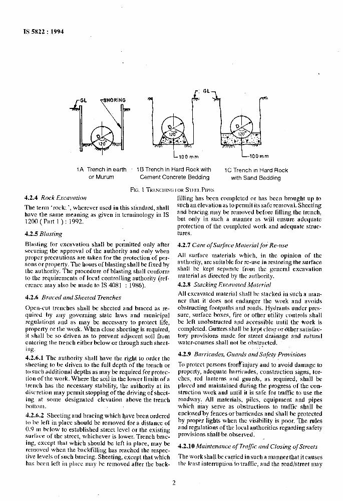
Trenchiug includes all excavation which is carried out by hand or by machine. The width of the trench shall be kept toa mii~luumcoitcisteiltwith theworkingspace required. At the bottom belween the faces, it shall be such as to provide not less than 200 mm clearance on tither side of the pipe. Each case should, however, he considered on its merits, having regard to rhe safety of the Irench, the method of laying and jointing the pipe and lhe need to avoid damage to pipe.coating. The bottom of the trench shall be properly trinmed to permit even bedding of the pipeline. For pipes larger than 1 200 mm diameter in earth and munm the curva- ture of the boottom of the trench should match the curvature of the pipe as far as possible, subtending an angle of about 120* at the centrc of the pipe, as shown in Fig. 1 A. Where rock or boulders are encountered, the trench shall be trinmed to a depth of at least 100 nun below the level at which the botion~ of the barrel of the pipe is to be laid and filled to a like depth with lean ccmentcoucrc~eorwi~h non-compressible material like sand of adequate depth to give the curved seating, as shown in Fig. 1B and Fig. 1C.
4.2.2 Pits for Joints
When welding is to be carried out with the pipe in the trench, additional excavation of not more than 600 nun in depth and 900 nun in length should be provided all round the pipe at the position nf the jointsfor facilities of welding.
4.2.3 Specicll Forrndrltions in Poor Sail
Where the bottom of the trench at subgrade is found to consist of niaterial which is unstable to such a degree that, .in the opinion of the authority, it cannot be removed and replaced with an approved material thoroughly conipacted in place to support the pipe properly, a suitable foundation for the pipe, consisting of piling, timbers or other materials, in accordance with plans~prepared by the authority, shall 1~ constructed.
IS 5822 : 1994
RL \
Igru 0 0 I20" ._ ._ ,
. . .a,' > ..a .*,'. Q VT_.
120° ;.a+
;+.,. t(*. . . .
tf..;: :L
\ J \ \
100 mm 100 mm
1 A Trench in earth 1 B Trench in Hard Rock with 1 C Trench in Hard Rock or Murum Cement Concrete Bedding with Sand Bedding
FE. 1 TKENUUNC; FOR SEEL PIPFS 4.2.4 Rock Excwation
The term ‘rock:‘, wherever used in this standard, shall have the same meaning as given in teminoiogy in IS 1200 ( Part 1 ) : 1992.
4.2.5 BIllsting
Blasting for excavation shall be per~uitted only after securing the approval of the authority and only when proper precautions are taken for the protection of per- sons or property. The hours of blasting shall be fixed by the authority. The procedure of blasting shall conform to the requirements of local controlling authority (rrl- crcucc may also be made to IS 4081 : 1986).
4.2.6 Brcrccd and Slrwted Trenclres
Open-cut trenches shall bc sheeted and braced as re- quircd by any goveruing state laws and nnmicipai reguiil tiolls and as may be necessary to protect life, propcrty or the work. When close sheeting is required, it shall bc so driven as to prevent adjacent soil from entering the trench either below or through such sheet- ing.
4.2.6.1 The authority shall have the right to order the shccting to be driven to the full depth of the trench or to such additional depths as may bc required for protec- tion of the work. Where the soil in the lower limit5 of a trench has the necessary stability, the au’thority at its discrctioa may permit stopping of the driving of sheet- ing at some designaled elevation above the trench bottolll.
4.2.6.2 Sheeting and bracing which have been ordered to bc left in place should be removed for a distance of 0.9 m bciow to established street level or the existing surface of the street, whichever is lower. Trench brac- ing, except that which should be left in piacc, may be rcniovcd when the backfilling has reached the respec- tivc icvels of such bracing. Sheeting, except that which has bccu icft in piacc III;I~ IK: removed after the ixlck-
filling has been completed or has been brnught up to such an elevation as to pemil its safe removal. Sheeting and bracing may be rcnmved before filling the trench, but only in such a manner as will ensure adequate protection of the conipieted work and adequate struc- tures.
4.2.7 Cm-e of Surfirce Mrrterinl fo; Re-use
Ail surface materials which, in the opinion of the authority, are suitable for re-use in restoring the surface shall be kept separate front the general excavation material as directed by thr authority.
4.2.X Stocking Excavated Mrrtericll
Ail excavated material shall bc stacked in such a man- ner that it does not endanger the work and avoids obstructing footpaths and roads. Hydrants under prcs- sure, surface boxes, fire or other utility controls shall be left unobstructed and accessible uutii the work is completed. Gutters shall be kept cIcar orfiher satisfac- tory provisions made for street d&nage and natural water-courses shall not be obstructed.
4.2.9 Brrrrictldes, Guards trnd Srlfety Provisions
To protect persons fror#injury and to avoid damage to property, adequate barricades, construction signs, tor- ches, red ianterm and guards, as required, shall be placed and maintained during the progress of the con- struction work and until it is safe for traCfic to use the roadway. All materials, piles, equipment and pipes which niay serve as obstructions to traffic shall be enclose&y fences or barricades and shall be protected by proper lights when the visibility is poor. The rules and regulations pf the local authorities regarding safety provisions shall be observed.
4.2.10 Mtrintenance of Traffic and Closing of Streets
Theworkshaii becarriedinsucha mannerthatkcauses thr Icast interruption to~traffic, and the road/street may
2
IS 5822 : 1994
4.3 Preparation of Formation for Pipeline Above Ground
Formation should be prepared by cutting high grounds and filling in low areas. Care shall be taken while fixing the alignment and gradient of the pipeline, to balance the cutting and filling quantities, as far as possible, with minimum of lead. Care should also be taken to ensure that the pipe rests fully either on cutting or on bank.
4.3.1 Cutting High Grounds
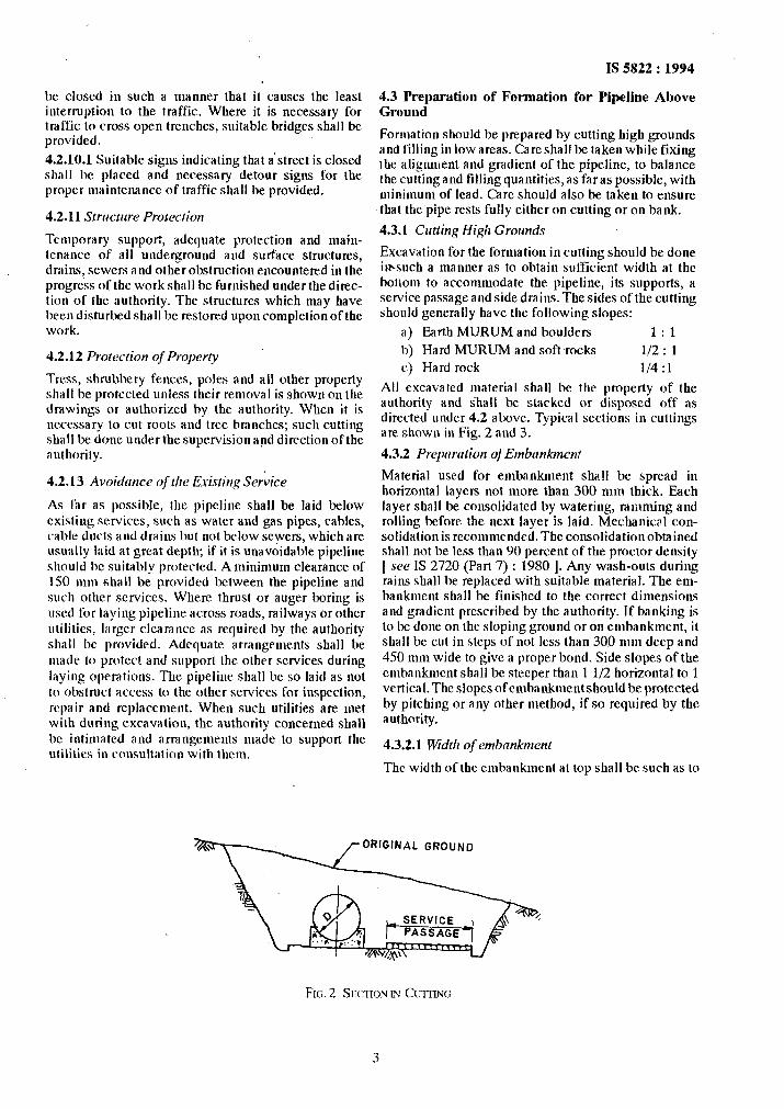
Excavation for the formation in cutting should be done il+such a manner as to obtain sufficient width at the botiom to accommodate the pipeline, its supports, a service passage and side drains. The sides of the cutting should generally have the following slopes:
a) Earth MURUM and boulders 1:l b) Hard MURUM and soft frocks l/2 : 1 c) Hard rock l/4 :l
All excavated material shall be the property of the authority and shall be stacked or disposed off as directed under 4.2 above. Typical sections in cuttings are shown in Fig. 2 and 3.
4.3.2 Preparation of Embankmen!
Material used for embankment shall be spread in horizontal layers not more than 300 mm thick. Each layer shall be consolidated by watering, ramming and rolling before the next layer is laid. Mechanical con- solidation is recommended. The consolidation obtained shall not be less than 90 percent of the proctor density [ see IS 2720 (Part 7) : 1980 1. Any wash-outs during rains shall be replaced with suitable material. The em- bankment shall be finished to the correct dimensions and gradient prescribed by the authority. If banking is to be done on the sloping ground or on embankment, it shall be cut in steps of not less than 300 mm deep and 450 mm wide to give a proper bond. Side slopes of the embankment shall be steeper than 1 l/2 horizontal to 1 vertical. The slopes of embankment should be protected by-pitching or any other method, if so required by the authority.
4.3.2.1 Width of embankment
The width of the embankment at top shall be such as to
be closed in such a manner that it causes the least interruption to the traffic. Where it is necessary for traffic to cross open trenches, suitable bridges shall be provided.
4.2.10.1 Suitable signs indicating that a’street is closed shall be placed and necessary detour signs for the proper maintenance of traffic shall be provided,
4.2.11 Structure Protection
Temporary support, adequate protection and main- tenance of all underground and surface structures, drains, sewers and other obstruction encountered in the progress of the work shall be furnished under the direc- tion of the authority. The structures which may have been disturbed shall be restored upon completion of the work.
4.2.12 Protection of Property
Tress, shrubbery fences, poles and all other property shall be protected unless iheir removal is shown on the drawings or authorized by the authority. When it is necessary to cut roots and tree branches; such cutting shall be done under the supervision and direction of the authority.
4.2.13 Avoidmce of the Existing Service
As f:ir as possible, the pipeline shall be laid below existing services, such as water and gas pipes, cables, cable ducts and drains but not below sewers, which are usually laid at great depth; if it is unavoidable pipeline should be suitably protected. A minimum clearance of 1.50 mm shall be provided between the pipeline and such other services. Where thrust or auger boring is used for laying pipeline across roads, railways or other utilities, larger clearance as required by the authority shall be provided. Adequate arrangements shall be made to protect and support the other services during laying operations. The pipeline shall be so laid as not to obstruct access to the other services for inspection, repair and replacement. When such utilities are met with during excavation, the authority concerned shall bc intimated and arrangements made to support the utilities in consultation with them.
ORIGINAL GROUND
FIG. 2 SE(-IlON m Cum~ci
3
IS 5822 : 1994
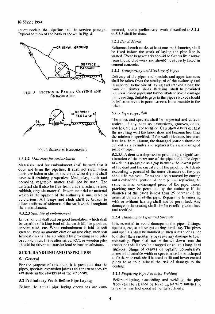
accommodate the pipeline and the service passage. Typical section of the bank is shown in Fig. 4.
ORIGINAL GRDUND
FIG. 3 SECTION IN PARTLY CUTTING AND EMBANKMENT
FK. 4 SKEIN IN EMB~N?
4.3.2.2 Mrltericlls jbr emhnkment ’
Materials used for embankment shall be such that it does uot ham the pipeline. It shall not swell when moisture laden or shrink and crack tihen dry and shall have self-draining properties. Mud, clay, slush and decaying vegetable matter shall not be used. The material shall also be free from cinders, ashes, refuse, rubbish, organic material, frozen material or material which in the opinion of the authority is unsuitable or deleterious. All lumps and clods shall be broken to allow uniform subsidence of the earth work throughout the embankment.
4.3.2.3 Strrbility of embankment
Eulbankment shall rest on good foundation which shall be capable of taking load of the earth fill, the pipeline, service road, etc. When embankment is laid on soft ground, such as marshy clay or marine clay, such soft foundation shall be stabilized by providing sand piles or rubble piles.Tn the alternative, RCC or wooden piles should be driven to transfer load to harder substrata.
5 PIPE HANDLING AND INSPECTION
5.1 General
For the purpose of this code, it is presumed that the pipes, specials, expansion joints and appurtenances are available in the stockyard of the authority.
4
5.2 I’relitninary Work Before Pipe.Laying
Before the actual pipe laying opclations are corn--
menced, some preliminary work described in 52.1 to 52.5 shall be done.
5.2.1 Bench Marks
Refercure bench marks, at least one per kilotnetre, shall be fixed before the work of laying the pipe line is started. These bench marks should be fixed a little away from the field of work and should be securely fixed in cement concrete.
5.2.2 Transporting md Stmking of Pipes
Delivery of the pipes and specials and appurtenances shall be taken from the stockyard of the authority and Iransportcd to the site of laying and stacked along the rotllr on timber skids. Padding shall be provided IK~I\L.c~~ coated pipes and timberskids to avoid damage 10 IIIC coating. Suitable gaps in the pipes stacked should be left at intervals to pcnnit access from one side to the other.
5.2.3 Pip Inspection
7l1e pipes and specials shall be inspected and defects noticed, if any, such as protrusions, grooves, dents, notches, etc, shall be rectified. Care should bc taken that the resulting wall thickness does not become less than the uiinimum specified. If the wall thickness becomes less than the u~ininum, the damaged portion should be cut out as a cylinder and replaced by an undamaged piece of pipe.
5.2.3.1 A dent is a depression producing a significant alteration of the curvature of the pipe shell. The depth of a dent is measured as a gap l~etwec~~ the lowest point of the dent and~the curvature of the pipeline. All dents exceeding 2 percent of the outer diameter of the pipe should be removed. Dents shall bc removed by cutting out a c.ylindrical portion of the pipe aud replacing the same with an undamaged piece of the pipe. Insert patching may be permitted by the authority if the diameter of the patch is less than 25 percent of the nominal diameter of the pipe. Repairs by hammering with or without heating shall not be permitted. Any damage to the coating shall also bc carefully examined and rectified.
5.2.4 Handling of Pipes trnd S@ecirrls
It is essential to avoid daniagc to the pipes, fittings, specials, etc, at all stages during handling. The pipes and specials shall be handled in such a nlanuer as not to distort their circularity 01 cause any damage to their outcoating. Pipes shall not be thrown down from the trucks nor shall they be dragged or rolled along hard surfaces. Slings of canvas on equally non-abrasive material of suitable width or special attachnient shaped to fit the pipe ends shall be used to lift and lower~coated pipes so as to eliminate the risk of damage to the coating.
5.2.5 Prepring Pipe Fnces for Welding
Before aligning, assembling and welding, the pipe faces shall be cleaned by scraping by wire brushes or any other method specified by the authority.
6 WEIAI)ING
6.1 General
The welding of pipes in the field should comply with IS 816 : 1969. Electrodes used for welding should comply with IS 814 : 1991.
6.2 lkstiug of Welded Joints
The welded joints shall be tested in accordance with procedure laid down in IS 3600 ( Part 1 ) : 1985. One test spcrimen taken from at least one field joint~out of any 10 shall bc subjected to test.
6.2.1 If the resuhs of the tensile test do not conform to the rccluircments specified, retests of two additional specinlcn from the same section shall be made, earh of which shall conform to the required specifications. In CiISC of failure of one or two, extensive gouging (scoop- ing out) and repairing shatl be carried out as directed by the authority.
6.2.2 If internal pressures exceed 1.5 N/mm2, special altcntion should bc given to the assembly of the pipe and first ruu of weld. Non-destructive testing of the completed weld may be carried out on pipelines by radiographic (see IS 4853 : 1982) or ultrasonic method ( .s~<J 1s 4260 : 19X6 ) as agreed upon between the user and the manufacturer.
6.3 Weldiug of Closure Gaps
Final welding of closure gaps should be carried out within ;I temperature range of average air temperature I S “C. For buried pipelines final welding may best be done after intermediate pipes have been backfilled.
7 HANK FLANGES
7.1 Blank flanges shall be used at all ends left unat- tended at the. temporary closure of work..Blank flanges nlay also bc necessary for commissioning a section of the pipeline or for testing the pipeline laid. For tem- pnrary closures, non-pressure blank flanges consisting of mild steel plates tack-welded at the pipe ends may be used. For pipes subjected to pressures, the blank flanges should be suitably designed. To prevent the floating of pipes, care should be taken to see that empty pipes with ends blank flanged should not be left in uncovered trenches, where water is iikely to accumu- hk.
8 1’11% LAYING
8.1 Iayiug of Pipes IJnderground
Ir.l.1 Gerrerrrl
The procedure for trenching as described in 4.2 and 4.2.1 shall be carefully followed. Before the pipe is lowered, the trench shall be carefully examined to determine that an even bedding is provided for the pipelineand that the pipe may belowered intoitwithout damaging the coating.
8.1.2 Lowering ondAssentbling of Pipes and Speciuls
The procedure for lowering varies with the method adopted for coating the pipeline. Where the coating is
IS 5822 : 1994
to be done in the trench, the pipe may be lowered in the trench on supports sufficiently high so as to facilitate out-coating. The pipe should be lowered progressively with the help of shear legs or cranes using wide belts or slings. In case of coated pipes, extra care shall be taken to preserve the coating while lowering. Slings may be removed progressively without the necessity ofdigging under the pipe. Where the trench is sheeted, the pipes shall be lowered into the trench by removing at a time, one or two struts only, care being taken to see that no part of the shoring is disturbed or damaged. If neces- sary, additional struts may be fixed during lowering. After the pipe is lowered, it shall be laid in correct line and level by use of levelling instruments, sight rails, theodolites, etc. Care shall be taken to see that -the longitudinal joints of the consecutive pipes are stag- gered by at least 30” and should be kept in upper third of the pipeline, if there are two longitudinal joints they should be on the sides. While assembling, the pipe faces shall be brought close enough to leave a unifoml gap not exceeding 3 mm. The spiders from imide and tightening rings from outside or other suitable equip- ment should be used to keep the two faces in shape and position till at least one run of welding is carried out.
Q2.1 The pipe faces shall first be tack-welded alter- nately at one or more (liametrically opposite pairs of points. After completing tack-welding, full welding shall be carried out in suitable runs following a se- quence of welding portions of segments diametrically opposite.
8.2 &&filling
Backfilling should closely follow the welding of joints of the pipe so that the protective coating should not be sub+eo_llently damaged. Material hannful to the pipe- line shall not be used for backfilling. Refilling shall be done in layers not exceeding 300 mm. Each layer shall be consolidated-by watering and ramming, care being taken to prevent damage to the pipeline. The filling on the niro sides of the pipeline should be carried out simultaneously.
8.2.1 The spiders provided during assembly and weld- ing shall be retained until the trench is refilled and consolidated. Where timbers are placed under the pipeline to aid alignment, these shall be removed before backfilling. For further precautions and use of material in backfilling, reference should be made to IS 3114 : 1994.
8.3 Laying of Pipes Above Ground
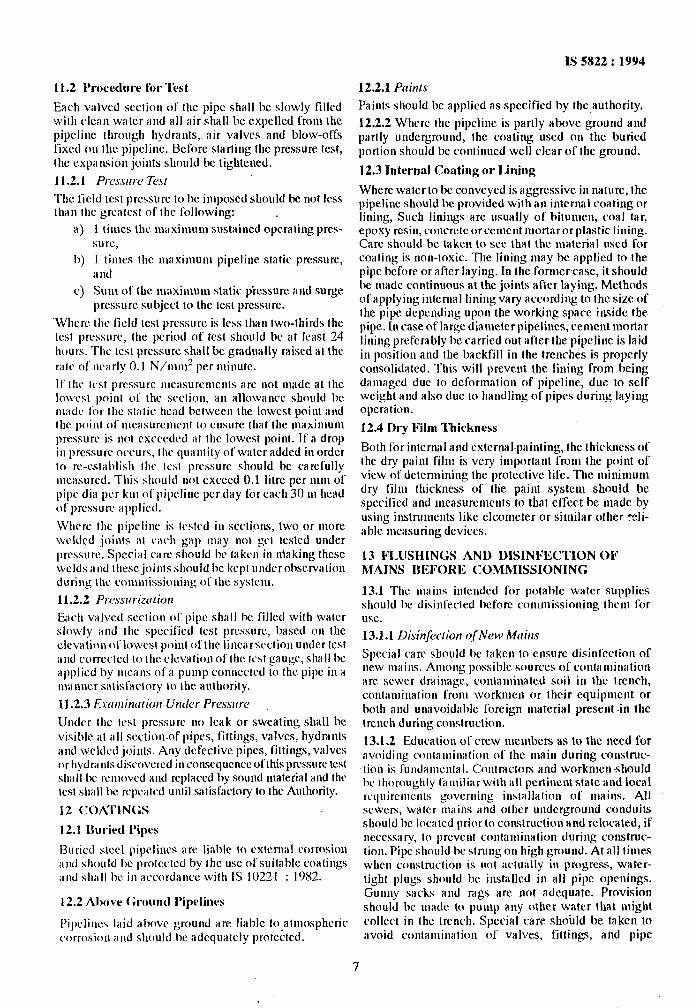
8.3.1 General The procedure for handling the pipes as described in 5 and for lowering and assembling the pipes underground as described in 8.1.2 should be followed for lifting and laying the pipes on supports or on ground. The pipeline may be allowed to rest on ground, if the soil is non-aggressive. The ground should, however, be dressed to match the curvature of the pipe shell for an arch length subtending an angle of 120° at the centre of pipes. Alternatively, the pipeline should be laid either on saddle or roller and rocker supports as specified by
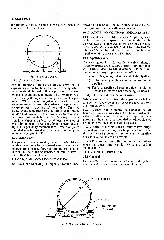
IS 5822 : 1994
the authority. Figures 5 and 6 show supp&ts gcucrally ;idoplcd 011 slrcl pipcliws.
For all pipelines laid above ground, provision for expansion and contraction on accouut of temperature variationshould be made either by providing expansion joints at predetermined intervals or by providing loops where leakage through expansion joitlts cannot bc per- mitted. Where expansion joints are provided, it is necessary to create restraining points on the pipeline to ensure proper functioning of these joints. The pipe laying work should preferably start from the restrained points on either side working towards centre where the cxpamiou joint should be fitted last. Spacing ofexpan- sion joint depends on local conditions. Provision of expamion joint at intervals of 300 man exposed steel pipeline is gcncrally recommended. Expansion joints should always be provided between two fixed supports or anchorages (see 8.3.3).
8.3.3 Anchortrp
The pipe shall IX anchored by concrete anchor blocks or other means to resist unbalanced water pressures and tenlpemturc stresses. Provision should be made to anchor the main during construction and in service where floatation could occur.
Y ROAD, MH, AND RIVER CHOSSING
9.1 The mode of laying the pipeline crossing. road,
G
railway or a river shall be detemincd so as to satisfy the rcquiremnts of the authority concerned.
10 BMNCH CONNECTIONS, SPECIALS, ETC
10.1 Complicated specials, such as ‘Y’ pieces, coni- positc bends and tapers, shall be fabricated in workshop. Small branches, single piece bends, etc, may IX fabricated at site, care being taken to ensure that the fabricated fittings have at least the sang strength as the pipeline to which these are to be joined.
10.2 Appurtenances
The spacing of the isolating sluice valves along a pipeline depends upon the type of terrain through which the pipclinc passes and the operational flexibility rc- quircd. Valves may be positioned as follows:
a) At the beginning and at the end of the pipeline;
b) To facilitate hydraulic testing of sections or the pipeline;
c) For long pipelines, isnlating valves should be provided at intervals not exceeding 6 km; and
d) On either side of a major crossing.
Valves may bc located cithcr above ground or below ground, but should bc easily accessible (see IS 780 : 1984 and IS 2906 : 1984 ).
10.2.1 Control valves should be provided on all branches. Similarly, air valves at all humps and scour valves at all dips are necessary. For inspection pur- poses, man-holes may be provided on either side of isolating valve and at other suitable places.
10.2.2 Protective devices, such as relief valves, surge or break pressure stations, may be provided to ensure that the internal pressure at any point in the pipeline dots not exceed the design pressure.
102.3 Pressure indicating the flow recording instru- ments and burst alarms should also be provided at suitable places.
11 TESTING OF PIPELINE
11.1 GearI-al
Bclijrc putting it into ronmission. the wcltlcd pipeline shall 1)~ trstrd both Ihr its strength ,Ind Ic;~kagc.
GIRDER
STOOL
,ROLLER OR ROCKER
11.2 I’rocediwe for’l‘est
Each valved section of the pipe shall be slowly filled with clean water ilnd all air shall IX expelled from the pipclit1e through hydrants,. air valves and blow-offs fixed ou the pipeline. Before starting the pressure test, the expansion joints should 1~ tightened.
11.2.1 Prcwtw Test
The field test pressure IO be imposed should be not Icss than the grcatcst of the fOlIowing: .
1 times lhc u~i~xiniuiii sustained operating prcs- sun:,
1 times the maximum pipeline static pressure, a lld
Sun1 of the niaxinlum static pressure and surge pmsurc subject to the test prcssurc.
~Whcrc the licld test pressure is less than two-thirds the I~SI pressure, the period of test should be at least 24 hours. The test pressure shall be gradually raised at the rate 01’ ne;lrly 0.1 N/IUIU’ per minute.
lf the test prcssurc mcasurenm~ts arc not made at the lowcs~ point of the scctiou, an allowance should be made for the static head l~ctwccn the lowest point aud the point of nlcasurcmcnt to ensure that the IIMX~IMII~I pressure is no1 cxcccdcd at tlic lowrst poiiil. If a drop
in prcssurc occurs, the quanlity of water added in order to re-establish the ICSI prcssurc should be carefully umsurrd. This should not exceed 0.1 litrc per 111111 of pipe dia per km of pipeline per day for each 30 nl head of pressure iI]lpliCd.
Whcrc the pipclinc is tcstcd in scctiniL~, two or more \Vcldcd joints at Ci1Ch g;lp lllily 1101 get iI under prcssurc. Special cart‘ should l~c takru in nlaking these welds and ~hesc joiuts should be kept undcrohservation duriiig the couliliissioning of the systcni.
11.2.2 Prcssririzcrtion
E;~ch villvcd section of pipe shall IX filled with water slowly ;Ind the sprcified test prcs”urc, based 011 the clcvation dlowcst point ofthc lincarscclion under lest and corrcctcd IO the clcvation ol‘thc~tcst gauge, shall be applid by ulcans of a puulp WIIIIC~I~ to the pipe in a n~aunc.r satisfactory to the mthority.
11.2.3 E.nrmintrtion Under Pressure
Under the ICSI pressurr no leak or sweating shall he visible ill alI scclion~ofpipes, fillings, valves, hydrants
and wcldcd joints. Any defective pipes, fittings, ValVCs or hydr;luts discovcrcd in comscqucncc ofthis prcssurc test sh;lll I)c rculovcd illld replaced by sound material illld the test shall IX rcpcatd until satisfactory IO the Authority.
I2 (:OA’I‘IN<;S
I2.1 Ilurird Pipes
Buried steel pipclincs are liable to external corrosion ;IIKJ should IX protcrtcd by the USC of suitable coatings and sh;~ll 1~ in a~‘C’OrdanCe with IS 10221 : 1982.
12.2 Almve Ground Pipelines
Pipclincs laid above ground nre liable to,atniosphcric corrosion and should be adcqualcly protected.
IS 5822 : 1994
12.2.1 Paints
Paints should be applied as specified by the authority.
12.2.2 Where the pipclinc is partly above ground and partly underground, the coating used on the buried portion should be continued well clear of the ground.
12.3 Internal Coating or Lining
Where water to be conveyed is aggressive in nature, the pipeline should be provided with an inlcrnal coating or lining, Such linings arc usually of hitunlen, coal tar, epoxy resin, concrete orcciiicnt n~ortarorplastic lining. Care should be taken to-see that the material used for coating is non-toxic. The lining may be applied IO the pipe before or after laying. In the former case, it should be niadr continuous at the joints after laying. Methods of applying internal lining vary according to the size of the pipe depending upon the working space inside the pipe. In case of large dianicter pipelines, renient mortar lining preferably be carricd out after the pipeline is laid in position and the backfill in the trenches is properly consolidated. This will prevcut the lining from being dalllilgd due lo defornlalioii of pipeline, due to self weight and also due to handliug of pipes during laying operiltioll.
12.4 Dry Him Thickness
Both for internit and cxtcriiaI~l,aiiltitig, the thickuess of the dry paint film is very important from the point of view of determining the protective life. The niinimuni dry film thickness of tlie paint system should he specified and ineasurcnients to that effect be made by using instruments like clcometer or similar other celi- able nicasuring devices.
13 FLl6HINGS AND 1)ISINFEC:TION OF MAINS ItEFOHIS COMMISSIONING
13.1 The nl;lins iutmdcd for potable wiltcr supplies should be disinfected before conmissioning thcnl for USC.
13.1.1 Disinj2xhn of New Mcrins
Special care should be taken to ensure disiufcrtinn of uew mains. Among possible sources of contamination arc sewer drainage, contaminated soil in the trench, cotitailliilatioii from workmen or their cquipnud or both and unavoid;lldc foreign material present in the trcuch during construction.
13.1.2 Education of crew mtmbcrs as to the need for avoiding ~0111amin;~tion~~f the main during construc- tion is fud;tmcntal. Contractors and wnrkrncn should hr thoroughly lilnlili;\rwilh illI pertinent state and local rcquirrrucnts governing iustallation of mains. All scwcrs, waler mains and other underground conduits should bc lOcilId prior to con,,truction and relocated, if nercssary, to prcvenl rontaluiii;ltioii during construc- tion. Pipe should 1~ strung on high ground. At all times when coustructiou is not ;lCtUillly in progress, water-
tight plugs should Ix iustallcd in all pipe opcuiugs. Gunny sacks and rags arc not adequate. Provision should be made to purup any other water that might collect in the trench. Special rare shodd be taken to avoid coiitai~iii~;~lioii of valves, fittings, and pipe
7
\
IS 5822 : 1994
interiors, bolh before and during construction each of 1hen1 should be inspected and, if necessary, cleaned before inslallalion.
13.1.3 Afler pressure testing the niaiil, it should be tlushcd with water of sufficim~ velocily to remove all dirt and olhcr fnrcign materials. When this~process has been completed, disinfection (using liquid chlorine, sodium or calcium hypochlorite) should proceed by one of the recoumeuded melhods as described in 13.2 and 13.3.
13.2 Continuous Feed
In this method, water from the distribution system or otherapproved source and Ihechlc~r~ac is fed at constant rate into Ihe new main at a co~~c.slltr;lrio~~ of at least 20 n~g/l. A properly adjusted hyp~~chlori~e solulion in- jected inlo lhe main with a hypochlorinator, or liquid chlorine injected into the main through a solution-feed chlorinator and booster pump may he used. The chloriuc residual should be checked at intervals 10 ensure that the proper level is maintained. Chlorine application should continue uutil the entire njain is filled. All valves, hydrants, ctc, along the main should be opcratcd to cnsurc their proper disinfection. The water should remain in the main ‘For a minioiunl of 24 h.-Following the 24 hours period no less than 10 nig/l chlorine residual should remain in the main.
13.3 Slug Method ,
In this method a continuous flow of water is Ted with a constant dose vf chlorine (as in the previous method) but with rales proportioned to give a chlorine con- centration ol’ at least 300 mg/l. The chlorine is applied continuously for a period of time to provide a column of chlorinaled water that contacts all interior surfaces ofthe minlhra prriodofatleast3 h. As thcslugpasscs Ices, crosses, ctc, proper valves shall bc operated IO ensure their disinfeclion. This method is used priucipal- ly for large diameter mains where continuous feed is iu~practiciil.
13.4 Regardless of the method used, it is necessary to niakc certain that backllow of the strong chlorine solu- tion inlo the supplying line does not occur. Following rhe prcscrihed contact period, the chlorinaled waler should be flushed to waste ~until the reniaining water has a chlorine residual approximating that throughout Ihe rest of the system. Bacteriological lests as prcscribedby the authorities should be taken, and ifthe results fail to meet n~ininnm standards, the disinfecting procedure should be repeated and the results again tested before placing the main in service.
14 (~:OMMIJNICATIONS
14.1 During all phases of cleaning, testing, disinfecting,
flushing and commissioning, reliable communication system between both ends of the section of the pipeline being dealt with as well as between the field partics in between thcsc sections should be established.
15 REMOVAL, RESTORATION AND MAIN- TENANCE OF PAVED FOOTPATHS, AFTER LAYING OF PIPE
15.1 Allowitble Removal of Puvetnent
Paveinenl and road surfaces may be removed as a part ofthe lrenchcxcavalion, and the amount removed shall depend upon Ihe width of trench specified for the imlallation ofthe pipe and the width and length of the pavenml area required to be removed for the installa- tion of gate valves, specials, man-holes or other struc- lures. The width of pavement removed along the nonual trench for the installation of the pipe shall not exceed the width of the trench specified by more than 1.50 mu on each side of the trench. The width and lengths of Ihe area of pavement removed for the instal- lation of gate valves, specials, man-holes or otherstruc- lures shall not cxcced Ihe n~axinnm linear dimensions of such slructures by more than 150 nun on each side. Wherever in the opinion of the authority, existing con- ditions make it ucccssary oradvisable to remove addi- tional pavemcnl, ir shall be removed as directed by the authorily.
’ 15.2 Replacement of Pavements and Structures
All pavements, paved footpaths, curbing, gutters, shrubbery, fences, poles, sods or other property and surface structures retuoved or disturbed as a part of the work shall be restored lo a condition equal to that before the work began, furnishing all labour and materials incidental thereto. In restoring the pavement, sound granite blocks, sound brick or asphalt paving blocks may be re-used. No permanent paven~eut shall be res- tored unless and until in the opinion of the authority, the condition of the backfill is such as to properly support the pavement.
15.3 Cleaning-IJp
All surplus water main materials and all tools and temporary structures shall be renioved from the site as directed by Ihe authority. All dirt, rubbish, and excess earthfromtheexcavationshall behauled toa dutnpand the construction site left clean to the satisfaction of the authority.
16 DESIGN REQlJlREMENTS
16.1 General Design Requirements
Geneial requirements for the design of steel -pipes are given in Qnex B for information.
ANNEX A
IS 5822 : 1994
( Clause 2.1 )
LIST OF REFERRED INDIAN STANDARDS
IS No.
780 : 1984
81-4 : 1991
816 : 1969
1200
( ;9af21 ):
2062 : 1992
2720
($r; 7 ):
2906 : 19S4
3114: 1994
3589 : 1991
Title IS No.
Specification for’sluice valves for water works purposes (50 to 300
3600
nun size) ( siwllr revision ) (Pag 1):
Covered electrodes for manual nletal arc welding,of carbon and carbon manganese steel
4081 : 1986
Methods of test for soils : Pan 7 Determination of water content dry density relation using light coni- paction (second revision )
Specification for sluice valves for water works purposes (350 to 1200 nun size) ( third revision )
Code of practice for use of metal arc welding for general construc-
4260 1986
tion in nlild steel (firsf revision )
Methods of nleasurcnlent of build- ing and civil engineering works.:
4853 . 1982
Part 1 Earthwork ( jortrfll revision )
Steel for general structural pur- poses (Jxrrtl~ revision ) 5330 : 19s4
1975
Code of practice for laying of cast iron pipes ( second revision ) 10221 : 1982
Scan~lcss or ele’ctrically welded steel pipes for waler, gas and sewage (16X.3 to 2 032 nun out- 122%8: 1987 side diameter ) (second revision )
Title
Methods of testing fusion welded joints and weld nrctal in steel : Part 1 Cruciform fillet weld tensile test
Safety code for blasting and related drilling.opcrations
Rcconnnended practice for ultrasonic testing of butt welds in ferritic steel ( second revision )
Reconunended practice for radiographic inspection of fusion welded butt joints in steel pipes ( firsf revision )
Criteria for design of anchor blocks for penstocks with cxpan- sion joints (firsf revision )
Code of proccdun: for conducting field studies on atmospheric cor- rosionof nielals
Code of procedure for conducting studies on underground corrosion of nictals
Code of practice for cnating and wrapping of underground ,LUAI slccl pipelines
Code of practice for use and laying of ductile iron pipes.
ANNEX B
( Clause 16.1 )
GENEML REQUHCEMENTS FOR THE DESI(;N OF STEEL PIPES
II-1 INTERNAL DESIGN I’RESSIJRE
B-l.1 The internal design pressure shall not be less than the nlaxinmnl pressure to which the pipeline is likely lo be subjected including allowance for surge pressure, if any.
B-2 I’HOTECTIVE DEVICES
B-2.1 Protective devices, such as reliefvalves, pressure linriting stations and automatic shut-down equipment shall be provided to ensure that the internal pressure at any point in the pipe line system does not exceed the internal design pressure by more than 10 percent.
B-3 EXTERNAL I’RESSIJRE
B-3.1 The pipe selcctcd shall be strong enough to withstand the effect of partial vacuuni corrcsponding~to one-third the atmospheric pressure which may occur within the pipe and due to any pressure exerted by water or soil around it.
II-4 WORKING TEMI’EMTURE
B-4.1 Where working tcnrpcrature lies between + 5°C and + 50% no variation in the design stresses given in this section is necessary.
9
IS 5822 : 1994
B-5 THERMAL MOVEMENT
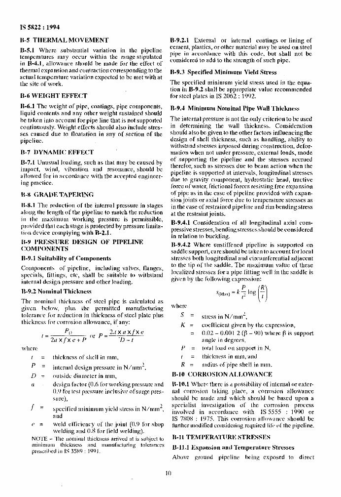
B-5.1 Whrre substautial variation in the pipeline temperatures may occur within the range stipulated in B-4.1, allowance should be made for the effect of thermal cxpansionand contraction corresponding to the actual tcnlpemture variation expected to be met with at the site of work.
B-6 WEIGHT EFFE( :T
B-6.1 The weight of pipe, coatings, pipe components, liquid contents and any other weight sustained should bc taken into account for pipe line that is not supported continuously. Weight effects should also include stres- ses caused due to lloatation in any of section of the pipeline.
B-7 I)YNAMIC: EFFECT
B-7.1 Unusual loading, such as that may be caused by impact, wind, vibration and resonance, should be allowed for in accordance with the accepted rngincer- ing practice.
B-X <;RAl)E TAPERiNG
B-8.1 The rcductiou of the internal pressure in stages along the length of the pipeline to match the reduction ~II 111c maxiniunl working pressure is permissible, provided that each stage is protected by pressure limita- tion device con~plying with B-2.1.
II-9 I’RESSIJRE DESIGN OF PIPELINE < :OMPONENTS
B-Y.1 Suitirldity of Components
Coiiipoiienls of pipeline, including valves, flanges, speciaIs, Fillings, etc, shall be suitable to withstand inlcrnal design pressure and other loading.
B-9.2 Nominul Thickness
The nomiual thickness of steel pipe is calculated as given below, plus thr pemittcd manufacturing tolcrancc for reduction in thickness of steel plate plus thickness liar corm&u allowance, if any:
P ,_&_ ‘) 2.lX~lXfXe
___ or P = -- 211 x J’x e + P ‘D - t
where
1 p:
thickness of shell in nm,
iiitcrna1 design pressure in ~/iiuiiz,
D = outside dianieter in nm,
61 design factor (0.6 for working pressure and 0.0 l’or lcsl pressure inclusive ofsurge pres- sure),
I‘= specified nlininiuru yield stress in N/um?, and
<’ = weld efficiency of the joint (0.9 for shop welding and 0.g for field weld&).
NOTE - The nominal thickness arrived at is subject to minimum thickness and miinufactuiing tolerances prcscri bed i II IS 3589 : 199 1.
B-9.2.1 External or internal coatings or lining of cement, plastics, or other material may be used on steel pipe in accordance with this code, but shall not be considered to add to the strength of such pipe.
B-9.3 Specified Minimum Yield Stress
The specified minimum yield stress used in the equa- tion in B-9.2 shall be appropriate value rcconmended for steel plates in IS 2062 : 1992.
B-9.4 Mininnm Nornillal Pipe Wall Thickness
The internal pressure is not the only criterion to be used in detemining the wall thickness. Consideration should also be given to the other factors influencing the design of shell thickness, such as handling, ability to withstand stresses imposed during construction, defor- mation when not under pressure, external loads, mode of supporting the pipclinc and the stresses accrued therefor, such as stresses due to beam action when the pipeline is supported at intervals, longitudinal stresses due to gravity component, hydrostatic head, tractive force of water, frictional forces resisting free expansion of pipe as in the case of pipeline provided with expan- sion joints or axial force due to temperature stresses as in the cast of restrained pipeline and rim bending stress at the restraint joints.
B-9.4.1 Comideration of all longitudinal axial com- pressive stresses, bending stresses should be c.omidered in relation to buckling.
B-9.4.2 Where unstiffcned pipclinc is supported on saddle support, care should be taken to account for local strcsscs both longitudinal and circumferential adjacent to the tip of the saddle. The maximum value of these localized stresses for a pipe fitting well in the saddle is given by the following cxprcssion:
where
s = stress in N/nun’,
K = coefficient given by the expression,
= 0.02 - 0.001 2 (13 - 90) where fi is support iIll@C iii degrees,
P = ~a1 load on support in N,
I = thickness in nun, and
R = radius of pipe shell in nm.
B-10 CORROSION ALLOW.4NCE
B-10.1 Where there is a possibility of internal or exter- nal corrosion taking place, a corrosion allowance should be nlade and which should IX based upon a specialist investigation of the corrosion process involved in accordance with IS 5555 : 1990 or IS 7SOS : 1975. This corrosion aIlowauce should be further nlodificd considering required lili: of the pipeline.
B-11 TEMPERATIJRE STRESSES
B-11.1 Expansion and Temperature Stresses
Above grnund pipeline being exposed to direct
10
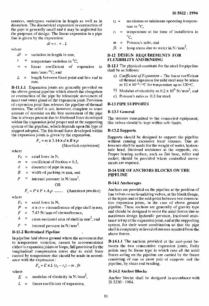
sunmvs. underrroes variation in length as well as in diantktc’rs. TheSiatnetrical expansiogor contraction of the pipe is generally small and it tnay bc neglected for the purposes of design. The linear ex’pansion in a pipe line is given by the expression:
d/=t.=.L
where
dl = variation in length in nun,
1 = temperature variation in ‘C, c1: = linear coefficient of expansion iii
tutiiitntii/°C, and
L = length between fixed point and free end in 111111.
B-11.1.1 Expansion joints arc gcncrally provided on the above ground pipelitte which absorb the elongation or contraction of the pipe by telescopic movement of inner and outer gland of the expansion joint. Provision ofcxpattsion joint thus releases the pipeline of thermal stresses. The relief is not, however, cotnplele as some amount of restraint on the free tnovetnent of the pipe line is always present due to frictional force developed within the expansion joint’proper and at the supporting system of Ihe pipeline, which depends upon the type of support adopted. The fricrional force developed within the expansion joints is given by the expression.
F,=mx3.14xdxBxp (Skoctiich expression)
whcrc
Fe = axial force in N,
m = cocfficicnt of f&ion = 0.3,
d = dia tnetcr of pipe in ttttn,
B = width of packing in nun, and
y = i ttternal pressure in N/nun’.
OR
Fe = POX F + A.p . . . . . . . . . (American practice)
whcrc
Fe. = axial force in N,
P = n x CJ = circumference of pipe shell in tntn, F = 7.43 N/mm of circumference, ’
A = cross-sectional area of shell in tntt?, and
1) = internal pressure in N/nun*.
Ii-U.2 Restrained I’ipeline
In pipelittc laid above ground where the movement due to temperature variation, cannot be accommodated either in expansion joints or loops, full provision for the longitudinal cotttpression stress due to axial force
_ caused by tctnperature rise should be made in accord- ance with the expression :
F,=ExL($-tl)-m.fll
where E = tnodulus of elasticity in N/inn?,
L = linear cocflicicttt of expansion,
IS 5822 : 1994
II, = tnnxitnuni or iuinitiiutn opcmting tettipcra-
ture in ‘C,
11 = temperalure at the titne of ittstallalion in
OC, III = Poisson’s ratio, and
fit = hoop stress due IO water in N/ttttu2.
B-12 DESIGN REQIJIREMENTS FOR FLEXIBILITY AND BENDING
B-12.1 The physical constants for the steel for pipeline shall be as follows:
a) Coeficient ofE.ipmkv7 - The linear coeflicient of thermal expattcton for tuild steel tray be taken as 12 X 10-6/0C for tctuperature up to 120°C.
b) Modulus ofelasticity as 0.2 x 10” N/n&, and
c) Poisson’s ratio as 0.3 for steel.
B-13 PIPE SUI’POM’L‘S
B-13.1 (;eneral
The stresses transmitted to the connected equipment, like valves should be kept within safe limits.
B-13.2 Supports
Supports should be designed to support the pipeline without causing excessive local stresses. Due al- lowance shall be made for the weight of water, hydros- tatic head, frictional resistance at the supports, etc. Proper bearing surface, such as flat base, roller and rocker, should bc provided where controlled niove- tncttls are required.
B-14 USE OF ANCHORS BLOCKS ON THE I’II’FLINE J
B-14.1 Anchorages
Anchors are provided on the pipeline at the position of line valves or sectionalizing valves, at the blank flange, at the tapers and at the mid-point between two consecu- tive expansion joints, in the case of above ground pipeline. These anchors are generally of gravity type and should be designed to resist the axial forces due.to tnaxitnutu design hydraulic pressure, frictional resis- tattcesetupatthecxpai~siottjoint,attdat~hesupporting system, for their worst combination so that the pipe shell is completely relieved ofstresses resulted from the above forces.
.B-14.1.1 The anchors provided at the tnid-point be- tween the two consecutive expansion joints, fixity points ntay be fratne type in which case all the axial forces acting on the pipeline are carried by (hc frame consisting of one or more pair of supports and the pipeline, by shear and bending.
B-14.2 Anchor Blocks
Anchor blocks shall bc designed in accordance with IS 5330 : 1984.
11
IS 5822 : 1994
ANNEX C ( Foreword )
CoMMITTEE COMPOSITION
Water Supply and Sanitation Sectional Conmittcc, CED 24
Chairman
SHRI v. I% I’ATEL
Members
ADWSER (PI-IE)
Detw~~ AnvtseR (PI II?) ( AItcrnute ) . SttRl M. S. &NAN1
SIIRVEYOR OF WoRKs III ( A Ilernale )
SttRt AvAnttFsti KUMAR DR S. GAONKAR (Alternate)
Smt I. S. IJAWWA
SttRl J. N. Clttose ( Altcrnute )
C’t ttw ENGINEER (PPRD) S;HRI v. K. ~LIPTA ( ~hmte )
SIIRI J. D. CRIII.
SttRt S. (;. ~hLAl_IKER
SHRI DEVENDRASING~~
StlRt H. (3. (jAR(i SttRt S. S. BOLA ( Alternutr )
h’DRALIl.lC’ EN( itNEER CttnF EN(4NPI.R (Si.Wt+ACiE PROJECX)
( AiGzrnafe)
SttRt F. LAL KAN~AL
SHRt M. M. KAt’OOR SttRt RANA PRATAP (Alternate)
Stat LALLAN~PR/\SA~
Sttu B. A. MALL~A
MANAGtNCi ~RK-KIR
l>R v. A. MttAtSALK/\R StrRt A. K. SETH ( Ahernale )
Stmt S. li. MUKHERIEE SttRt A. K. Dmr~ (Alternate )
SHR~ R. NATARAJAN SttRt B. P. MtsttRA (Alternate)
PROP K. J. i’htt SttRl I). GUIN (Alternate)
Stttu StstR K. NEAGI SttRt J. P. GIIPTA (Alternule )
(bL I-i. S. I’AI!L MAJ B. DAS (Alternate )
SHRt T. RAMACHANDRAN SttRt K. NAFRAJA~ (Alfernnte)
SttRt s. PRAKAstt SttRt S. S. Cwnnn~ (Alternate )
SECRE’IARY
SHRt L. R. SEHGAL
SttRt S. K. SItARMA
Start S. S. SRNASTAVA StiRt V. K. &PTA ( A /ternale )
’ In personal capacity (128 Munukbag Society, Ambawudi, Altmedabad)
Central Public Health Sr Ertvironmcntal Engineering Organization, Ministry of Urban Development, New Delhi
Public Works Department, Delhi Adtninistration
Tata Consulting Engineers, Bombay
Public Health Engineering Department, Madhya Pradesh
U. I? Jal Nigam, Lucknow
In personal capacity (B/SBA Gangotri Enclave, Alaknandu, NeM*Del/ti)
In personal capacity (Flut No. 40.3, Savhi Cinema (~‘ommcrcial Complex,
New Delhi)
In personal capacity (Anneye Building, 2nd Flooc DD-I, Kalkaji Extension,
New De&q
Haryana Public Works Department, Chandigarh
Municipal Corporation of Greater Bombay
Public Works Department, Public Health, Patiala (Punjab)
Engineers India Limited, New Delhi
The Institution of Engineers India, Calcutta
Northern Railway Headquarters, New Delhi
Punjab Water Supply & Sewerage Roard, Chandigarh
National Environmental Engineering Research Institute (<SIR), Maharashtra
Metropolitan Development Authority, Calcutta (West Bengal)
+Iindustan Dore, Oliver (India) Ltd, New Delhi
All India Institute of Hygiene and Public Health, Calcutta
Inslitutional Public Health Engineers, Calcutta
Directorate of Designs, Engineer-in-Chief’s Branch, Army Headquarters, New Delhi
Madras Metropolitan Water Supply and Sewage Board, Tamil Nadu
Delhi Water Supply Rr Sewage Disposal lrndertaking, Delhi
India Water Works Association, Bombay
L. R. Sehgal 6r CQ, New Delhi
Central Building Research Institute (CSIR), Roorkee
U. P. Jai Nigam, Lucknow
( Continued on page 13 )
12
1s 5822 : 1994
( C’on/inued Jrcm pge 12)
Members
SWWUNTENUING ENGINEER (DCC) IV SUKVllYoRoFWoRKS (DCC) IV
( A llernate )
SIRI H. N. ‘rAYN;ARAJA SWRI II. S. PU~TAKEMPANNA ( Allernale)
SIIRIS. v. WACili
SIIKI S. V. SHELKIKAR ( Alternate )
SHRI J. VENKATARAMAN, Director ( Civ Engg )
Hepresenting
Gntral Puldic Works Department, New Delhi
Bilngalore Water Supply & Sewage Ronrd, Karnat;rka
Maharashtra Water Supply 8.z Sewage~Project, Thane, Maharashtra
Director GeneA, HIS (kc-officio Member)
Member Secrelary
HEMANT K~JMAR
Joint Director ( CZiv Engg ), HIS
13
Brueau of Indian Standards
BIS is a statutory institution established under the Bureau of Indian Standards Act, 1986 to promote harmonious development of the activities of standardization, marking and qualit!‘ certification of goods and attending to connectedmatters in the country.
Copyright
BIS has the copyright of all its publications. No part of these publications may be reproduced in any form without the prior permission in writing of BIS. This does not preclude the free use, in the course of implementing the standard, of necessary details, such as symbols and sizes, type or grade designations. Enquiries relating to copyright be addressed to the Director ( Publications ), BTS.
Review of Indian Standards
Amendments are issued to standards as the need arises on the basis of comments. Standards are also reviewed periodically; a standard along with amendments IS reaffirmed when such review indicates that no changes are needed; if the review indicates that changes are needed, it is taken up for revision. Users of Indian Standards should ascertain that they are in possession of the latest amendments or edition.
This Indian Standard has been developed from Boc : No. CED 24 ( 5322
Amendments Issued Since Publication
Amend No. Date of Issue Text Affected
BUREAU OF INDIAN STANDARDS
Headquarters:
Manak Bhavan, 9 Bahadur Shah Zafar Mar-g, New Delhi 110002 Telephones : 331 01 31, 331 13 75
Telegrams : Manaksanstha ( Common to all offices )
Regional Offices : Telephone
Central : Manak Bhavan, 9 Bahadur Shah Zafar Marg NEW DELHI 110002
Eastern : l/14 C. I. T. Scheme VII M, V. 1. P. Road, Maniktola CALCUTTA 700054
Northern : SC0 445-446, Sector 35-C, CHANDIGARH 160036
Southern : C. I. T. Campus, IV Cross Road, MADRAS 600113
Western : Manakalaya, E9 -MtDC, Marol, Andheri ( East ) BOMBAY 400093
t 331 331 01 13 75 31
37 84 99, 37 85 61 37 86 26, 37 86 62
t 53 53 38 23 43, 84 53 16 4u
I 235 235 02 15 19, 16, 235 235 04 23 42 15
632 92 95, 632 78 58 632 78 91, 632 78 92
Branches : AHMADABAD. BANGALORE. BHOPAL. BHUBANESHWAR. COIMBATORE. FARIDABAD. GHAZTABAD. GUWAHATI. HYDERABAD.
JAIPUR. KANPUR. LUCKNOW. PATNA. THLRUVANANTHAPURAM.
Printed at New India Printing Prow. Khurja. India