is 12866 (1989): plastic translucent sheets made from ... · plastic translucent sheets made from...
TRANSCRIPT

Disclosure to Promote the Right To Information
Whereas the Parliament of India has set out to provide a practical regime of right to information for citizens to secure access to information under the control of public authorities, in order to promote transparency and accountability in the working of every public authority, and whereas the attached publication of the Bureau of Indian Standards is of particular interest to the public, particularly disadvantaged communities and those engaged in the pursuit of education and knowledge, the attached public safety standard is made available to promote the timely dissemination of this information in an accurate manner to the public.
इंटरनेट मानक
“!ान $ एक न' भारत का +नम-ण”Satyanarayan Gangaram Pitroda
“Invent a New India Using Knowledge”
“प0रा1 को छोड न' 5 तरफ”Jawaharlal Nehru
“Step Out From the Old to the New”
“जान1 का अ+धकार, जी1 का अ+धकार”Mazdoor Kisan Shakti Sangathan
“The Right to Information, The Right to Live”
“!ान एक ऐसा खजाना > जो कभी च0राया नहB जा सकता है”Bhartṛhari—Nītiśatakam
“Knowledge is such a treasure which cannot be stolen”
“Invent a New India Using Knowledge”
है”ह”ह
IS 12866 (1989): plastic translucent sheets made fromthermosetting polyester resin (glass fibre reinforced) [CED5: Flooring, Wall Finishing and Roofing]

IS 12866 : 1989(Reaffirmed 2003)
(11 q1i?~ C! 'Il-cx~ (Cf5t-q nn wrf.1c:r ) xl~~~ etr~ 'ilSG'I!-~
Indian Standard
PLASTIC TRANSLUCENT SHEETS MADEFROM THERMO-SETTING POLYESTER
RESIN ( GLASSFIBRE REINFORCED) SPECIFICATION
Second Repnnt OCTOBER 2007( lncludmg Amendment No I I
UDC 678 674 067 5-41
© BIS 1990
BUREAU OF INDIAN STANDARDSMANAK BHAVAN, 9 BAHADUR SHAH ZAFAR MARG
NEW DELHI 110002
June 1990 Price Group S
459: 1992
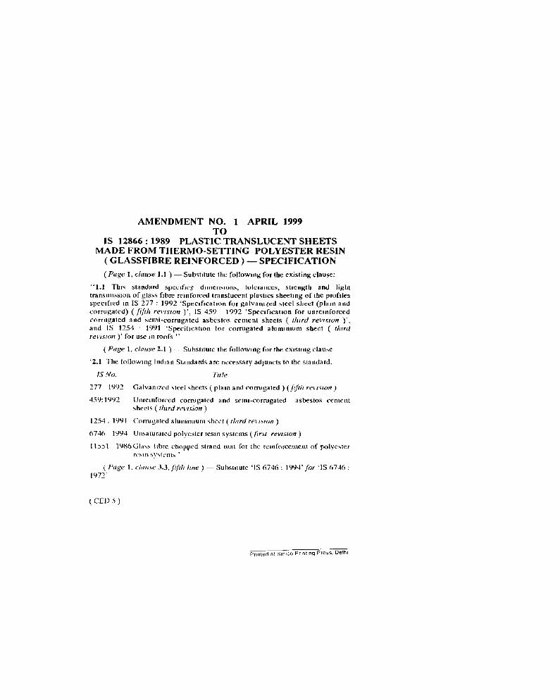
AMENDMENT NO. 1 APRIL 1999TO
IS 12866: 1989 PLASTIC TRANSLUCENT SHEETSMADE FROM THERMO-SETTING POLYESTER RESIN
(GLASSFIBRE REINFORCED) - SPECIFICATION
[Page 1, clause 1.1 ) -c--Subvtrtutc the following for the existing clause:
"1.1 TIll'> standard SIJCl.:lfll'::i dIIllCnSIOIl..'i. tolerances. strength and lighttransuussron of glass fibre reinforced translucent plasucs sheering of the profilesspecrfrcd m IS 277 : 1992 'Specsfrcanon for gulvaruzed steel sheet (ptaru andcorrugated) (fifth rCI'{SlOn)', IS 459 1992 'Spccrfrcauon for unrcruforccdcorrugated lind semi-corrugated asbestos cement sheets ( tlurd revision )',and IS 1254 IWI 'Specitrcanon for corrugated ajunnruum sheer ( ttnrdre~'/SlOn)' for use ,11 roofs ,.
c Page 1, ctanse 2.1) - Subsuturc tbe following for tbe exrsrmg clause
'2.1 The foflcwmg ludran Standards arc necessary adjuncts to the standard.
IS No. rot-
'277 199~ Galv;l1l17e'-.! vtccl "heels {plam and corrugated) (fifth rell~JO")
Uurcmforccd corrugated and scull-corrugated asbestos cementsheets (llllrd rrwsion)
1254. ]991 Corrugated alunumum sheer i tlurd retlHfJn)
67..tfl 1994 Un...arurarcd polyester rcsm systems ([tnt revrston s
11551 19~6Glo1""j., ubrc chopped strand mal for the rcuiforccmeut of polyesterrC'."1Il ~Y"(CIl1" '
(Page 1, dIl/LH:! 3.3, llfth line) - Subsututc 'IS 117..f6 : 1'N4' for 'IS 1)7"'6:1971'
( CElJ 5 )
Flooring and Plasterin, Sectional Committee, DOC S
FOREWOR.D
This Indiaa Standard was adopted by tbe Bureau or Indian Standards on 25 January 1989••ncr thedraft finalized by the Water Supply and Saoitation Sectional Committee had been approved by theCivil Engineering Division Council.
This standard deals with the quality, performance and overall dimensioDs ofglassfibre reinforcedcorrugated translucent sheeting for buildm8 purposes, It includes sheeting of all profilca given inIS 277 : 1985 'Specification for galvanezed steer sheets (plain and corrugated) (fourth rmsion ,'.IS 459 : 1970 'Specification for unreinforced corrugated and semi corrugated asbestos cement sbeets( second revision )', and IS 1254: 1975 'Specification for corrugated aluminium sheet (suond rellistonI",For the preparation of this standard, considerable assistance bas been derived from BS 4154 ( Part I ):1985 'Specification for corrugated plastic translucent sheets made froID. thermosetting polyester resin( glasefibre reinforced Y. issued by the British Standards Institution. U.K.
For the purpose of deciding whether a particular requirement of Ihis standard is complied with, thefinal value. observed or calculated. expressins the result of a test or .oalysis. sball be rounded off In
accordance with IS 2 : 1960 "Rules for rounding off numerical values l nV;.Jedy. The number ofsignificant places retained in the rounded off value should be the lame as that of tbe Specified valuein this standard.
IS I~: 198t
Indian Standard
PLASTIC TRANSLUCENT SHEETS MADEFROM THERMO-SETTING POLYESTERRESIN ( GLASSFIBRE REINFORCED)
SPECIFICATION
3.2 The glassfibre used as remforcement s1:lal1 beIn the form of chopped strand mat having a tughlysoluble tnodrfied polyester binder in accordancewith IS 11551 : 1986 having B density of 450 81m'and minimum width of 500 mm.
3.3 Special grade of unsaturated polyester resinhaving a refractive index matching that of theglassfibre ( that IS 1-53) and conformmg to thebroad specificanons given below shall be used.The methods of testing the resin properties shallbe in accordance with IS 6746 : 1972 (Physicaldata in liquid state);
a) Viscosity at 25cC, in cps : 400 to 500( Brooke-field LVF spindle2/12 rev per min)
4 PROFILES, DIMENSIONS ANDTOLERANCES
4.1 ProW..
The profile of the sheet shall match the profilesspecified in the approprrate Indian Standard forthe particular material as given m Table 1 whichwill surround the translucent sheets.
4.1 The dimensions of the sheets are Biven mTable I.
4.3 Sheets With higher thickness than that specified in Table I may be made as agreed betweenthe purchaser and manufacturer.
4.4 For the purpose of measuring thickness. athickness gauge shal! be wed and it sball bemeasured at least at 10 random points on all thefour Sides and the average value shall be taken.
4.5 The depth of each of the corrugations shallbe measured on the smcoth stde and the maximumdeviation 10 any of the cases measured. shaU Dotexceed the limits specified 10 Table I.
1 SCOPE
1.1 This standard specifies dimensions. tolerances,strength and light transmission of glassfibrereinforced translucent plastics sheeting of theprofiles specified in IS 277 : 1985 'Specificationfor galvanized steel sheet ( plain and corrugated)<fourth revts Ion ). IS 459 : 1970 'Specification forunrcioforced corrugated and semi corrugatedasbestos cement sheets (second rell/ston)' andIS 1254: 1975 'Specification for corrugated aluminium sheet ( second rnu;on )' for use in roofs.
1.1 The recommended temperature range overwhich the sheets can be used as roof lights or forglazing should be from - 20 to +{j()°C.
1 REFERENCES
2.1 The following Indian Standards are necessaryadjunctl to this standard:
IS No. rut«277 : 1965 Galvanized steel sheets {plam and
corrugated ) (fourth revision)
459 : 1970 Unreinforced corrugated and semicorrugated asbestos cement sheets( second revision)
1254: 1975 Corrugated aluminium sheet( second revision)
6746 : 1972 Unsaturated polyester resin systemsfor low pressure fibre reinforcedplastics
11551: 1986 G1a.. fibre chopped strand mat fortho reinforcement of polyesterresin system
3 MATERIAL
3.1 The material shall be composed of a thermoletting styranated or acrylated polyester resinsystem remforeed with glasafibre, This system mayinclude curing agents, catalysts and light stabrHzen. Fire retardant grade of resin and colouringmatter may be used only in special cases as agreedto between the purchaser and the manufacturer.
b) Specific gravity at 20Gec) ACid number, in mg KOH/g
d) Solids. 10 percent
: 1 11
: 2S to 30
: 65
IS 1Z86li : 1m4.6 For the determining the pitch of the corrugation. total1cogth over 6 pitches shall be measuredand tbe length measured over these 6 pi tcbes shallDol vaT)' from 6 lime tbe .peo,fied pitcb by lb.tolerance. aiven ia Table 1.
5 WOIlKMANSHlP AND PlNISH
S.t The sheets sball have a smooth surface finishon both sides. A resin rich surface oa the exposedpart of the sheet IS necessary to ensure that the.heer has good weathering pFopertiei.
5.% The moulded sheets shall be reasonably freefrom visible defects, such as. fibre pattern, foreigninclusions. cracks, crazing, die-lines, pin holes.striations, and bubbles Over 1"3 mm in diameter.
5.3 Special Floi.....
A clear tissue of fibregfass surface mat or polyestermat may be applied to the sheet surface (on theside exposed to weathering) during manufactureto improve resistance to weathering Alrernelively, PVF and polyester eladdmg films can bebonded to the sheet surface ( on the SIde exposedto weathering) during manufacture to provideexcellent weathering and chemical resistance andlonger life
6 PERFORMANCE REQUIIlEMENI'S
6.1 Dea"lJThe Dominal weigbt of ]·10+0·15 mmlbick plaiDsbeet shall be I'S5 kll sq m.
6.1 GlusC_
The glass content in the laminate shall not be lessthan 30 percent when tested in accordance williAnnex A.
6.3 Water AbsorptioD
The sheets shall not absorb water in excess of0'3 percent when tested in accordance wjtbAnnex B.
6.4 Hordo... ( Ba.....1 )
When the sheets are tested with the method givenIn Annex C. the Barcol hardness shall not increase by more than 30 percent or its initialvalue.
6.S Bolt Sbear Tell
When tested in accordance with Annex D, thearithmetic mean of the loads at which the firsttear appears, shall be not Jess than 375 N. Theload at which the first tear appears while testingany one of the specimens, shall be not less than2;0 N.
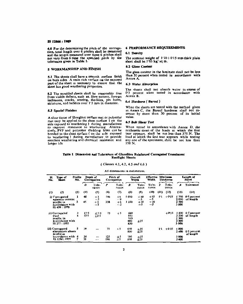
Tabl. 1 DimensloD ADd Tolerances of Glass6bre Reinforced Corrugated TI'aDS'aceotRootlight Sileets
(C/au"s 4.1,4.2,4.5 and 4.6 )
All dtmensrons IQ munmetres.
sr T)"Je of Profile Depth of Pilch of O'erall Eft'ectlu Minim.. Length ofNo. Sbee' No. COrrtlRatla. CorruKatlqa Wldtb Width Thll"koe.. Shret
.~----.Tole::
, . , .D Tole. P Tole- R Tole. T Tole-- " Tolerance
ranee ranee ranee ranee: ranee
(I) (2) (3) (4) (') (6) (7) (8) (9) (10) (II) (12) (13) (14)
i) COrfUl8ted I 48 +3 146 +6 10S0 +10 +lO ('1 +O"U 1 7'" 0-5 percental5besto!l cement -, ~9 -, -, 2000 of lCDltbprofile in 2 4' +3 338 +6 I tOO +lO +10 2300acccrdeece with -3 -2 -, -j 3000IS 459: 1910
ii) Corruia tcC: 3 I7'S ±2'S 73 +' 660 +0'15 1800 0·5 percentatee l 4 12'5 ±2'S 81O 2200 of lCDltbprotilc in 910 2300accordance with 68O ±23 2800IS 277 : 1985 .30 3000
iii) Corrugated S 19 73 +' 6,0 ±23 t't +0 IS 1800aluminium .heels '00 '0 23 2_ 0'5 percentprofile ID of lenltbaccordance with 6 3. 12' ±, 7'" ±2' 3000IS 1254: 1975 7 38 190 ±3 830 ±23 3600
2
IS IZlI66 : 1.,
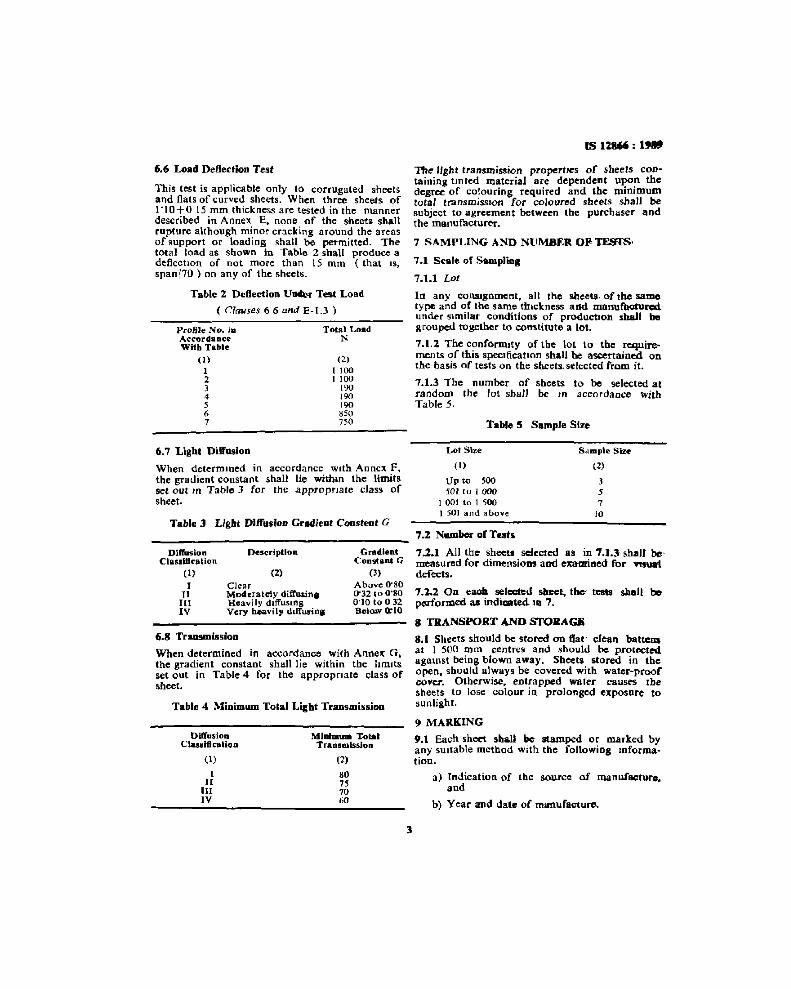
6.6 Load Deflection Test
This test is applicable only to corrugated sheetsand flats of curved sheets. When three sheets of1-10+015 mm thickness are tested in the mannerdescribed in Annex E. none of the sheets shallrupture although minor cracking around the areasof support or loading shall be permitted. Thetotal load as shown in Table 2 shall produce adeflection of not more than 15 mm (that IS.
spanl70) on any of the sheets.
Table 2 DcOection U..., Test Load
( Clauses 6 6 and E-I.3 )
Profile No. juAccordanceWith Table
(J)
)
234567
Total LoadN
(2)
11001 100
190190190850"0
The' light transmission propertses of sheets containing tmred material are dependent upon thedegree of colouring required and the minimumtotal transmission tor coloured sheets shaJl besubject to agreement between the purchaser andthe manufacturer,
7 SAMPLING AND NUMBER OF>TES'I'S'
7.1 S<&lo of 5_,llog
7.1.1 Lot
In any consagnment, all the sheets. of the sametype and of the same ttnckness add manufaoturcdunder SImilar conditions. of prcducnon shall begrouped together to constitute a lot.
7.1.2 The confcrmrty of the lot to tbe requirements of this specaficatton shall he. ascertained onthe basis of tests on the sheets. selected from it.
7.1.3 The number of sheets to be selected atrandom the Jot shall be In accordance withTable 5.
Table 5 Sample Size
Table 4 Minimum Total Light Traosmissioo
Table 3 Light DitrusWn GrlHlieot CODsteot G
6.8 Transmission
When determined in accordance with Annex G.the gradient constant shall lie within the limitsset out in Table 4 for the apprcprtate class ofsheet.
6.7 Lighl DilJusioo
When determmed in accordance with Annex F,the gradient constant shall lie withm the limitsset our In Table 3 for the .appropnate class ofsheet.
Sample Siu
(2)
357
10
Lot S'ze
( I)
Up tv 500501 [0 I 000
1 001 to I 5001 501 and above
7.2 Nombel" of T..t.
7.2.1 All the sheets selected a. in 7.1.3· shall bemeasured for dimensioes aed examined for T'fSUIIidefects.
7.1.2 00 <aOIO seteaed wet, tilt IcIIta shall beperforreed .. indicated I. 7.
8 TRANSPORT AND sroRAGIi
8.1 Sheets should be stored on 8at~ clean battenaat 1 500 mm centres and should be protectedagainst being blown away. Sheets stored in theopen. should always be covered with water-proofcover. Otherwise. entrapped water causes tbesheets to lose colour in prolonged exposure tosunlight.
9 MARKING
9.1 Each sheet .ball be Ramped or marked byany SUitable method with the following mformation.
a) Indication of the source of manufacture.aod
b) Year and dale of reenufacture,
GradientConstlLnt G
(')Above O'SO0"32 to 0·800'10 to 0 32Belo.w 0:10
(2)
80757060
MIIIIlIIum "l:olalTraollwlssion
ClearModeratc1y diffusinlHeavi Iy diffUSingVery heavily dlffurin&
(2)
Description
(1)
III
IIIIV
DiffusioaClasrd8eatlOD
DiffusionCiassl8eaUoo
(1)
I11111IV
IS 12B'6 : J!I8~
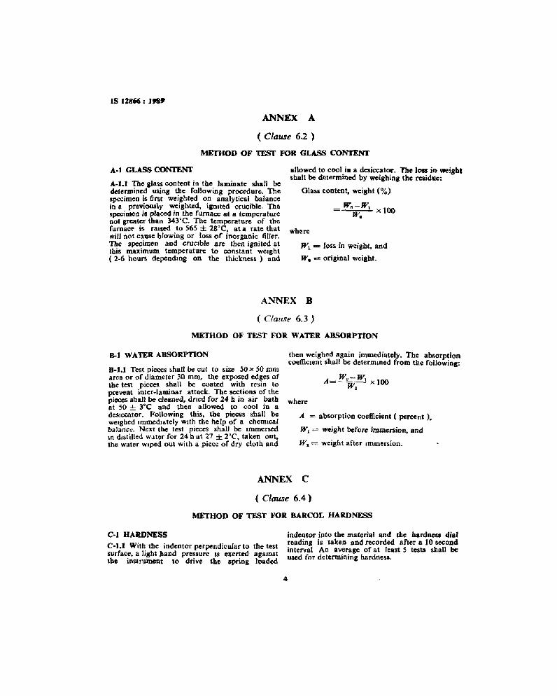
ANNEX A
( Clause 6.2 )
METHOD OF TEST FOR GLASS CONTENT
A-I GLASS CONTENT
A-t.1 The &Iasscontent in the laminate shan bedetermined UiiOB the following procedure. Thespecimen is first weighted on analytical balancein 8 previously weighted, igolted crucible. Thespecimen is pieced in the furnace at a temperatureDot greater than 343~C. The temperature of thefurnace is raised 10 565 ± 28"C, at a rate tbatwiU not cause blowing or loss of inorganic filler.The specimen aed crucible are then ignited atthis m..ximum temperature to constant weight( 2-6 hours depending on the thickness) and
allowed to cool in a desiccator. The Joss in weights.haH be determined by weigbing: the residue:
Glass content. weight (%)
_~"'';;-'''W''--'-' x 100W.
where
W1 .... loss in weight. and
We s::o: original weight.
ANNEX B
( Clause 6.3 )
METHOD OF TEST FOR WATER ABSORPTION
11-1 WATER ABSORPTION
8-1.1 Test pieces shall be cut to size 50 x 50 romarea or of diameter 30 mm, the exposed edges ofthe test pieces shall be coated with resin topreveot inter-laminar attack. The ~tion.s of thepieces shaH be cleaned. drted for 24 b In aIr batbat 50 ± 3°C and then allowed to cool in adesiccator, Following tbis, tbe pieces shall beweighed Immediately With the help of a chemicalbalance. Next the test pieces shall be ImmersedIn distilled water for 24 h at 27 ± rc. taken out.the water WIped out with a piece ordry cloth and
then weighed again immediately. The absorptionccefflcrent shall be determined from the following:
W2-WA= -- __1 X 100W,
where
A = absorption coefficient ( percent ).
WI = weight before immersion. and
W,- = weight after Immersion.
ANNEX C
( Clause 6.4)
METHOD OF TEST FOR BARCOL HARDNESS
C-I HARDNESS
C-I.t With the indentor perpendicular to the testsurface. a light hand pressure IS exerted 3gamstthe instrument to drive tbe spring loaded
indentor into the material and the hardness dialreadins is taken and recorded after a 10 secondinterval An average of at ICBst S testa shall beused for determining hardness.
4
IS 12866 : 1919
ANNEX D
( Clause 6_5 )
METHOD OF TEST FOR BOLT SHEAR TESr
D·I BOLT SHEAR TEST
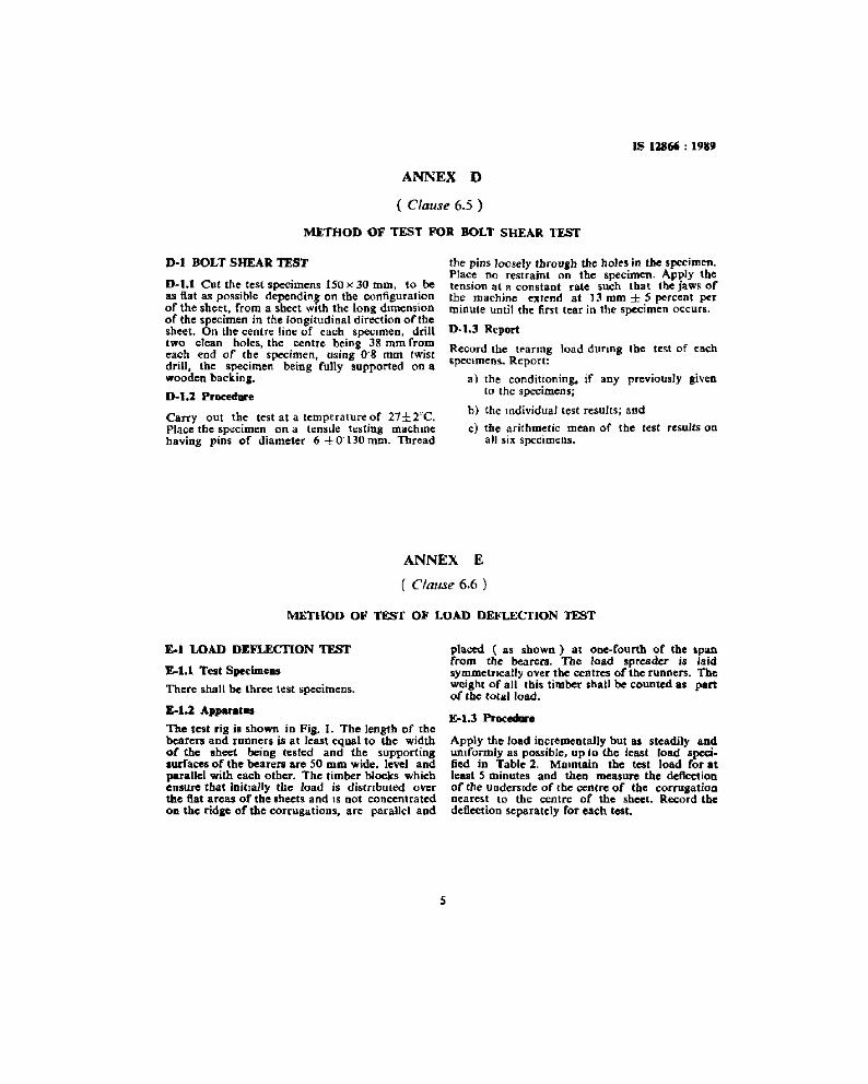
D-1.1 Cut the test specimens 150 x 30 mm. to beas fiat as possible depending on the configurationof the sheet. from a sheet with the long dimensionof the specimen in the longitudinal direction of thosheet. On the centre line of each specimen, drilltwo clean holes, the centre being 38 mm fromeach end of the specimen, using 0"8 mm twistdrill, the specimen being fully supported on awooden backing.
D-l.1 Procedure
Carry out the test at a temperature of 27±2cC.
Place the specimen on a tensile testing machmehaving pins of diameter 6 -±- 0"130 mID. Thread
the pins loosely through the holes in the specimen.Place no restraint on tbe specimen. Apply thetension at a constant rate such that the jaws ofthe machine extend at 13 mm ± 5 percent perminute until the first tear in the specimen occurs.
D-1.3 Report
Record the tearmg load dunng the test of eachspecimens, Report:
a) the conditioning. if any previously givento the specimens;
b) the Individual test results; and
c) the arithmetic mean of the test results 00
all six specimens.
ANNEX E
( Clause 6.6 )
MEmOD OF TEST OF LOAD DEFLECnON TEST
£.1 LOAD DEFLECTION TESr
£.1.1 Test Spe<lme..
There shall be three test specimens.
£.1.2 A,......I..
The test rig is shown in Fi8. 1. The length of thebearers and runners is at least equal to the widthof the sheet being tested and the supportingaurfaces of the bearers are 50 mm wide. level andparallel with each other. The timber blocks whichensure that initially the load is distrrbuted overthe aat areas of tbe sheets and IS not concentratedon. the ridae of the corrugations. are parallel and
5
placed ( as shown) at one-fourth or the spanfrom the bearers. The load spreader is Jaidsymmetrically over tbe centres of the runners. Theweight of all this timber shall be counted as partof lhe lOla' load.
E-1.3 Procedure
Apply the load incrementally bUI.. steadily andumformly as possible. up io the least load specified in Table 2. MalDtain the test load for atleast 5 minutes and then measure the deflectionof the underside of the centre of the corrugationnearest to the centre of the sheet. Record thedeflection separately for each test.
IS 121641-: I,.,
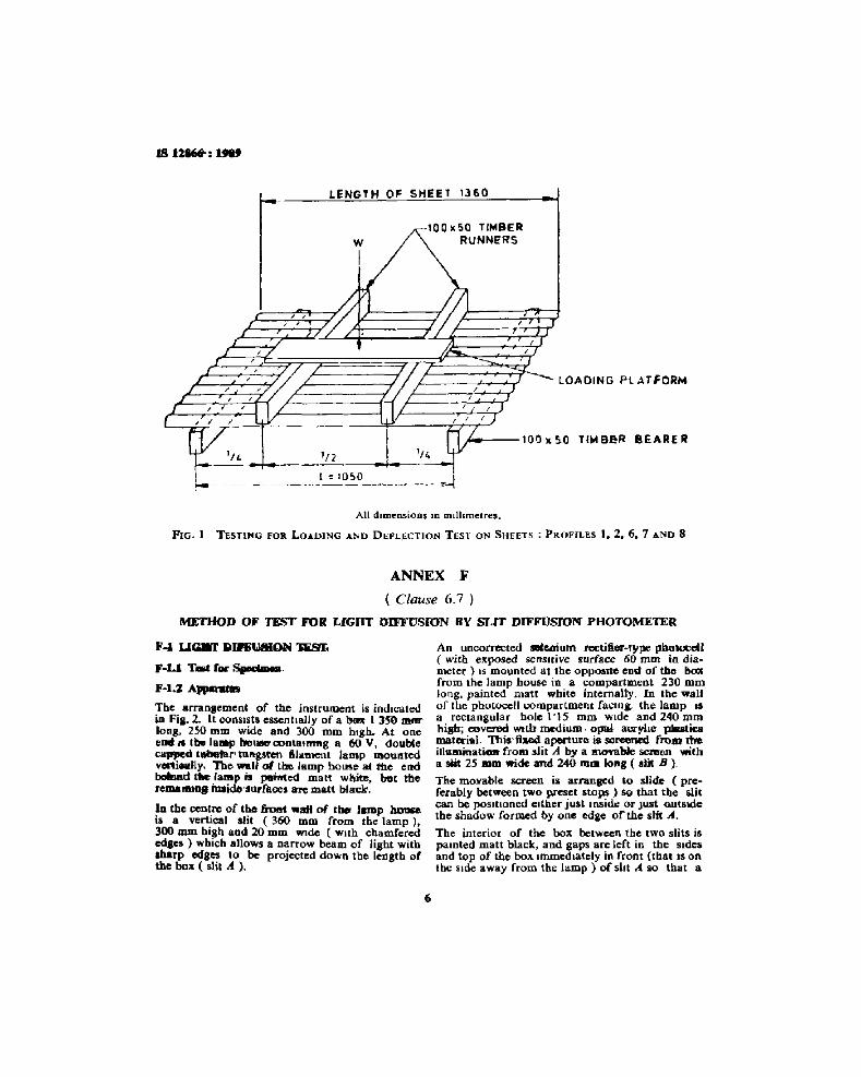
LENGTH OF SHEET '360
wI
'nt :::. lO~O
100 .50 TIMBERRUNNERS
",,"0---100.5.0 TIMEU!R BEARER
All dimensions In rmlhmetres,
FIG. I TESTING FOil LOADING AND DEFLj:OCTION TEST ON SHEETS: PROFILES 1.2.6.7 AND 8
ANNEX F
( Clause 6.7 )
METHOD OF TEST FOR LIGHT DIFFUSION BY SLIT DIFFllsrON PHOTOMETER
Fool UaM 91RUAlC»l D:SIr.
F-Ll T_ r Spodmoa.
F-I.ZA..........
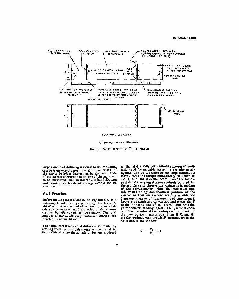
The arrangement of the instrument is indicatedin Fig. 2. It consists essentially of a bO'X I 350 JDIII"
long. 250 mm wide and 300 rom high. At oneeDlllI'I tb. lalap blDU!M:l' contlurrmg a 60 V. doublecappeo tdibetar l tuegseen ilv:nacnt lamp mountedvorti..Ily, lbe waU 01 tee lamp bOlKC at tbe endbClIrmd dw lamp is peirtted matt white, bat tbereDlarDHIgiutido'surfiLees are matt black.
In tbe centre of tbe _ ..all of tboo llIDlp _is a vertical slit (360 mm from the lamp ).300 mm bigh ecd 20 rom wide (with chamferedcdSes ) which allows a narrow beam of light withsharp edges to be projected down the length ofthe box ( slit A ).
6
An uncorrected sKeaium rectiior~tyIJe pholOCeU(with exposed seesmve surface 60 mm in dieOlder) IS mounted at the opposae end of tbo boxfrom the lamp house in a compartment 230 mmlong, painted matt white internally. In the wallof the photocell compartment facing. the lamp ISa rectangular bole: 1"15 mm Wide and 240 mmhigh; CDvcnxl: WIth medium opal acryhc piluticsmattl'i.l. This·fhed aperture is screened from theillummatiGR froID slit A by a ftl0'Y8.bk: semen witha stit 2S IDIlI wide and 240 mm IoBg ( alit B ).
The movable screen is arranged to slide (preferably between two preset stops ) SO that the slitcan be posmoned enher just Inside Or Just cnrsscetbe shadow formed by one edge of the slit A.
The interior of the box between the two slits ispamted matt black, and gaps aTCleft in the Sidesand top of the box unmediately in front {that IS onthe Side away from the 111.mp ) of slit A. so that a
1S)1I6/i:~
lIIl~UT WHITE INDWAll. lItESJ MATT.lACK INTE~N"U't
iO W fUBUlHtLAMP
ILLUMINATING SLIT lA,10 WIDE. lOQ HI GH WITt-tCHAMFERED eo ees
SAMPLE {MEASURED WITHCORRUGATIONS AT RIGH1' ANGLESto LENGTH OF SlJTJ
76'
ALL NATT BLACKiNfERNAllY
MOVEABLE SCREeN WlT H SUT2'!1 WIDE ICHAt,"'F"eREO EDGES IALTERNATIVE POSITION SHOWN
O()llEDSEC TlONAL "lAN
,:8 LINE OF SHAOOW FRO,,", ~~;
ILLUMINATING SL'-'--SAMPLE
OP4l PLASTICSSOI£ EN
UNCO~fJECTEO PHOTOCelL(iQ orAMETER WORMING
SUF;!f:ACE)
ALL ""'A1T WH1TEINT{RNAltr
SECTIONAl.- ElE.VATION
All dunensrons m mnttmetres.
FIG. 2 SLIT DIFFUSION PHUTOMETER
large sample of diffusing material to be measuredcan be traneversed across the silt. The Width ofthe gap to be left is determmed by the amphtudeof the largest corrugation. on any of the matersalato be measured and In thrs way, a band JOu mmWide around each Side of ol. large sample can beexamined.
F-l.3 Pro"",,ur.
Before making measurements on any sample. It isD~ssary to set the stops governmg the travel ofslit B. so that at one end of its travel. one of lts~dgts is c01Rcidenl witb the edge of tbe sbadowthrown tty slit...4. and at rbe shadow. The totalamount of travel, allowmg sufficient margm foroverlap, IS about 30 mm.
in tbe slot (with corrugations fUDOin. borizontallr ) and the movabJe screen ia set alternatelyagainst ODe or the other of the stops limltlDg itatravel. With the sample Immediately in From ofsht A, and slit B 10 the beam. move the samplepast slit A. ( keeping it always entirely covered bytbe sample) and observe the variations in readingof the galvanometer. Note the maximum Uldmirnmwn readings and choose a position of thesample so that an average readmg IS obtained( aruhmeuc mean of miJumum and maximum).Leave the sample In ttns posillon and move slit.llto the OPPOSIte end of ItS travel. and Dote tbegalvanometer reading again. The gradient constant C IS the ratio of the readings wrtb the alit inthe two position, mmus one. Thus if Rb and R i
are the readings with the silt B respectively lD tbebeam and In the shadow.
The ~tual measurement of dnfusrcn IS made byrelating readmgs of a galvanometer connected 10the photocell when the sample under test IS placed
1
IS U8" : 1989
ANNEX G( Clouse 6.8 )
G-I ME,,"SUREMENT OF TOTAL LIGHTTRANSMISSION BY INTEGRATING BOXPHOTOMETJi;R
G-I.I TOft for Spe<lmeD
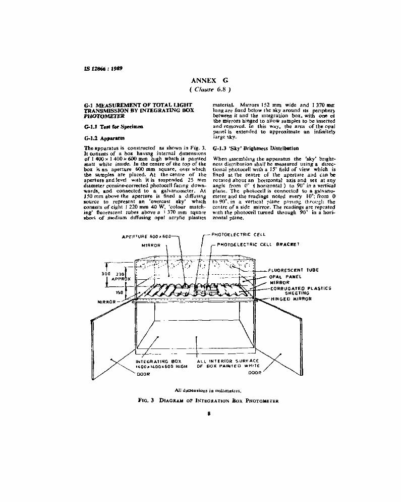
G-I.:1 ""pp.......
The apparatus is constructed as shown in Fig. 3.It consists of a box havmg internal drmenstonsof I 400 x 1 400)( 600 mm high whtch is pamtedmatt while insrde. In the centre of the top of thebox is an aperture 600 mm square, over whichthe samples are placed. At the centre of theaperture and level with it is suspended 25 romdiameter consine-corrected photocell facing downwards, and connected to a gal vanometer . AtISO rom above the aperture is fixed a drffusmgsource to represent an 'overcast sky' whichconsists of eight J 220 mm 40 W, 'colour matching' fluorescent tubes above a I 370 mm squaresheet of medium diffusing opal acrylic plasncs
M'RRO~-
material. Mirrors 152 mm. wide and 1370 mn:lang are fixed below Itie sky around Its pertpherybetween it and the mtegraticn box. with one 01the mirrors binged to alJow samples to be insertedand removed. In this way. the area of the opalpanel is extended to approximate an infiflitel~
large tkY.
G·l.3 'Sky' Brightness Distrlbullon
When assembling the apparatus the 'sky' brightness distribution shall be measured using a directional photocell with a 15° field of view which isfixed at the centre of the aperture and can berotated about an honzontal axis and set at anyangle from 0° (horizontal) to 90'" in a verticaJplane. The photocell is connected to a galvanometer and the readings noted every 10°; from 0to 9ft, in a vertical plane pas.'Hug. through thecentre of a side mirror. The readings are repeatedWIth the photocell turned through 90" in a horizontal plane.
PHOTOelECTRIC CELL
":":'~' :. (: :,
- - ~ ~ - -\..
INTEGRATING BOX.400 1I14QOlL600 ttlGH
DOOR'
ALL INTERIOR S.URFACEOF BOX PAI....tEO wHiTE
DOOR
All d.IDeQsioQS ip nun.metres,
FIG.3 DIAGR.&.M OF INTEO&ATlON Box PHOTOMETER
s
IS 11866 : 1989
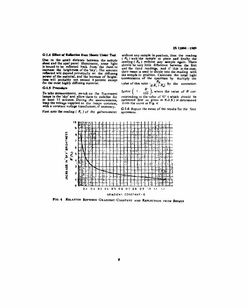
G-J.4 meet et RolIo<tlaol from _ U_ Toot
D1Ie to tb• ..".11 distance betweeD the lamp"Meet and the opal panel illuminator, some lightis bound to be reflected back: from the sheet toiQlClU.Je the bri,htnesl of the 'sky'. The amountreflected will depend principally on the diffUSingpower of the material, and the increase of bri.bt0 ... will probably Dot exteed 4 percent exceptfor the: moat hiJbly dilfurina material.
G-J.5 I'ro<Mare
To take measurements. awnch on the fluorescentlamPl in the 'sky' and allow them to stabilize forat leu. J5 minutes. DUTi~g the measurements.keep the voltage eupphed ro the lamps constant,with a conatanl voltase transformer, jf necessary.
Fint note l.be nadinB ( R1 ) of the galvanometer
without any sample in position. then the rcadlDg( R. ) WJtb the sample In place aDd finally tbereading ( R.) Without any ample Blain. Thereshould be very little difference between the firstBod the third readings, and if this is the case.their mean is used to divide into the reading withtbe sample in position. Calculate the totel lighttransmission of the specimen by multiply the
value oftbis ratio 'l(R,~Rs)
by the correction
factor ( }o= 16-:5 ). where the value of D' cor
responding to the value of 'G' (which should bemeasured first as gi"en In E-J.l) ,s determinedfrom the curve 10 Fig. 4.
G~J.6 Report the mean of the results for the fourspecimens.
I : '.
" I:, , .
t '. ,.1'I 'J J "
,. ',,"
, "'I,:I! ,'I, .': :,1
1'. :'1
" " ill.II 'I!. .1
, '_.I~.!' 'I I. ".• ., f4i
" ,,'1,',1.1'. I, lew.,;.
, .. ,I,. ,
! 1-; ",,
"I"
,
", I,-J
,
'" "., ,
-': ,
- I"-
,! :r.
"".-..r ..r
'"" '"
• i,
:=..OM.....z
1D ,I' i~. 'I: ",'.,
0.1 0-2 0·3 0' 0') 0-6 0-7 0·8 09 1.0 I., 1./
GR AorEN T CONST AN T - G
p(O~ 4 RELATION BETWBEN GRA.DIENT CONSTANT AND RBPLECl'lON FROM SHEBTJ
,
Bureau of Indiao Standards
BIS IS a statutory msutuuon estabhshed under the Bureau of Indian Standards Act, 1986 to promoteharmonious development of the acuviues of standardazatron, marking and quahty cernficatron of goods andattending to connected matters rn the country
Copyright
BIS has the copynght of all Its publrcanons No part of these publications may be reproduced In any formwithout the pnor pernussson In wntmg ofBIS This does not preclude the free use, In the course ofunplementmgthe standard, of necessary details, such as symbols and Sizes, type or grade dcssgnauons Enqumes relating tocopyright be addressed to the Director (Pubhcanons). HIS
Review of Ind ian Standard"
Amendments are ISSUed (0 standards as the need anses on the basis of comments Standards are also reviewedpcnodrcallv a standard along With amendments IS reaffirmed when such review Indicates that no changes areneeded. If the review mdicates that changes are needed. It IS taken up for revision Users of Indian Standardsshould ascertain thatlhey are In possession of the latest amendments or edition by refemng to the latest Issue of'815 Catalogue' and .Standards Monthly Addrttons'
Thts Indian Standard has been developed from Doc No CED 5 (4462)
Amendments Issued Since Publication
Amend No Date of Issue Text Affected
BUREAU OF INDIAN STANDARDS
{260 3S432609285
{2254 1216,225414422254 2519, 2254 2315
{2832 9295, 2S32 785S28327891,28327892
Telephones
{2323 76 1723233841
{2337 8499, 2337 S56123378626, 2337 9120
C JT Campus, IV Cross Road, CHENNAI600113
Manakalaya. E9 MIDC, Marol, Andhen (East)MUMBAI 400093
1/14 CIT Scheme VII M. V I P Road, KankurgacluKOLKATA 700054
SCO 335-336, Sector 34-A, CHAND1GARH 160022
Manak Bhavan. 9 Bahadur Shah Zafar MargNEW DELHI II 0002
Western
Northern
Eastern
Southern
Central
Headquarterv:
Manak Bhavan. 9 Bahadur Shah Zafar Marg, New Deihl 110002Telcphone-; 2'121013 L 2123 1175. 2323 9402 websue www bts org m
Re~ional Offices;
Bunches AHMEDABAD BANGALORE BHOPAL BHUBANESHWAR COIMBATORE FARIDABADGHAZIABAD GUWAHATl HYDERABAD lA/PUR KANPUR LUCKNOW NAGPURPARWANOO PATNA PUNE RAJKOT THIRUVANANTHAPURAM VISAKHAPATNAM
Pnnt.ed "I Simco Pnnlmg Press, DeJIn