irrigation water conveyance - pipelineirrigation water conveyance – pipeline basic requirements:...
TRANSCRIPT

IS-6
(IS-6) Achieving Irrigation Water Management (IWM) With Irrigation Water Conveyance – Pipeline
Basic requirements: Benefits:
Irrigation pipelines come in a variety of diameters (4” to Increases efficiency of water delivery from well
24” are the most common) and a variety of materials to point of irrigation.
(Poly Vinyl Chloride, Steel, Non-reinforced concrete, and Maintenance is minimal compared to an earthen
Aluminum). ditch or concrete lined ditch.
Irrigation pipelines are used with sprinklers, drip systems, Will work on any field, regardless of shape.
and flood applications on a variety of crops.
Photo From Ft. Sumner FO
24” PVC Pipe

IS-6
Page 2 Table Of Contents
Page # Title Purpose
1 Achieving Irrigation Water Management (IWM) with Irrigation Pipelines
To describe the basic requirements and benefits obtainedwith irrigation pipelines
2 Table of Contents Table of Contents
3 Friction Loss Table Example of friction loss table to assist in sizing irrigation pipeline
4 Pump Discharge Assembly To show valves on a typical pump discharge assembly
5 Typical Pump Discharge Assembly To show typical set up of valves for a pressurized irrigation pipeline at the well assembly
6 Pump Dogleg Assembly To show typical pump dogleg assembly
7 Typical Gravity Discharge Assembly To show typical gravity discharge assembly
8 Pipe Markings To provide explanation of typical pipe markings
9 Tee & Elbows To show tees and elbows in an irrigation pipeline system
10 Thrust Blocks To show typical types of thrust blocks
11 Minimum Depth of Cover To show minimum depth of cover for different sizes
12 Documentation of Depth of Cover Photo verification of depth

IS-6
Page 3 Friction Loss In Plastic Pipe (Ft / 100 Ft)(example)
Diameter In Inches
8 8 10 10 12 12 15 15 18 18
FlowGPM
FlowCFS
VelFt/sec
Hf VelFt/sec
Hf VelFt/sec
Hf VelFt/sec
Hf VelFt/sec
Hf
450 1.00 2.865 0.330 1.833 0.101 1.273 0.038
600 1.33 3.820 0.588 2.445 0.179 1.698 0.068
900 2.00 5.730 1.322 3.667 0.402 2.546 0.152
1500 3.33 9.549 3.672 6.112 1.118 4.244 0.423 2.716 0.129 1.886 0.049
2000 4.44 8.149 1.987 5.659 0.752 3.622 0.229 2.515 0.087
2500 5.56 7.074 1.175 4.527 0.358 3.144 0.135
3000 6.76 5.432 0.515 3.773 0.195
4000 8.89 7.243 0.916 5.030 0.346
To properly size the pipeline diameter, choose a velocity less than 5.0 Ft/sec and a friction loss (Hf) equal to, or less than, 1.0 Ft/100 Ft. Friction loss will vary based on pipe material, pipe diameter, change in elevation, and flow rate.
Note: Cubic Feet Per Second (CFS) x 450 = Gallons Per Minute (GPM)

IS-6
Page 4
Chemigation Valve
Pump Discharge Assembly
Injection Hose
Air Vent & VacuumRelief Valve
Pressure Relief Valve
Photos From Alamogordo FO

IS-6
Page 5 Typical Pump Discharge Assembly
VRV = Vacuum Relief ValvePRV = Pressure Relief ValveA-VRV = Air and Vacuum Relief
Valve
IS-6
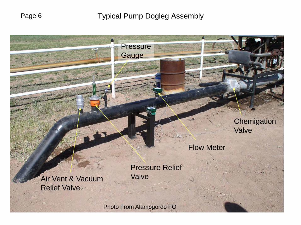
Typical Pump Dogleg AssemblyPage 6
ChemigationValve
Flow Meter
Air Vent & Vacuum Relief Valve
Pressure ReliefValve
PressureGauge
Photo From Alamogordo FO

IS-6
Page 7 Typical Gravity Discharge Assembly

IS-6
Plastic Irrigation Pipe MarkingsExample
Manufacturer’sName
Pipe Diameter
Pressure Rating
Pipe Description -i.e. Plastic IrrigationPipe (PIP)
NRCS PracticeDescription
MaterialDesignation
Page 8
Photo From Clayton FO

IS-6
Irrigation PipelineTee and Elbow
Coupler
Tee
Elbow
Page 9
Photo From Alamogordo FO

IS-6
Page 10 Typical Types Of Thrust Blocks

IS-6
MINIMUM DEPTH OF COVER
Pipe shall be installed at sufficient depth below the ground surface to provide protection from hazards imposed by traffic crossings, farming operations, freezing temperatures, or soil cracking. The minimum depth of cover for pipe susceptible to any of these hazards shall be:
Pipe Diameter (in.) Depth of Cover (in.)
½ through 2 ½ 18
3 through 5 24
6 or more 30
In areas where the pipe will not be susceptible to freezing and vehicular or cultivation hazards, and the soils do not crack appreciably when dry, the minimum depth of cover may be reduced to:
Pipe Diameter (in.) Depth of Cover (in.)
½ through 1 ½ 6
2 through 3 12
4 through 6 18
6 or more 24
Page 11

IS-6
Documentation of Depth of CoverPage 12
Photo from Estancia FO