iron& steel industry
TRANSCRIPT
5/16/2018 Iron& Steel Industry - slidepdf.com
http://slidepdf.com/reader/full/iron-steel-industry-55ab59521ea6d 1/50
IRON & ST EL INDUS
United Nations Industrial Development Organization
(UNIDO) and
Ministry of International Trade and Industry
(MITI), Japan
Hosted by
Ministry of Energy, Telecommu- Ministry of Mines andnications and Post, Malaysia Energy, Indonesia
Organized by
The Energy Conservation Center (ECC), Japan
Malaysia
1992
Indonesia
5/16/2018 Iron& Steel Industry - slidepdf.com
http://slidepdf.com/reader/full/iron-steel-industry-55ab59521ea6d 2/50
Preface
The conservation of energy is an essential step we can all take towards overcoming the
mounting problems of the worldwide energy crisis and environmental degradation. Inparticular, developing countries are interested to increase their awareness on the inefficient
power generation and energy usage in their countries. However, usually only limited
information sources on the rational use of energy are available.
The know-how on modern energy saving and conservation technologies should,
therefore, be disseminated to governments and industrial managers, as well as to engineers
and operators at the plant level in developing countries. It is particularly important that
they acquire practical knowledge of the currently available energy conservation
technologies and techniques.
In December 1983, UNIDO organized a Regional Meeting on Energy Consumption
as well as an Expert Group Meeting on Energy Conservation in small- and medium-scale
industries for Asian countries. During these meetings, it was brought out that, for some
energy intensive industries, savings up to 10% could be achieved through basic
housekeeping improvements, such as auditing and energy management.
The rational use of energy calls for a broad application of energy conservation
technologies in the various industrial sectors where energy is wasted. One of these energy
intensive industrial sectors to be considered to improve efficiency through the introduction
of modern energy conservation technologies is the steel industry.
In the steel industry, significant improvements in the level of energy efficiency could
be achieved by utilizing waste heat from furnaces, adjusting air/fuel ratio in furnace and
boiler burners and using drain water, as well as by eliminating and linking production
processes.
Currently, UNIDO, with the financial support of the Japanese Government, is
carrying out a Regional Programme on the promotion and application of energy saving
technologies in selected Asian developing countries. This programme aims at adopting
these innovative energy conservation technologies, developed in Japan, to the conditions of developing countries.
In this programme, we are considering that the transfer of these technologies could be
achieved through:
(i) Conducting surveys of energy usage and efficiency at the plant level;
(ii) Preparing manuals on energy management and energy conservation/saving
technologies, based on the findings of the above surveys;
5/16/2018 Iron& Steel Industry - slidepdf.com
http://slidepdf.com/reader/full/iron-steel-industry-55ab59521ea6d 3/50
(iii) Presenting and discussing the manuals at seminars held for government offtcials,
representatives of industries, plant managers and engineers;
(iv) Disseminating the manuals to other developing countries for their proper utilizationand application by the industrial sector.
The experience obtained through this programme will be applied to other
programmes/projects which involve other industrial sectors as well as other developing
countries and regions.
UNIDO has started this programme with the project US/RAS/90/075 - Rational Use
of Energy Resources in Steel and Textile Industry in Malaysia and Indonesia.
The present Handy Manual on Iron and Steel Industry was prepared by UNIDO, with
the cooperation of experts from the Energy Conservation Center (ECC) of Japan, onenergy saving technologies in the framework of the above mentioned UNIDO project. It
is based on the results of the surveys carried out, the plant observations and the
recommendations and suggestions emanating from the Seminars on Energy Conservation
in the Steel and Textile Industries, held under the same project in January 1992 in Jakarta,
Indonesia, and Kuala Lumpur, Malaysia. The manual will not only be interesting for
government and representatives from industry, but it is, in particular, designed for plant-
level engineers and operators in developing countries as a help to improve energy
efficiency in the production process.
Appreciation is expressed for the valuable contribution made by the following
institutions to the successful preparation and publication of the manual mentioned above:
Ministry of Mines and Energy, Indonesia
Ministry of Energy, Telecommunications and Posts, Malaysia
Ministry of International Trade and Industry (MITI), Japan
The Energy Conservation Center (ECC), Japan
June 1992
5/16/2018 Iron& Steel Industry - slidepdf.com
http://slidepdf.com/reader/full/iron-steel-industry-55ab59521ea6d 4/50
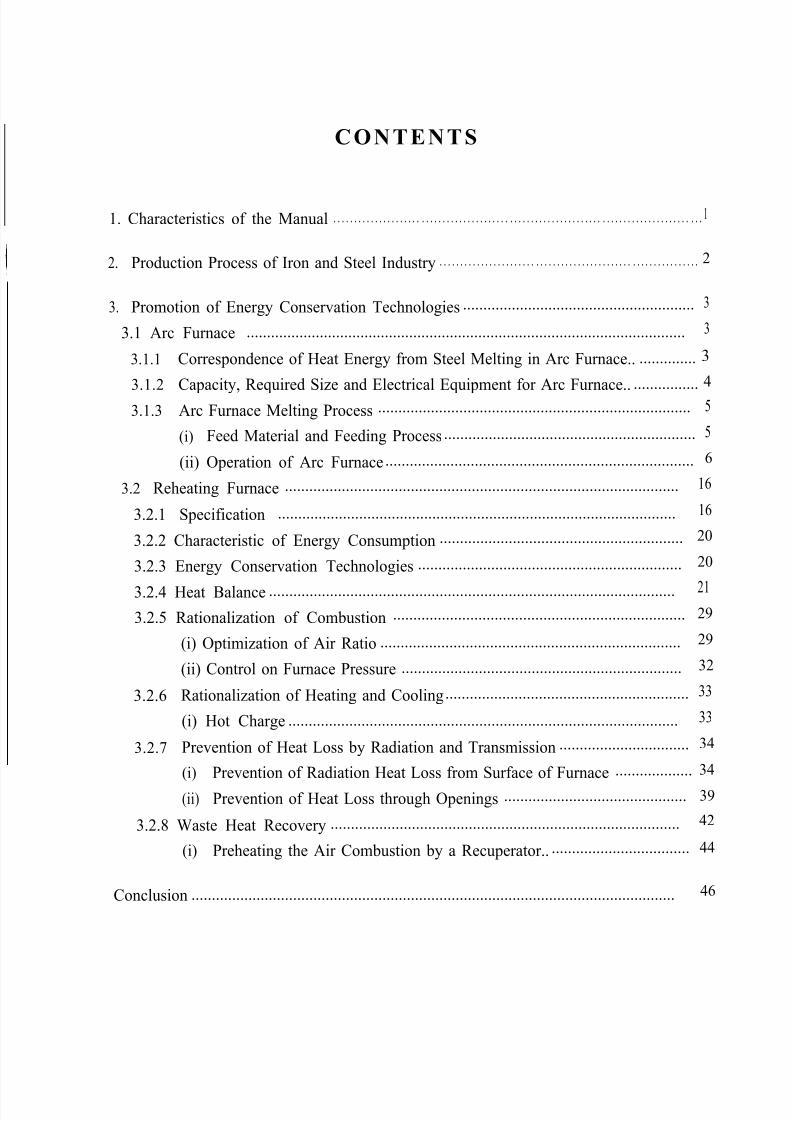
CONTENTS
1. Characteristics of the Manual . . . . . . . . . . . . . . . . . . . . . . . . . . . . . . . . . . . . . . . . . . . . . . . . . . . . . . . . . . . . . . . . . . . . . . . . . . . . . . . . . . . . . . . .1
2. Production Process of Iron and Steel Industry . . . . . . . . . . . . . . . . . . . . . . . . . . . . . . . . . . . . . . . . . . . . . . . . . . . . . . . . . . . . . . 2
3. Promotion of Energy Conservation Technologies ......................................................... 3
3.1 Arc Furnace ............................................................................................................ 3
3.1.1 Correspondence of Heat Energy from Steel Melting in Arc Furnace.. .............. 3
3.1.2 Capacity, Required Size and Electrical Equipment for Arc Furnace.. ................4
3.1.3 Arc Furnace Melting Process ............................................................................. 5
(i) Feed Material and Feeding Process .............................................................. 5
(ii) Operation of Arc Furnace ............................................................................ 6
3.2 Reheating Furnace ................................................................................................. 16
3.2.1 Specification .................................................................................................. 16
3.2.2 Characteristic of Energy Consumption ............................................................ 20
3.2.3 Energy Conservation Technologies ................................................................. 20
3.2.4 Heat Balance .................................................................................................... 21
3.2.5 Rationalization of Combustion ........................................................................ 29
(i) Optimization of Air Ratio .......................................................................... 29
(ii) Control on Furnace Pressure ..................................................................... 32
3.2.6 Rationalization of Heating and Cooling............................................................ 33
(i) Hot Charge ................................................................................................ 33
3.2.7 Prevention of Heat Loss by Radiation and Transmission ................................ 34
(i) Prevention of Radiation Heat Loss from Surface of Furnace ................... 34
(ii) Prevention of Heat Loss through Openings ............................................. 39
3.2.8 Waste Heat Recovery ...................................................................................... 42
(i) Preheating the Air Combustion by a Recuperator.. .................................. 44
Conclusion ....................................................................................................................... 46
5/16/2018 Iron& Steel Industry - slidepdf.com
http://slidepdf.com/reader/full/iron-steel-industry-55ab59521ea6d 5/50
1. Characteristics of the Manual
With the aim to promote energy conservation in the iron and steel industry, thismanual summarizes a number of measures which can be taken for an effective energy
conservation and describes how to apply them.
It focuses on arc furnaces and reheating furnaces, which consume a particularly large
amount of energy and for which further energy conservation measures have to be applied.
The manual describes general methods for energy conservation as well as practical
examples and results that can serve as reference for the engineers who deal with the
operation of mills. It will help them adopt suitable energy conservation measures for their
particular mills.
We hope that his manual will be used as a guide to better energy efficiency and to
more effective management practices in the iron and steel industry.
- l -
5/16/2018 Iron& Steel Industry - slidepdf.com
http://slidepdf.com/reader/full/iron-steel-industry-55ab59521ea6d 6/50
2. Production Process of Iron and Steel Industry
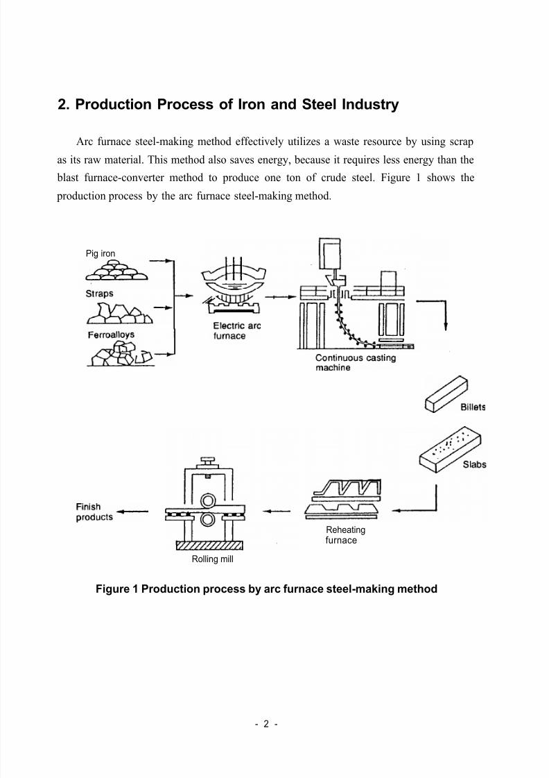
Arc furnace steel-making method effectively utilizes a waste resource by using scrap
as its raw material. This method also saves energy, because it requires less energy than the
blast furnace-converter method to produce one ton of crude steel. Figure 1 shows the
production process by the arc furnace steel-making method.
Pig iron
Reheating
furnaceRolling mill
Figure 1 Production process by arc furnace steel-making method
- 2 -
5/16/2018 Iron& Steel Industry - slidepdf.com
http://slidepdf.com/reader/full/iron-steel-industry-55ab59521ea6d 7/50
3. Promotion of Energy Conservation Technologies
3.1 Arc Furnace
3.1.1 Correspondence of Heat Energy from Steel melting in Arc Furnace
Electric power is the major source of heat energy used for arc furnaces.
In the steel industry, the arc furnace is mainly used to melt steel material by means of
the arc and electric resistance heating and remove undesirable components such as
phosphorus, sulfur, hydrogen and oxygen from the material through different chemical
reactions including decarburization, dephosphorization, desulfurization and deoxidation in
order to impart it with required physical and mechanical characteristics while adjusting the
contents of major components such as carbon so that steel with good properties can beobtained.
To achieve these objectives, it is essential to perform the whole process as quickly as
possible because the above reactions may proceed reversibly as the material stays under
the melting conditions in an arc furnace for a lengthy period of time.
Major methods currently used to accelerate the melting process and to save electric
power required for the process include the use of an oil burner for auxiliary melting of the
material in the furnace, use of a lance pipe to stop the supply of oxygen, blowing of
oxygen into the metal bath and, in some cases, use of a heavy weight to compress bulky
feed material in the furnace.
Energy-Saving Measures through the Operation of Arc Furnaces
In order to save energy one should:
(1) Reduce operating hours
(2) Raise the resistance welding time in order to eliminate wasteful power
consumption. Consequently, the use of excessively bulky materials should be
avoided as much as possible, and they should be pressed and massed together.
(3) Effectively use oxygen blow to quickly raise the temperature to over 1,600°C. The
use of essentials, such as a poker, is desirable.
(4) As a charge will come two or three times, it is necessary, in order to secure
operation speed, to have close contact between the crane operator and other related
operators so that there is no waiting for the crane.
(5) Install high-powered transformers and carry out rapid dissolution.
- 3 -
5/16/2018 Iron& Steel Industry - slidepdf.com
http://slidepdf.com/reader/full/iron-steel-industry-55ab59521ea6d 8/50
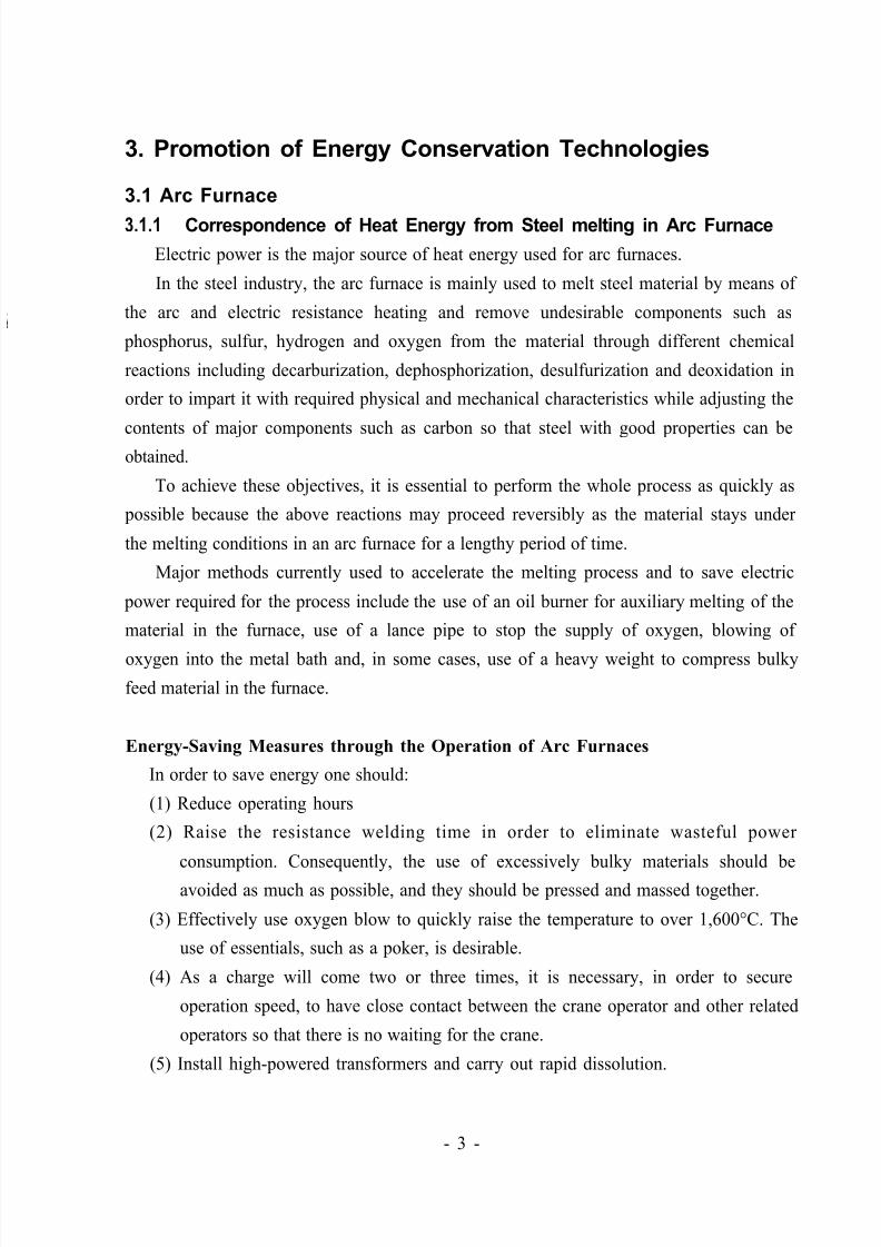
3.1.2 Capacity, Required Size and Electrical Equipment for Arc Furnace
Table 1 shows relations among capacity, required size and electrical equipment.
The melting rate depends largely on the capacity of the transformer as seen from
Table 2.
Table 1 Relations among furnace capacity, required size and electrical
equipment
Notes RP: regular power, HP: high power, UHP: ultra-high power
Source: Cast Product Handbook, 4th Ed., ed. Japan Cast Product Association
- 4 -
5/16/2018 Iron& Steel Industry - slidepdf.com
http://slidepdf.com/reader/full/iron-steel-industry-55ab59521ea6d 9/50
3.1.3 Arc Furnace Melting Process
(i) Feed Material and Feeding Process
a) Feed MaterialThe type of feed material used in the arc furnace melting process depends on the
product to be produced. Machine chips, pressed steel scraps, light steel scraps and
steel casting scraps are generally used for producing bars and sections, while steel
casting scraps, light steel scraps, machine chip scraps and steel casting scraps are
employed for producing steel castings.
In the former case, feed materials are bulky, and cannot be fed to the furnace in
one step, generally requiring three or more steps instead. In any case, it is
essential to prevent non-ferrous metals, including copper and aluminum, and non-
metallic substances, including rust and oil, from getting into the feed material.
b) Feeding of Material
Bulky feed materials are normally used for the production of general steel
products, as stated above. In general, the canopy is opened and a charging basket
is employed to feed them in several steps.
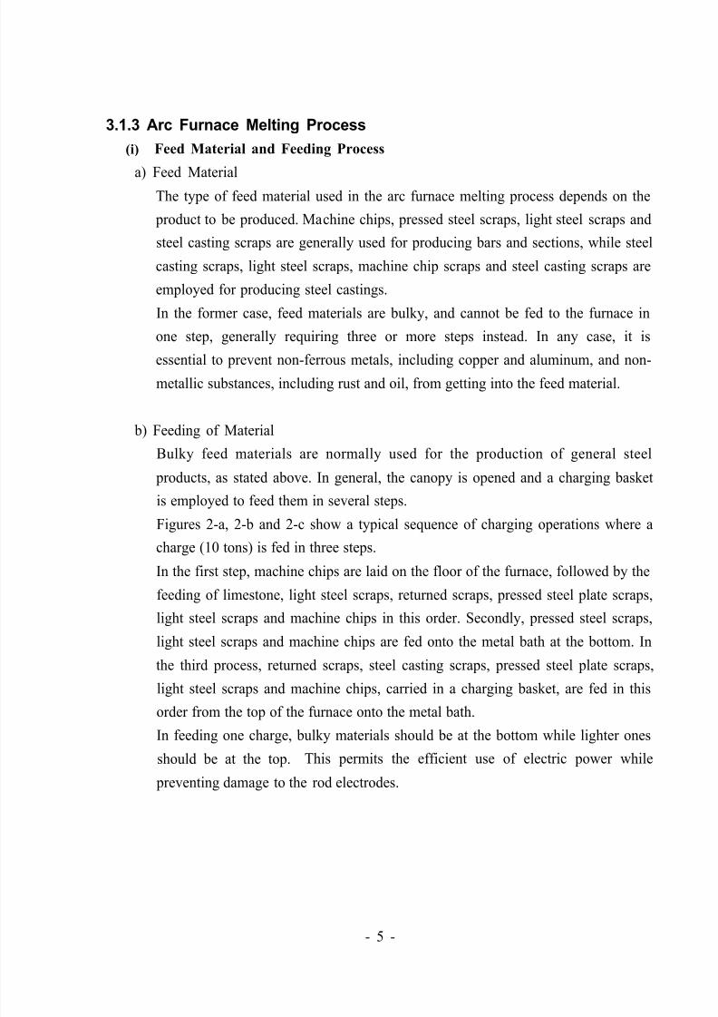
Figures 2-a, 2-b and 2-c show a typical sequence of charging operations where a
charge (10 tons) is fed in three steps.
In the first step, machine chips are laid on the floor of the furnace, followed by the
feeding of limestone, light steel scraps, returned scraps, pressed steel plate scraps,
light steel scraps and machine chips in this order. Secondly, pressed steel scraps,
light steel scraps and machine chips are fed onto the metal bath at the bottom. In
the third process, returned scraps, steel casting scraps, pressed steel plate scraps,
light steel scraps and machine chips, carried in a charging basket, are fed in this
order from the top of the furnace onto the metal bath.
In feeding one charge, bulky materials should be at the bottom while lighter ones
should be at the top. This permits the efficient use of electric power while
preventing damage to the rod electrodes.
- 5 -
5/16/2018 Iron& Steel Industry - slidepdf.com
http://slidepdf.com/reader/full/iron-steel-industry-55ab59521ea6d 10/50
2-b
Figure 2 Method and sequence of feeding material to arc furnace
(fed in three steps)
A bypass may be provided between the dust collector and the arc furnace, with a
charging basket placed there for pre-heating in waste gas. This can reduce the
power consumption by 20-50 kWh/t.
Operation of Arc Furnace
After charging the arc furnace with materials, electric power is supplied and then
melting operations are performed as described in the following example, where a
furnace with a capacity of eight tons (IO-ton charge) is used.
- 6 -
5/16/2018 Iron& Steel Industry - slidepdf.com
http://slidepdf.com/reader/full/iron-steel-industry-55ab59521ea6d 11/50
a) Melting Period
The melting period accounts for more than 50% of the total power consumption
used in the entire arc furnace melting process. The operations, therefore, requireskilled workers.
a. Blending of feed Material
The following material composition and charging sequence are recommended.
Desired composition
Light steel scraps: approx. 60%
Steel cutting scraps: 15%
Pressed steel scraps: 15%
Pressed steel plate scraps: 5%
Returned steel scraps: 5%
Where charging is performed in three steps, it is recommended to adjust their
weight ratio to 45%, 30% and 25%.
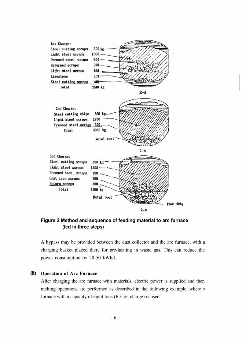
b. Oil Burner
For the saving of electric power, an oil burner is used to accelerate the melting of
the fed material. In this case, the burner is fixed at a cold spot in the furnace as
shown in Figure 3 so as to avoid the burning of the electrodes.
Source: Cast Product Handbook, 4th Ed., ed. Japan Cast Product Association
Figure 3 Swing side oil burner
- 7 -
5/16/2018 Iron& Steel Industry - slidepdf.com
http://slidepdf.com/reader/full/iron-steel-industry-55ab59521ea6d 12/50
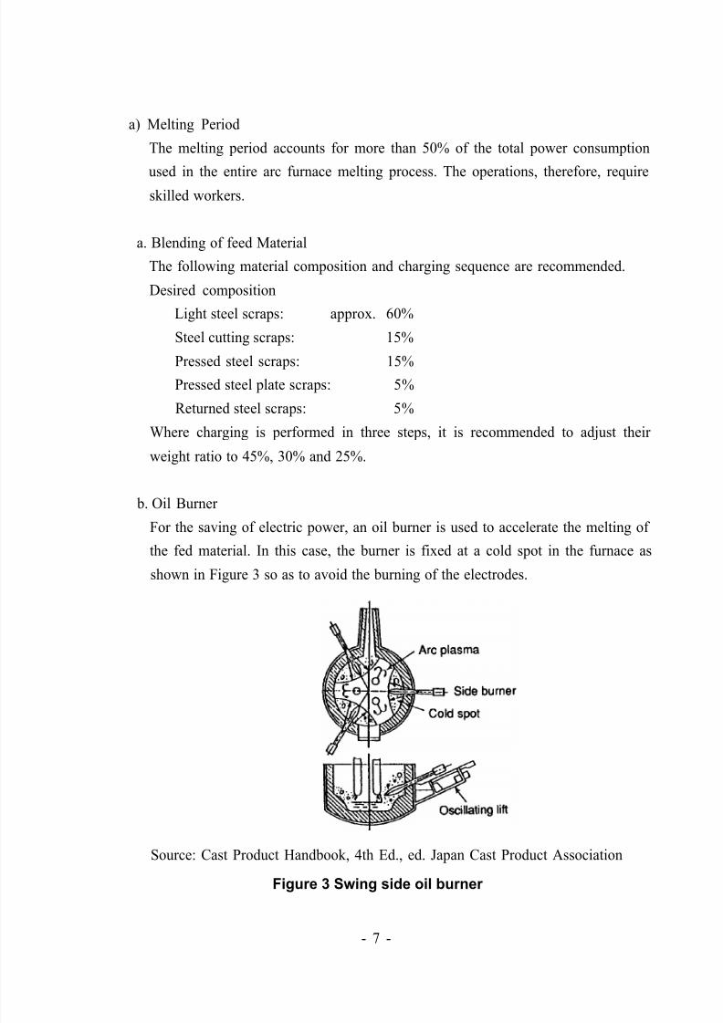
c. Specification and Use of Oxygen Lance Pipe
Oxygen lance cutting should be performed along the side wall of the furnace in a
way that will not cause damage to the wall (Figure 4).
Lance cutting, if required, should be conducted as early as possible. Thus, it
should be started in about 15 min after the first charging, about 5 min after the
second charging, and about 5 min after the third charging (time measured after the
start of electric power supply).
Figure 4 Cutting of oxygen lance
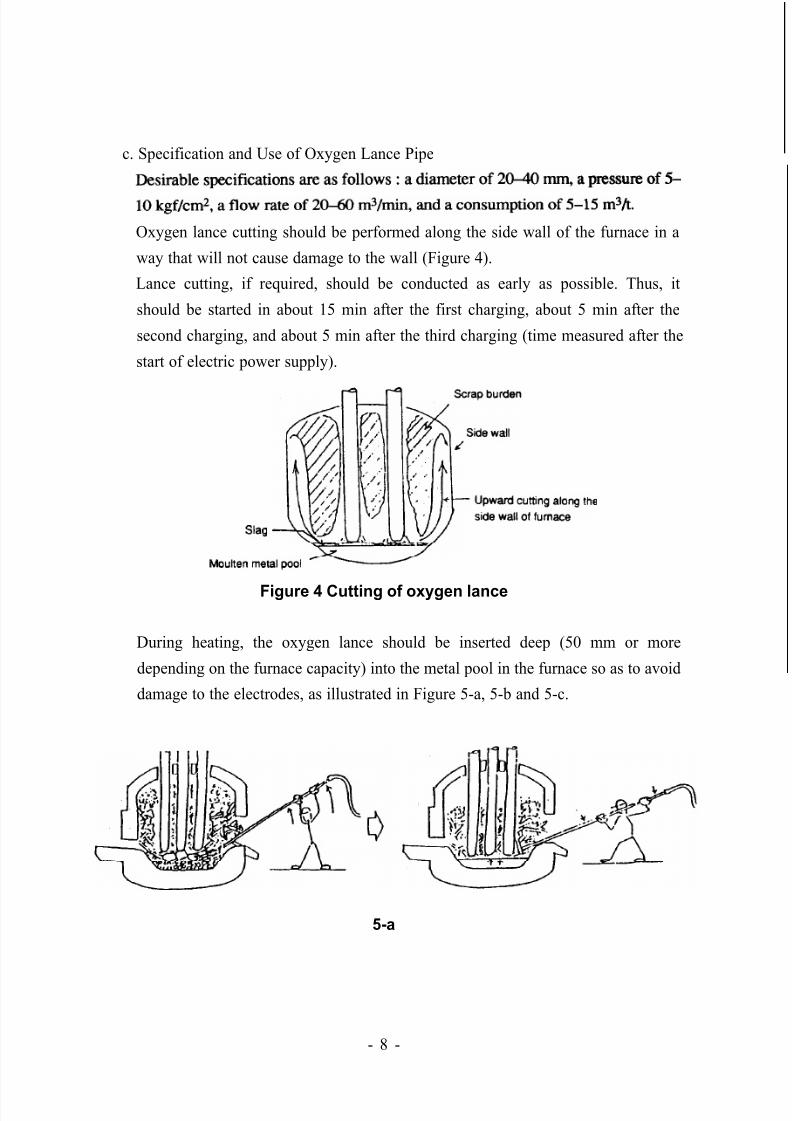
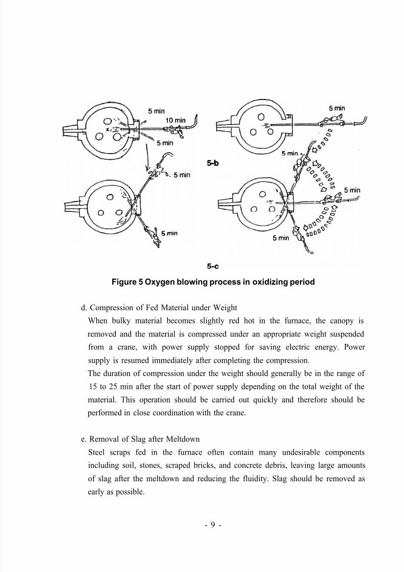
During heating, the oxygen lance should be inserted deep (50 mm or more
depending on the furnace capacity) into the metal pool in the furnace so as to avoid
damage to the electrodes, as illustrated in Figure 5-a, 5-b and 5-c.
5-a
- 8 -
5/16/2018 Iron& Steel Industry - slidepdf.com
http://slidepdf.com/reader/full/iron-steel-industry-55ab59521ea6d 13/50
Figure 5 Oxygen blowing process in oxidizing period
d. Compression of Fed Material under Weight
When bulky material becomes slightly red hot in the furnace, the canopy is
removed and the material is compressed under an appropriate weight suspended
from a crane, with power supply stopped for saving electric energy. Power
supply is resumed immediately after completing the compression.
The duration of compression under the weight should generally be in the range of
15 to 25 min after the start of power supply depending on the total weight of the
material. This operation should be carried out quickly and therefore should be
performed in close coordination with the crane.
e. Removal of Slag after Meltdown
Steel scraps fed in the furnace often contain many undesirable components
including soil, stones, scraped bricks, and concrete debris, leaving large amounts
of slag after the meltdown and reducing the fluidity. Slag should be removed as
early as possible.
- 9 -
5/16/2018 Iron& Steel Industry - slidepdf.com
http://slidepdf.com/reader/full/iron-steel-industry-55ab59521ea6d 14/50
b) Oxidizing Period
Samples are taken from the molten metal bath and subjected to analysis of the
contents of carbon, silicon, manganese and sulfur to allow composition adjustment
immediately before the start of the oxidizing period.
The oxidizing period is important in accelerating major processes including
dephosphorization, desulfurization, decarburization and deoxidation. This requires a
metal bath temperature of above 1,600°C. To achieve this, the voltage is decreased
to increase the current. Oxygen blowing through the lance pipe is performed during
this period. The description on temperature raise in Paragraph c. “Specification and
Use of Oxygen Lance Pipe” should be referred to for details of this operation. Themetal bath temperature should generally be above 1,620°C at the end of the
oxidizing period.
Slag in the surface of molten metal bath should be removed completely at the end of
the oxidizing period.
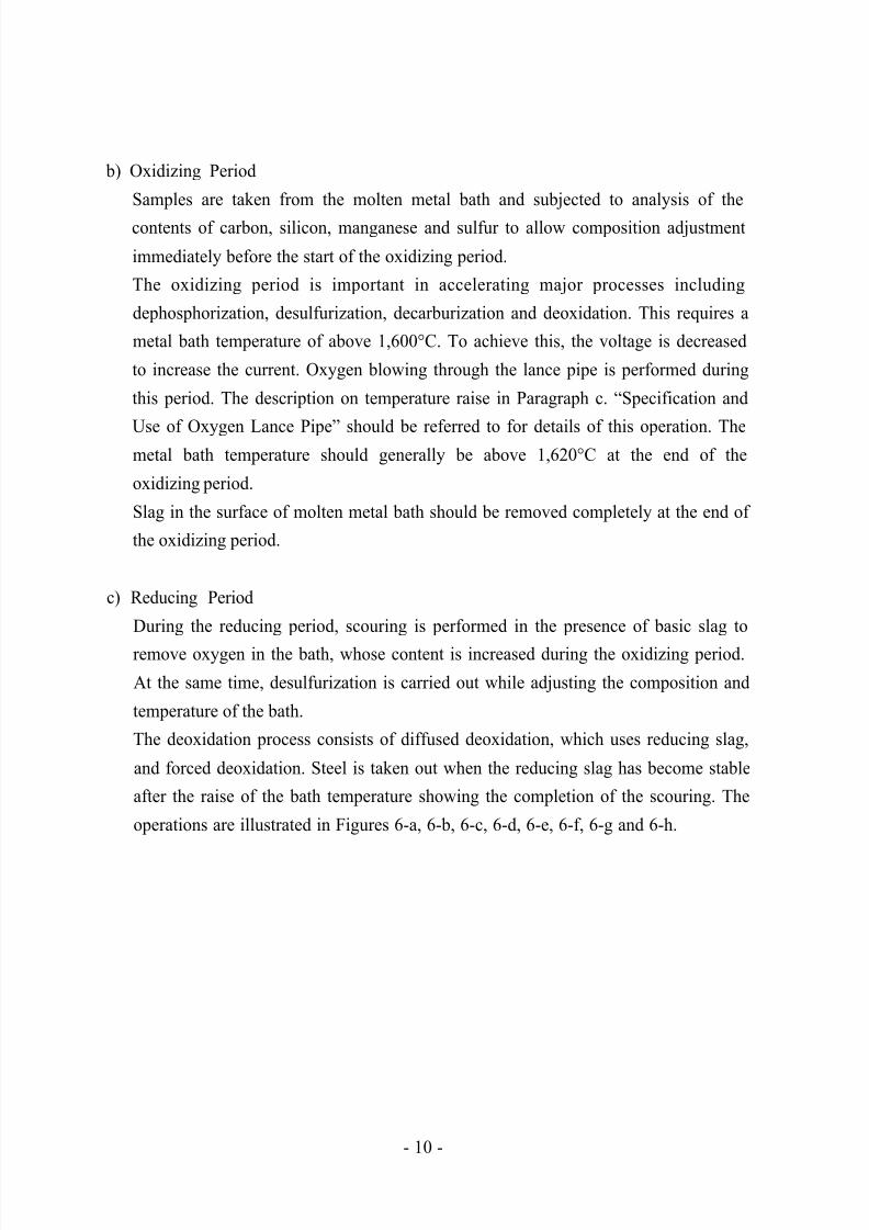
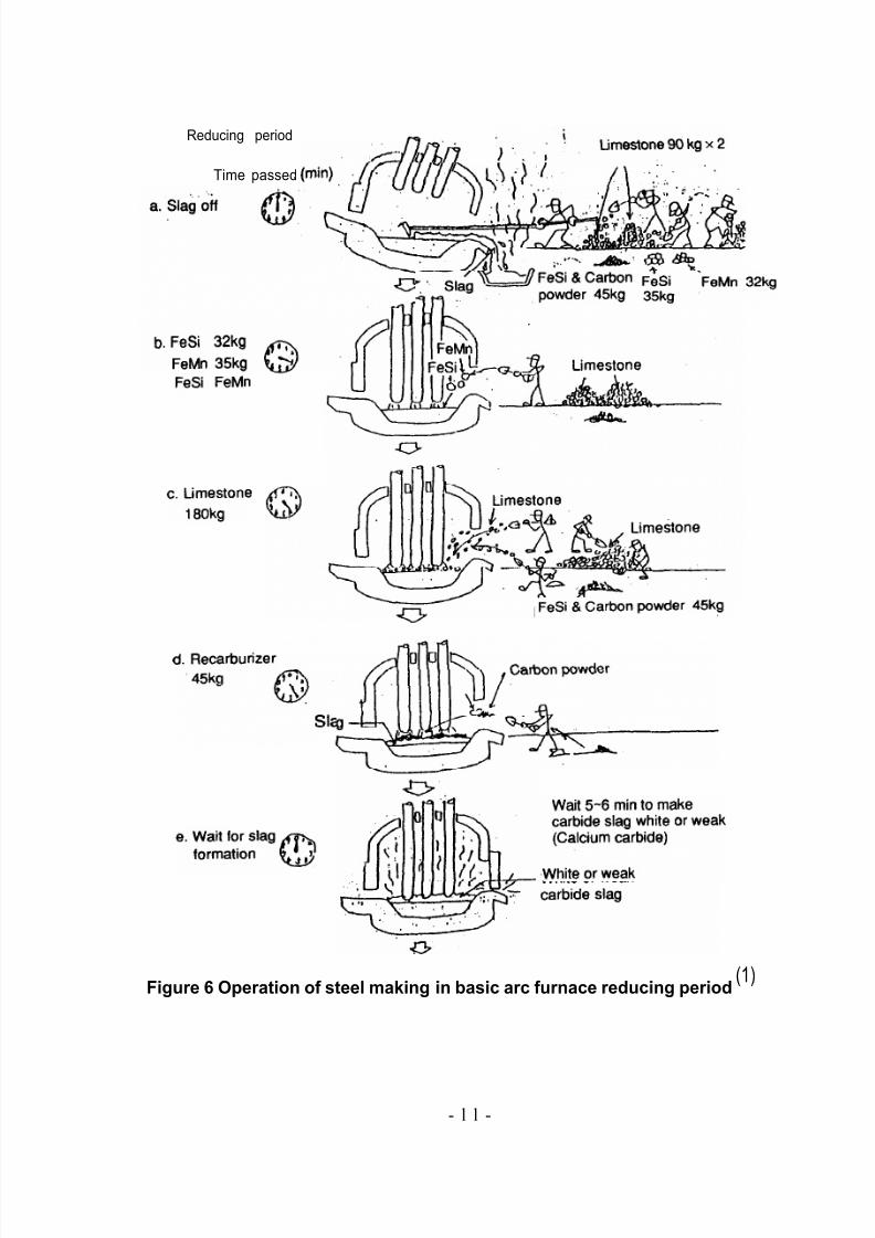
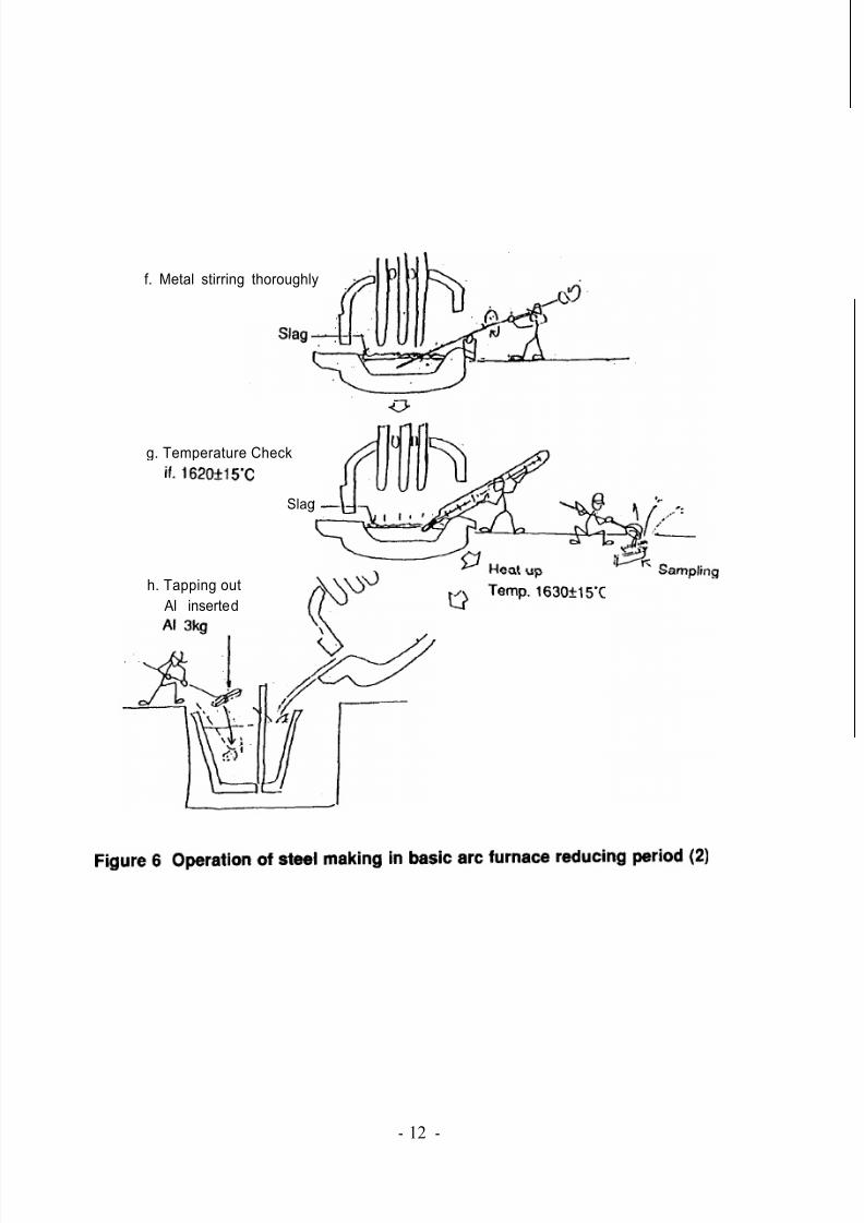
c) Reducing Period
During the reducing period, scouring is performed in the presence of basic slag to
remove oxygen in the bath, whose content is increased during the oxidizing period.
At the same time, desulfurization is carried out while adjusting the composition and
temperature of the bath.
The deoxidation process consists of diffused deoxidation, which uses reducing slag,
and forced deoxidation. Steel is taken out when the reducing slag has become stable
after the raise of the bath temperature showing the completion of the scouring. The
operations are illustrated in Figures 6-a, 6-b, 6-c, 6-d, 6-e, 6-f, 6-g and 6-h.
- 10 -
5/16/2018 Iron& Steel Industry - slidepdf.com
http://slidepdf.com/reader/full/iron-steel-industry-55ab59521ea6d 15/50
Reducing period
Time passed
Figure 6 Operation of steel making in basic arc furnace reducing period(1)
- l l -
5/16/2018 Iron& Steel Industry - slidepdf.com
http://slidepdf.com/reader/full/iron-steel-industry-55ab59521ea6d 16/50
f. Metal stirring thoroughly
g. Temperature Check
Slag
h. Tapping out
Al inserted
- 12 -
5/16/2018 Iron& Steel Industry - slidepdf.com
http://slidepdf.com/reader/full/iron-steel-industry-55ab59521ea6d 17/50
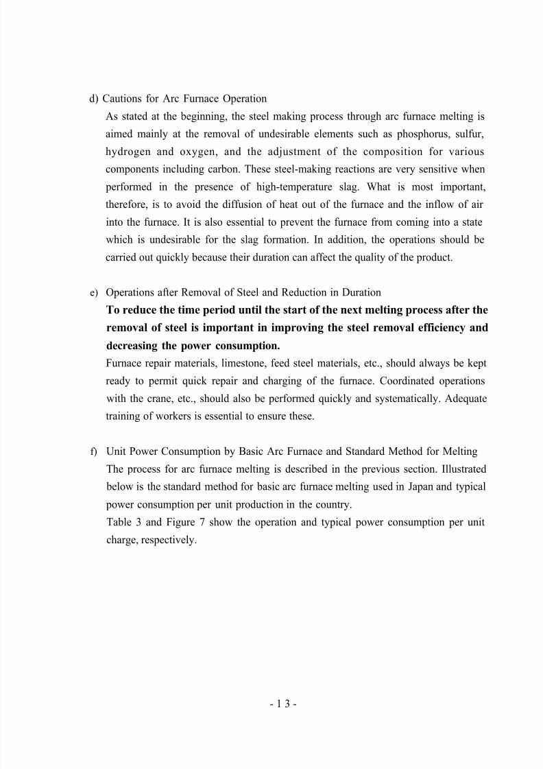
d) Cautions for Arc Furnace Operation
As stated at the beginning, the steel making process through arc furnace melting is
aimed mainly at the removal of undesirable elements such as phosphorus, sulfur,
hydrogen and oxygen, and the adjustment of the composition for various
components including carbon. These steel-making reactions are very sensitive when
performed in the presence of high-temperature slag. What is most important,
therefore, is to avoid the diffusion of heat out of the furnace and the inflow of air
into the furnace. It is also essential to prevent the furnace from coming into a state
which is undesirable for the slag formation. In addition, the operations should be
carried out quickly because their duration can affect the quality of the product.
e) Operations after Removal of Steel and Reduction in Duration
To reduce the time period until the start of the next melting process after the
removal of steel is important in improving the steel removal efficiency and
decreasing the power consumption.
Furnace repair materials, limestone, feed steel materials, etc., should always be kept
ready to permit quick repair and charging of the furnace. Coordinated operations
with the crane, etc., should also be performed quickly and systematically. Adequatetraining of workers is essential to ensure these.
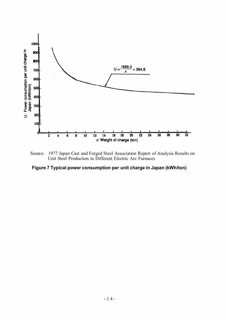
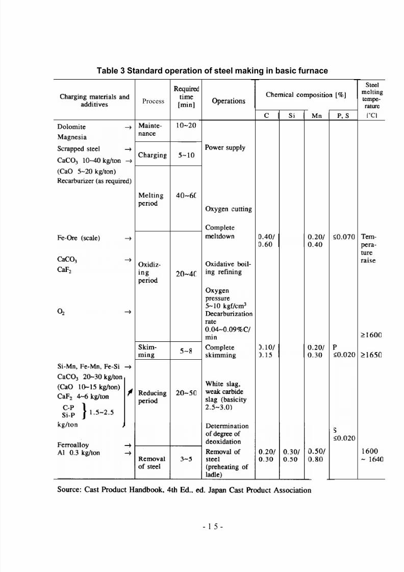
f) Unit Power Consumption by Basic Arc Furnace and Standard Method for Melting
The process for arc furnace melting is described in the previous section. Illustrated
below is the standard method for basic arc furnace melting used in Japan and typical
power consumption per unit production in the country.
Table 3 and Figure 7 show the operation and typical power consumption per unit
charge, respectively.
- 1 3 -
5/16/2018 Iron& Steel Industry - slidepdf.com
http://slidepdf.com/reader/full/iron-steel-industry-55ab59521ea6d 18/50
Source: 1977 Japan Cast and Forged Steel Association Report of Analysis Results onUnit Steel Production in Different Electric Arc Furnaces
Figure 7 Typical power consumption per unit charge in Japan (kWh/ton)
- 1 4 -
5/16/2018 Iron& Steel Industry - slidepdf.com
http://slidepdf.com/reader/full/iron-steel-industry-55ab59521ea6d 19/50
Table 3 Standard operation of steel making in basic furnace
Process
- 1 5 -
5/16/2018 Iron& Steel Industry - slidepdf.com
http://slidepdf.com/reader/full/iron-steel-industry-55ab59521ea6d 20/50
3.2 Reheating Furnace
3.2.1 Specification
After billets are roughly rolled at a blooming mill or made by continuous casting, a
reheating furnace reheats them at a given temperature according to its purpose before they
are sent to the hot rolling process to make finished products.
Reheating furnaces can be divided into batch-type furnaces and continuous furnaces.
Batch-type furnaces are mainly used as auxiliary equipment to reheat something of a
special form. For mass production, continuous furnaces are used in general.
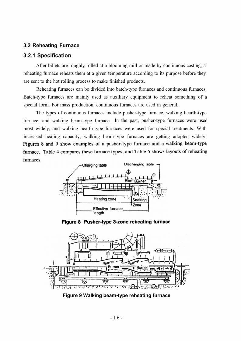
The types of continuous furnaces include pusher-type furnace, walking hearth-type
furnace, and walking beam-type furnace. In the past, pusher-type furnaces were used
most widely, and walking hearth-type furnaces were used for special treatments. With
increased heating capacity, walking beam-type furnaces are getting adopted widely.
Figure 9 Walking beam-type reheating furnace
- 1 6 -
5/16/2018 Iron& Steel Industry - slidepdf.com
http://slidepdf.com/reader/full/iron-steel-industry-55ab59521ea6d 21/50
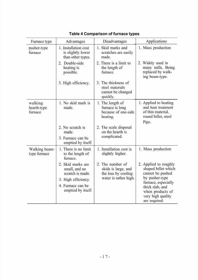
Table 4 Comparison of furnace types
Furnace type
pusher-typefurnace
walkinghearth-typefurnace
Walking beam-type furnace
Advantages
1. Installation costis slightly lowerthan other types.
2. Double-sideheating ispossible.
3. High efficiency.
1. No skid mark ismade.
2. No scratch ismade.
3. Furnace can beemptied by itself.
1. There is no limitto the length of furnace.
2. Skid marks aresmall, and noscratch is made.
3. High efficiency.
4. Furnace can beemptied by itself.
Disadvantages
1. Skid marks andscratches are easilymade.
2. There is a limit tothe length of furnace.
3. The thickness of steel materialscannot be changed
quickly.1. The length of
furnace is longbecause of one-sideheating.
2. The scale disposalon the hearth iscomplicated.
1. Installation cost isslightly higher.
2. The number of skids is large, andthe loss by coolingwater is rather high.
Applications
1. Mass production
2. Widely used inmany mills. Beingreplaced by walk-ing beam-type.
1. Applied to heatingand heat treatmentof thin material,round billet, steel
Pipe.
1. Mass production
2. Applied to roughlyshaped billet whichcannot be pushedby pusher-typefurnace, especiallythick slab, andwhen products of
very high qualityare required.
- 1 7 -
5/16/2018 Iron& Steel Industry - slidepdf.com
http://slidepdf.com/reader/full/iron-steel-industry-55ab59521ea6d 22/50
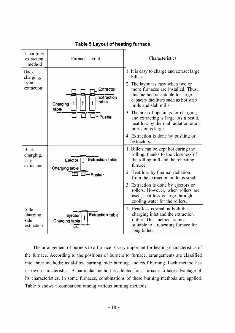
Table 5 Layout of heating furnace
Charging/
extractionmethod
Back charging,
frontextraction
Back charging,sideextraction
Sidecharging,sideextraction
Furnace layout Characteristics
1. It is easy to charge and extract largebillets.
2. The layout is easy when two ormore furnaces are installed. Thus,this method is suitable for large-capacity facilities such as hot stripmills and slab mills.
3. The area of openings for chargingand extracting is large. As a result,heat loss by thermal radiation or airintrusion is large.
4. Extraction is done by pushing orextractors.
1. Billets can be kept hot during therolling, thanks to the closeness of the rolling mill and the reheatingfurnace.
2. Heat loss by thermal radiationfrom the extraction outlet is small.
3. Extraction is done by ejectors orrollers. However, when rollers areused, heat loss is large throughcooling water for the rollers.
1. Heat loss is small at both thecharging inlet and the extractionoutlet. This method is mostsuitable to a reheating furnace for
long billets.
The arrangement of burners to a furnace is very important for heating characteristics of
the furnace. According to the positions of burners to furnace, arrangements are classified
into three methods; axial-flow burning, side burning, and roof burning. Each method has
its own characteristics. A particular method is adopted for a furnace to take advantage of
its characteristics. In some furnaces, combinations of these burning methods are applied.
Table 6 shows a comparison among various burning methods.
- 18 -
5/16/2018 Iron& Steel Industry - slidepdf.com
http://slidepdf.com/reader/full/iron-steel-industry-55ab59521ea6d 23/50
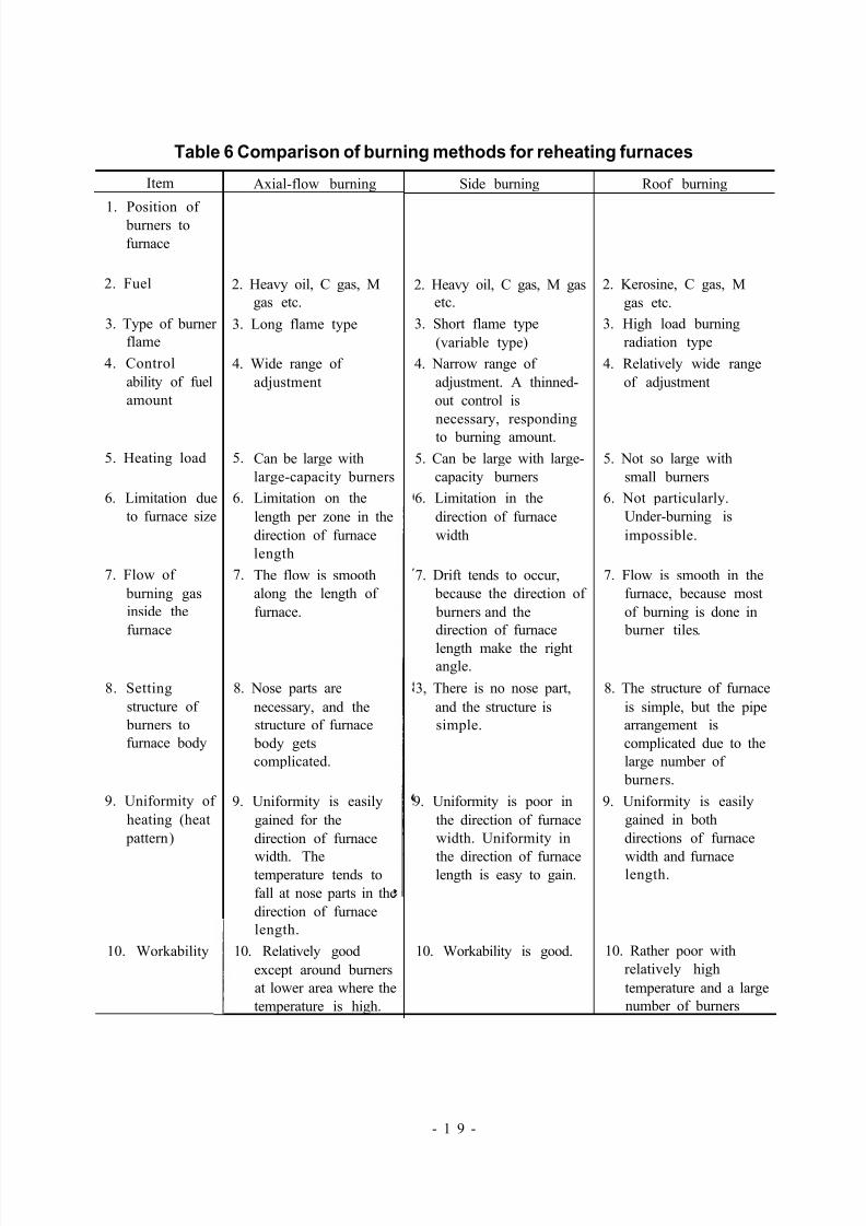
Table 6 Comparison of burning methods for reheating furnaces
Item
1. Position of burners to
furnace
2. Fuel
3. Type of burner
flame
4. Control
ability of fuel
amount
5. Heating load
6. Limitation due
to furnace size
7. Flow of
burning gas
inside the
furnace
8. Setting
structure of
burners to
furnace body
9. Uniformity of
heating (heat
pattern)
10. Workability
Axial-flow burning
2. Heavy oil, C gas, M
gas etc.
3. Long flame type
4. Wide range of
adjustment
5.
6.
7.
Can be large with
large-capacity burners
Limitation on the
length per zone in the
direction of furnace
length
The flow is smooth
along the length of
furnace.
8. Nose parts are
necessary, and the
structure of furnace
body gets
complicated.
9. Uniformity is easily
gained for the
direction of furnace
width. Thetemperature tends to
fall at nose parts in the
direction of furnace
length.
10. Relatively good
except around burners
at lower area where the
temperature is high.
Side burning
2. Heavy oil, C gas, M gas
etc.
3. Short flame type
(variable type)
4. Narrow range of
adjustment. A thinned-
out control is
necessary, responding
to burning amount.
5. Can be large with large-
capacity burners
6. Limitation in the
direction of furnace
width
7. Drift tends to occur,
because the direction of
burners and the
direction of furnace
length make the right
angle.
3, There is no nose part,
and the structure is
simple.
9. Uniformity is poor in
the direction of furnace
width. Uniformity in
the direction of furnacelength is easy to gain.
10. Workability is good.
Roof burning
2. Kerosine, C gas, M
gas etc.
3. High load burning
radiation type
4. Relatively wide range
of adjustment
5. Not so large with
small burners
6. Not particularly.
Under-burning is
impossible.
7. Flow is smooth in the
furnace, because most
of burning is done in
burner tiles.
8. The structure of furnace
is simple, but the pipe
arrangement is
complicated due to the
large number of
burners.
9. Uniformity is easily
gained in both
directions of furnace
width and furnacelength.
10. Rather poor with
relatively high
temperature and a large
number of burners
- 1 9 -
5/16/2018 Iron& Steel Industry - slidepdf.com
http://slidepdf.com/reader/full/iron-steel-industry-55ab59521ea6d 24/50
3.2.2 Characteristics of Energy Consumption
furnace, for which cooling water loss was large through water cooled beams. Today
walking beam-type furnaces are the majority rather than pusher-type furnaces, and their
result of the accumulation of measures which are described later. The dissemination of hot
charging, which utilizes a high temperature of the previous process, has also made a great
contribution to this improvement.
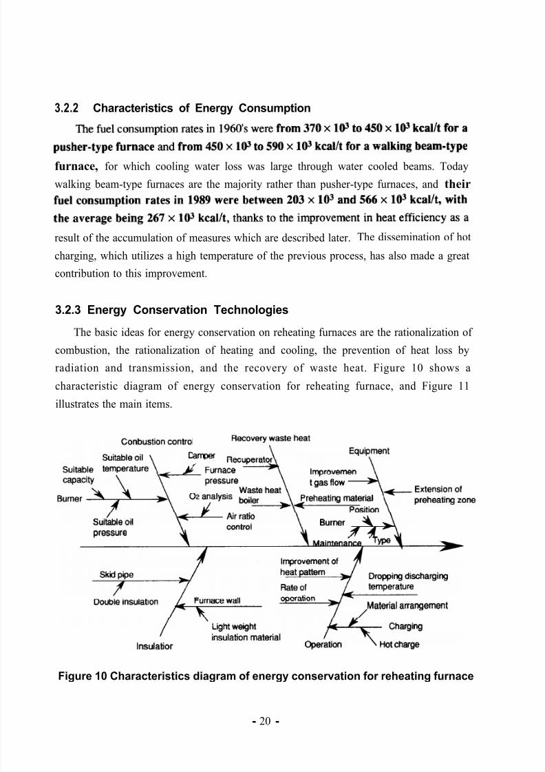
3.2.3 Energy Conservation Technologies
The basic ideas for energy conservation on reheating furnaces are the rationalization of
combustion, the rationalization of heating and cooling, the prevention of heat loss by
radiation and transmission, and the recovery of waste heat. Figure 10 shows a
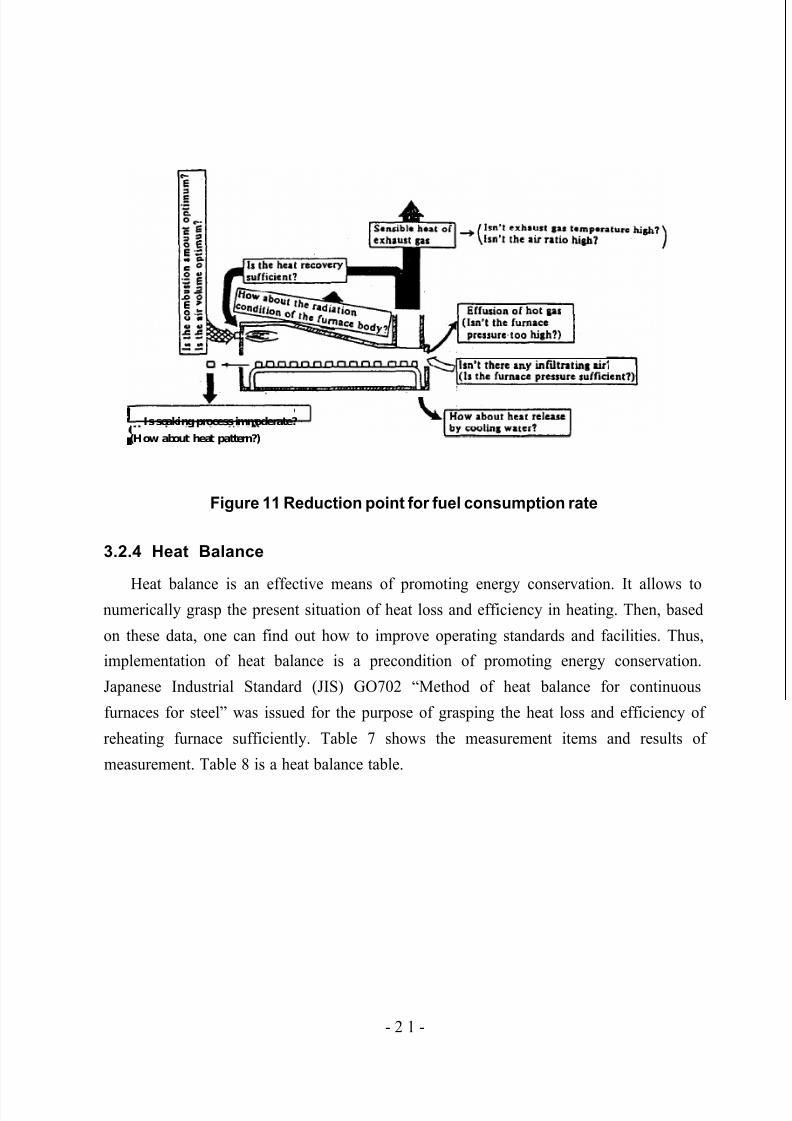
characteristic diagram of energy conservation for reheating furnace, and Figure 11
illustrates the main items.
Figure 10 Characteristics diagram of energy conservation for reheating furnace
- 20 -
5/16/2018 Iron& Steel Industry - slidepdf.com
http://slidepdf.com/reader/full/iron-steel-industry-55ab59521ea6d 25/50
Is soaking process immoderate?
(How about heat pattern?)
Figure 11 Reduction point for fuel consumption rate
3.2.4 Heat Balance
Heat balance is an effective means of promoting energy conservation. It allows tonumerically grasp the present situation of heat loss and efficiency in heating. Then, based
on these data, one can find out how to improve operating standards and facilities. Thus,
implementation of heat balance is a precondition of promoting energy conservation.
Japanese Industrial Standard (JIS) GO702 “Method of heat balance for continuous
furnaces for steel” was issued for the purpose of grasping the heat loss and efficiency of
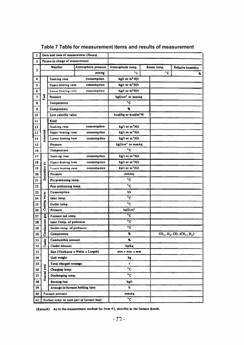
reheating furnace sufficiently. Table 7 shows the measurement items and results of
measurement. Table 8 is a heat balance table.
- 2 1 -
5/16/2018 Iron& Steel Industry - slidepdf.com
http://slidepdf.com/reader/full/iron-steel-industry-55ab59521ea6d 26/50
Table 7 Table for measurement items and results of measurement
- 2 2 -

5/16/2018 Iron& Steel Industry - slidepdf.com
http://slidepdf.com/reader/full/iron-steel-industry-55ab59521ea6d 27/50
Table 8 Heat balance table
Heat input Heat output
Item Item
(1) Combustion heat of (8) Quantity of heatfuel contained by extracted
steel
(2) Sensible heat of fuel (9) Sensible heat of scale
(3) Sensible heat of air (10) Sensible heat of exhaust gas
(4) Heat brought in by (11) Heat loss by
atomizer incomplete burning(5) Quantity of heat (12) Quantity of heat
contained by brought out by coolingcharged steel water
(6) Heat of scale (13) Quantity of heatformation brought out by cooling
water
(7) Heat recovered bypreheater
Total
(1) + (2) + (3) + (4)+ (5) + (6)
( ) ( )
(14) Other heat loss(15) Heat recovered by ( ) ( )
preheater
Total(8) + (9) + (10) + (ll)+ (12)
+ (13) + (14)
Remark 1. For recording the quantity of heat, use 103kcal/t as a unit and round our figures
after the decimal point into a single digit.
2. Round out figures after the decimal point into a single digit in the percentage.
The following is a concrete example of heat balance on a continuous steel reheating
furnace.
(1) Standard for heat balance
Heat balance is measured for one ton of charging steel with the outside air
temperature and the low calorific value of fuel at operation as its standard.
- 23 -
5/16/2018 Iron& Steel Industry - slidepdf.com
http://slidepdf.com/reader/full/iron-steel-industry-55ab59521ea6d 28/50
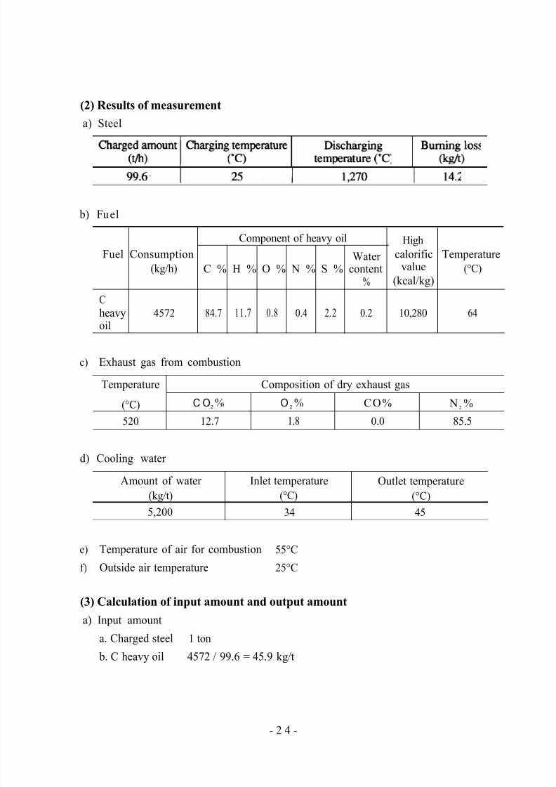
(2) Results of measurement
a) Steel
b) Fuel
Component of heavy oil High
Fuel Consumption Water calorific Temperature
(kg/h)C % H % O % N % S % content
value (°C)
% (kcal/kg)
C
heavy 4572 84.7 11.7 0.8 0.4 2.2 0.2 10,280 64
oil
c) Exhaust gas from combustion
Temperature
(°C)
520
C O2 %
12.7
Composition of dry exhaust gas
O 2 % CO%
1.8 0.0
N 2 %
85.5
d) Cooling water
Amount of water Inlet temperature
(kg/t) (°C)
5,200 34
Outlet temperature
(°C)
45
e) Temperature of air for combustion 55°C
f) Outside air temperature 25°C
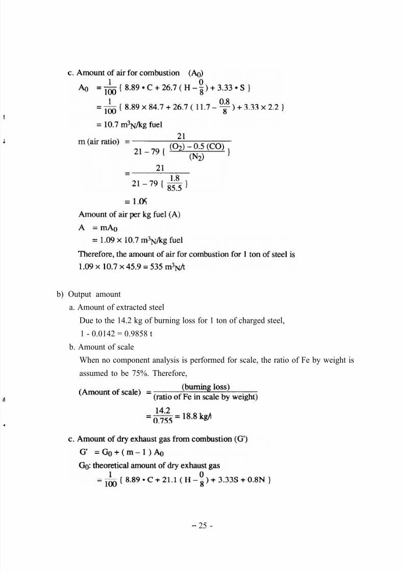
(3) Calculation of input amount and output amount
a) Input amount
a. Charged steel 1 ton
b. C heavy oil 4572 / 99.6 = 45.9 kg/t
- 2 4 -
5/16/2018 Iron& Steel Industry - slidepdf.com
http://slidepdf.com/reader/full/iron-steel-industry-55ab59521ea6d 29/50
b) Output amount
a. Amount of extracted steel
Due to the 14.2 kg of burning loss for 1 ton of charged steel,
1 - 0.0142 = 0.9858 t
b. Amount of scale
When no component analysis is performed for scale, the ratio of Fe by weight is
assumed to be 75%. Therefore,
- 25 -
5/16/2018 Iron& Steel Industry - slidepdf.com
http://slidepdf.com/reader/full/iron-steel-industry-55ab59521ea6d 30/50
(4) Calculation of heat input and heat output
a) Heat input
a. Low calorific value of fuel (Hl)
Hl = Hh - 600( 9H + water content )
Hh: high calorific value
= 1 0 2 8 0 - 6 0 0 ( 9 x 0 . 1 1 7 + 0 . 0 0 2 )
= 9650 kcal/kg fuel
For 1 ton of steel,
9650 x 45.9 = 442940 kcal/t
b. Sensible heat of fuel
45.9 x 0.45 x ( 64 - 25 ) = 810 kcal/t
c. Sensible heat of air
( 535 x 0.31 ) x ( 55 - 25 ) = 4980 kcal/t
d. Contained quantity of heat in charged steel
Since steel is charged at outside air temperature, its contained quantity of heat is
zero.
e. Heat of formation of scale
- 2 6 -
5/16/2018 Iron& Steel Industry - slidepdf.com
http://slidepdf.com/reader/full/iron-steel-industry-55ab59521ea6d 31/50
When no component analysis is performed for scale, heat of formation of scale
is assumed to be 1335 kcal/kg*Fe for 1 kg of Fe contained in the scale.
Therefore, 1335 x 14.2 = 18960 kcal/t
b) Heat output
a. Contained quantity of heat of extracted steel
[ 1 ,OOfl (kg) - burning loss of Fe (kg)] x [contained quantity of heat of steel at
discharging temperature (kcal/kg) - contained quantity of heat of steel at outside
air temperature (kcal/kg)]
= ( 1000 - 14.2 ) x { (200.4 - ( - 2.9 ) ) = 200410 kcal/t
b. Sensible heat of scale
0.215 kcal/kg*“C is used for the mean specific heat of scale. It is assumed that
the temperature of scale when it comes out from the furnace is same as the
discharging temperature of steel.
18.8 x 0.215 x ( 1270 - 25 ) = 5030 kcal/t
c. Sensible heat of dry exhaust gas from combustion
Assuming that the mean specific heat of dry exhaust gas from combustion is
0.33 kCal/IT13N*oC,
509.5 x 0.33 x ( 520 - 25 ) = 83230 kcal/t
d. Heat held in water vapor in exhaust gas
Assuming that the mean specific heat of water vapor is 0.45 kcal/kg*“C,
48.7 x 0.45 x ( 520 - 25 ) = 10850 kcal/t
e. Heat taken away by cooling water
Assuming that the mean specific heat of water is 1 kcal/kg*“C,
5200x 1 x(45-34)=572OOkcal/t
f. Other heat loss
The difference between the total heat input and the total heat output.
(442940+ 810+4980+ 18960)-c 200410+5030+ 83230+ 10850+57200)
= 110970 kcal
Table 9 shows the heat balance which summarizes the results above.
- 27 -
5/16/2018 Iron& Steel Industry - slidepdf.com
http://slidepdf.com/reader/full/iron-steel-industry-55ab59521ea6d 32/50
Table 9 Heat balance table
Heat input Heat output
lo3 %kcavt I I Item 103
kcavt%Item
(1) Combustion. heat of fuel
200.4 42.8442.9 94.7 (8) Quantity of heatcontained by extractedsteel
0.8 0.2 (9) Sensible heat of scale
5.0 1.1 (10) Sensible heat of exhaust gas
0 0 (11) Heat loss byincomplete burning
0 0 (12) Quantity of heat
brought out by coolingwater
19.0 4.0 (13) Quantity of heatbrought out by coolingwater
(2) Sensible heat of fuel 5.0 1.1
(3) Sensible heat of air 94.1 20.1
(4) Heat brought in byatomizer
0 0
0(5) Quantity of heatcontained bycharged steel
(6) Heat of scaleformation
0
12.257.2
(7) Heat recovered bypreheater
(0) I I0)
111.0 23.8(14) Other heat loss
(15) Heat recovered bypreheater
467.7 100.0 Total(8) + (9) + (10) + (ll)+ (12)
+ (13) + (14)
(0) (0)
Total
(1) + (2) + (3) + (4)+ (5) + (6)
467.7 100.0
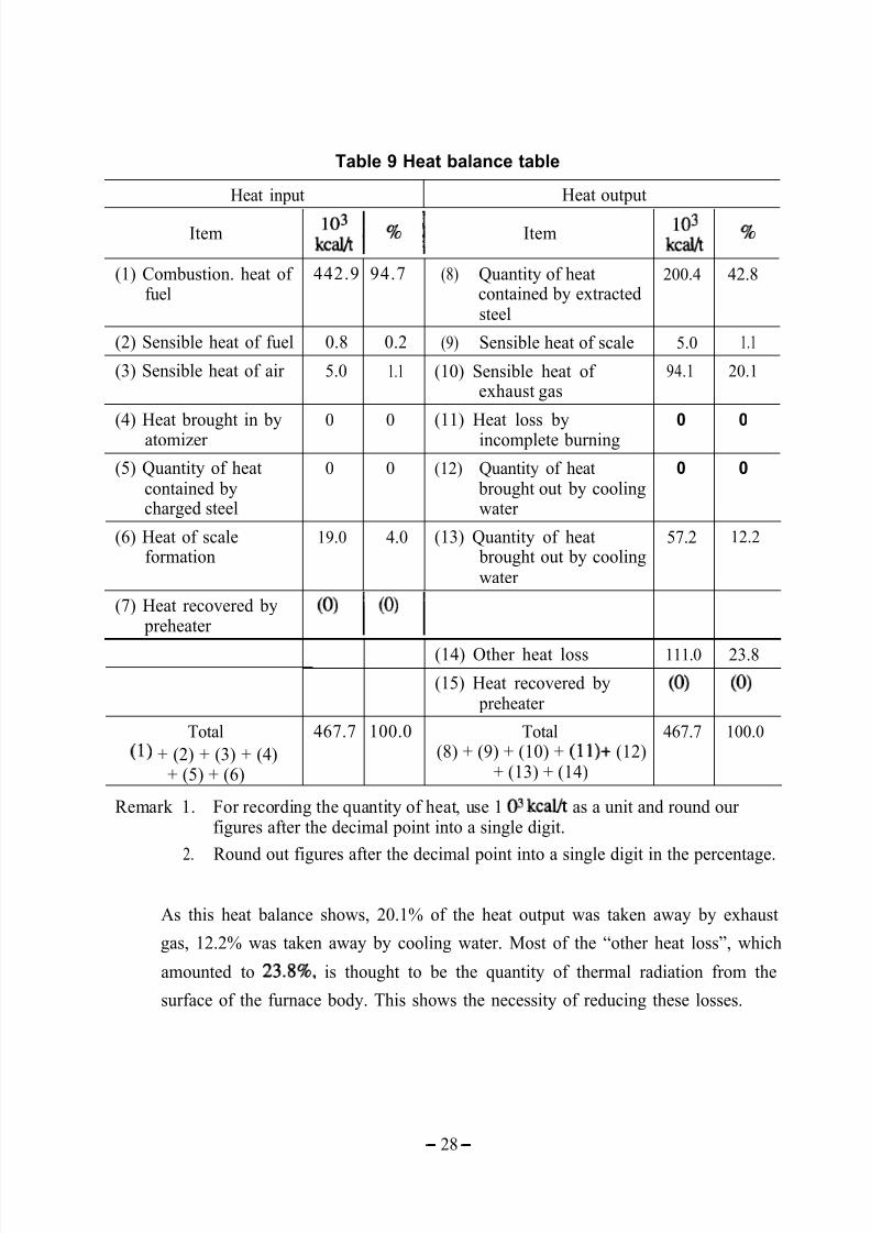
Remark 1. For recording the quantity of heat, use 1 O3 kcal/t as a unit and round ourfigures after the decimal point into a single digit.
2. Round out figures after the decimal point into a single digit in the percentage.
As this heat balance shows, 20.1% of the heat output was taken away by exhaust
gas, 12.2% was taken away by cooling water. Most of the “other heat loss”, which
amounted to 23.8%, is thought to be the quantity of thermal radiation from the
surface of the furnace body. This shows the necessity of reducing these losses.
- 28 -
5/16/2018 Iron& Steel Industry - slidepdf.com
http://slidepdf.com/reader/full/iron-steel-industry-55ab59521ea6d 33/50
3.2.5 Rationalization of Combustion
(i) Optimization of Air Ratio
As for a reheating furnace, the optimization of air ratio is the handiest and mosteconomical measure for energy conservation. The effect of this measure is higher
when the temperature of furnace is high. Air ratio is the value that is given by
dividing the consumed air amount by the theoretical combustion air amount, and it
represents the extent of excess of air. In Japan, the standard air ratio for a
continuous steel reheating furnace is set at 1.25. And this value of standard air ratio
is stipulated as the air ratio measured at the outlet of furnace during the combustion
around the rated load after checking and repairing are done.
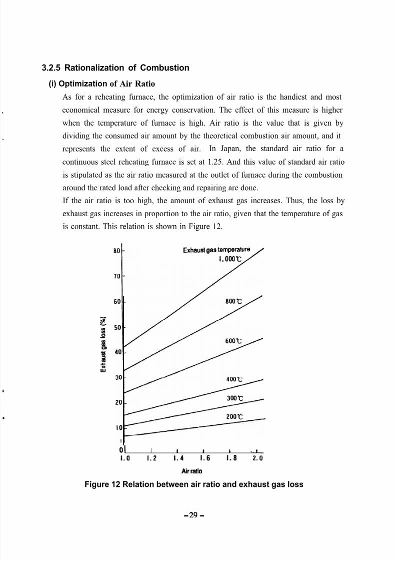
If the air ratio is too high, the amount of exhaust gas increases. Thus, the loss by
exhaust gas increases in proportion to the air ratio, given that the temperature of gas
is constant. This relation is shown in Figure 12.
Exhaust gas WmperatUre
I, ooot/
0 1 I I 1 I II . 0 1.2 1.4 1.6 I.8 -2.0
Air ratio
Figure 12 Relation between air ratio and exhaust gas loss
- 29 -
5/16/2018 Iron& Steel Industry - slidepdf.com
http://slidepdf.com/reader/full/iron-steel-industry-55ab59521ea6d 34/50
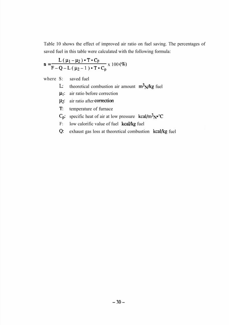
Table 10 shows the effect of improved air ratio on fuel saving. The percentages of
saved fuel in this table were calculated with the following formula:
s =
L ( p l -p 2 ) *T *C p
F - Q - L ( p y - l ) * T * C px 100 (%)
where S:
L:
c 1 1 :
cL2:
T:
c,:
F:
Q:
saved fuel
theoretical combustion air amount m3N/kg fuel
air ratio before correction
air ratio after cortection
temperature of furnace
specific heat of air at low pressure kcal/m3N*“C
low calorific value of fuel kcal/kg fuel
exhaust gas loss at theoretical combustion kcal/kg fuel
-3o-

5/16/2018 Iron& Steel Industry - slidepdf.com
http://slidepdf.com/reader/full/iron-steel-industry-55ab59521ea6d 35/50
Table 10 Percentage of fuel saved when air ratio is corrected
(case of heavy oil)
Furnacetemperature
(“C>
700
900
1100
1300
Ai r r a t i obefore
correction
1.70
1.60
1.50
1.40
1.30
1.20
1.10
1.70
1.60
1.50
1.40
1.30
1.20
1.10
1.70
1.60
1.50
1.40
1.30
1.20
1.10
1.701.60
1.50
1.40
1.30
1.20
1.10
r 1.40
11.6
7.72
3.86
-
-
-
-
18.7
12.5
6.23
-
-
-
-
30.8
20.6
10.3
-
-
-
55.036.7
18.3
-
-
-
-
Air ratio after correction
1.30
14.9
11.1
7.43
3.76
-
-
-
23.5
17.6
11.7
5.94
-
-
-
37.3
28.0
18.6
9.43
-
-
-
61.9
46.5
31.0
15.7
-
-
-
1.20 1.10
17.9 20.8
14.3 17.3
10.7 13.8
7.27 10.5
3.65 7.01
- 3.48
- -
27.7 31.5
22.2 26.3
16.6 21.0
11.3 16.0
5.66 10.7
- 5.29
- -
42.6 47.1
34.1 39.3
25.6 31.4
17.3 23.8
8.67 15.9
- 7.91
- -
67.1 70.9
53.6 59.1
40.2 47.3
27.2 35.9
13.7 23.9
- 11.9
- -
1.00
23.4
20.1
16.7
13.5
10.1
6.74
3.38
34.9
29.9
25.0
20.2
15.2
10.1
5.06
51.0
43.7
36.4
29.4
22.1
14.7
7.36
74.0
63.4
52.9
42.7
32.1
21.3
10.7
-3l-
5/16/2018 Iron& Steel Industry - slidepdf.com
http://slidepdf.com/reader/full/iron-steel-industry-55ab59521ea6d 36/50
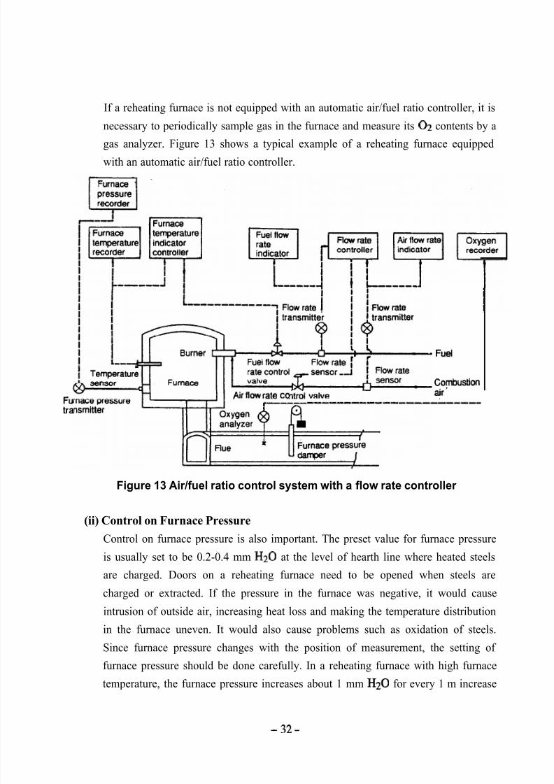
If a reheating furnace is not equipped with an automatic air/fuel ratio controller, it is
necessary to periodically sample gas in the furnace and measure its 02 contents by a
gas analyzer. Figure 13 shows a typical example of a reheating furnace equipped
with an automatic air/fuel ratio controller.
Fuel
Combustion
Fu
tra
Air flow rate co air’---___---------~-----
Figure 13 Air/fuel ratio control system with a flow rate controller
(ii) Control on Furnace Pressure
Control on furnace pressure is also important. The preset value for furnace pressure
is usually set to be 0.2-0.4 mm Hz0 at the level of hearth line where heated steels
are charged. Doors on a reheating furnace need to be opened when steels are
charged or extracted. If the pressure in the furnace was negative, it would cause
intrusion of outside air, increasing heat loss and making the temperature distribution
in the furnace uneven. It would also cause problems such as oxidation of steels.
Since furnace pressure changes with the position of measurement, the setting of
furnace pressure should be done carefully. In a reheating furnace with high furnace
temperature, the furnace pressure increases about 1 mm Hz0 for every 1 m increase
-32-
5/16/2018 Iron& Steel Industry - slidepdf.com
http://slidepdf.com/reader/full/iron-steel-industry-55ab59521ea6d 37/50
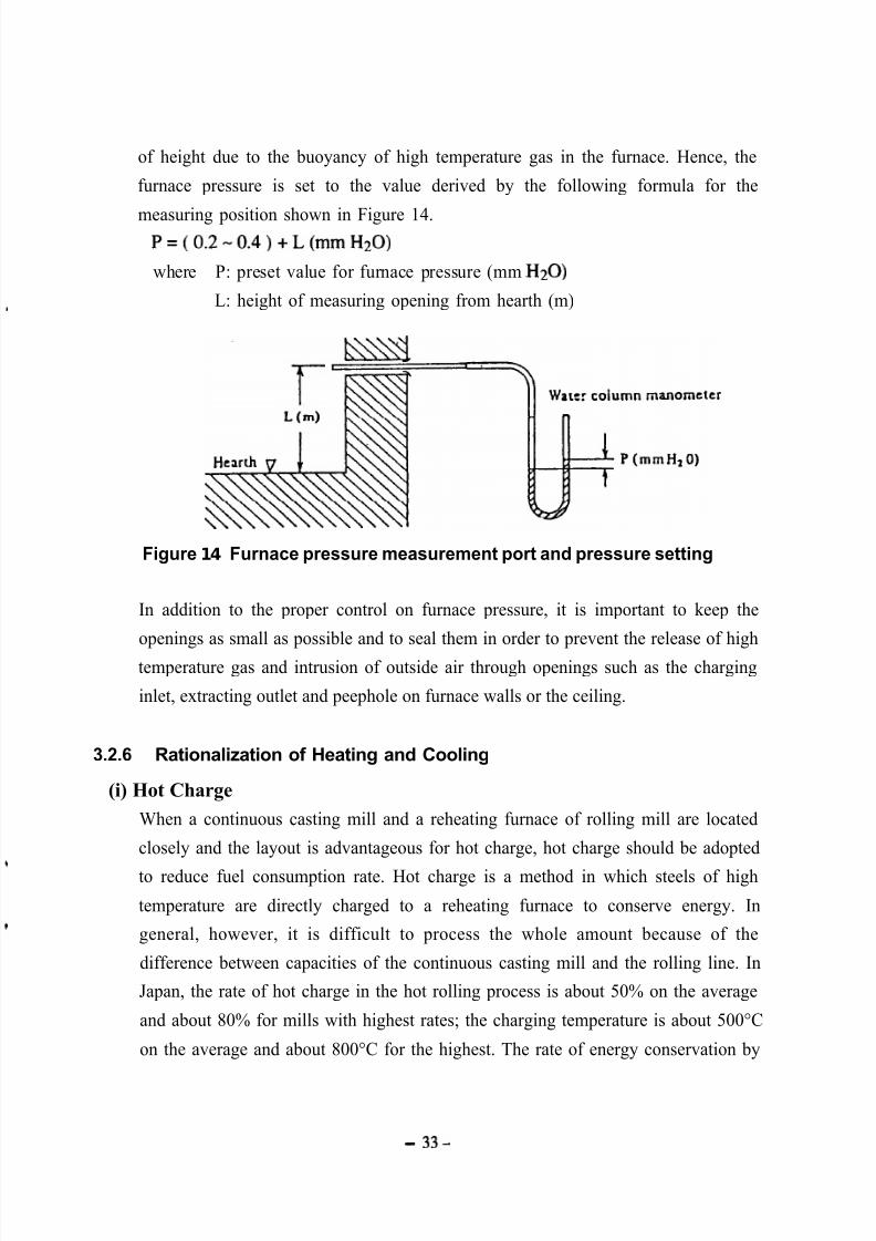
of height due to the buoyancy of high temperature gas in the furnace. Hence, the
furnace pressure is set to the value derived by the following formula for the
measuring position shown in Figure 14.P = ( 0 . 2 - 0 . 4 ) + L ( m m H 2 0 )
where P: preset value for furnace pressure (mm H20)
L: height of measuring opening from hearth (m)
Figure 1 4 Furnace pressure measurement port and pressure setting
In addition to the proper control on furnace pressure, it is important to keep the
openings as small as possible and to seal them in order to prevent the release of high
temperature gas and intrusion of outside air through openings such as the charging
inlet, extracting outlet and peephole on furnace walls or the ceiling.
3.2.6 Rationalization of Heating and Cooling
(i) Hot Charge
When a continuous casting mill and a reheating furnace of rolling mill are located
closely and the layout is advantageous for hot charge, hot charge should be adopted
to reduce fuel consumption rate. Hot charge is a method in which steels of high
temperature are directly charged to a reheating furnace to conserve energy. In
general, however, it is difficult to process the whole amount because of the
difference between capacities of the continuous casting mill and the rolling line. In
Japan, the rate of hot charge in the hot rolling process is about 50% on the average
and about 80% for mills with highest rates; the charging temperature is about 500°C
on the average and about 800°C for the highest. The rate of energy conservation by
- 3 3 -
5/16/2018 Iron& Steel Industry - slidepdf.com
http://slidepdf.com/reader/full/iron-steel-industry-55ab59521ea6d 38/50
hot charge is 20 x 103 k & t per 100°C charging temperature. Thus, a large amount
of energy can be saved by raising the percentage and temperature of hot charge.
3.2.7 Prevention of Heat Loss by Radiation and Transmission
The heat loss from a reheating furnace is largely divided into; 1. radiation loss through
openings and surface of the furnace body, 2. cooling loss through water cooled skid pipes,
3. heat accumulation loss to internal insulation and members composing the furnace body.
Here, the heat accumulation loss can be ignored, if operation is continued for a certain
period of time without much change in temperature as is the case with a continuous steel
reheating furnace.
(i) Prevention of Radiation Heat Loss from Surface of Furnace
a) Quantity of heat release from surface of furnace
The quantity of heat release from surface of furnace body is the sum of natural
convection and thermal radiation. This quantity can be calculated from surface
temperatures of furnace. The temperatures on furnace surface should be measured
at as many points as possible, and their average should be used. If the number of
measuring points is too small, the error becomes large.
The quantity (Q) of heat release from a reheating furnace installed in the building of
a factory is calculated with the following formula:
Q = a x ( tl - t2 )514 + 4.88 E { ( w&3)4-( y3 )4)
where
a : factor regarding to the direction of the surface of natural convection
ceiling = 2.8, side walls = 2.2, hearth = 1.5
tl : temperature of external wall surface of the furnace (°C)
t2 : temperature of air around the furnace (°C)
E: emissivity of external wall surface of the furnace
The first term of the formula above represents the quantity of heat release by natural
convection, and the second term represents the quantity of heat release by radiation.
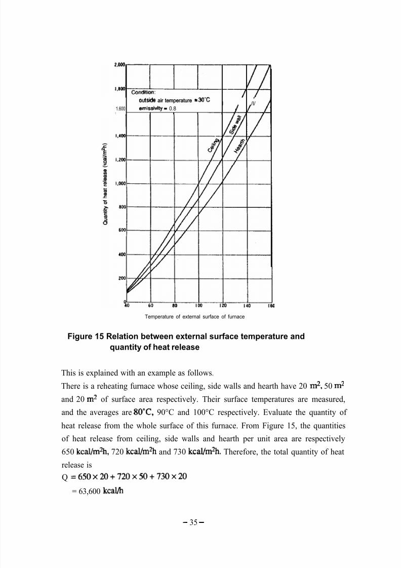
Figure 15 shows the relation between the temperature of external wall surface and
the quantity of heat release calculated with this formula.
-34-
5/16/2018 Iron& Steel Industry - slidepdf.com
http://slidepdf.com/reader/full/iron-steel-industry-55ab59521ea6d 39/50
outsids air temperature - WCutsids air temperature - WC I /I/ = 0.81.600 emissivity
Temperature of external surface of furnace
Figure 15 Relation between external surface temperature and
quantity of heat release
This is explained with an example as follows.
There is a reheating furnace whose ceiling, side walls and hearth have 20 m2, 50 m2
and 20 m2 of surface area respectively. Their surface temperatures are measured,
and the averages are 8O”C, 90°C and 100°C respectively. Evaluate the quantity of
heat release from the whole surface of this furnace. From Figure 15, the quantities
of heat release from ceiling, side walls and hearth per unit area are respectively
650 k&/m%, 720 kcal/m2h and 730 kcal/m2h. Therefore, the total quantity of heat
release is
Q =650x20+720x50+730x20
= 63,600 kcal/h
- 35 -
5/16/2018 Iron& Steel Industry - slidepdf.com
http://slidepdf.com/reader/full/iron-steel-industry-55ab59521ea6d 40/50
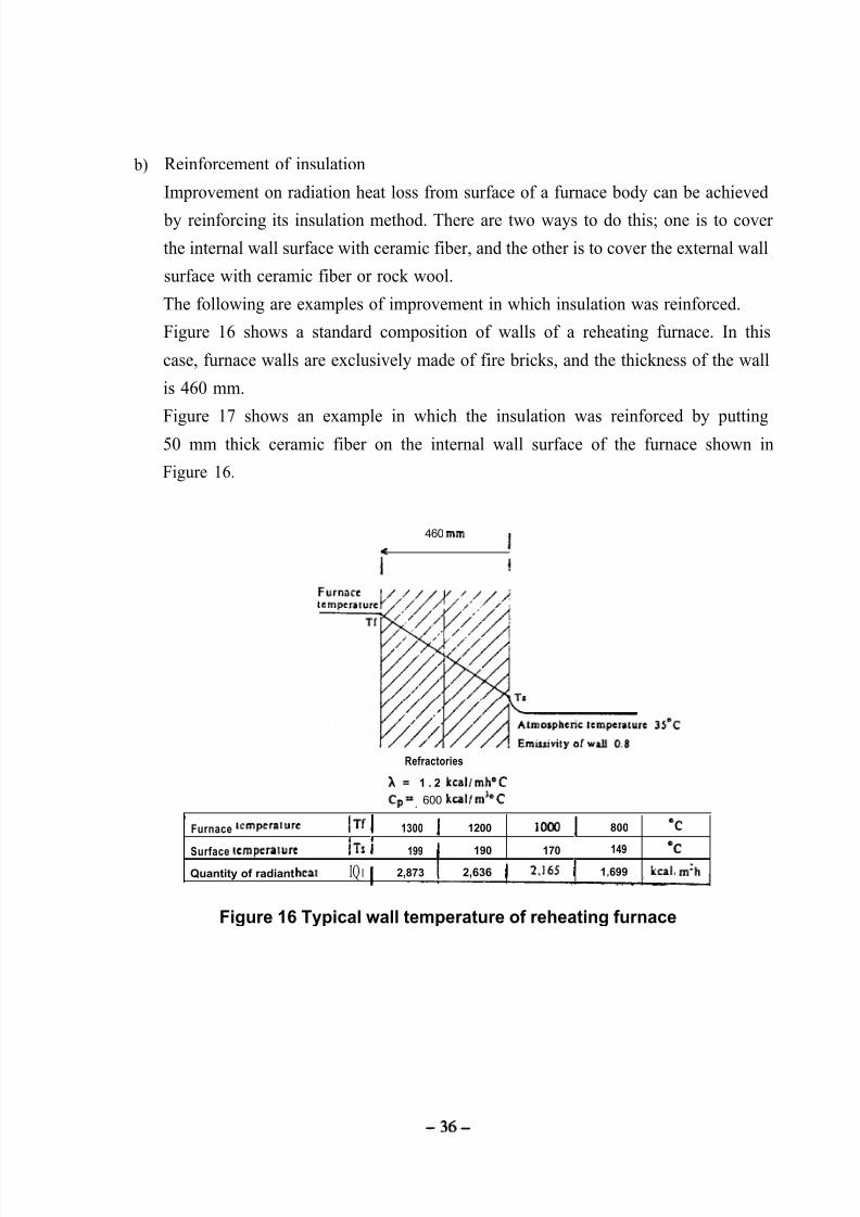
b) Reinforcement of insulation
Improvement on radiation heat loss from surface of a furnace body can be achieved
by reinforcing its insulation method. There are two ways to do this; one is to cover
the internal wall surface with ceramic fiber, and the other is to cover the external wall
surface with ceramic fiber or rock wool.
The following are examples of improvement in which insulation was reinforced.
Figure 16 shows a standard composition of walls of a reheating furnace. In this
case, furnace walls are exclusively made of fire bricks, and the thickness of the wall
is 460 mm.
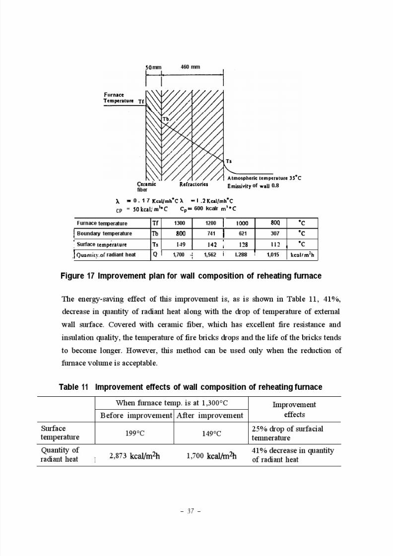
Figure 17 shows an example in which the insulation was reinforced by putting50 mm thick ceramic fiber on the internal wall surface of the furnace shown in
Figure 16.
460 mm
<I
I!
Refractories
,
X = 1 . 2 kcal/mh”C
Cp =, 600 kcal/mJoC
Furnace wmpcralurc
Surface temperalure
Quantity of radiant heat
I’IT 1 1300 1 1200 1000 1 800 ‘C4 I
Ifs I 199 ( 190 170 149 OC
IQ I 1 2,873 2,636 ( 2.165 1 1.699 kcal, m’h
Figure 16 Typical wall temperature of reheating furnace
-36-
5/16/2018 Iron& Steel Industry - slidepdf.com
http://slidepdf.com/reader/full/iron-steel-industry-55ab59521ea6d 41/50
5/16/2018 Iron& Steel Industry - slidepdf.com
http://slidepdf.com/reader/full/iron-steel-industry-55ab59521ea6d 42/50
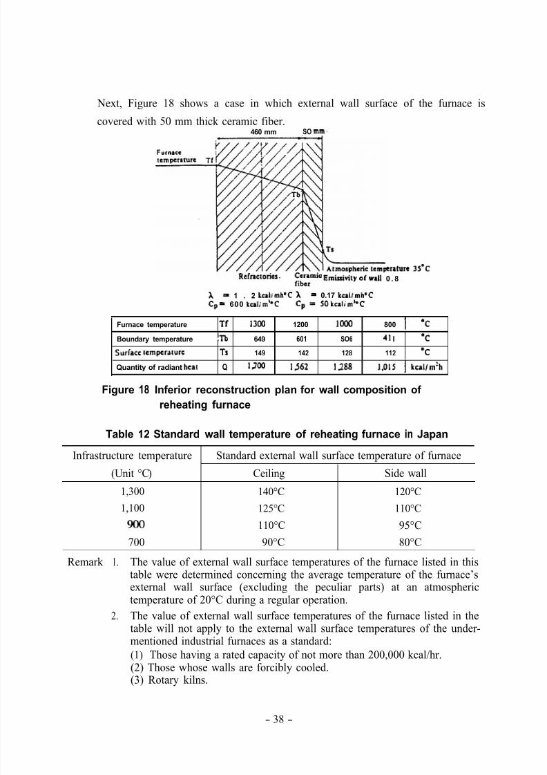
Next, Figure 18 shows a case in which external wall surface of the furnace is
covered with 50 mm thick ceramic fiber.
460 mm SO mm.
eraturc 3S’CRefnc:ories. ;;e;mic Emissivity of ~11 0 . 8
A = 1 . 2 cal/mheC A = 0.17 kcal/mh’C
Cp = 600 kulim’°C Cp = 50kcalid°C
Furnace temperature l-f 13lm 1200 loo0 800 1 ‘c
Boundary temperature ‘l-b 649 601 SO6 41 I ‘C
SurCacc tcmpcriiturc Ts 149 142 128 112 ‘C
Quantity of radiant heat Q lm 1562 1288 I.015 1 kcal/m’h
Figure 18 Inferior reconstruction plan for wall composition of
reheating furnace
Table 12 Standard wall temperature of reheating furnace in Japan
Infrastructure temperature Standard external wall surface temperature of furnace
(Unit °C) Ceiling Side wall
1,300 140°C 120°C
1,100 125°C 110°C
110°C 95°C
700 90°C 80°C
Remark 1. The value of external wall surface temperatures of the furnace listed in thistable were determined concerning the average temperature of the furnace’sexternal wall surface (excluding the peculiar parts) at an atmospherictemperature of 20°C during a regular operation.
2. The value of external wall surface temperatures of the furnace listed in thetable will not apply to the external wall surface temperatures of the under-mentioned industrial furnaces as a standard:
(1) Those having a rated capacity of not more than 200,000 kcal/hr.(2) Those whose walls are forcibly cooled.
(3) Rotary kilns.
- 38 -
5/16/2018 Iron& Steel Industry - slidepdf.com
http://slidepdf.com/reader/full/iron-steel-industry-55ab59521ea6d 43/50
If the external wall surface is covered with steel plates, their temperature will rise
when ceramic fiber is put over the steel plates. And distortion by thermal expansion
may cause a damage to the furnace casing.
For reference, Table 12 shows standard temperatures for the external walls of a
reheating furnace in Japan.
(ii) Prevention of Heat Loss through Openings
Heat loss through openings consists of the heat loss by direct radiation from
openings and the heat loss caused by combustion gas that leaks through openings.
a) Heat loss by radiation from openings
If a furnace body has an opening on it, the heat in the furnace escapes to the outside
as radiant heat.
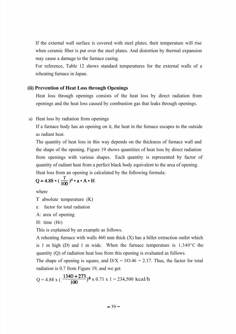
The quantity of heat loss in this way depends on the thickness of furnace wall and
the shape of the opening. Figure 19 shows quantities of heat loss by direct radiation
from openings with various shapes. Each quantity is represented by factor of
quantity of radiant heat from a perfect black body equivalent to the area of opening.
Heat loss from an opening is calculated by the following formula:TQ = 4 . 8 8 * ( m ) 4 * a * A * H
where
T absolute temperature (K)
a: factor for total radiation
A: area of opening
H: time (Hr)
This is explained by an example as follows.
A reheating furnace with walls 460 mm thick (X) has a billet extraction outlet which
is 1 m high (D) and 1 m wide. When the furnace temperature is 1,340°C the
quantity (Q) of radiation heat loss from this opening is evaluated as follows.
The shape of opening is square, and D/X = l/O.46 = 2.17. Thus, the factor for total
radiation is 0.7 from Figure 19, and we get
Q = 4.88 x ( 134;; 273 )“ x 0.71 x 1 = 234,500 kcal/h
- 39 -
5/16/2018 Iron& Steel Industry - slidepdf.com
http://slidepdf.com/reader/full/iron-steel-industry-55ab59521ea6d 44/50
1 . 0 0
0 . 9 0
0 . 8 0
0 . 7 0
0 . 6 0
0 . 5 0
i l . 4 0
0 . 3 0
,0.20
0.10
00.20.40.60.8L0 2 3 4 5 6
R a t i o :Diameter or minimum width D=-Thickness of wail X
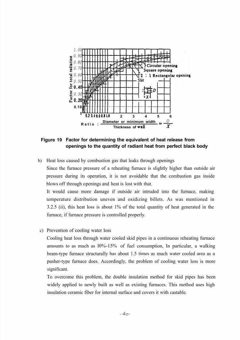
Figure 19 Factor for determining the equivalent of heat release from
openings to the quantity of radiant heat from perfect black body
b) Heat loss caused by combustion gas that leaks through openings
Since the furnace pressure of a reheating furnace is slightly higher than outside air
pressure during its operation, it is not avoidable that the combustion gas insideblows off through openings and heat is lost with that.
It would cause more damage if outside air intruded into the furnace, making
temperature distribution uneven and oxidizing billets. As was mentioned in
3.2.5 (ii), this heat loss is about 1% of the total quantity of heat generated in the
furnace, if furnace pressure is controlled properly.
c) Prevention of cooling water loss
Cooling heat loss through water cooled skid pipes in a continuous reheating furnace
amounts to as much as l0%-15% of fuel consumption, In particular, a walking
beam-type furnace structurally has about 1.5 times as much water cooled area as a
pusher-type furnace does. Accordingly, the problem of cooling water loss is more
significant.
To overcome this problem, the double insulation method for skid pipes has been
widely applied to newly built as well as existing furnaces. This method uses high
insulation ceramic fiber for internal surface and covers it with castable.
- 4 o -
5/16/2018 Iron& Steel Industry - slidepdf.com
http://slidepdf.com/reader/full/iron-steel-industry-55ab59521ea6d 45/50
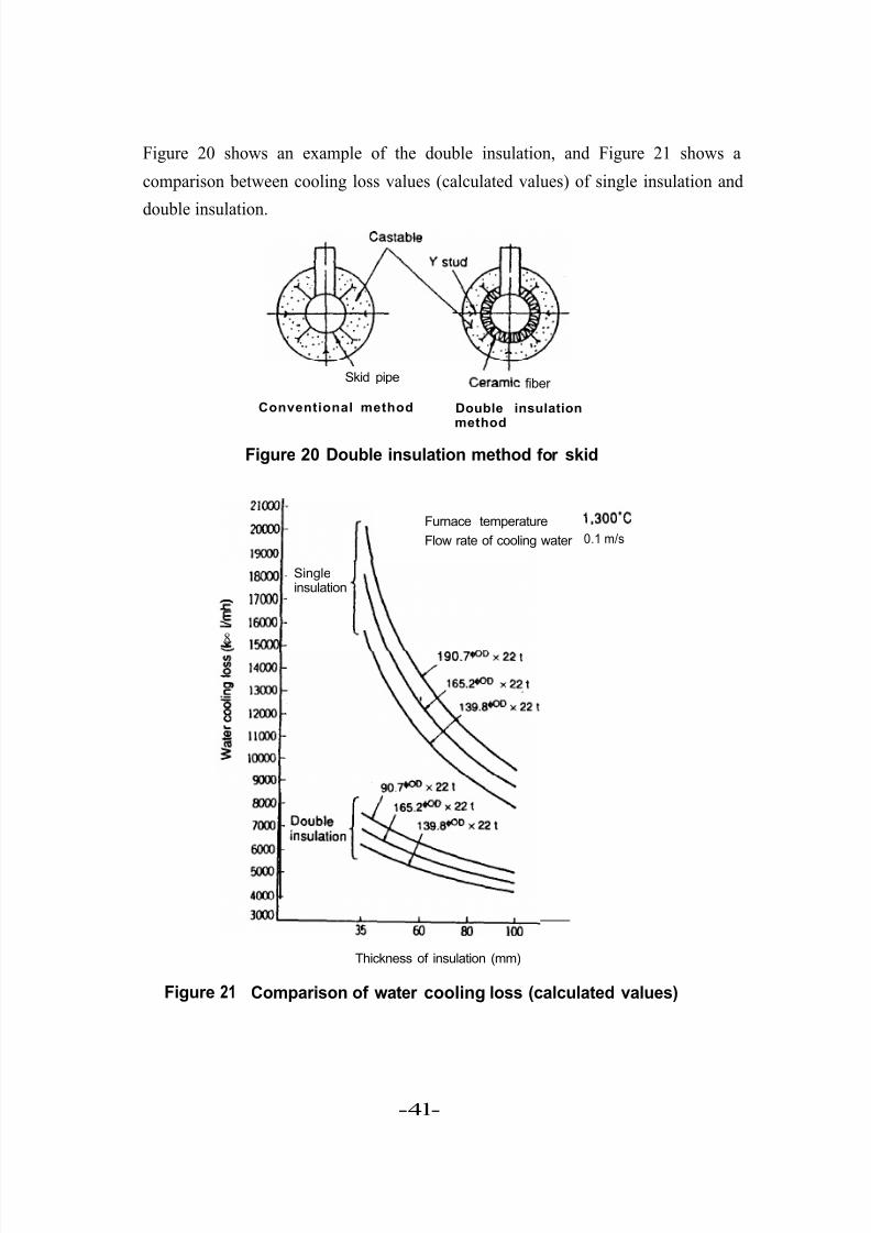
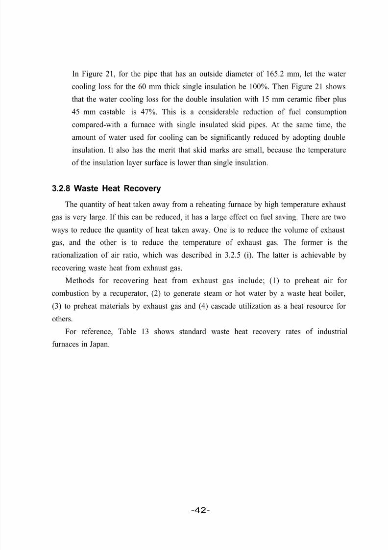
Figure 20 shows an example of the double insulation, and Figure 21 shows a
comparison between cooling loss values (calculated values) of single insulation and
double insulation.
Skid pipeCdrarA fiber
Conventional method Double insulationmethod
Figure 20 Double insulation method for skid
Furnace temperature
Flow rate of cooling water
18000 _ Single
1
insulation= 17aIo-
!z 1m-
8g 15ooo
Thickness of insulation (mm)
1,300’C
0.1 m/s
Figure 21 Comparison of water cooling loss (calculated values)
-4l-
5/16/2018 Iron& Steel Industry - slidepdf.com
http://slidepdf.com/reader/full/iron-steel-industry-55ab59521ea6d 46/50
In Figure 21, for the pipe that has an outside diameter of 165.2 mm, let the water
cooling loss for the 60 mm thick single insulation be 100%. Then Figure 21 shows
that the water cooling loss for the double insulation with 15 mm ceramic fiber plus
45 mm castable is 47%. This is a considerable reduction of fuel consumption
compared-with a furnace with single insulated skid pipes. At the same time, the
amount of water used for cooling can be significantly reduced by adopting double
insulation. It also has the merit that skid marks are small, because the temperature
of the insulation layer surface is lower than single insulation.
3.2.8 Waste Heat RecoveryThe quantity of heat taken away from a reheating furnace by high temperature exhaust
gas is very large. If this can be reduced, it has a large effect on fuel saving. There are two
ways to reduce the quantity of heat taken away. One is to reduce the volume of exhaust
gas, and the other is to reduce the temperature of exhaust gas. The former is the
rationalization of air ratio, which was described in 3.2.5 (i). The latter is achievable by
recovering waste heat from exhaust gas.
Methods for recovering heat from exhaust gas include; (1) to preheat air for
combustion by a recuperator, (2) to generate steam or hot water by a waste heat boiler,
(3) to preheat materials by exhaust gas and (4) cascade utilization as a heat resource for
others.
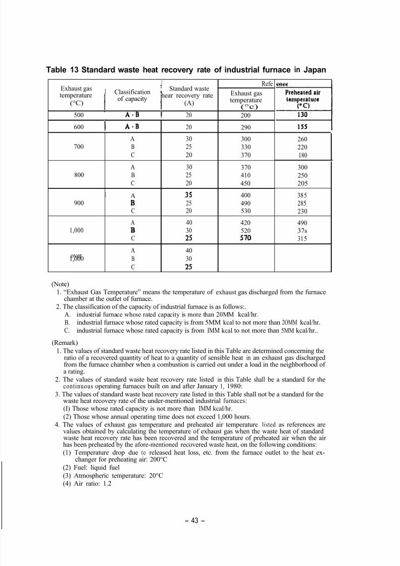
For reference, Table 13 shows standard waste heat recovery rates of industrial
furnaces in Japan.
-42-
5/16/2018 Iron& Steel Industry - slidepdf.com
http://slidepdf.com/reader/full/iron-steel-industry-55ab59521ea6d 47/50
Table 13 Standard waste heat recovery rate of industrial furnace in Japan
Standard waste
temperature
I
I
Exhaust gas iRefe
(°C)
500
600
700
800
900
1,000
over1,000
!
Classification
of capacity hear recovery rateI
Exhaust gas
(A) temperature(°c)
A.B ! 20 200
1 A-B 20 290
A 30 300
B 25 330
C 20 370
A 30 370
B 25 410
C 20 450
IA 3s 400B 25 490C 20 530
A 40 420
B 30 520C 25 570
A 40
B 30
C 25
cncc
260
220
180
300
250
205
385285
230
490
37s
315
(Note)
1. “Exhaust Gas Temperature” means the temperature of exhaust gas discharged from the furnacechamber at the outlet of furnace.
2. The classification of the capacity of industrial furnace is as follows:.A. industrial furnace whose rated capacity is more than 20MM kcal/hr.
B. industrial furnace whose rated capacity is from 5MM kcal to not more than 2OMM kcal/hr.
C. industrial furnace whose rated capacity is from IMM kcal to not more than 5MM kcal/hr..
(Remark)
1. The values of standard waste heat recovery rate listed in this Table are determined concerning theratio of a recovered quantity of heat to a quantity of sensible heat in an exhaust gas dischargedfrom the furnace chamber when a combustion is carried out under a load in the neighborhood of a rating.
2. The values of standard waste heat recovery rate listed in this Table shall be a standard for thecontinuous operating furnaces built on and after January 1, 1980:
3. The values of standard waste heat recovery rate listed in this Table shall not be a standard for thewaste heat recovery rate of the under-mentioned industrial furnaces:
(I) Those whose rated capacity is not more than IMM kcal/hr.
(2) Those whose annual operating time does not exceed 1,000 hours.
4. The values of exhaust gas temperature and preheated air temperature listed as references arevalues obtained by calculating the temperature of exhaust gas when the waste heat of standardwaste heat recovery rate has been recovered and the temperature of preheated air when the airhas been preheated by the afore-mentioned recovered waste heat, on the following conditions:
(1) Temperature drop due t o released heat loss, etc. from the furnace outlet to the heat ex-changer for preheating air: 200°C
(2) Fuel: liquid fuel
(3) Atmospheric temperature: 20°C
(4) Air ratio: 1.2
- 43 -
5/16/2018 Iron& Steel Industry - slidepdf.com
http://slidepdf.com/reader/full/iron-steel-industry-55ab59521ea6d 48/50
Now, we will describe preheating of the air for combustion, which is generally done
for reheating furnaces.
(i) Preheating the Air for Combustion by a Recuperator
A recuperator is a device that recovers heat from exhaust gas exhausted from a
reheating furnace. A metallic recuperator has heat transfer surface made of metal,
and a ceramic recuperator has heat transfer surface made of ceramics.
When the exhaust gas temperature is lower than 1,000°C and air for combustion is
preheated, a metallic recuperator is used in general.
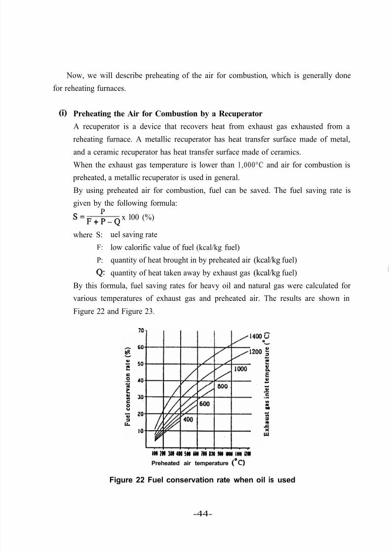
By using preheated air for combustion, fuel can be saved. The fuel saving rate isgiven by the following formula:
P
‘ = F + P - Qx l00 (%)
where S:
F:
P:
Q:
uel saving rate
low calorific value of fuel (kcal/kg fuel)
quantity of heat brought in by preheated air (kcal/kg fuel)
quantity of heat taken away by exhaust gas (kcal/kg fuel)
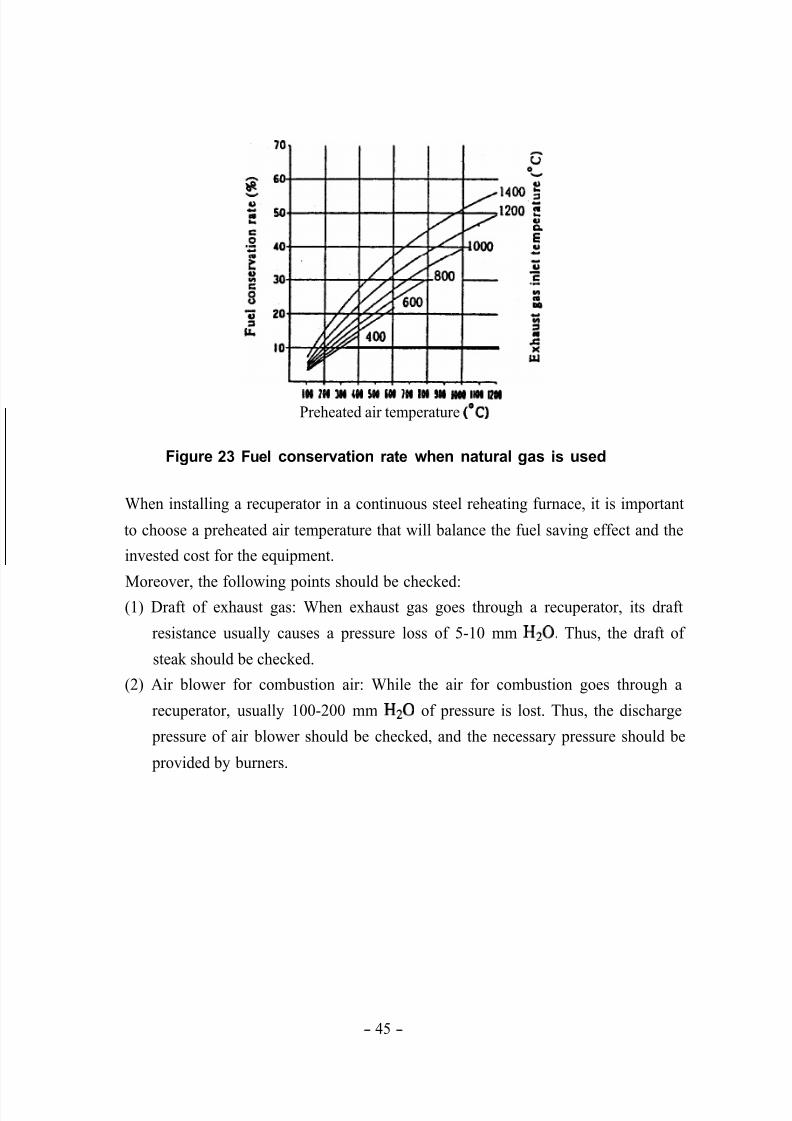
By this formula, fuel saving rates for heavy oil and natural gas were calculated forvarious temperatures of exhaust gas and preheated air. The results are shown in
Figure 22 and Figure 23.
l o l t n 3 M Ml Ml m I l l 1 2 4 m wo ( I I n l l w
Preheated air temperature (“C)
Figure 22 Fuel conservation rate when oil is used
-44-
5/16/2018 Iron& Steel Industry - slidepdf.com
http://slidepdf.com/reader/full/iron-steel-industry-55ab59521ea6d 49/50
I W ? @I Ml @I 5 0 0 I # l OI I M I DI I OM I I W Q#
Preheated air temperature (‘CT)
Figure 23 Fuel conservation rate when natural gas is used
When installing a recuperator in a continuous steel reheating furnace, it is important
to choose a preheated air temperature that will balance the fuel saving effect and the
invested cost for the equipment.
Moreover, the following points should be checked:(1) Draft of exhaust gas: When exhaust gas goes through a recuperator, its draft
resistance usually causes a pressure loss of 5-10 mm H20. Thus, the draft of
steak should be checked.
(2) Air blower for combustion air: While the air for combustion goes through a
recuperator, usually 100-200 mm Hz0 of pressure is lost. Thus, the discharge
pressure of air blower should be checked, and the necessary pressure should be
provided by burners.
- 45 -
5/16/2018 Iron& Steel Industry - slidepdf.com
http://slidepdf.com/reader/full/iron-steel-industry-55ab59521ea6d 50/50
Conclusion
If we divide energy conservation measures of the industrial sector in a general manner,we come up with the following three approaches.
Phase 1 is primarily a plan for the complete improvement of operating conditions in
stages by strengthening energy management, based on the assumption of existing
facilities.
Phase 2 is designed for carrying out only partial improvement of facilities. This phase
stresses decreasing energy consumption and plans for more efficient use of energy exhaust
emissions.
Phase 3 concentrates on the development of a new process for energy conservation
and on plans for a fundamental restructuring of the manufacturing process.
This manual has been mainly concerned with introducing Phase 1. These measures
are comparatively simple, and there are many cases where they are not very effective in
saving energy. However, the overall effectiveness of these accumulated cases was greater
than expected. Certainly, based on this manual, we hope that the facilities being dealt with
will be reevaluated with new insight and that concrete measures may be soundly
implemented.In addition, even for measures which have already been implemented, we hope that
you will recheck whether or not they have produced results in regards to the energy
savings being targeted, and that, if necessary, improvements in heightening efficiency will
be made.
References
1. Handbook of Iron and Steel.
2. Handbook of Energy Conservation for Industrial Furnaces, Japan Industrial Furnace
Association.
3. Data Sheet for Energy Management (l), Energy Conservation Center.
4. Iron and Steel, vo1.64, no. 13 (1978).
5. Refractory Material, no.178, vol.24 (1972).
- 46 -