investigation of soil resistivity base on design of an...
TRANSCRIPT
INVESTIGATION of SOIL RESISTIVITY BASE on DESIGN
of an EXPERIMENT APPROACH
Abadi bin Mesiran
Bachelor of Electrical Engineering (Power Electronic and Drives)
July 2012
“ I hereby declare that I have read through this report entitle “Investigation of Soil
Resistivity Base on Design of an Experiment Approach” and found that it has comply the
partial fulfillment for awarding the degree of Bachelor of Electrical Engineering (Power
Electronics and Drive)”
Signature : .......................................................
Supervisor‟s Name : Ms. ARFAH BTE AHMAD
Date : 29th JUNE 2012
INVESTIGATION of SOIL RESISTIVITY BASE on DESIGN of an EXPERIMENT
APPROACH
ABADI BIN MESIRAN
A report submitted in partial fulfillment of the requirements for the Bachelor Of Electrical Engineering (Power Electronics and Drive)
Faculty of Electrical Engineering UNIVERSITI TEKNIKAL MALAYSIA MELAKA
2011/2012
I declare that this report entitle “Investigation of Soil Resistivity Base on Design of an
Experiment Approach” is the result of my own research except as cited in the references.
The report has not been accepted for any degree and is not concurrently submitted in
candidature of any other degree.
Signature : ..........................................................
Name : ABADI BIN MESIRAN
Date : 29th JUNE 2012

To my beloved Mother and father
ii
ACKNOWLEDGEMENT
“In the name of ALLAH the Most Gracious, the Compassionate Merciful”
Praise to Allah S.W.T. the Lord of the universe, for his wisdom, strength and blessing.
Without His Grace and Mercifulness, this report may not be completed on time. Peace and
blessings of Allah be upon His Messenger, Muhammad S.W.T.
I would like to kindly thank all those who helped me with their valuable support during my
research to accomplish my degree research.
First and foremost, I would like to thank and appreciate my supervisor Ms. Arfah bte
Ahmad for her helpful guidelines, contribution and support throughout my research.
I also would like to express my utmost gratefulness and appreciation to my friends and
colleagues for contributing ideas and suggestion. Also for their kindness and big support
for complete my research.
At last but not least I would like to appreciate my parents which I owe a big debt of
attitude to them for their full support during my entire life.
iii
ABSTRACT
According to National Electric Code (NEC), ground can be defined as a conduction
connection, whether intentional or accidental between an electrical circuit or equipment,
and the earth, or to some conducting body that serves in place of the earth. The purpose of
an earthing system is to provide a safe path for the dissipation of Fault Current (FC),
lightning strike, static discharge, EMI and RFI signals and interference; this is in additional
to the safety of the personnel and machinery. Generally, in electrical engineering field,
grounding is a vital action. Any fault implicates or involving the ground, large current and
raised potential occur which is can be considered as out of normal operating conditions.
Soil resistivity testing is a crucial technique or action that must be taken before committing
the grounding system. It will determine the impedance of the soil and identify the factors
that can affect the resistivity of the soil. The properties or the characteristics of the soil will
determine the level or the degree of the soil resistivity. Soil resistivity normally varies
according to the conditions of the environment. In this research, two types of soil will be
taken as a test subject. The aim of this study is to determine the factors that affect the soil
resistivity, to identify the best soil between clay and peat moss for grounding purpose and
finally, to analyze the effects of each factor to soil resistivity by using factorial design.
Clay, laterite and peat moss with control amount of several materials that represent as
natural factors that affecting the soil resistivity will undergo a periodic testing. The tool use
for measurement is BS 1377-3. The resistivity values obtain from the test exhibit the
relative capability electric currents from which the corrosiveness of the soil can be
inferred. Final part of this research is compare the result and analyzed the data by using
statistical method.
iv
ABSTRAK
Menurut National Electric Code (NEC), tanah boleh ditakrifkan sebagai sambungan
konduksi, sama ada sengaja atau tidak sengaja antara litar elektrik atau peralatan, dan
bumi, atau beberapa badan menjalankan yang berkhidmat di tempat bumi. Tujuan sistem
pembumian adalah untuk menyediakan satu laluan yang selamat bagi mengelakkan
daripada Kerosakan Semasa (FC), panahan petir, pelepasan statik, EMI dan RFI isyarat
dan gangguan; ini adalah tambahan kepada keselamatan kakitangan dan jentera. Secara
umumnya, dalam bidang kejuruteraan elektrik, pembumian adalah satu tindakan yang
penting. Kerosakan mana-mana bahagian yang melibatkan tanah,berpotensi berlakunya
keadaan yang boleh dianggap sebagai keadaan operasi biasa. Ujian kerintangan tanah
adalah satu teknik penting atau tindakan yang mesti diambil sebelum melakukan sistem
pembumian. Ia akan menentukan galangan tanah dan mengenalpasti faktor-faktor yang
boleh menjejaskan kerintangan tanah. Sifat-sifat atau ciri-ciri tanah akan menentukan tahap
kerintangan tanah. Kerintangan tanah biasanya berbeza-beza mengikut keadaan
persekitaran. Dalam kajian ini, tiga jenis tanah akan diambil sebagai subjek ujian. Tujuan
kajian ini adalah untuk menentukan faktor-faktor yang memberi kesan kerintangan tanah,
untuk mengenal pasti tanah yang terbaik di antara tanah liat, gambut dan merah untuk
tujuan pembumian dan juga untuk menganalisis kesan setiap faktor kerintangan tanah
dengan menggunakan reka bentuk faktorial. Tanah liat, merah dan gambut dengan jumlah
yang tertentu berserta beberapa faktor alam yang mempengaruhi kerintangan tanah akan
menjalani ujian berkala dengan menggunakan alat BS 1377-3. Nilai-nilai kerintangan yang
diperolehi daripada ujian arus keupayaan relatif elektrik dari mana kekakisan tanah boleh
disimpulkan di bahagian akhir kajian ini. Bahagian akhir kajian ini membandingkan
keputusan dan menganalisis data dengan menggunakan kaedah statistik.
v
TABLE OF CONTENTS
CHAPTER TITLE PAGE
ACKNOWLEDGEMENT ii
ABSTRACT iii
ABSTRAK iv
TABLE OF CONTENT v
LIST OF TABLES vii
LIST OF FIGURES viii
LIST OF APPENDIX x
1 INTRODUCTION 1
1.0 Overview 1
1.1 Research Background 2
1.2 Problem Statements 4
1.3 Objectives 5
1.4 Project Scopes 5
2 LITERATURE SURVEY AND THEORY 7
2.1 Introduction 7
2.2 Soil Resistivity 8
2.3 Type of Soil 9
2.4 Water Content 10
2.5 Temperature 13
2.6 Dissolved Salt 15
2.7 Measurement of Soil Resistivity 16
3 PROJECT METHODOLOGY 17
4
vi
4 RESULT & ANALYSIS 22
4.1 Figure Explanation 24
4.2 Scatter plot Analysis 24
4.3 Scatter plot Graph 25
4.3.1 Peat Moss 25
4.3.2 Laterite 26
4.3.3 Clay 27
4.4 Cube Plot Analysis 28
4.6 Line Graph Analysis 31
4.8 The Model Analysis 33
5 DISCUSSION & CONCLUSION 40
5.1 Discussion 40
5.1.1 Discussion on Moisture Test 41
5.1.2 Discussion on Acidity Test 41
5.1.3 Discussion on Soil Test 42
5.2 Conclusion 43
6 RECOMMENDATION
REFERENCES 46
APPENDICES 47
vii
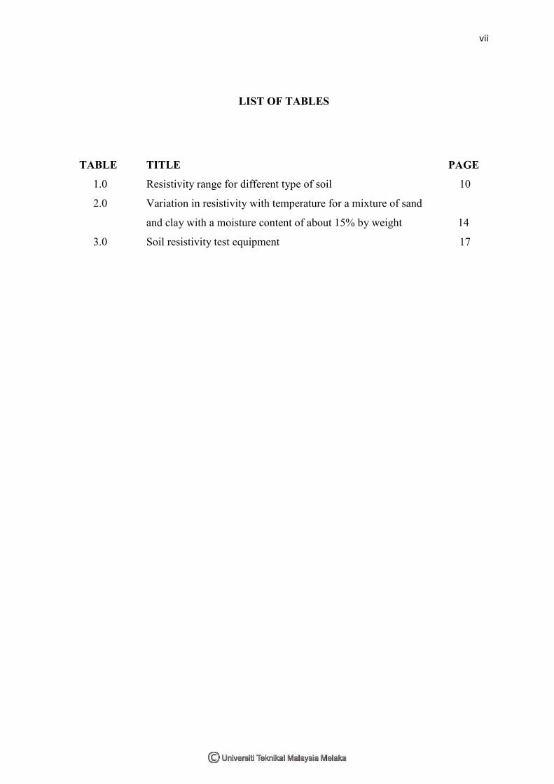
LIST OF TABLES
TABLE TITLE PAGE
1.0 Resistivity range for different type of soil 10
2.0 Variation in resistivity with temperature for a mixture of sand
and clay with a moisture content of about 15% by weight 14
3.0 Soil resistivity test equipment 17
viii
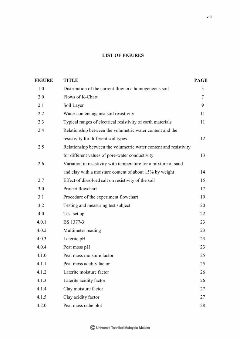
LIST OF FIGURES
FIGURE TITLE PAGE
1.0 Distribution of the current flow in a homogeneous soil 3
2.0 Flows of K-Chart 7
2.1 Soil Layer 9
2.2 Water content against soil resistivity 11
2.3 Typical ranges of electrical resistivity of earth materials 11
2.4 Relationship between the volumetric water content and the
resistivity for different soil types 12
2.5 Relationship between the volumetric water content and resistivity
for different values of pore-water conductivity 13
2.6 Variation in resistivity with temperature for a mixture of sand
and clay with a moisture content of about 15% by weight 14
2.7 Effect of dissolved salt on resistivity of the soil 15
3.0 Project flowchart 17
3.1 Procedure of the experiment flowchart 19
3.2 Testing and measuring test subject 20
4.0 Test set up 22
4.0.1 BS 1377-3 23
4.0.2 Multimeter reading 23
4.0.3 Laterite pH 23
4.0.4 Peat moss pH 23
4.1.0 Peat moss moisture factor 25
4.1.1 Peat moss acidity factor 25
4.1.2 Laterite moisture factor 26
4.1.3 Laterite acidity factor 26
4.1.4 Clay moisture factor 27
4.1.5 Clay acidity factor 27
4.2.0 Peat moss cube plot 28
ix
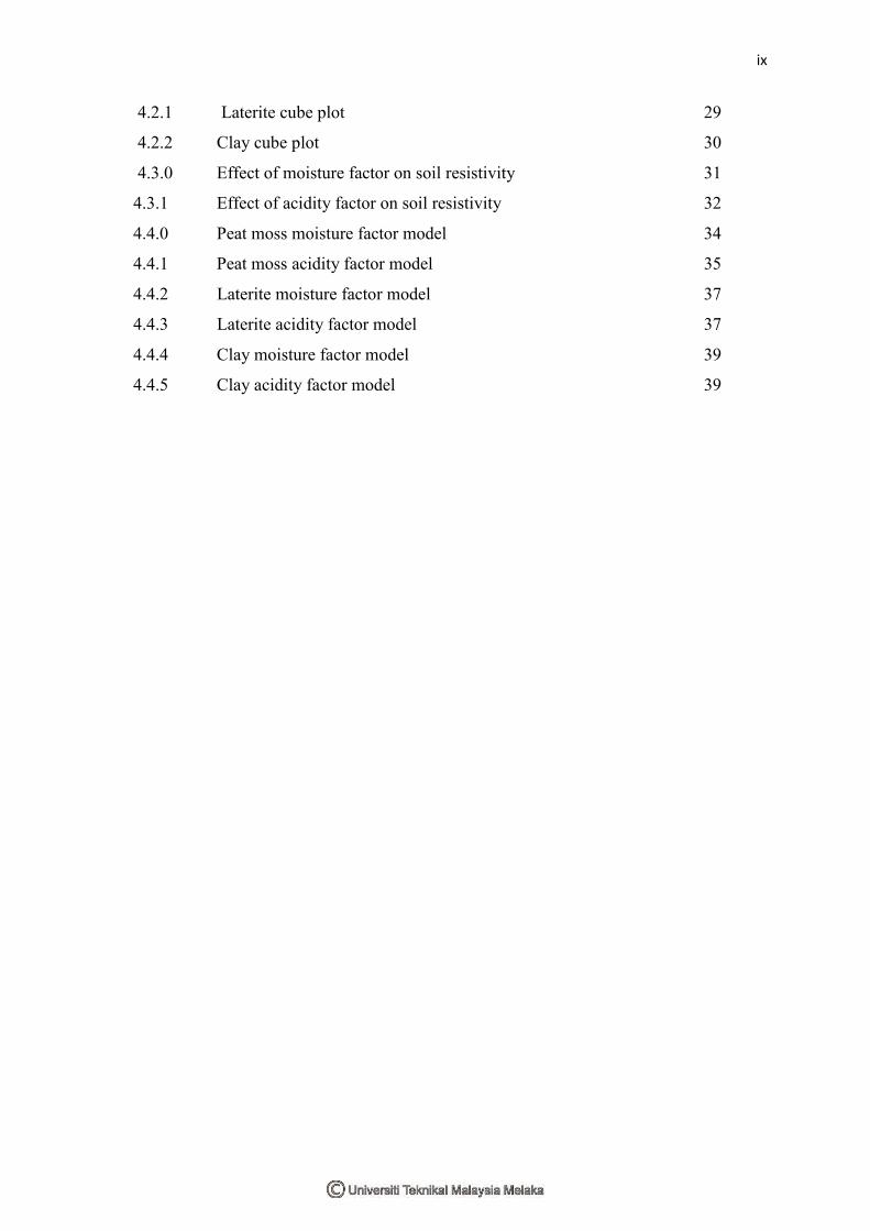
4.2.1 Laterite cube plot 29
4.2.2 Clay cube plot 30
4.3.0 Effect of moisture factor on soil resistivity 31
4.3.1 Effect of acidity factor on soil resistivity 32
4.4.0 Peat moss moisture factor model 34
4.4.1 Peat moss acidity factor model 35
4.4.2 Laterite moisture factor model 37
4.4.3 Laterite acidity factor model 37
4.4.4 Clay moisture factor model 39
4.4.5 Clay acidity factor model 39
x
LIST OF APPENDICES
APPENDIX TITLE PAGE
A Moisture Factor Data 47
B Acidity Factor Data 49
C Peat Moss plot 51
D Laterite Plot 53
E Clay Plot 56
1
CHAPTER 1
INTRODUCTION
1.0 Overview
The earth is actually covered with four different types of layer. The outermost layer
of the earth is called earth crust and this is where the entire living things live and build up
their lives. The earth's crust is actually the thinnest layer among all the layers that build up
the earth. One of the important materials in the earth's crust is soil. Physically, the soil
looks like just a soil and not more than that. However, there are thousand even million
other materials that concentrated in it and that's what makes a soil is a soil. Scientifically,
soil can be described as a natural body consisting of layers of mineral with various
thicknesses and because of that, soil can be characterized to various types [5]. In
conjunction with the characteristics of the soil, one term in electrical field has been
automatically strongly connected with the various soils in this world. The term is
„resistivity‟. Resistivity is a term in an electric field to indicate a barrier or obstacle in a
material [6]. It is inversely proportional with another electrical term which is conductivity.
The higher the resistivity, the lower the conductivity will be and otherwise if the resistivity
is less, then the conductivity will become better. In electrical engineering field, soil
resistivity study is crucial because, any current in this world will be grounded or ended to
earth. So, if the resistivity of a soil is not properly study, there is a possibility that bad
things occur. Several common factors such as type of soil, temperature, humidity or
moisture and acidity that affect the soil resistivity have been listed for further investigation.
2
1.1 Research Background
Voltage can be defined through Ohm‟s law stated as:
V=IR (1)
Ohm‟s Law is one of the basic laws in electrical engineering field. This law was
made up by three important terms which are voltage (V), current (I) and resistance (R).
According to Alexander Sadiku in his books entitle, Third Edition of Fundamental of
Electric Circuit, Ohm‟s Law can be defined as the voltage (V) across a resistor that is
directly proportional to the current (I) flowing through the resistor [1] . The creator of this
law defined the constant of proportionality for a resistor to be a resistance, R. Thus, that is
how the law being created.
Generally, materials have characteristics behaviour of resisting the flow of
electrical charge. The ability to resist current is one of the physical properties that posses
by any materials in this whole world. This physical property also known as resistance and
represented by the symbol, R. Resistivity varies according to the different material. Certain
material posses‟ low resistivity which can be categorized as a good conductor while some
materials have high resistivity which is widely used for insulation process. In addition,
there is a research on producing a material that posse‟s free resistivity and done by a genius
scientist from Europe. This phenomenon is known as superconductivity and the material
produce known as superconductor [11]. While the research is still in progress, the world of
technology today has kept increasing in terms of the quality or the standard in order to
meet the modernization demand. However, behind all these intelligence technologies, only
one term has been highlighted which is the resistivity.
Electrical resistivity of the soil can be considered as a proxy for the variability of
soil physical properties (Banton et al., 1997). The line distributions of the current flow
normally depend on the subject or medium under investigation. This is because they are
physically concentrated in volumes. For a simple body, resistivity, R can be expressed as
follows:
𝜌 = 𝑅(𝑆
𝐿) (2)
Where, R = electrical resistance (Ω)
L = length of the cylinder (m)
S = cross sectional area (𝑚2)
3
The resistance of the electrical of the cylindrical body R (Ω) is defined by the ohm‟s law
which is:
R= 𝑉𝐼 (3)
V= potential different (V)
I = current (A)
Another characteristic that commonly uses in electrical study is described by the
conductivity value σ (S𝑚−1), equal to the mutual or reciprocal of the soil resistivity. Thus:
σ = 1
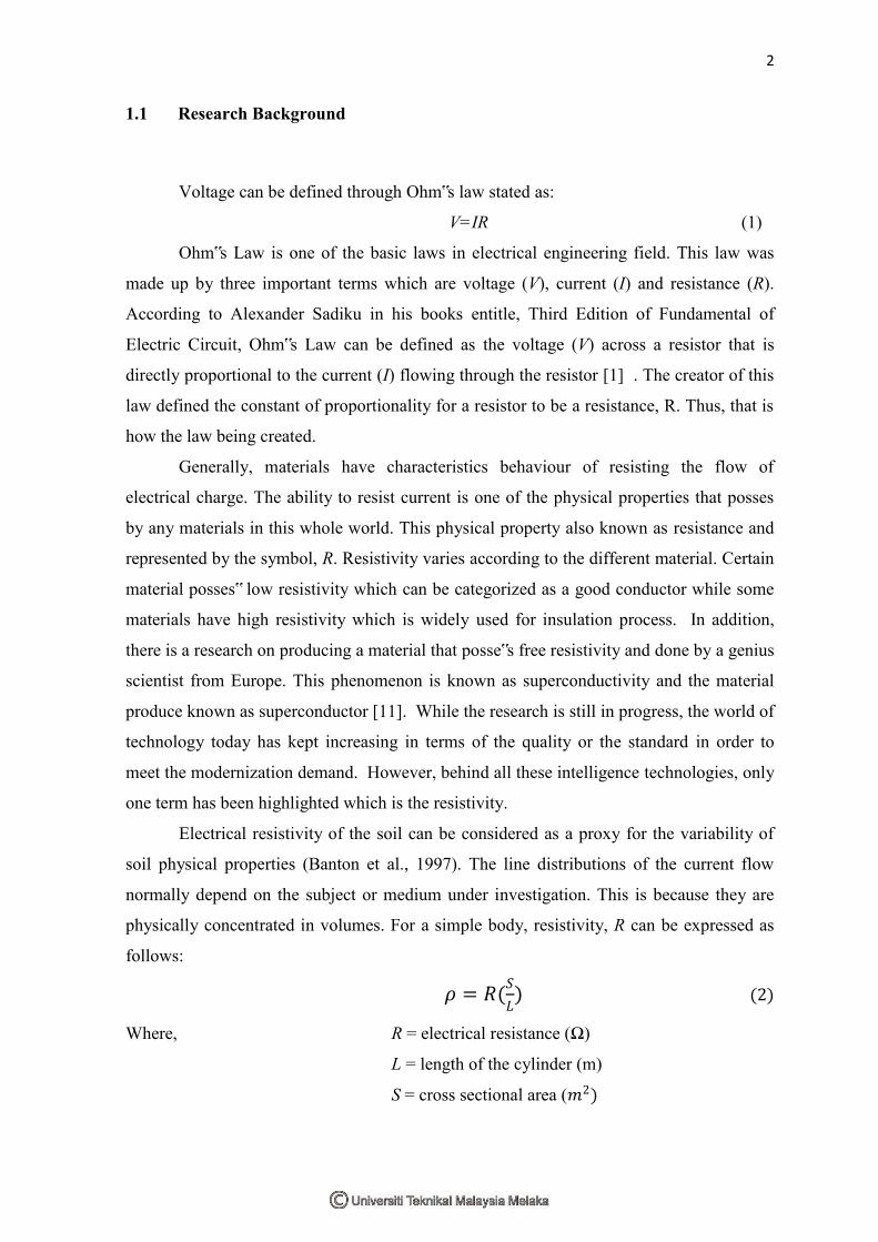
In a homogeneous and isotropic half-space, electrical equipotential are hemispherical when
the current electrodes are located at the soil surface as shown in Fig. 1 (Scollar et al., 1990;
Kearey et al., 2002; Sharma, 1997; Reynolds, 1997). Then, a calculation on current density
J (A/𝑚2) for the entire radial can be determined via the given formulae:
2πr2 is stand for the surface of a hemispherical sphere of radius r. Then the potential
different which is voltage (V) can be defined as:
𝐽 =𝐼
2𝜋𝑟2
V = 𝜌𝑙
2𝜋𝑟
Figure 1.0: distribution of current flow in homogenous soil
(5)
(6)
(4)
4
Soil resistivity normally related to the several factors that affect the degree of the
resistivity. Whether the resistivity is high or low, it will be determined by all the factors.
Normally, factors such as chemical content, water control, temperature, humidity and type
of the soil itself has a strong connection with the degree of the resistivity. Among these
factors there will be specific factors that affect the resistivity of the soil [2].
1.2 Problem Statement
The earth's crust was made by various types of soil. Each soil has their own
characteristics and different utilities. Normally, the characteristics of the soil will be
determined by the location where the soil was found. In other words, current condition of
the location will affect the properties of the soil.
This research is done in order to determine the factors that influence the soil
resistivity. Soil resistivity normally varies according to several factors. Besides that, this
research also intends to identify the best soil among the three soil use in this research
which is clay, laterite and peat moss for grounding purpose. Different type of soil has
different characteristics. So, this research is done in order to determine the best soil for
grounding system. Usually, soil with low resistivity value is the best soil for grounding
purposes because it can let the fault current passing through.
This research is important because it has a direct relation with an electrical field. In
this modern civilization, electrical field has played a big role for bring up the live into the
level in which our standing at. Nowadays, everything in this world is tending to use
electric as the main power and grounding system for electrical is important because it is
one of the ways to protect the consumers. So, if the soil resistivity is not properly studied, a
lot of problems will occur and it will lead to the worst case scenario which is death.
Result from this research will be helpful because the outcomes of this research will
make the grounding procedure easier and effective. Clay, laterite and peat moss are the
most common type of soil in Malaysia. All these three soil certainly posses certain factors
that may affect the resistivity itself. So, it is important that before attempting any
grounding system, soil in the current place need to be identified first and the person who in
charge in attempting grounding system need to be clear about the factors that may affect
5
the resistivity of the soil and how to overcome it. The outcomes of this research will
certainly give a guideline to everybody who required to do the grounding system.
1.3 Objectives
i. To determine the factors that affects the soil resistivity.
ii. To identify the best soil between clay, laterite and peat moss for grounding
purpose.
iii. To analyze the effects of each factors to soil resistivity by using factorial
design.
1.4 Project Scope
This experiment will be stressed on the factors that affecting the soil resistivity. All
the factors will be mingled with the chosen soil. Factors that have been chosen as
manipulated variables are temperature, moisture and acidity. Three types of soil will be
used in this experiment which is clay, laterite and peat moss. All these three soils have
been taken as a test subject because these soils are readily available and have a clear
distinction on its physical properties. One of the factors in affecting the soil resistivity is
acidity. In order to personify the acidity in the soil, sodium chloride will be used.
BS 1377-3 is a soil resistivity tester. The equipment will be used throughout the
study. The test subject will undergo periodic testing and by the time the result obtains all
the data will be analyzed for further discussion. The design of this experiment will be
based on factorial design and the data obtain will be analyzed using statistical method.
To make the project scope clear, the point below will make the project scope clearer:
I. This project is a study on determining and analysis the factors that affect the
soil resistivity.
II. The tool use for measurement is BS 1377-3 which is based on disc electrode
method.
6
III. Disc electrodes are fitted to the end of cylindrical with or without testing
subjects in order to be measured in the laboratory. Voltage will be applied
across the electrodes. Then, the current flowing between them will be measured
and Ohm‟s law will be applied in this situation in order to derive the resistivity
from the test subject.
IV. Apparatus use for measurement of the resistivity are:
Cylindrical container
Two metal disc
DC power source
V. The statistical method will be used to analysis the data.
7
Grounding
System grounding
Equipment grounding
Static & lightning protection grounding
Connection to earth
Method & technique of construction
Measurement of earth
resistance
Ground electrodes
Earth resistance
Soil resistivity
Type of soil
ClayPeat moss
Water content
Effect of chemical
Sodium chloride
Sodium sulfate
Sodium carbonate
Copper sulfate
Soil temperature
Laterite
Measurement of soil resistivity
Wenner probe
Two disc electrode base
on bs1377-3
Resistance of the
electrode
Resistance between
electrode & soil
Electronic equipment grounding
CHAPTER 2
LITERATURE SURVEY AND THEORY
2.1 Introduction
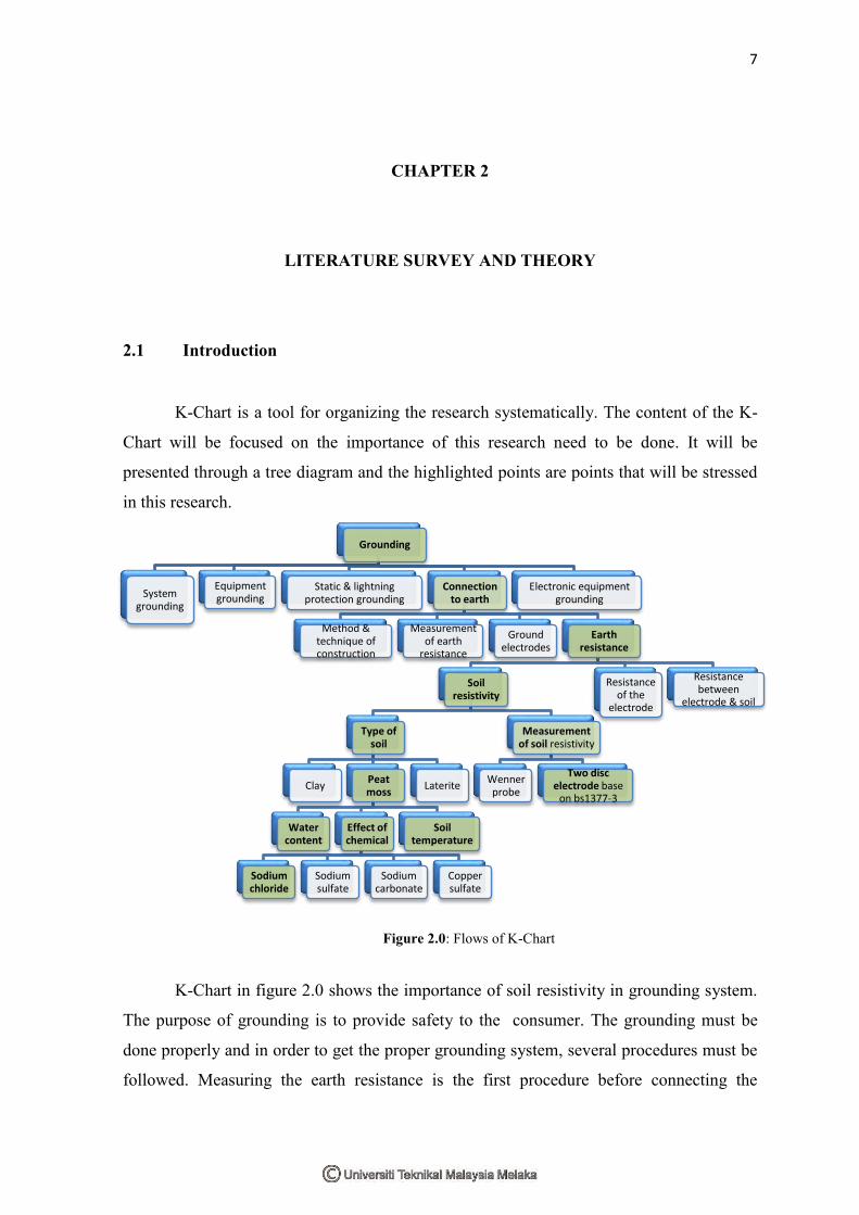
K-Chart is a tool for organizing the research systematically. The content of the K-
Chart will be focused on the importance of this research need to be done. It will be
presented through a tree diagram and the highlighted points are points that will be stressed
in this research.
Figure 2.0: Flows of K-Chart
K-Chart in figure 2.0 shows the importance of soil resistivity in grounding system.
The purpose of grounding is to provide safety to the consumer. The grounding must be
done properly and in order to get the proper grounding system, several procedures must be
followed. Measuring the earth resistance is the first procedure before connecting the
8
grounding system. Then, followed by the construction method used for temp the grounding
system and the application of the grounding system. Earth resistance is composed of three
elements which is the resistance of the electrode, the resistance between electrode and soil
and finally soil resistivity. Soil resistivity is the main topic for this research and more
details about that will be discussed.
2.2 Soil Resistivity
Practically, the layer structure of the soil and the depth of each layer will determine
the average resistivity of the soil. When it comes to grounding or earthing system, soil
resistivity is the most important factors that need to be concerned before attempting any
grounding system. This is because earth resistance is directly proportional to the earth
electrode that install into the earth.
According to Landviser.com, electrical soil resistivity was first measured at the end
of the 19th century. Whitney et al. (18970, Gardner (1898) and Briggs (1899) developed
relationship between soil resistivity with the factors of water content, temperature and salt
content [7]. Factors that include in the experiment is the factors that most affect the soil
resistivity.
Theoretically, resistance is a term to describe the behavior of opposing the electric
current flow when a voltage is applied across the two ends. In terms of soil resistivity,
sometimes resistivity is referred as specific resistance because resistivity is the resistance
between the opposite faces of cube of material with side dimension of one meter [8].
Normally, factors that have a big effect in soil resistivity are the type of soil,
moisturecontent, temperature and chemical composition. The resistivity of the soil may
decrease rapidly when the moisture of the soil is increase. However, after 20% of moisture,
the resistivity decrease is much less. Soil with moisture content greater than 40% is rarely
occurring. When the soil temperature is beyond the freezing point, soil resistivity will
become negilible. Soil resistivity also affected by the chemical content of the soil.
Normally, dissolved salt is a substance that oftenly give the variation to the soil resistivity
value[8].
9
2.3 Type of Soil
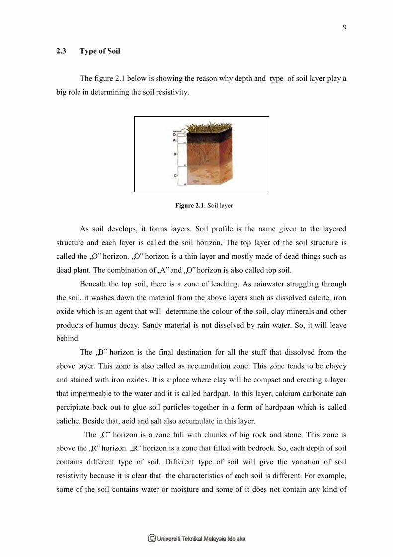
The figure 2.1 below is showing the reason why depth and type of soil layer play a
big role in determining the soil resistivity.
Figure 2.1: Soil layer
Figure 2.1: Soil layer
As soil develops, it forms layers. Soil profile is the name given to the layered
structure and each layer is called the soil horizon. The top layer of the soil structure is
called the „O‟ horizon. „O‟ horizon is a thin layer and mostly made of dead things such as
dead plant. The combination of „A‟ and „O‟ horizon is also called top soil.
Beneath the top soil, there is a zone of leaching. As rainwater struggling through
the soil, it washes down the material from the above layers such as dissolved calcite, iron
oxide which is an agent that will determine the colour of the soil, clay minerals and other
products of humus decay. Sandy material is not dissolved by rain water. So, it will leave
behind.
The „B‟ horizon is the final destination for all the stuff that dissolved from the
above layer. This zone is also called as accumulation zone. This zone tends to be clayey
and stained with iron oxides. It is a place where clay will be compact and creating a layer
that impermeable to the water and it is called hardpan. In this layer, calcium carbonate can
percipitate back out to glue soil particles together in a form of hardpaan which is called
caliche. Beside that, acid and salt also accumulate in this layer.
The „C‟ horizon is a zone full with chunks of big rock and stone. This zone is
above the „R‟ horizon. „R‟ horizon is a zone that filled with bedrock. So, each depth of soil
contains different type of soil. Different type of soil will give the variation of soil
resistivity because it is clear that the characteristics of each soil is different. For example,
some of the soil contains water or moisture and some of it does not contain any kind of
10
moisture. So, soil that contains more moisture normally posses low resistivity because
water or moisture is a good electrical conductor.
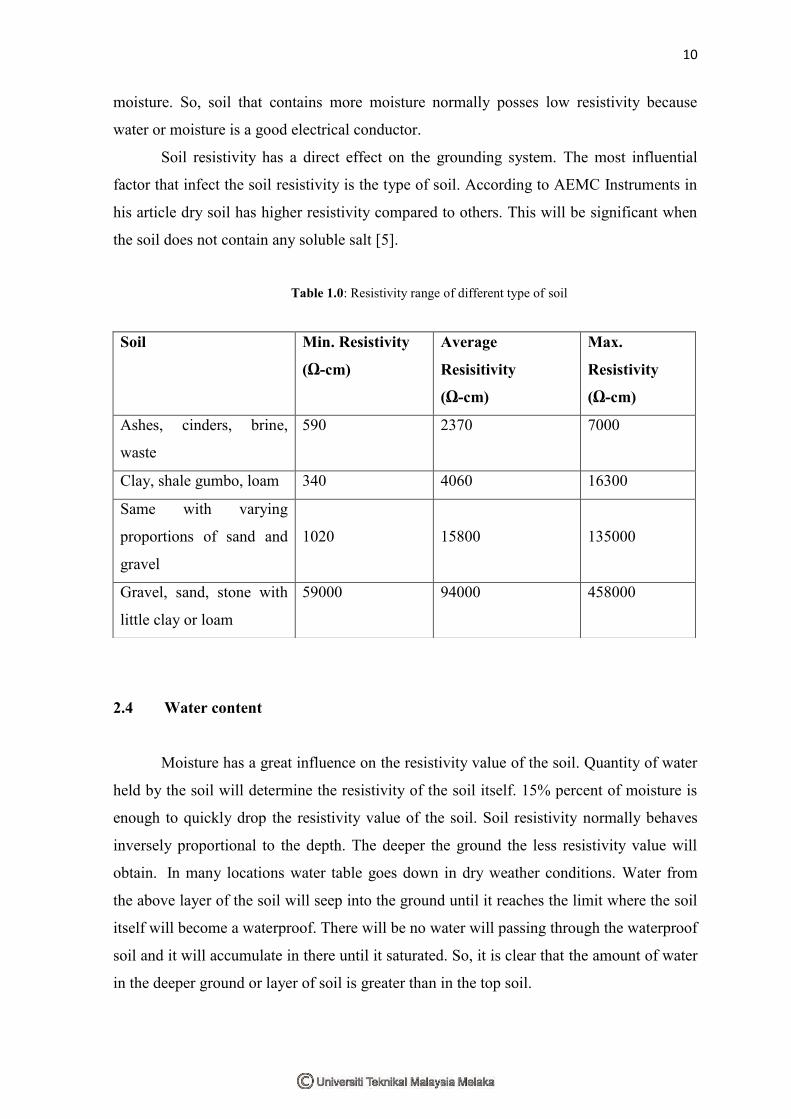
Soil resistivity has a direct effect on the grounding system. The most influential
factor that infect the soil resistivity is the type of soil. According to AEMC Instruments in
his article dry soil has higher resistivity compared to others. This will be significant when
the soil does not contain any soluble salt [5].
Table 1.0: Resistivity range of different type of soil
2.4 Water content
Moisture has a great influence on the resistivity value of the soil. Quantity of water
held by the soil will determine the resistivity of the soil itself. 15% percent of moisture is
enough to quickly drop the resistivity value of the soil. Soil resistivity normally behaves
inversely proportional to the depth. The deeper the ground the less resistivity value will
obtain. In many locations water table goes down in dry weather conditions. Water from
the above layer of the soil will seep into the ground until it reaches the limit where the soil
itself will become a waterproof. There will be no water will passing through the waterproof
soil and it will accumulate in there until it saturated. So, it is clear that the amount of water
in the deeper ground or layer of soil is greater than in the top soil.
Soil Min. Resistivity
(Ω-cm)
Average
Resisitivity
(Ω-cm)
Max.
Resistivity
(Ω-cm)
Ashes, cinders, brine,
waste
590 2370 7000
Clay, shale gumbo, loam 340 4060 16300
Same with varying
proportions of sand and
gravel
1020
15800
135000
Gravel, sand, stone with
little clay or loam
59000
94000 458000