intviewer indexing tutorial - int | 2d/3d data ... · intviewer indexing tutorial page 1 intviewer...
TRANSCRIPT
INTViewer Indexing Tutorial Page 1
INTViewer Indexing Tutorial This tutorial illustrates how to use the Indexing feature of the INTViewer. The INTViewer is capable of directly reading seismic file formats such as SEGY, SU, SEP, SVF, ProMAX, and JavaSeis. However, to fully take advantage of INTViewer, consider indexing multi-dimensional datasets. Formats that can be indexed are: SEGY, SU, and ProMAX (CIND). Other supported formats are either regular or have a built-in index. The purpose of indexing is to allow specification of access keys for the purpose of randomly accessing and selecting traces. For example, a seismic file containing gathers could be indexed using keys INLINE, XLINE and OFFSET. Once the gathers file has been indexed, it is possible to quickly access any gather, INLINE or XLINE for a specific OFFSET, or a set of gathers along an arbitrary path. The process of indexing does not produce a copy of the original seismic dataset; it only creates an index file and a master file. The index file will be approximately 1% of the original input file(s) size and contain a binary map of the trace locations optimized for fast access to specified keys. The master file is an XML file that links the original seismic dataset with the index file. It also contains statistics about the keys that were collected during the indexing operation. In this tutorial we will show how to index a seismic dataset stored in SEGY format using the indexing wizard. To follow this tutorial, select any of your seismic volume datasets that should be indexed: SEGY or SU for example. Indexing can also be done as a batch process. See section Additional Notes on Indexing at the end of this tutorial for information on how to run indexing in batch mode. Step 1 – Starting the Indexer Application To run the Indexer wizard, start the SeismicIndexer command located in the main folder of the INTViewer distribution, or run INTViewer and select Tools à Index Seismic. Note: on Linux/Unix/MacOS the installer may not always restore the execute permission for the command files. Make sure you change the permission of all “.sh” files in the main distribution directory using the following command: chmod +x *.sh
INTViewer Indexing Tutorial Page 2
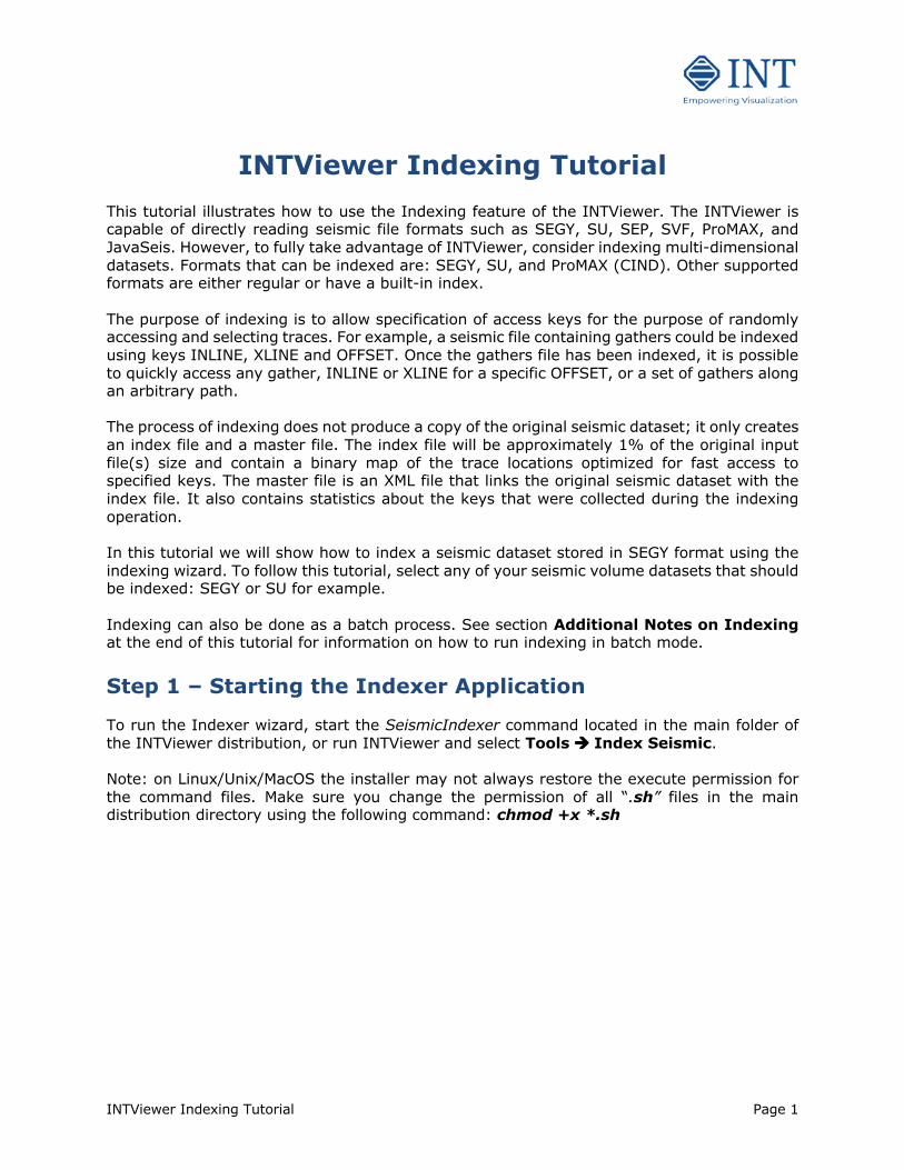
Figure 1: The Primary Indexing Panel
Figure 1 shows the primary indexing panel. Select the file(s) you want to index using the file chooser ( ) button. It is possible to input several files and have them indexed as one logical volume or have them indexed individually. Toggle the desired Multi-File Behavior button. Each input file is must be the same format. If you have chosen the Index Files Separately option this same descriptor file will be used for all input files. Once the seismic input file(s) and Multi-File Behavior are selected, click Next… to continue. If you have selected a SEGY file, the View EBCDIC button brings up a separate window containing the contents of the EBCDIC header for review. This area usually contains basic processing history notes, important trace header format information, or survey orientation details.
INTViewer Indexing Tutorial Page 3
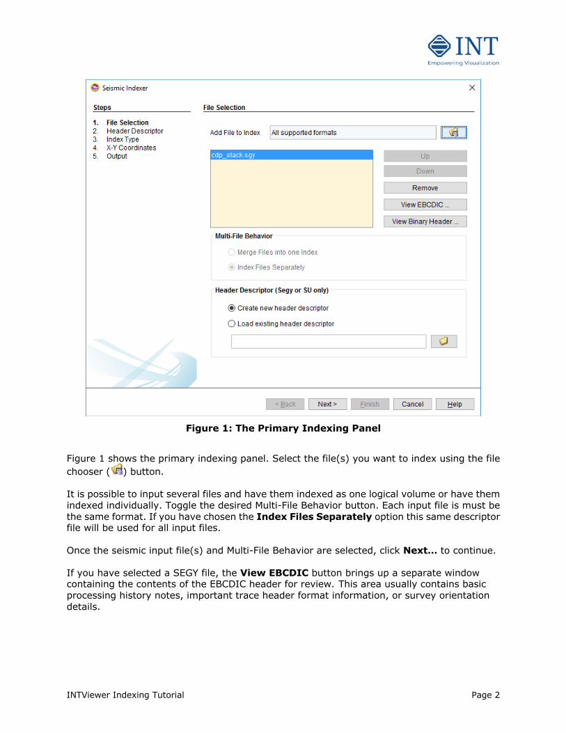
Figure 2: The SEGY EBCDIC Header (example)
Figure 2 shows an example EBCDIC Header from a SEGY file.
INTViewer Indexing Tutorial Page 4
Step 2 – Specifying or Creating a Descriptor File
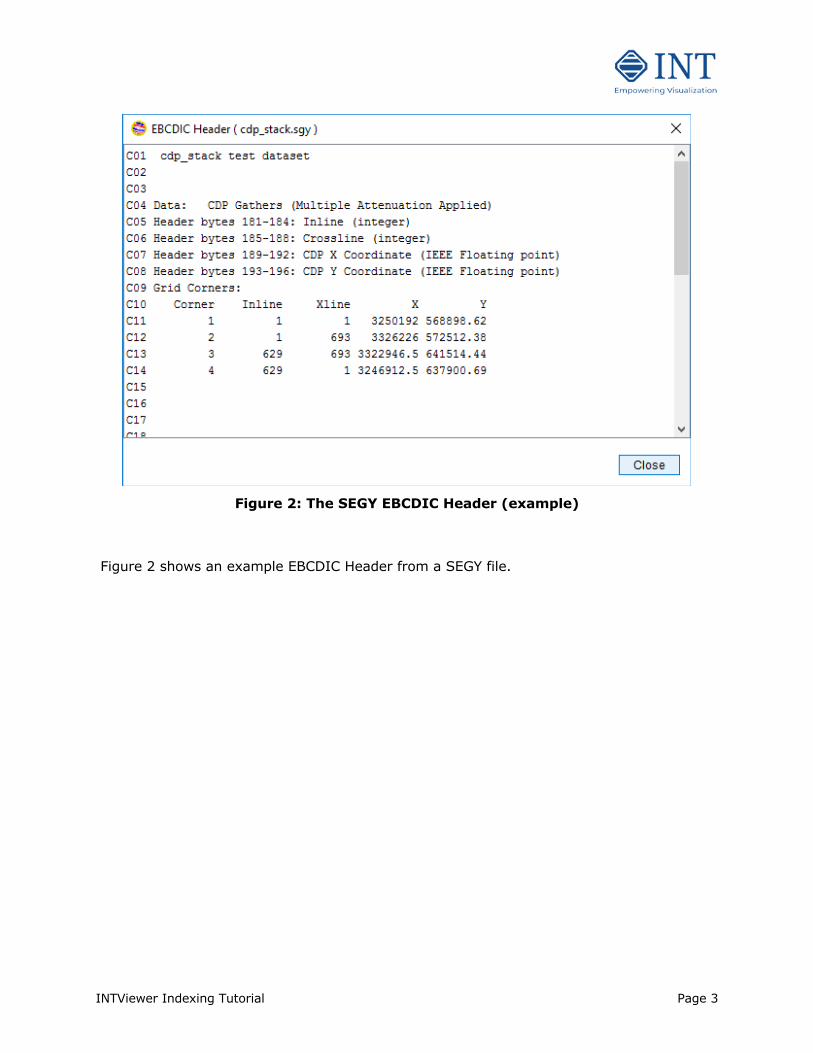
Figure 3: Select or build a Header Description Options
The next section, highlighted in Figure 3, has two choices for Header Descriptions. Click Next… to continue the indexing wizard if this is your first time. Otherwise, an existing Header Description can optionally be loaded by selecting the Load existing header descriptor, and
then clicking the file chooser ( ). The file chooser can be used to locate the descriptor file, or the path and name can be entered directly into the text field. To create a new header descriptor, select Create new header descriptor. Note that for ProMAX (*CIND) files no Descriptor file is needed: the header descriptor section shown in Figure 3 is not accessible and the dialog shown in Figure 4 is not displayed. Click Next…
INTViewer Indexing Tutorial Page 5
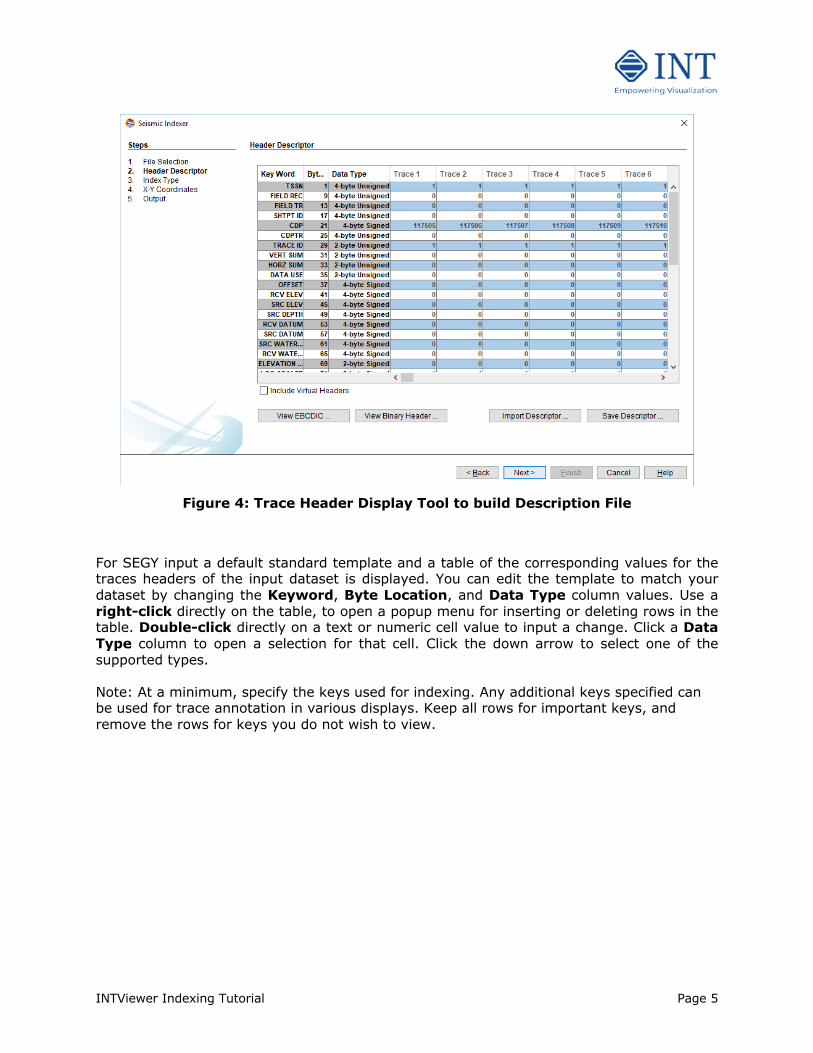
Figure 4: Trace Header Display Tool to build Description File
For SEGY input a default standard template and a table of the corresponding values for the traces headers of the input dataset is displayed. You can edit the template to match your dataset by changing the Keyword, Byte Location, and Data Type column values. Use a right-click directly on the table, to open a popup menu for inserting or deleting rows in the table. Double-click directly on a text or numeric cell value to input a change. Click a Data Type column to open a selection for that cell. Click the down arrow to select one of the supported types. Note: At a minimum, specify the keys used for indexing. Any additional keys specified can be used for trace annotation in various displays. Keep all rows for important keys, and remove the rows for keys you do not wish to view.
INTViewer Indexing Tutorial Page 6
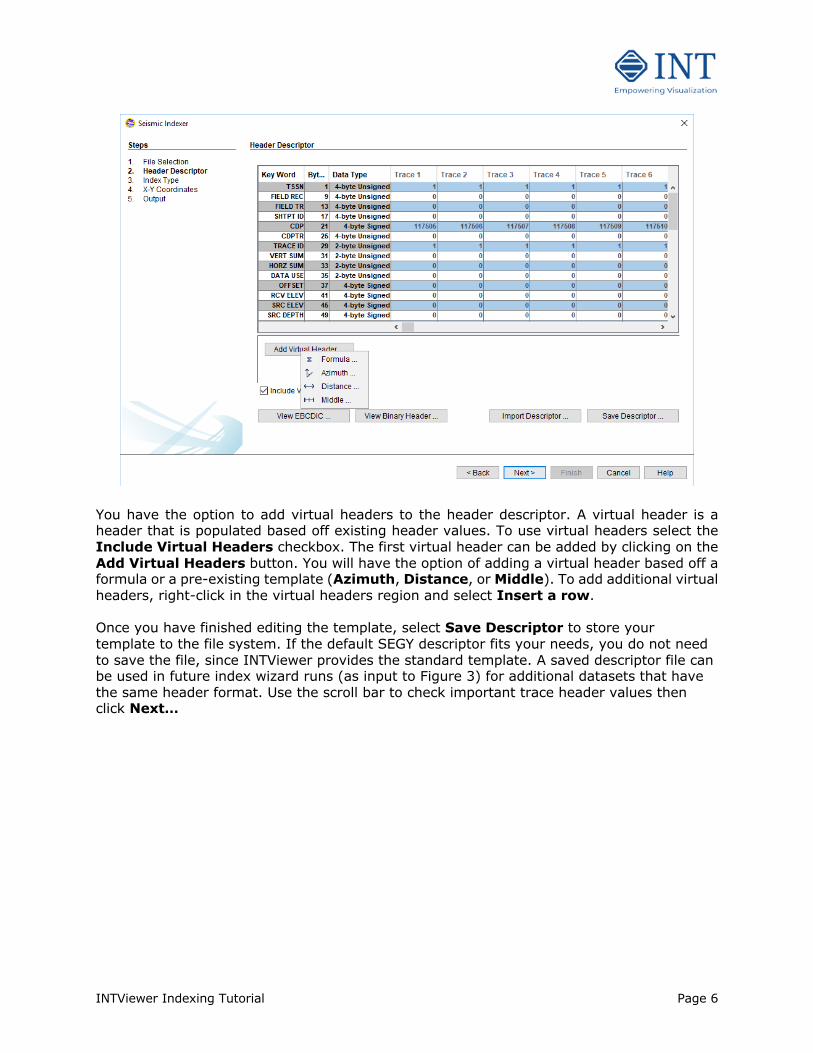
You have the option to add virtual headers to the header descriptor. A virtual header is a header that is populated based off existing header values. To use virtual headers select the Include Virtual Headers checkbox. The first virtual header can be added by clicking on the Add Virtual Headers button. You will have the option of adding a virtual header based off a formula or a pre-existing template (Azimuth, Distance, or Middle). To add additional virtual headers, right-click in the virtual headers region and select Insert a row. Once you have finished editing the template, select Save Descriptor to store your template to the file system. If the default SEGY descriptor fits your needs, you do not need to save the file, since INTViewer provides the standard template. A saved descriptor file can be used in future index wizard runs (as input to Figure 3) for additional datasets that have the same header format. Use the scroll bar to check important trace header values then click Next…
INTViewer Indexing Tutorial Page 7
Step 3 – Selecting the Index Keys.
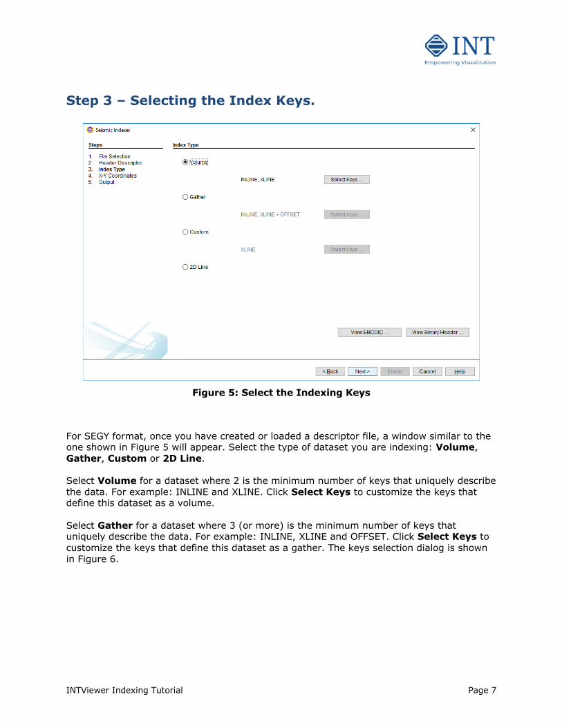
Figure 5: Select the Indexing Keys
For SEGY format, once you have created or loaded a descriptor file, a window similar to the one shown in Figure 5 will appear. Select the type of dataset you are indexing: Volume, Gather, Custom or 2D Line. Select Volume for a dataset where 2 is the minimum number of keys that uniquely describe the data. For example: INLINE and XLINE. Click Select Keys to customize the keys that define this dataset as a volume. Select Gather for a dataset where 3 (or more) is the minimum number of keys that uniquely describe the data. For example: INLINE, XLINE and OFFSET. Click Select Keys to customize the keys that define this dataset as a gather. The keys selection dialog is shown in Figure 6.
INTViewer Indexing Tutorial Page 8
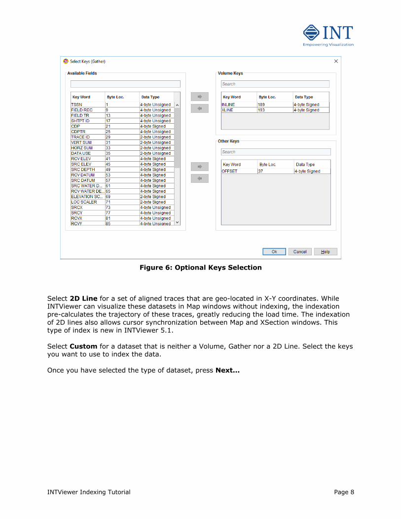
Figure 6: Optional Keys Selection
Select 2D Line for a set of aligned traces that are geo-located in X-Y coordinates. While INTViewer can visualize these datasets in Map windows without indexing, the indexation pre-calculates the trajectory of these traces, greatly reducing the load time. The indexation of 2D lines also allows cursor synchronization between Map and XSection windows. This type of index is new in INTViewer 5.1. Select Custom for a dataset that is neither a Volume, Gather nor a 2D Line. Select the keys you want to use to index the data. Once you have selected the type of dataset, press Next...
INTViewer Indexing Tutorial Page 9
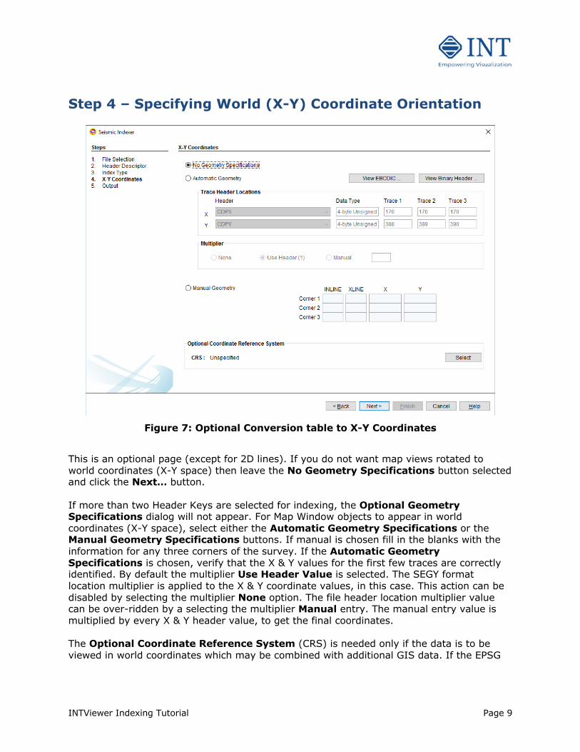
Step 4 – Specifying World (X-Y) Coordinate Orientation
Figure 7: Optional Conversion table to X-Y Coordinates
This is an optional page (except for 2D lines). If you do not want map views rotated to world coordinates (X-Y space) then leave the No Geometry Specifications button selected and click the Next… button. If more than two Header Keys are selected for indexing, the Optional Geometry Specifications dialog will not appear. For Map Window objects to appear in world coordinates (X-Y space), select either the Automatic Geometry Specifications or the Manual Geometry Specifications buttons. If manual is chosen fill in the blanks with the information for any three corners of the survey. If the Automatic Geometry Specifications is chosen, verify that the X & Y values for the first few traces are correctly identified. By default the multiplier Use Header Value is selected. The SEGY format location multiplier is applied to the X & Y coordinate values, in this case. This action can be disabled by selecting the multiplier None option. The file header location multiplier value can be over-ridden by a selecting the multiplier Manual entry. The manual entry value is multiplied by every X & Y header value, to get the final coordinates. The Optional Coordinate Reference System (CRS) is needed only if the data is to be viewed in world coordinates which may be combined with additional GIS data. If the EPSG
INTViewer Indexing Tutorial Page 10
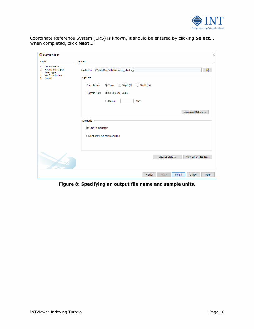
Coordinate Reference System (CRS) is known, it should be entered by clicking Select… When completed, click Next…
Figure 8: Specifying an output file name and sample units.
INTViewer Indexing Tutorial Page 11
Step 5 – Output File Name Specify the location of the output dataset new master file (see Figure 7). In our case, we just accept the default name. The master file extension is required to be “.xgy” for SEGY format, “.xsu” for SU format, and “.xpx” for ProMax format. This master file will be used as input when displaying in INTViewer. The path may be changed to any existing directory with write access. A binary index file, having the extension “.igx” will be written in the same directory as the master file. In the case of multi-file input indexed separately, the output file name will be the input file name with the extension changed as the format specification requires. If the data is in depth rather than time, specify the correct units in the Options block (Figure 8). The sample rate can also be specified manually. By default the Use Header Value option is selected to use information in the input data file. By clicking Manual the sample rate can be specified in depth or time units. Enter the desired depth (or time) digi value in the provided input field. Clicking on the Advanced Options button brings up a dialog rarely needed.
INTViewer Indexing Tutorial Page 12
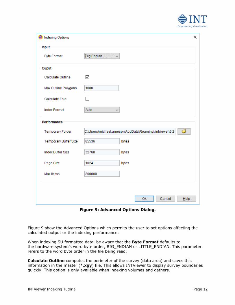
Figure 9: Advanced Options Dialog.
Figure 9 show the Advanced Options which permits the user to set options affecting the calculated output or the indexing performance. When indexing SU formatted data, be aware that the Byte Format defaults to the hardware system’s word byte order, BIG_ENDIAN or LITTLE_ENDIAN. This parameter refers to the word byte order in the file being read. Calculate Outline computes the perimeter of the survey (data area) and saves this information in the master (*.xgy) file. This allows INTViewer to display survey boundaries quickly. This option is only available when indexing volumes and gathers.
INTViewer Indexing Tutorial Page 13
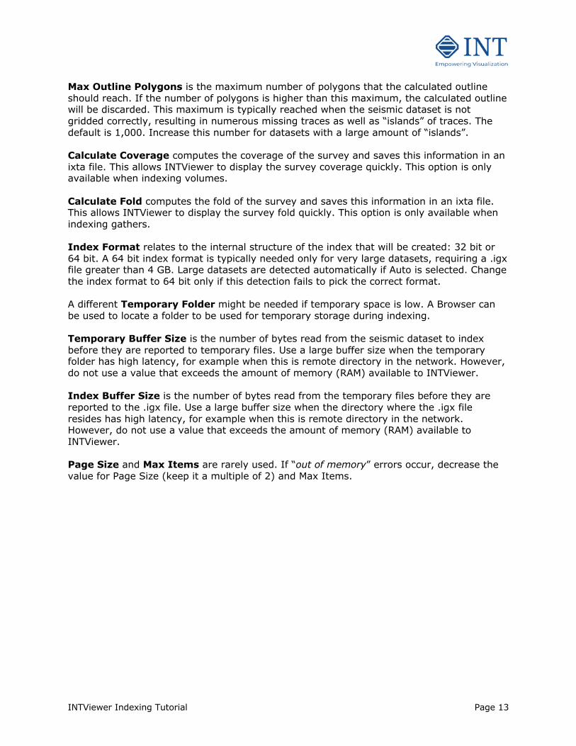
Max Outline Polygons is the maximum number of polygons that the calculated outline should reach. If the number of polygons is higher than this maximum, the calculated outline will be discarded. This maximum is typically reached when the seismic dataset is not gridded correctly, resulting in numerous missing traces as well as “islands” of traces. The default is 1,000. Increase this number for datasets with a large amount of “islands”. Calculate Coverage computes the coverage of the survey and saves this information in an ixta file. This allows INTViewer to display the survey coverage quickly. This option is only available when indexing volumes. Calculate Fold computes the fold of the survey and saves this information in an ixta file. This allows INTViewer to display the survey fold quickly. This option is only available when indexing gathers. Index Format relates to the internal structure of the index that will be created: 32 bit or 64 bit. A 64 bit index format is typically needed only for very large datasets, requiring a .igx file greater than 4 GB. Large datasets are detected automatically if Auto is selected. Change the index format to 64 bit only if this detection fails to pick the correct format. A different Temporary Folder might be needed if temporary space is low. A Browser can be used to locate a folder to be used for temporary storage during indexing. Temporary Buffer Size is the number of bytes read from the seismic dataset to index before they are reported to temporary files. Use a large buffer size when the temporary folder has high latency, for example when this is remote directory in the network. However, do not use a value that exceeds the amount of memory (RAM) available to INTViewer. Index Buffer Size is the number of bytes read from the temporary files before they are reported to the .igx file. Use a large buffer size when the directory where the .igx file resides has high latency, for example when this is remote directory in the network. However, do not use a value that exceeds the amount of memory (RAM) available to INTViewer. Page Size and Max Items are rarely used. If “out of memory” errors occur, decrease the value for Page Size (keep it a multiple of 2) and Max Items.
INTViewer Indexing Tutorial Page 14
Step 6 – Indexing
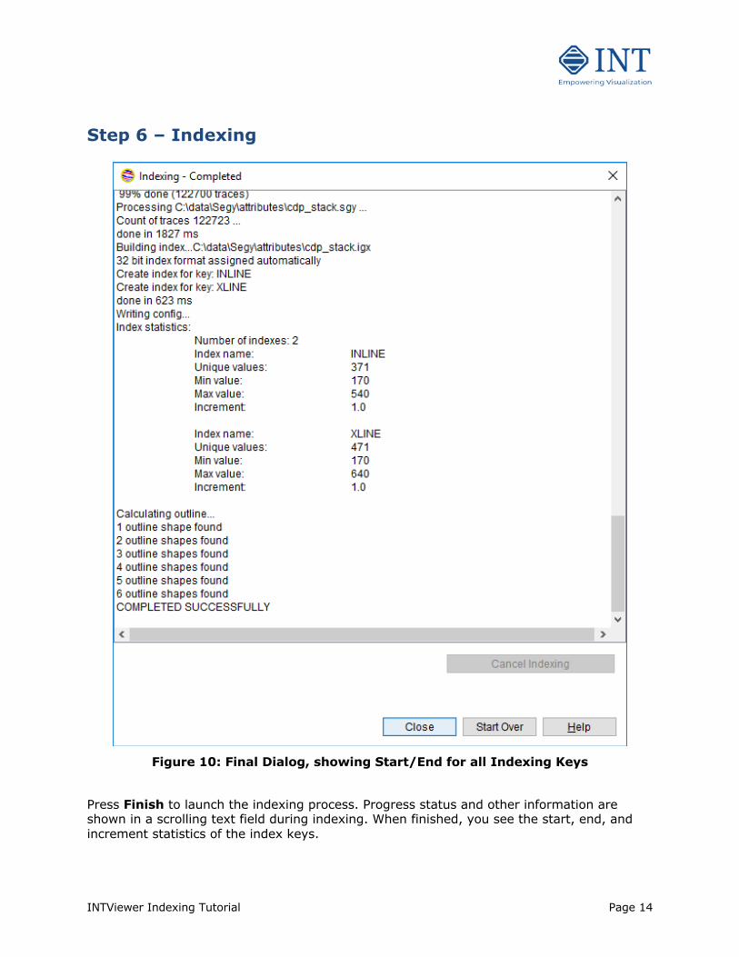
Figure 10: Final Dialog, showing Start/End for all Indexing Keys
Press Finish to launch the indexing process. Progress status and other information are shown in a scrolling text field during indexing. When finished, you see the start, end, and increment statistics of the index keys.
INTViewer Indexing Tutorial Page 15
An “Indexing is Done” notification is presented.
Figure 11: Index Wizard Completion Notification
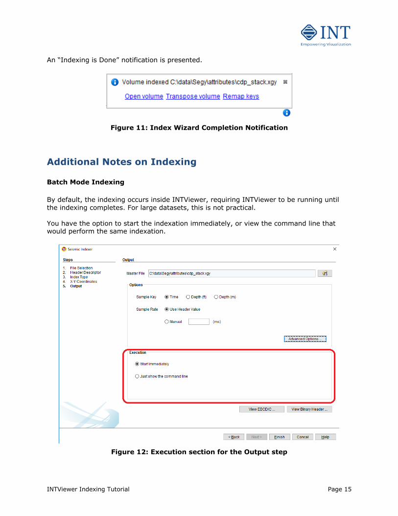
Additional Notes on Indexing Batch Mode Indexing By default, the indexing occurs inside INTViewer, requiring INTViewer to be running until the indexing completes. For large datasets, this is not practical. You have the option to start the indexation immediately, or view the command line that would perform the same indexation.
Figure 12: Execution section for the Output step
INTViewer Indexing Tutorial Page 16
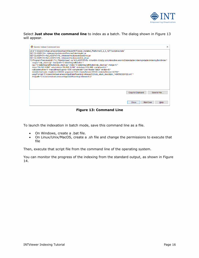
Select Just show the command line to index as a batch. The dialog shown in Figure 13 will appear.
Figure 13: Command Line
To launch the indexation in batch mode, save this command line as a file.
• On Windows, create a .bat file. • On Linux/Unix/MacOS, create a .sh file and change the permissions to execute that
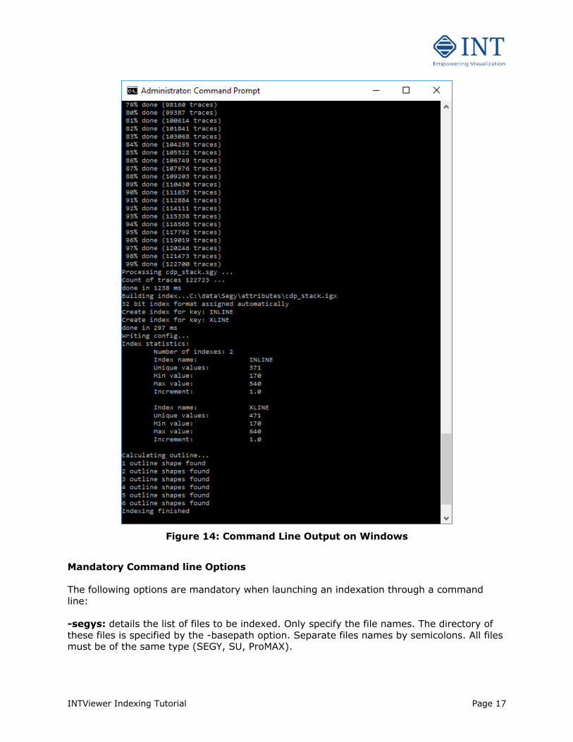
file Then, execute that script file from the command line of the operating system. You can monitor the progress of the indexing from the standard output, as shown in Figure 14.
INTViewer Indexing Tutorial Page 17
Figure 14: Command Line Output on Windows
Mandatory Command line Options The following options are mandatory when launching an indexation through a command line: -segys: details the list of files to be indexed. Only specify the file names. The directory of these files is specified by the -basepath option. Separate files names by semicolons. All files must be of the same type (SEGY, SU, ProMAX).

INTViewer Indexing Tutorial Page 18
-basepath: full path of the folder where the files to index are stored. -xgy: full path of the index file to create. This file has the .xgy extension for SEGY files, .xsu for SU files and .xpx for ProMAX files. If no parent directory is specified, the current execution directory will be used. -index: full path of the binary index file to create. This file typically has the .igx extension. If no parent directory is specified, the current execution directory will be used. The .igx file is often stored in the same directory as the .xgy file, but this is not required. -segyFormat: full path of the format descriptor file. This file specifies the name and offset of each field. This option is mandatory only for SEGY and SU files. Use the NONE keyword for ProMAX files. -keys: name of the keys to index, separated by semicolons. A typical value is “INLINE;XLINE” for volumes, “INLINE;XLINE;OFFSET” for gathers, “CDPX;CDPY” for 2D lines. These key names must match field names in the format descriptor. Optional Command Line Options -merge: indicates whether each file should be indexed separately or whether all files should be indexed as one dataset. Use Y to create one index file, N for several index files. This option only applies when several files are specified in the -segys option. If the -merge option is not specified, the files will be indexed separately. -tmppath: full path of the directory where temporary files will be created. If this option is not specified, the default Java temporary directory will be used. -sampleunit: indicates whether to index files as time (s), depth in feet (ft) or depth in meters (m). Only the symbols s, ft and m are accepted. If this option is not specified, the files will be indexed in time. -samplerate: indicates the sample rate of the indexed datasets. This sample rate is expressed in milliseconds. If this option is not specified, the sample rate will be detected from header values. -indextype: defines the type of dataset being indexed: VOLUME, GATHER, 2DLINE or CUSTOM. If this option is not specified, the type will be CUSTOM. -calculateoutline: indicates whether to calculate the outline during indexing. Use Y to trigger an outline calculation, N for no outline calculation. If this option is not specified, no outline will be calculated. This option is typically used for volumes and gathers -maxoutlinepolygons: indicates the maximum number of polygons to calculate. When this maximum is reached, the calculated outline is discarded. If this option is not specified, the maximum will be 1000. -volumekeys: name of the keys that define the files to index as a volume. Typical values are “INLINE;XLINE”. These key names must match key names in the -keys option. If the -
INTViewer Indexing Tutorial Page 19
volumekeys option is not specified, no volume keys will be recorded. This option is typically used with VOLUME and GATHER index types. -xykeys: name of the fields that define the X-Y coordinates/position of each trace. A typical value is “CDPX;CDPY”. These field names must match field names in the format descriptor. If this option is not specified, no position fields will be recorded. -xymultiplier: name of the field whose value must be used to adjust the X-Y coordinates. Use this option only if the -xykeys option is specified. A typical value is “LOC SCALER” for SEGY files. This field name must match a field name in the format descriptor. If the multiplier value found is positive (ex: 100), then the X and Y coordinates found in each trace will be multiplied by that number. If the multiplier value found is negative (ex: -100), then the X and Y values will be divided by the absolute value of that number. If the -xymultiplier option is not specified, no adjustment will occur. -calculate2dline: indicates whether to calculate the trajectory of traces during indexing. Use Y to trigger a trajectory calculation, N for no trajectory calculation. If the -calculate2dline option is not specified, no trajectory will be calculated. This option is typically used along the -indextype option when that type is 2DLINE. -max2dlinepoints: indicates the maximum number of trajectory points to calculate. If the –max2dlinepoints option is not specified, 1000 will be used. If the number of traces found is greater than this number, a Douglas-Peucker algorithm will be used to simplify the trajectory. This option should be used only when the -calculate2dline option is enabled. -calculatefold: indicates whether to calculate the number of traces for each INLINE-XLINE pair during indexing. The output of that calculation will be a file with the extension .ixta. Use Y to trigger a fold calculation, N for no fold calculation. If this option is not specified, no fold will be calculated. The -calculatefold option is typically used along the -indextype option when that type is GATHER and should be used only when the -volumekeys option is used as well. -xygeometry: indicates the XLINE to X-Y corner point geometry to record along the file to index. An example of value is [[170 170 3267878.16 588349.47][170 640 3319519.60 590804.09][540.0 170.0 3265946.22 629003.42]]. In this example, INLINE-XLINE coordinates (170, 170) will be transformed to X-Y coordinates (3267878.16, 588349.47). If the -xygeometry option is not specified, no geometry will be recorded. -calculatexygeometry: indicates whether to calculate the INLINE-XLINE to X-Y corner point geometry automatically during indexing. The -xykeys option must be specified in that case. If the -calculatexygeometry option is not specified, no geometry will be calculated. -epsgcode: indicates the coordinate reference system of the dataset. This code corresponds to the code of that coordinate reference system in the EPSG database. For example: 32040 for “NAD 27 / Texas South Central”. If the code of the transformation to WGS84 is known, specify that code after a column character. Example 32040:1234 for a transformation to WGS84 with the code 1234. Use the “unknown” keyword (ex: 32040:unknown) to indicate that the transformation to WGS84 is not known. If the -epsgcode option is not specified, no coordinate reference system will be recorded.
INTViewer Indexing Tutorial Page 20
-endian: Word byte order of the file being read: Big Endian (B) or Little Endian (L). Only the B and L symbols are accepted. If the -endian option is not specified, the hardware system’s word byte order will be used. This option is typically used when indexing SU files. -indexformat: Internal byte representation in the .igx file . Only the auto, 32bit and 64bit values are accepted. If the –indexformat option is not specified, auto will be used. -tmpbuffersize: Buffer size prior to writing to temporary files. If the – tmpbuffersize option is not specified, 65536 will be used. -indexbuffersize: Buffer size prior to writing to the .igx file. If the – indexbuffersize option is not specified, 32768 will be used. -maxitems: a number between 1000 and 1,000,000. If this option is not specified, 200,000 will be used. Increase this value only if out of memory errors occur during indexing. -pagesize: a power of 2. If this option is not specified, 1024 will be used. Decrease this value only if out of memory errors occur during indexing. Indexing very large files It is possible to index very large files (1 Terabyte or more) however keep in mind that indexing such files could take several hours. In such cases, make sure you have efficient access to those files (avoid slow access over a busy network). You may also want to specify where the temporary work files are placed, this option is available under “Advanced Options” on the Output page (see Figures 8 and 9). Contact INTViewer support ([email protected]) if you have questions or problems with indexing.