introduction to multiwavelength optical networks fileintroduction to multiwavelength optical...
TRANSCRIPT
L11 - 1P. Raatikainen Switching Technology / 2005
Introduction to MultiwavelengthOptical Networks
Switching Technology S38.165http://www.netlab.hut.fi/opetus/s38165
Source: Stern-Bala (1999), Multiwavelength Optical Ne tworks
L11 - 2P. Raatikainen Switching Technology / 2005
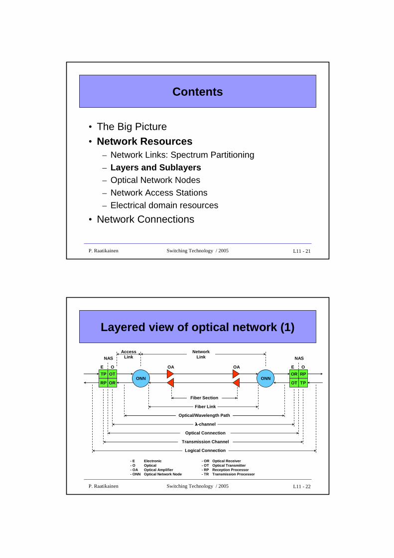
Contents
• The Big Picture• Network Resources• Network Connections
L11 - 3P. Raatikainen Switching Technology / 2005
Optical network
• Why ?– technology push, but no significant demand pull yet– evolving bandwidth hungry applications
– optical transport already in the trunk network
• Why not yet ?– optical last mile (a.k.a. the first mile) solutions still relatively primitive
– still too expensive– administrative, political, etc. reasons
=> “The information superhighway is still a dirt road; more accurately, it is a set of isolated multilane highways with cow paths for entrance.”
• However, development getting pace
L11 - 4P. Raatikainen Switching Technology / 2005
Optical network (cont.)
• An optical network is defined to be a telecommunications network – with transmission links that are optical fibers, and – with an architecture designed to exploit the unique features of fibers
• The term optical network (as used here) – does not necessarily imply a purely optical network,
– but it does imply something more than a set of fibers terminated by electronic devices
• The “glue” that holds the purely optical network together consists of – optical network nodes (ONN) connecting the fibers within the network– network access stations (NAS) interfacing user terminals and other non-
optical end-systems to the optical network
L11 - 5P. Raatikainen Switching Technology / 2005
Optical network (cont.)
ONN (Optical Network Node)• provides switching and routing functions to control optical signal paths,
configuring them to create required connections
NAS (Network Access Station)• provides termination point for optical paths within the optical network layer
Basic types of optical networks• transparent (purely optical) networks
– Static network = broadcast-and-select network– Wavelength Routed Network (WRN)
– Linear Lightwave Network (LLN) = waveband routed network
• hybrid optical network = layered optical network
– Logically Routed Network (LRN)
L11 - 6P. Raatikainen Switching Technology / 2005
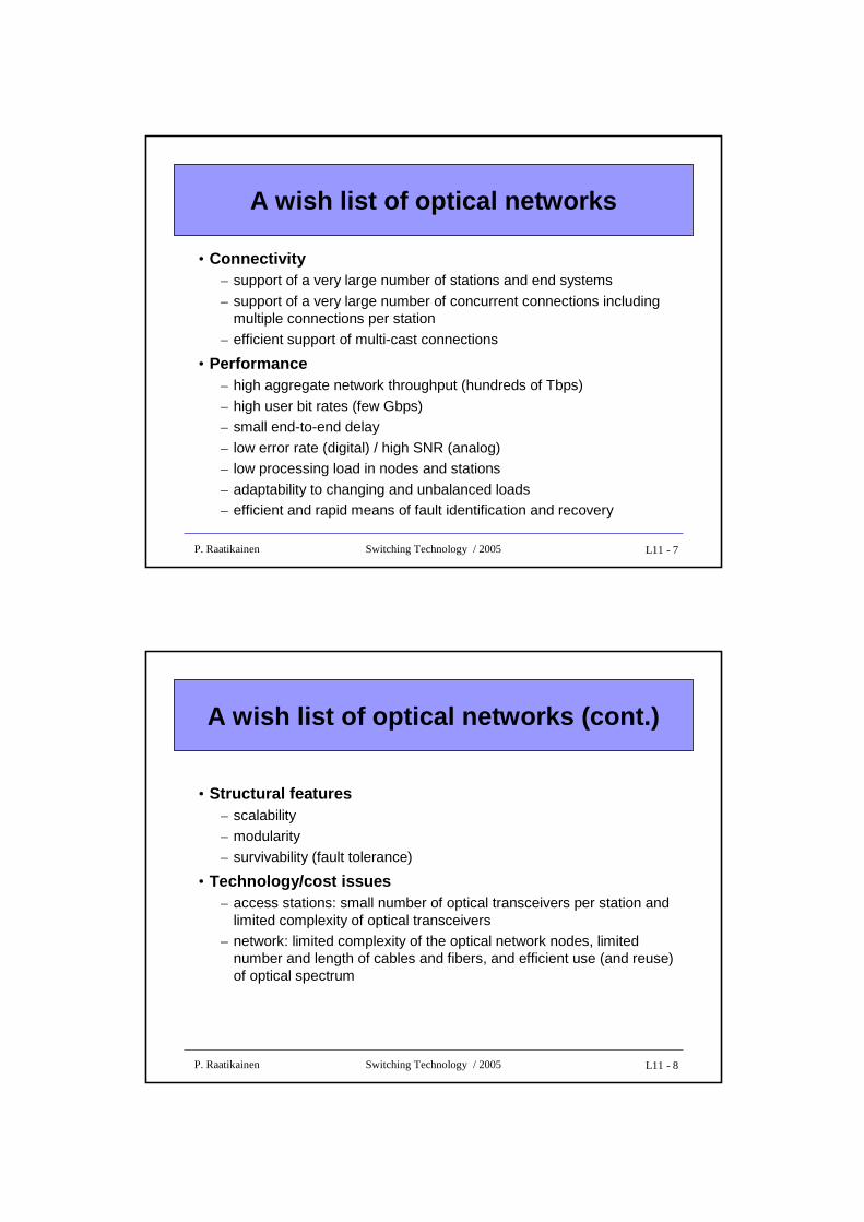
Physical picture of the network
NAS
NAS
NAS
NAS
NAS
NAS
Work-station
Multimediaterminal
Super-computer
Multimediaterminal
LAN
ONN
LANLAN
ATM
ATM
ATM
ATM
ONN - Optical Network NodeNAS - Network Access StationLAN - Local Area Network
L11 - 7P. Raatikainen Switching Technology / 2005
A wish list of optical networks
• Connectivity– support of a very large number of stations and end systems
– support of a very large number of concurrent connections including multiple connections per station
– efficient support of multi-cast connections
• Performance– high aggregate network throughput (hundreds of Tbps)
– high user bit rates (few Gbps)– small end-to-end delay
– low error rate (digital) / high SNR (analog)– low processing load in nodes and stations
– adaptability to changing and unbalanced loads– efficient and rapid means of fault identification and recovery
L11 - 8P. Raatikainen Switching Technology / 2005
A wish list of optical networks (cont.)
• Structural features– scalability– modularity
– survivability (fault tolerance)
• Technology/cost issues– access stations: small number of optical transceivers per station and
limited complexity of optical transceivers– network: limited complexity of the optical network nodes, limited
number and length of cables and fibers, and efficient use (and reuse) of optical spectrum
L11 - 9P. Raatikainen Switching Technology / 2005
Optics vs. electronics
Optical domain• photonic technology is well suited to certain simple (linear) signal-routing
and switching functions
• static photonic devices offer
• optical power combining, slitting and filtering
• wavelength multiplexing, demultiplexing and routing
• channelization needed to make efficient use of the enormous bandwidth of the fiber
• by wavelength division multiplexing (WDM)• many signals operating on different wavelengths share each fiber
=> optics is fast but dumb=> connectivity bottleneck
L11 - 10P. Raatikainen Switching Technology / 2005
Optics vs. electronics (cont.)
Electrical domain• electronics is needed to perform more complex (nonlinear) functions
• signal detection, regeneration and buffering
• logic functions (e.g. reading and writing packet headers)
• however, these complex functions limit the throughput
• electronics also gives a possibility to include in-band control information (e.g. in packet headers)
• enabling a high degree of virtual connectivity
• easier to control
=> electronics is slow but smart=> electronic bottleneck
L11 - 11P. Raatikainen Switching Technology / 2005
Optics and electronics
Hybrid approach:• a multiwavelength purely optical network as a physical foundation
• one or more logical networks (LN) superimposed on the physical layer, each– designed to serve some subset of user requirements and
– implemented as an electronic overlay
• an electronic switching equipment in the logical layer acts as a middleman– taking the high-bandwidth transparent channels provided by the physical layer and
organizing them into an acceptable and cost-effective form
Why hybrid approach ?• purely optical wavelength selective switches offer huge aggregate throughput
of few connections• electronic packet switches offer large number of relatively low bit rate virtual
connections• hybrid approach exploits the unique capabilities of optical and electronic
switching while circumventing their limitations
L11 - 12P. Raatikainen Switching Technology / 2005
Example LAN interconnection
• Consider a future WAN serving as a backbone that interconnects a large number of high-speed LANs (say 10,000), accessing the WAN through LAN gateways (with aggregate traffic of tens of Tbps)
• Purely optical approach– each NAS connects its LAN to the other LANs through individual optical
connections ⇒ 9 999 connections per NAS– this is far too much for current optical technology
• Purely electronic approach
– electronics easily supports required connectivity via virtual connections
– however, the electronic processing bottleneck in the core network does not allow such traffic
• Hybrid approach: both objectives achieved, since – LN composed of ATM switches provides the necessary connectivity– optical backbone at the physical layer supports the required throughput
L11 - 13P. Raatikainen Switching Technology / 2005
Contents
• The Big Picture• Network Resources
– Network Links: Spectrum Partitioning– Layers and Sublayers– Optical Network Nodes
– Network Access Stations
– Electrical domain resources
• Network Connections
L11 - 14P. Raatikainen Switching Technology / 2005
Network links
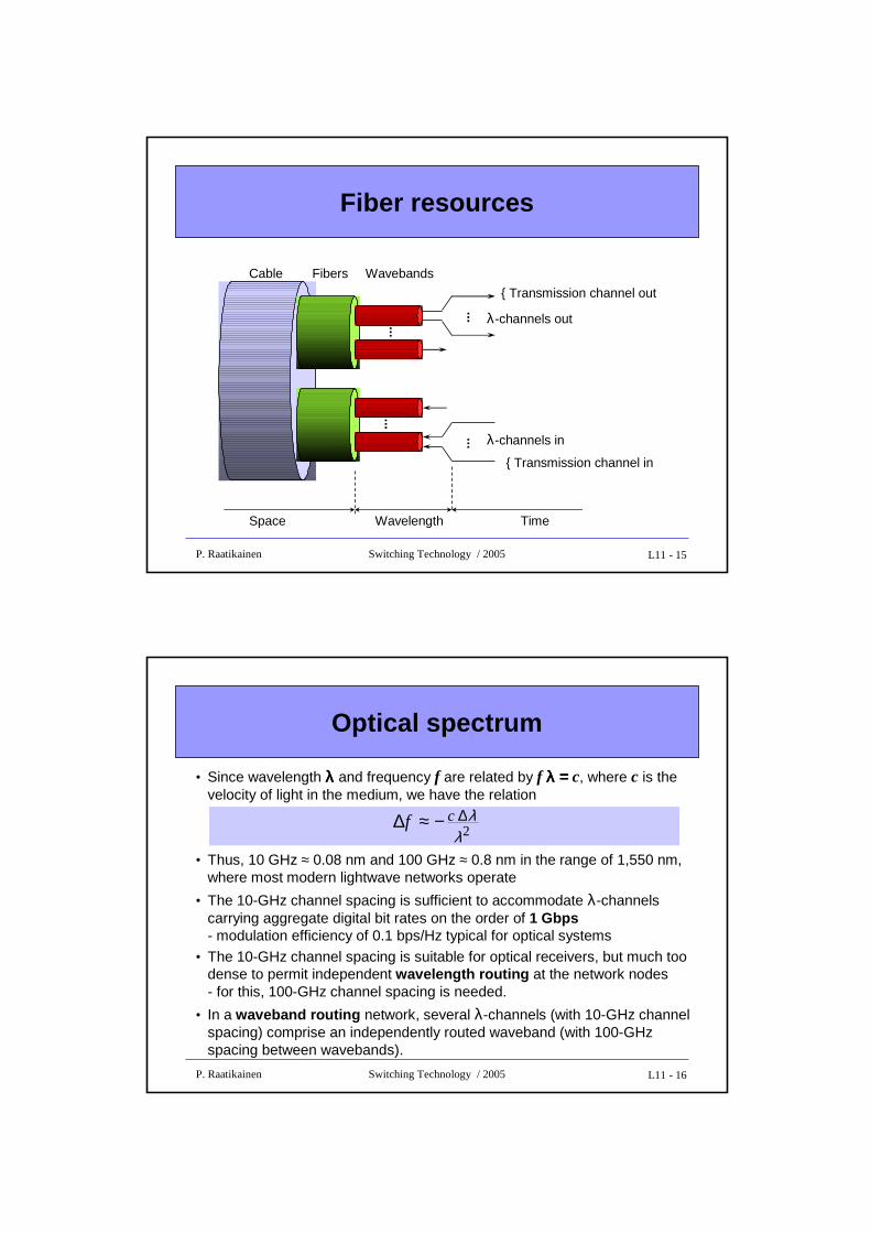
A large number of concurrent connections can be supported on each network link through successive levels of multiplexing
• Space division multiplexing in the fiber layer:– a cable consists of several (sometimes more than 100) fibers, which are
used as bi-directional pairs
• Wavelength division multiplexing (WDM) in the optical layer:
– a fiber carries connections on many distinct wavelengths (λ-channels)– assigned wavelengths must be spaced sufficiently apart to keep
neighboring signal spectra from overlapping (to avoid interference)
• Time division multiplexing (TDM) in the transmission channel sublayer:
– a λ-channel is divided (in time) into frames and time-slots– each time-slot in a frame corresponds to a transmission channel, which
is capable of carrying a logical connection
– location of a time-slot in a frame identifies a transmission channel
L11 - 15P. Raatikainen Switching Technology / 2005
Fiber resources
{ Transmission channel out
λ-channels out
......
......
Cable Fibers Wavebands
{ Transmission channel in
λ-channels in
Space Wavelength Time
L11 - 16P. Raatikainen Switching Technology / 2005
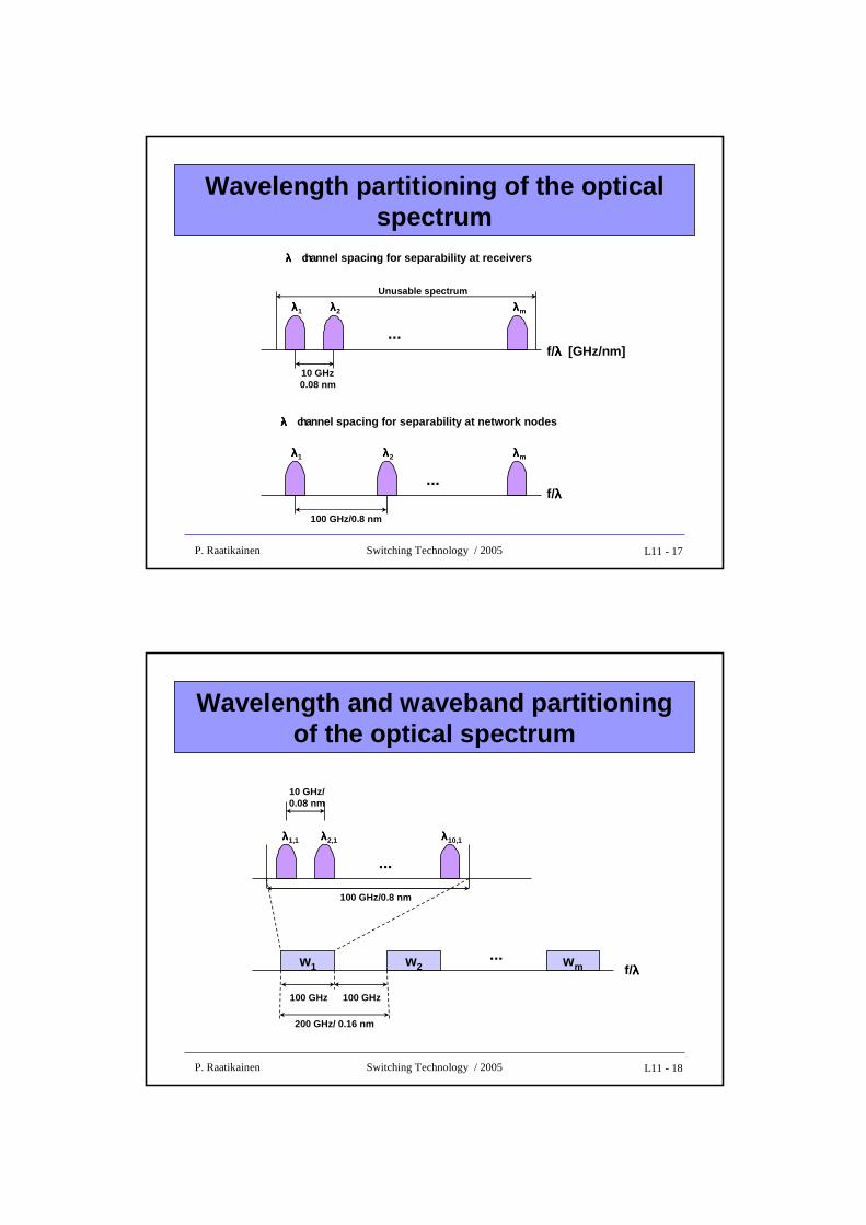
Optical spectrum
• Since wavelength λλλλ and frequency f are related by f λ = λ = λ = λ = c, where c is the velocity of light in the medium, we have the relation
• Thus, 10 GHz ≈ 0.08 nm and 100 GHz ≈ 0.8 nm in the range of 1,550 nm, where most modern lightwave networks operate
• The 10-GHz channel spacing is sufficient to accommodate λ-channels carrying aggregate digital bit rates on the order of 1 Gbps- modulation efficiency of 0.1 bps/Hz typical for optical systems
• The 10-GHz channel spacing is suitable for optical receivers, but much too dense to permit independent wavelength routing at the network nodes - for this, 100-GHz channel spacing is needed.
• In a waveband routing network, several λ-channels (with 10-GHz channel spacing) comprise an independently routed waveband (with 100-GHz spacing between wavebands).
2
λλ∆−≈∆ cf
L11 - 17P. Raatikainen Switching Technology / 2005
Wavelength partitioning of the optical spectrum
λλλλ- channel spacing for separability at receivers
λλλλ1 λλλλ2 λλλλm
...
10 GHz0.08 nm
Unusable spectrum
f/λλλλ [GHz/nm]
λλλλ- channel spacing for separability at network nodes
λλλλ1 λλλλ2 λλλλm
...
100 GHz/0.8 nm
f/λλλλ
L11 - 18P. Raatikainen Switching Technology / 2005
Wavelength and waveband partitioning of the optical spectrum
λλλλ1,1 λλλλ2,1 λλλλ10,1
...
10 GHz/0.08 nm
100 GHz/0.8 nm
w1 wmw2
100 GHz
...f/λλλλ
100 GHz
200 GHz/ 0.16 nm
L11 - 19P. Raatikainen Switching Technology / 2005
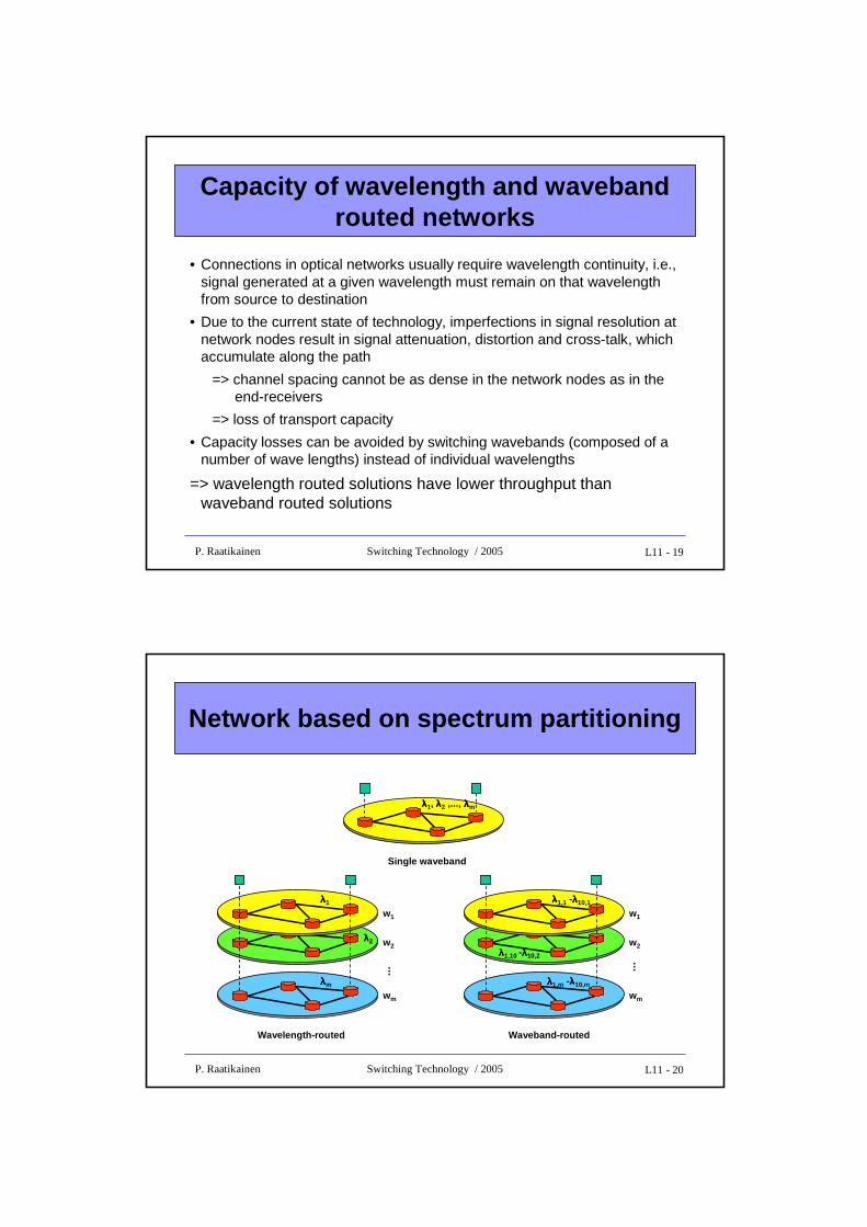
Capacity of wavelength and waveband routed networks
• Connections in optical networks usually require wavelength continuity, i.e., signal generated at a given wavelength must remain on that wavelength from source to destination
• Due to the current state of technology, imperfections in signal resolution at network nodes result in signal attenuation, distortion and cross-talk, which accumulate along the path
=> channel spacing cannot be as dense in the network nodes as in the end-receivers
=> loss of transport capacity
• Capacity losses can be avoided by switching wavebands (composed of a number of wave lengths) instead of individual wavelengths
=> wavelength routed solutions have lower throughput than waveband routed solutions
L11 - 20P. Raatikainen Switching Technology / 2005
Network based on spectrum partitioning
λλλλ1, λλλλ2 ,..., λλλλm
Single waveband
λλλλm
λλλλ2
λλλλ1
w1
w2
wm
Wavelength-routed
...
λλλλ1,m -λλλλ10,m
λλλλ1,10 -λλλλ10,2
λλλλ1,1 -λλλλ10,1
w1
w2
wm
Waveband-routed
...
L11 - 21P. Raatikainen Switching Technology / 2005
Contents
• The Big Picture• Network Resources
– Network Links: Spectrum Partitioning
– Layers and Sublayers– Optical Network Nodes
– Network Access Stations– Electrical domain resources
• Network Connections
L11 - 22P. Raatikainen Switching Technology / 2005
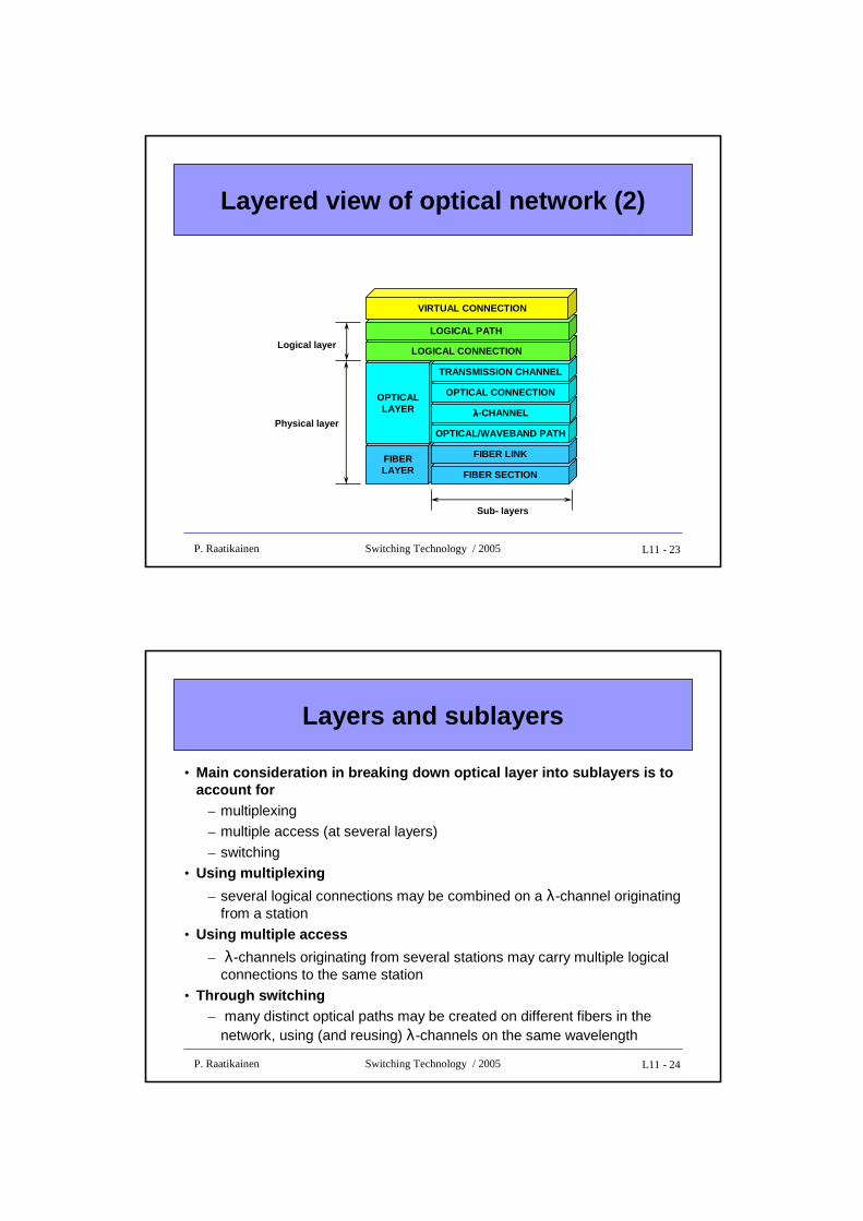
Layered view of optical network (1)
NAS NAS
TP
RP
OT
ORONN
OA OA
ONNTP
RP
OT
OR
E O E O
Fiber Section
Fiber Link
Optical/Wavelength Path
λλλλ-channel
Transmission Channel
Logical Connection
Optical Connection
Network Link
AccessLink
- E Electronic - OR Optical Receiver- O Optical - OT Optical Transmitter- OA Optical Amplifier - RP Reception Processor- ONN Optical Network Node - TR Transmission Processor
L11 - 23P. Raatikainen Switching Technology / 2005
Layered view of optical network (2)
FIBERLAYER
OPTICALLAYER
FIBER SECTION
FIBER LINK
OPTICAL/WAVEBAND PATH
λλλλ-CHANNEL
OPTICAL CONNECTION
TRANSMISSION CHANNEL
LOGICAL CONNECTION
LOGICAL PATH
VIRTUAL CONNECTION
Logical layer
Physical layer
Sub- layers
L11 - 24P. Raatikainen Switching Technology / 2005
Layers and sublayers
• Main consideration in breaking down optical layer i nto sublayers is to account for
– multiplexing– multiple access (at several layers)
– switching• Using multiplexing
– several logical connections may be combined on a λ-channel originating from a station
• Using multiple access
– λ-channels originating from several stations may carry multiple logical connections to the same station
• Through switching– many distinct optical paths may be created on different fibers in the
network, using (and reusing) λ-channels on the same wavelength
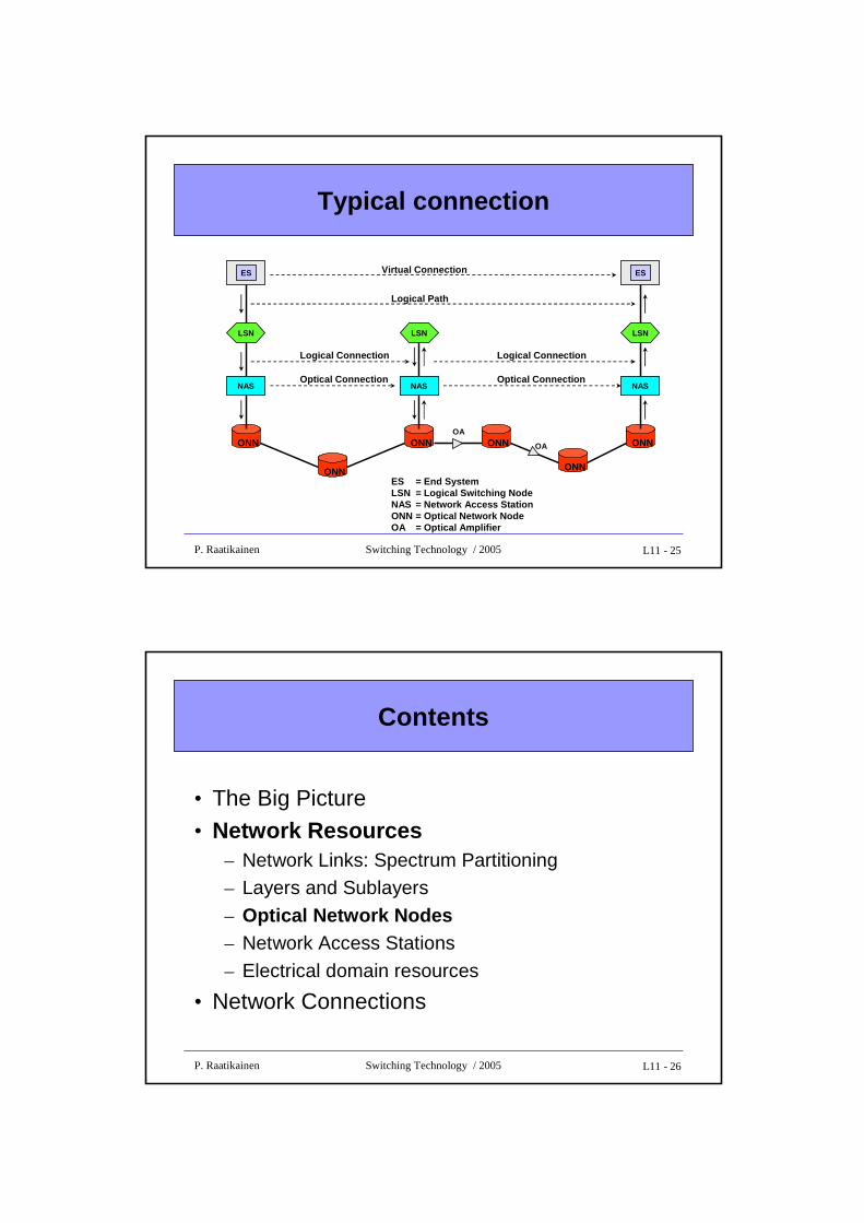
L11 - 25P. Raatikainen Switching Technology / 2005
Typical connection
ES = End SystemLSN = Logical Switching NodeNAS = Network Access StationONN = Optical Network NodeOA = Optical Amplifier
ONN
ONN
Virtual Connection
Logical Path
Logical Connection
Optical Connection
ONN ONN ONN
LSN
NAS
ES
LSN
NAS
LSN
NAS
ES
Logical Connection
Optical Connection
ONN
OA
OA
L11 - 26P. Raatikainen Switching Technology / 2005
Contents
• The Big Picture• Network Resources
– Network Links: Spectrum Partitioning– Layers and Sublayers
– Optical Network Nodes– Network Access Stations
– Electrical domain resources
• Network Connections
L11 - 27P. Raatikainen Switching Technology / 2005
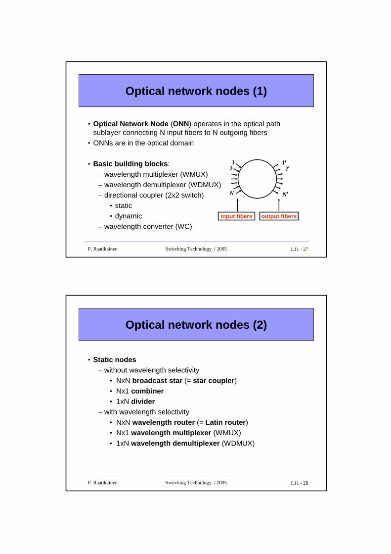
Optical network nodes (1)
• Optical Network Node (ONN) operates in the optical path sublayer connecting N input fibers to N outgoing fibers
• ONNs are in the optical domain
• Basic building blocks :
– wavelength multiplexer (WMUX)– wavelength demultiplexer (WDMUX)– directional coupler (2x2 switch)
• static• dynamic
– wavelength converter (WC)
12
1′′′′2′′′′
N N′′′′
input fibers output fibers
L11 - 28P. Raatikainen Switching Technology / 2005
Optical network nodes (2)
• Static nodes– without wavelength selectivity
• NxN broadcast star (= star coupler ) • Nx1 combiner• 1xN divider
– with wavelength selectivity• NxN wavelength router (= Latin router ) • Nx1 wavelength multiplexer (WMUX)
• 1xN wavelength demultiplexer (WDMUX)
L11 - 29P. Raatikainen Switching Technology / 2005
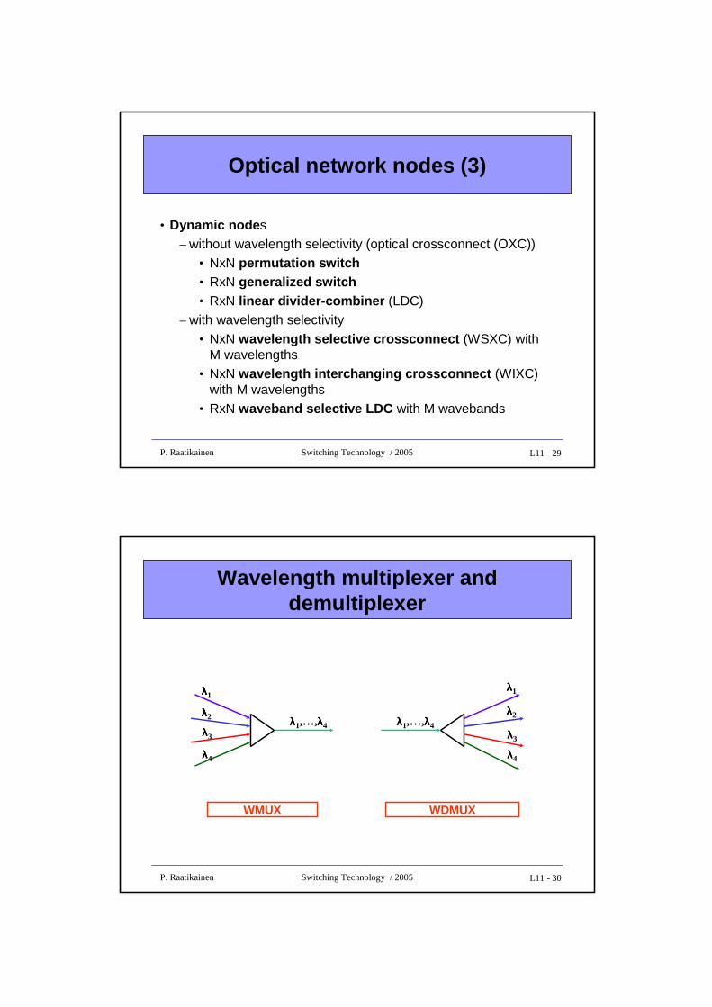
Optical network nodes (3)
• Dynamic node s– without wavelength selectivity (optical crossconnect (OXC))
• NxN permutation switch• RxN generalized switch• RxN linear divider-combiner (LDC)
– with wavelength selectivity
• NxN wavelength selective crossconnect (WSXC) with M wavelengths
• NxN wavelength interchanging crossconnect (WIXC) with M wavelengths
• RxN waveband selective LDC with M wavebands
L11 - 30P. Raatikainen Switching Technology / 2005
Wavelength multiplexer and demultiplexer
WDMUX
λλλλ1,…,λλλλ4
λλλλ1
λλλλ2
λλλλ3
λλλλ4
WMUX
λλλλ1,…,λλλλ4
λλλλ1
λλλλ2
λλλλ3
λλλλ4
L11 - 31P. Raatikainen Switching Technology / 2005
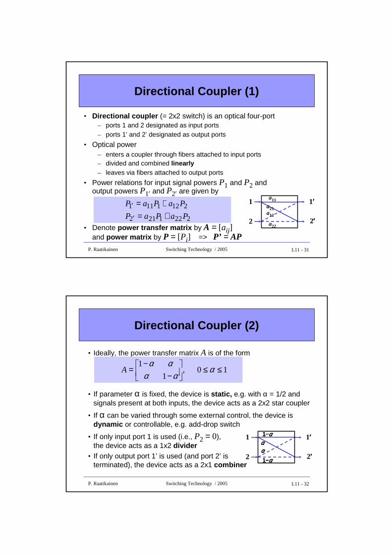
• Directional coupler (= 2x2 switch) is an optical four-port– ports 1 and 2 designated as input ports– ports 1’ and 2’ designated as output ports
• Optical power– enters a coupler through fibers attached to input ports – divided and combined linearly– leaves via fibers attached to output ports
• Power relations for input signal powers P1 and P2 and output powers P1′ and P2′ are given by
• Denote power transfer matrix by A = [aij ]and power matrix by P = [Pi] => P’ = AP
Directional Coupler (1)
2221212
2121111
PaPaP
PaPaP
+=+=
′
′ 1
2
1′′′′
2′′′′
a11
a21
a22
a12
L11 - 32P. Raatikainen Switching Technology / 2005
Directional Coupler (2)
• Ideally, the power transfer matrix A is of the form
• If parameter α is fixed, the device is static, e.g. with α = 1/2 and signals present at both inputs, the device acts as a 2x2 star coupler
• If α can be varied through some external control, the device is dynamic or controllable, e.g. add-drop switch
• If only input port 1 is used (i.e., P2 = 0), the device acts as a 1x2 divider
• If only output port 1’ is used (and port 2’ is terminated), the device acts as a 2x1 combiner
10 ,1
1≤≤
−
−= α
αααα
A
1
2
1′′′′
2′′′′
1111−−−−αααααααααααα1111−−−−αααα
L11 - 33P. Raatikainen Switching Technology / 2005
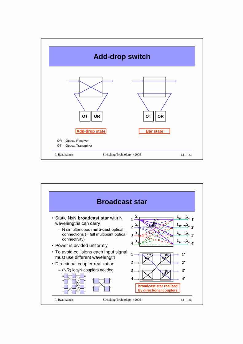
Add-drop switch
OT OR
Add-drop state
OT OR
Bar state
OR - Optical Receiver
OT - Optical Transmitter
L11 - 34P. Raatikainen Switching Technology / 2005
Broadcast star
• Static NxN broadcast star with N wavelengths can carry
– N simultaneous multi-cast optical connections (= full multipoint optical connectivity)
• Power is divided uniformly• To avoid collisions each input signal
must use different wavelength• Directional coupler realization
– (N/2) log2N couplers needed
1
2 2′′′′
3
4
λλλλ1
λλλλ2
λλλλ3
λλλλ4
3′′′′
4′′′′
1′′′′λλλλ1,…,λλλλ4
λλλλ1,…,λλλλ4
λλλλ1,…,λλλλ4
λλλλ1,…,λλλλ4
1/1/1/1/N1/1/1/1/N
1/1/1/1/N1/1/1/1/N
1
2
3
4
2′′′′
3′′′′
4′′′′
1′′′′1/1/1/1/21/1/1/1/2
1/1/1/1/21/1/1/1/2
1/1/1/1/21/1/1/1/2
broadcast star realizedby directional couplers
L11 - 35P. Raatikainen Switching Technology / 2005
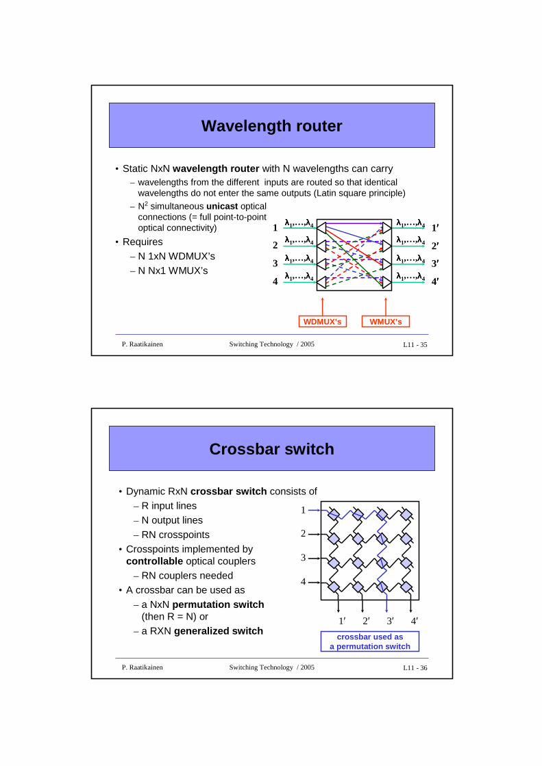
Wavelength router
• Static NxN wavelength router with N wavelengths can carry – wavelengths from the different inputs are routed so that identical
wavelengths do not enter the same outputs (Latin square principle)
– N2 simultaneous unicast optical connections (= full point-to-point optical connectivity)
• Requires– N 1xN WDMUX’s– N Nx1 WMUX’s
1
2 2′′′′
3
4
3′′′′
4′′′′
1′′′′λλλλ1,…,λλλλ4
λλλλ1,…,λλλλ4
λλλλ1,…,λλλλ4
λλλλ1,…,λλλλ4
λλλλ1,…,λλλλ4
λλλλ1,…,λλλλ4
λλλλ1,…,λλλλ4
λλλλ1,…,λλλλ4
WDMUX’s WMUX’s
L11 - 36P. Raatikainen Switching Technology / 2005
Crossbar switch
• Dynamic RxN crossbar switch consists of – R input lines– N output lines
– RN crosspoints• Crosspoints implemented by
controllable optical couplers– RN couplers needed
• A crossbar can be used as
– a NxN permutation switch(then R = N) or
– a RXN generalized switch
1
2
2′
3
4
3′ 4′1′crossbar used as
a permutation switch
L11 - 37P. Raatikainen Switching Technology / 2005
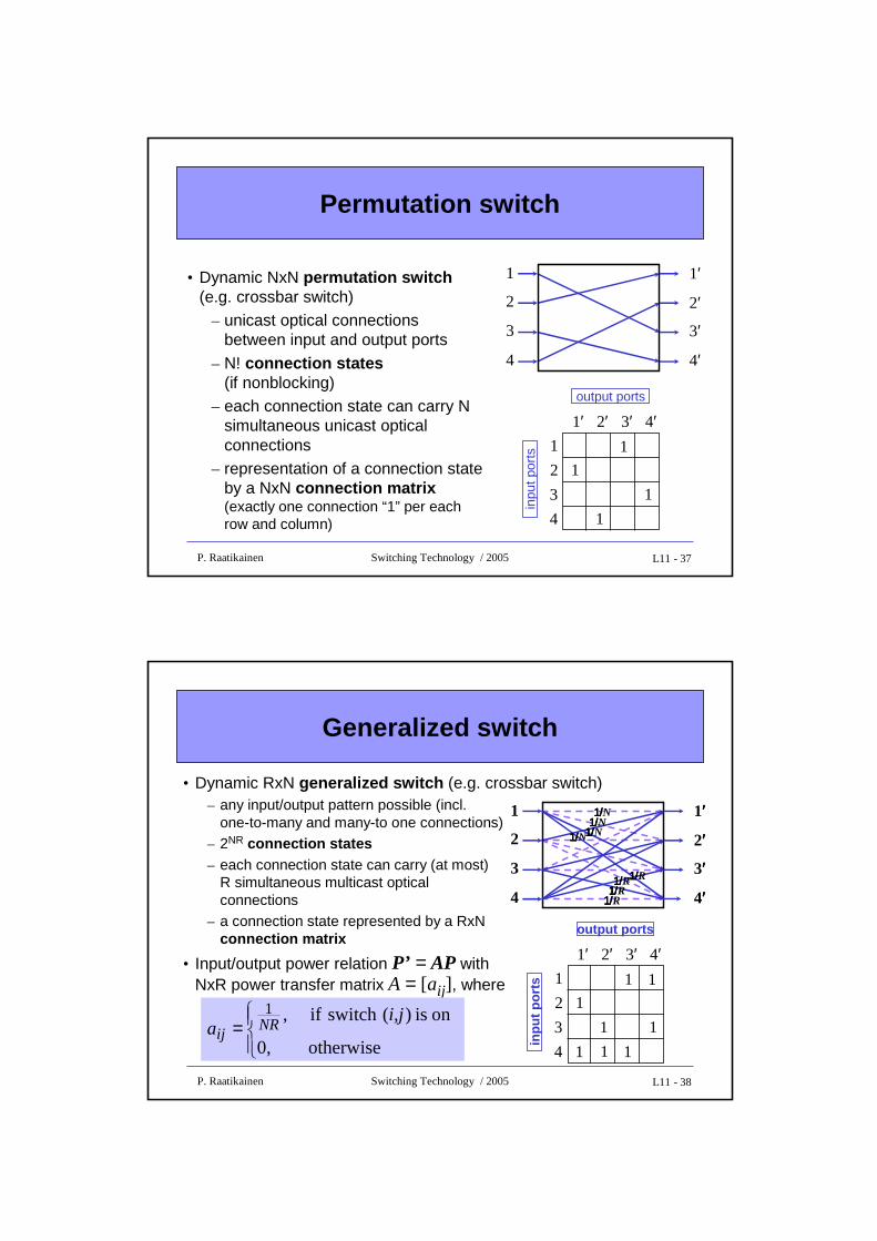
Permutation switch
• Dynamic NxN permutation switch(e.g. crossbar switch)
– unicast optical connections between input and output ports
– N! connection states(if nonblocking)
– each connection state can carry N simultaneous unicast optical connections
– representation of a connection state by a NxN connection matrix(exactly one connection “1” per each row and column)
1
2
3
4
2′ 3′ 4′1′
inpu
t por
ts
output ports
1
1
1
1
1
2 2′
3
4
3′
4′
1′
L11 - 38P. Raatikainen Switching Technology / 2005
• Dynamic RxN generalized switch (e.g. crossbar switch)– any input/output pattern possible (incl.
one-to-many and many-to one connections)– 2NR connection states– each connection state can carry (at most)
R simultaneous multicast optical connections
– a connection state represented by a RxNconnection matrix
• Input/output power relation P’ = AP with NxR power transfer matrix A = [aij ], where
Generalized switch
=otherwise ,0
on is )(switch if ,1 i,ja NR
ij
1
2
3
4
2′ 3′ 4′1′
inpu
t por
ts
output ports
1
1
1
1
1
1
1 1
1
2 2′′′′
3
4
3′′′′
4′′′′
1′′′′1/1/1/1/N1/1/1/1/N
1/1/1/1/N1/1/1/1/N
1/1/1/1/R1/1/1/1/R1/1/1/1/R
1/1/1/1/R
L11 - 39P. Raatikainen Switching Technology / 2005
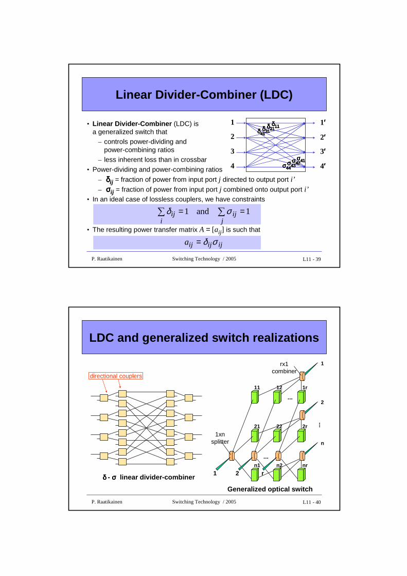
Linear Divider-Combiner (LDC)
• Linear Divider-Combiner (LDC) is a generalized switch that
– controls power-dividing and power-combining ratios
– less inherent loss than in crossbar
• Power-dividing and power-combining ratios
– δδδδij = fraction of power from input port j directed to output port i’– σσσσij = fraction of power from input port j combined onto output port i’
• In an ideal case of lossless couplers, we have constraints
• The resulting power transfer matrix A = [aij ] is such that
1 and 1 == ∑∑j
iji
ij σδ
ijijija σδ=
1
2 2′′′′
3
4
3′′′′
4′′′′
1′′′′δδδδ11111111δδδδ21212121δδδδ31313131δδδδ41414141
σσσσ41414141σσσσ42424242σσσσ43434343σσσσ44444444
L11 - 40P. Raatikainen Switching Technology / 2005
LDC and generalized switch realizations
directional couplers
δ δ δ δ - σσσσ linear divider-combiner
Generalized optical switch
1xnsplitter
...
1 2 rn1 n2 nr
21 22 2r
11 12 1r
1
2
n
...
...
rx1combiner
L11 - 41P. Raatikainen Switching Technology / 2005
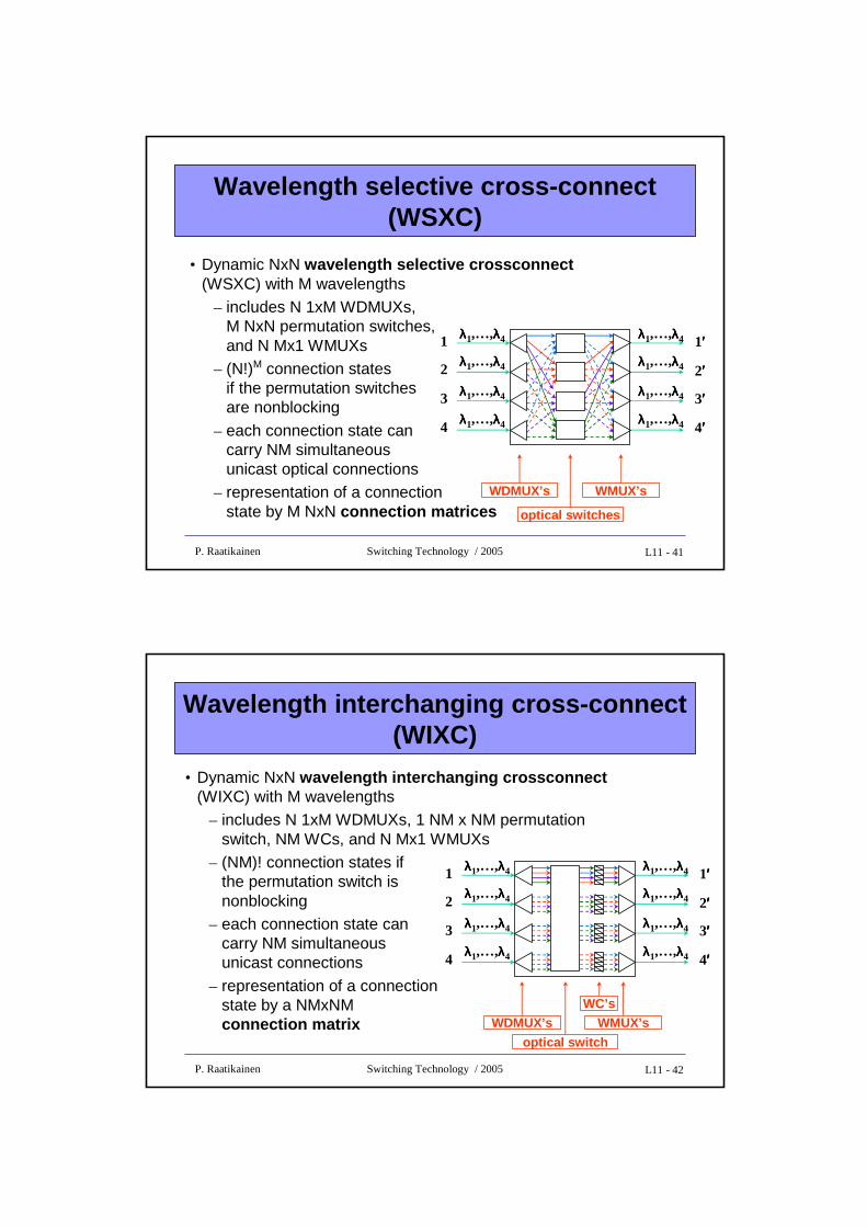
Wavelength selective cross-connect (WSXC)
• Dynamic NxN wavelength selective crossconnect(WSXC) with M wavelengths
– includes N 1xM WDMUXs, M NxN permutation switches, and N Mx1 WMUXs
– (N!)M connection states if the permutation switchesare nonblocking
– each connection state can carry NM simultaneous unicast optical connections
– representation of a connection state by M NxN connection matrices
WDMUX’s WMUX’s
2′′′′
3′′′′
4′′′′
1′′′′1
2
3
4
λλλλ1,…,λλλλ4
λλλλ1,…,λλλλ4
λλλλ1,…,λλλλ4
λλλλ1,…,λλλλ4
λλλλ1,…,λλλλ4
λλλλ1,…,λλλλ4
λλλλ1,…,λλλλ4
λλλλ1,…,λλλλ4
optical switches
L11 - 42P. Raatikainen Switching Technology / 2005
Wavelength interchanging cross-connect (WIXC)
• Dynamic NxN wavelength interchanging crossconnect(WIXC) with M wavelengths
– includes N 1xM WDMUXs, 1 NM x NM permutation switch, NM WCs, and N Mx1 WMUXs
– (NM)! connection states if the permutation switch is nonblocking
– each connection state can carry NM simultaneous unicast connections
– representation of a connection state by a NMxNMconnection matrix WDMUX’s WMUX’s
optical switch
WC’s
1
2 2′′′′
3
4
3′′′′
4′′′′
1′′′′λλλλ1,…,λλλλ4
λλλλ1,…,λλλλ4
λλλλ1,…,λλλλ4
λλλλ1,…,λλλλ4
λλλλ1,…,λλλλ4
λλλλ1,…,λλλλ4
λλλλ1,…,λλλλ4
λλλλ1,…,λλλλ4
L11 - 43P. Raatikainen Switching Technology / 2005
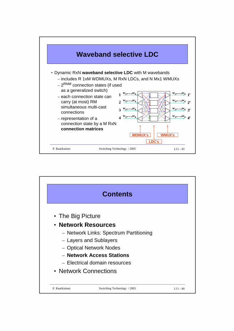
Waveband selective LDC
• Dynamic RxN waveband selective LDC with M wavebands– includes R 1xM WDMUXs, M RxN LDCs, and N Mx1 WMUXs– 2RNM connection states (if used
as a generalized switch) – each connection state can
carry (at most) RM simultaneous multi-cast connections
– representation of a connection state by a M RxNconnection matrices
WDMUX’s WMUX’s
2′′′′
3′′′′
4′′′′
1′′′′1
2
3
4
w1,…,w4
w1,…,w4
w1,…,w4
w1,…,w4
w1,…,w4
w1,…,w4
w1,…,w4
w1,…,w4
LDC’s
L11 - 44P. Raatikainen Switching Technology / 2005
Contents
• The Big Picture• Network Resources
– Network Links: Spectrum Partitioning– Layers and Sublayers
– Optical Network Nodes– Network Access Stations– Electrical domain resources
• Network Connections
L11 - 45P. Raatikainen Switching Technology / 2005
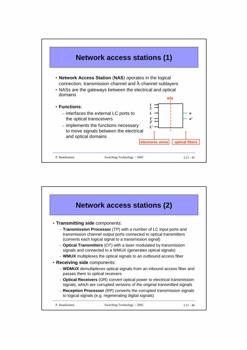
Network access stations (1)
• Network Access Station (NAS) operates in the logical connection, transmission channel and λ-channel sublayers
• NASs are the gateways between the electrical and optical domains
• Functions :– interfaces the external LC ports to
the optical transceivers– implements the functions necessary
to move signals between the electrical and optical domains
electronic wires optical fibers
12
1′′′′L
L ′′′′2′′′′
e/o
a
a’
L11 - 46P. Raatikainen Switching Technology / 2005
Network access stations (2)
• Transmitting side components:– Transmission Processor (TP) with a number of LC input ports and
transmission channel output ports connected to optical transmitters (converts each logical signal to a transmission signal)
– Optical Transmitters (OT) with a laser modulated by transmission signals and connected to a WMUX (generates optical signals)
– WMUX multiplexes the optical signals to an outbound access fiber
• Receiving side components:– WDMUX demultiplexes optical signals from an inbound access fiber and
passes them to optical receivers
– Optical Receivers (OR) convert optical power to electrical transmission signals, which are corrupted versions of the original transmitted signals
– Reception Processor (RP) converts the corrupted transmission signals to logical signals (e.g. regenerating digital signals)
L11 - 47P. Raatikainen Switching Technology / 2005
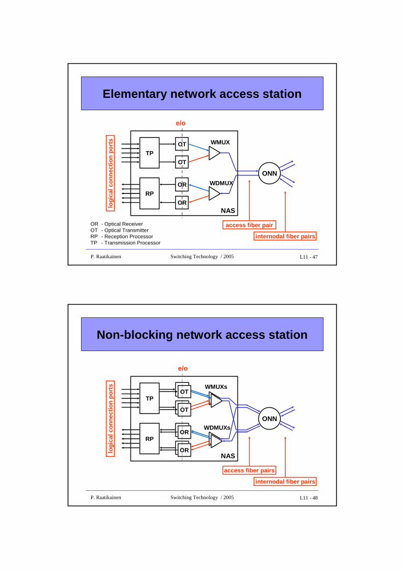
Elementary network access station
TP
RP
OT
OT
OR
OR
ONN
NAS
WMUX
WDMUX
e/o
access fiber pair
logi
cal c
onne
ctio
n po
rts
internodal fiber pairs
OR - Optical ReceiverOT - Optical TransmitterRP - Reception ProcessorTP - Transmission Processor
L11 - 48P. Raatikainen Switching Technology / 2005
Non-blocking network access station
TP
RP
ONN
NAS
WMUXs
WDMUXs
e/o
OT
OT
OR
OR
logi
cal c
onne
ctio
n po
rts
access fiber pairs
internodal fiber pairs
L11 - 49P. Raatikainen Switching Technology / 2005
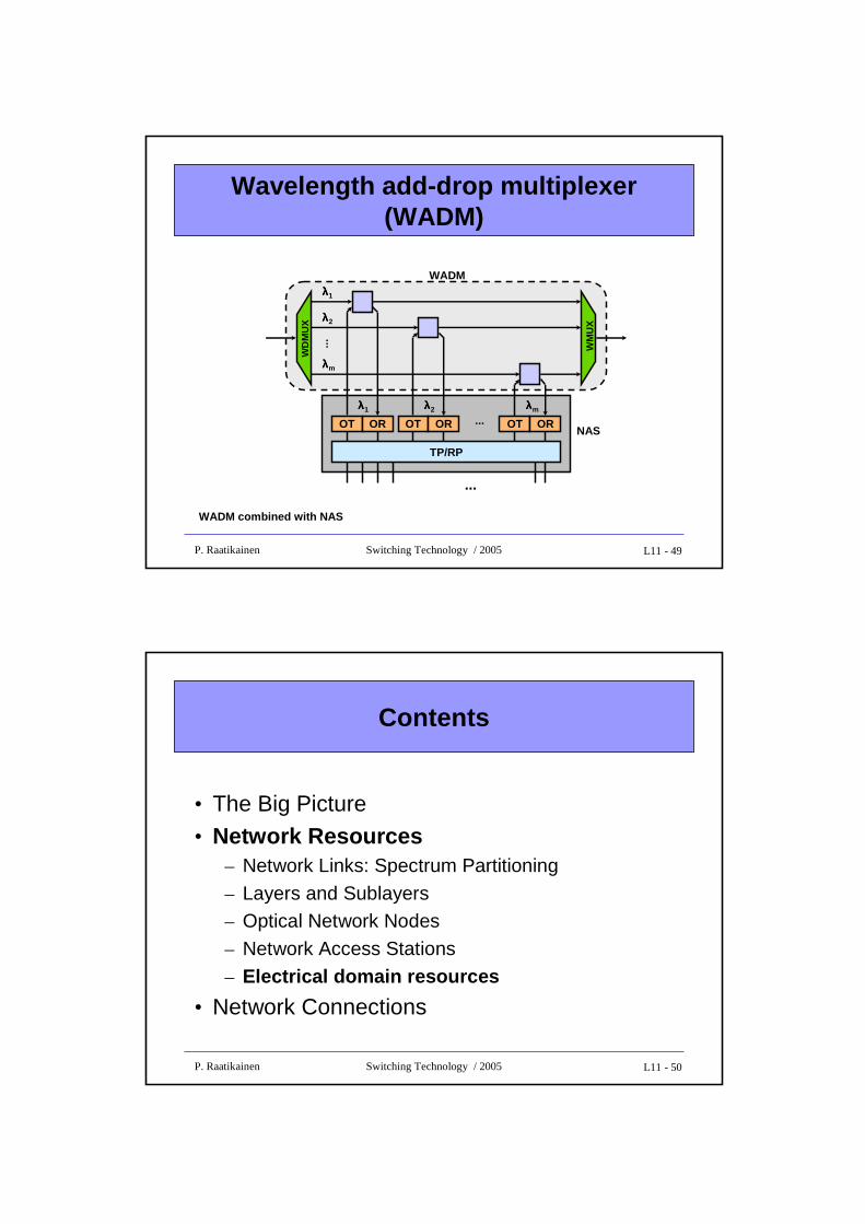
Wavelength add-drop multiplexer (WADM)
OT
λλλλ1
λλλλ2
λλλλm
OR
...
λλλλ1
OT OR
λλλλ2
OT OR
λλλλm
...
TP/RP
...
NAS
WADM
WD
MU
X
WM
UX
WADM combined with NAS
L11 - 50P. Raatikainen Switching Technology / 2005
Contents
• The Big Picture• Network Resources
– Network Links: Spectrum Partitioning
– Layers and Sublayers– Optical Network Nodes
– Network Access Stations
– Electrical domain resources
• Network Connections
L11 - 51P. Raatikainen Switching Technology / 2005
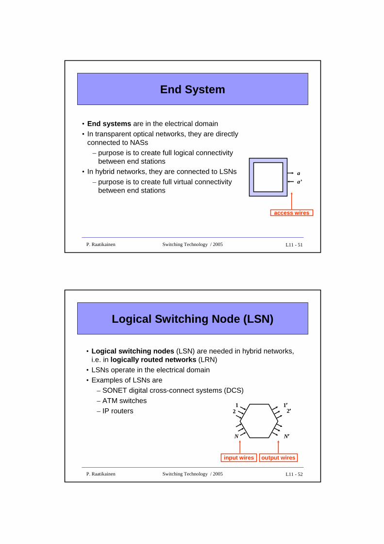
End System
• End systems are in the electrical domain• In transparent optical networks, they are directly
connected to NASs– purpose is to create full logical connectivity
between end stations• In hybrid networks, they are connected to LSNs
– purpose is to create full virtual connectivity between end stations
access wires
a
a’
L11 - 52P. Raatikainen Switching Technology / 2005
Logical Switching Node (LSN)
• Logical switching nodes (LSN) are needed in hybrid networks, i.e. in logically routed networks (LRN)
• LSNs operate in the electrical domain• Examples of LSNs are
– SONET digital cross-connect systems (DCS)
– ATM switches– IP routers
12
1′′′′2′′′′
N N′′′′
input wires output wires
L11 - 53P. Raatikainen Switching Technology / 2005
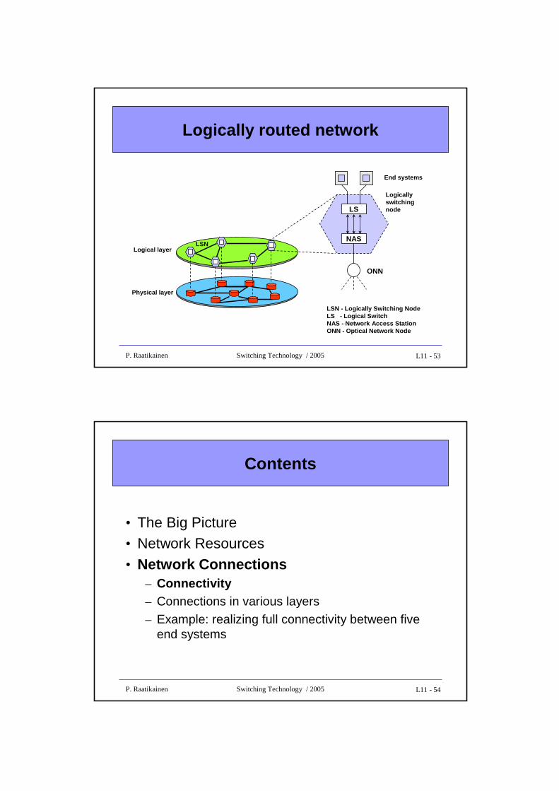
Logically routed network
LSN - Logically Switching NodeLS - Logical SwitchNAS - Network Access StationONN - Optical Network Node
Physical layer
Logical layer
LS
NAS
ONN
LSN
Logicallyswitchingnode
End systems
L11 - 54P. Raatikainen Switching Technology / 2005
Contents
• The Big Picture• Network Resources• Network Connections
– Connectivity– Connections in various layers
– Example: realizing full connectivity between five end systems
L11 - 55P. Raatikainen Switching Technology / 2005
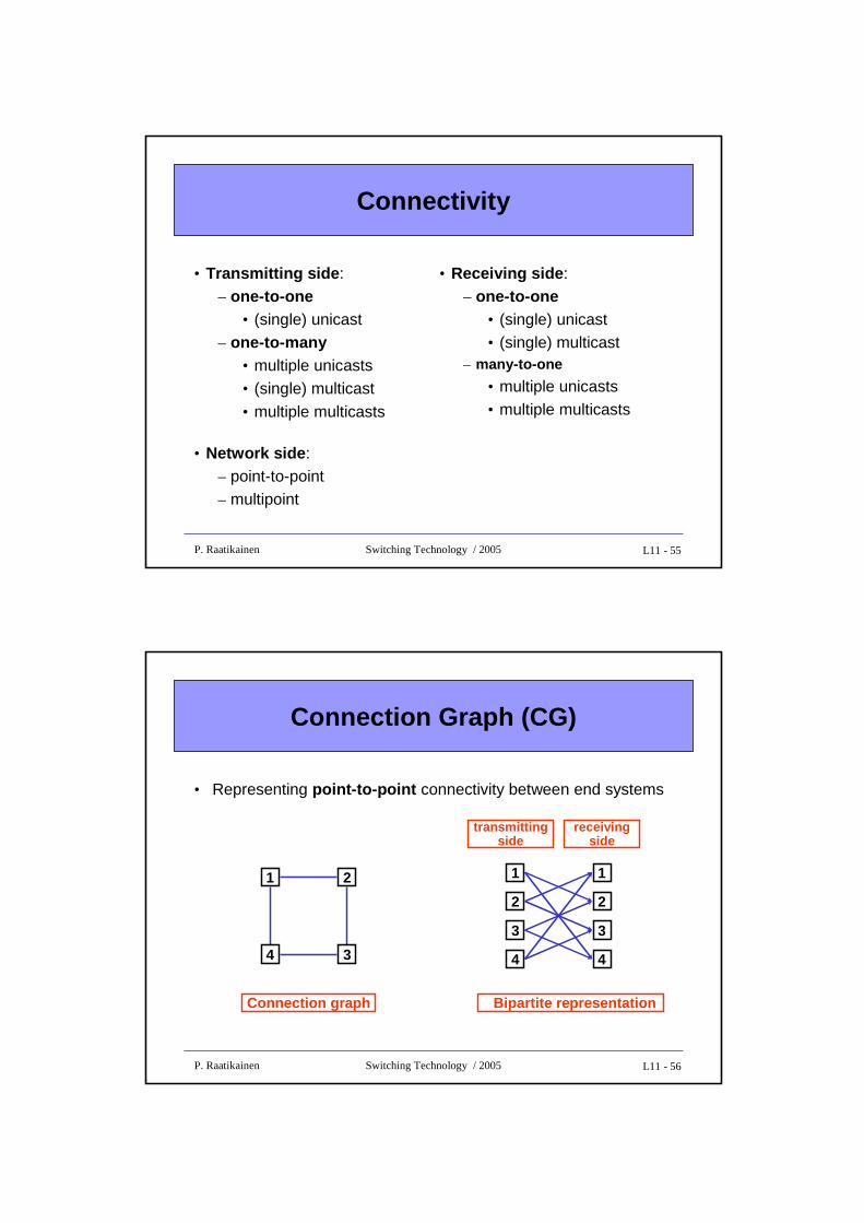
Connectivity
• Transmitting side :– one-to-one
• (single) unicast– one-to-many
• multiple unicasts• (single) multicast
• multiple multicasts
• Network side :– point-to-point– multipoint
• Receiving side :– one-to-one
• (single) unicast• (single) multicast
– many-to-one
• multiple unicasts• multiple multicasts
L11 - 56P. Raatikainen Switching Technology / 2005
Connection Graph (CG)
• Representing point-to-point connectivity between end systems
1
Connection graph
2
4 3
Bipartite representation
1
2
4
3
1
2
4
3
transmittingside
receivingside
L11 - 57P. Raatikainen Switching Technology / 2005
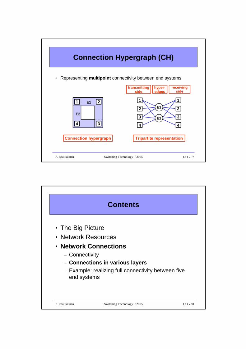
Connection Hypergraph (CH)
• Representing multipoint connectivity between end systems
1
Connection hypergraph
2
4 3
E1
E2
Tripartite representation
1
2
4
3
1
2
4
3
transmittingside
receivingside
E1
hyper-edges
E2
L11 - 58P. Raatikainen Switching Technology / 2005
Contents
• The Big Picture• Network Resources• Network Connections
– Connectivity
– Connections in various layers– Example: realizing full connectivity between five
end systems
L11 - 59P. Raatikainen Switching Technology / 2005
Connections in various layers
• Logical connection sublayer
– Logical connection (LC) is a unidirectional connection between external ports on a pair of source and destination network access stations (NAS)
• Optical connection sublayer
– Optical connection (OC) defines a relation between one transmitter and one or more receivers, all operating in the samewavelength
• Optical path sublayer
– Optical path (OP) routes the aggregate power on one waveband on a fiber, which could originate from several transmitters within the waveband
L11 - 60P. Raatikainen Switching Technology / 2005
Notation for connections in various layers
• Logical connection sublayer– [a, b] = point-to-point logical connection from an external port on station a
to one on station b– [a, {b, c, …}] = multi-cast logical connection from a to set { b, c, …}
• station a sends the same information to all receiving stations
• Optical connection sublayer– (a, b) = point-to-point optical connection from station a to station b
– (a, b)k = point-to-point optical connection from a to b using wavelength λk– (a,{b,c,…} ) = multi-cast optical connection from a to set { b,c,…}
• Optical path sublayer– ⟨a, b⟩ = point-to-point optical path from station a to station b
– ⟨a, b⟩k = point-to-point optical path from a to b using waveband wk– ⟨a, {b, c, …}⟩ = multi-cast optical path from a to set { b,c,…}
L11 - 61P. Raatikainen Switching Technology / 2005
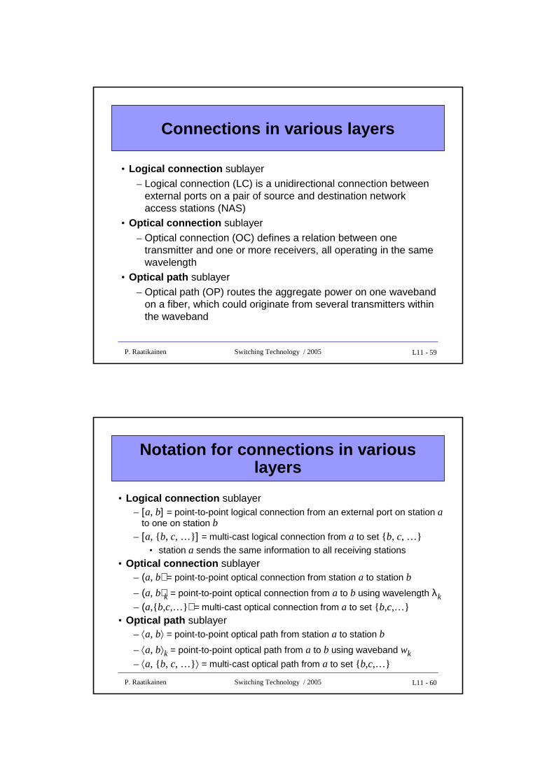
Example of a logical connection between two NASs
ONN
TP RP
Electrical Electrical
Optical Opticalλλλλ1 ... λλλλm λλλλm ... λλλλ1
WMUX WDMUX
OT OR
NAS NAS
w2 ONN
ONNw1
Logical connection [A,B]
Transmission channel
Optical connection (A,B) λλλλ1
λλλλ- channel
Optical path <A,B> w1
L11 - 62P. Raatikainen Switching Technology / 2005
Contents
• The Big Picture• Network Resources• Network Connections
– Connectivity– Connections in various layers
– Example: realizing full connectivity between five end systems
L11 - 63P. Raatikainen Switching Technology / 2005
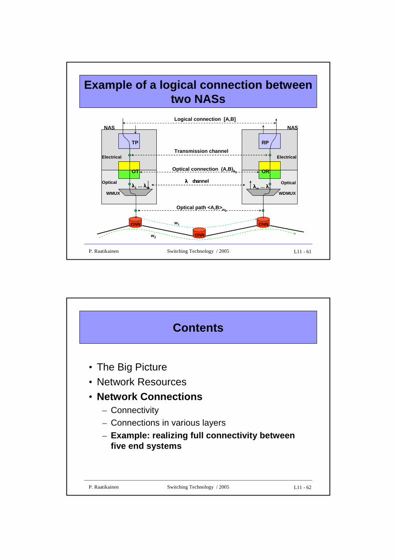
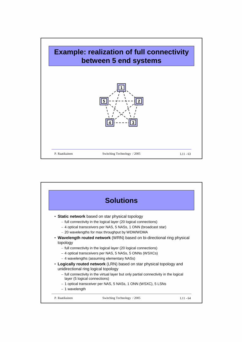
Example: realization of full connectivity between 5 end systems
5 2
4 3
1
L11 - 64P. Raatikainen Switching Technology / 2005
Solutions
• Static network based on star physical topology– full connectivity in the logical layer (20 logical connections)
– 4 optical transceivers per NAS, 5 NASs, 1 ONN (broadcast star)– 20 wavelengths for max throughput by WDM/WDMA
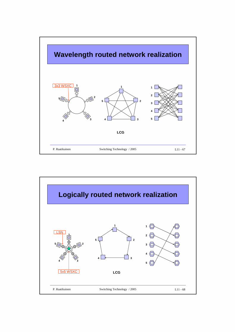
• Wavelength routed network (WRN) based on bi-directional ring physical topology
– full connectivity in the logical layer (20 logical connections)– 4 optical transceivers per NAS, 5 NASs, 5 ONNs (WSXCs)
– 4 wavelengths (assuming elementary NASs)
• Logically routed network (LRN) based on star physical topology and unidirectional ring logical topology
– full connectivity in the virtual layer but only partial connectivity in the logical layer (5 logical connections)
– 1 optical transceiver per NAS, 5 NASs, 1 ONN (WSXC), 5 LSNs– 1 wavelength
L11 - 65P. Raatikainen Switching Technology / 2005
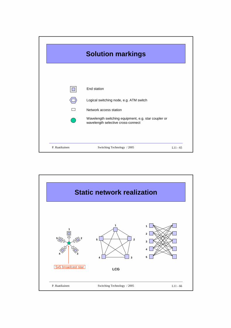
Solution markings
End station
Logical switching node, e.g. ATM switch
Network access station
Wavelength switching equipment, e.g. star coupler or wavelength selective cross-connect
L11 - 66P. Raatikainen Switching Technology / 2005
Static network realization
5x5 broadcast starLCG
1
2
3
4
5
1
25
4 3
1
25
4 3
L11 - 67P. Raatikainen Switching Technology / 2005
Wavelength routed network realization
3x3 WSXC 1
2
3
4
5
1
25
4 3
1
25
4 3
LCG
L11 - 68P. Raatikainen Switching Technology / 2005
Logically routed network realization
5x5 WSXC
LSN
1
2
3
4
5
1
25
4 3
1
25
4 3
LCG