introduction to hydraulic design of sewers intro to hydraulic... · an introduction to hydraulic...
TRANSCRIPT

Introduction to Hydraulic Design of Sewers Course No: C02-031
Credit: 2 PDH
J. Paul Guyer, P.E., R.A., Fellow ASCE, Fellow AEI
Continuing Education and Development, Inc. 9 Greyridge Farm Court Stony Point, NY 10980 P: (877) 322-5800 F: (877) 322-4774 [email protected]

J. Paul Guyer, P.E., R.A. Paul Guyer is a registered civil engineer, mechanical engineer, fire protection engineer, and architect with over 35 years experience in the design of buildings and related infrastructure. For an additional 9 years he was a senior advisor to the California Legislature on infrastructure and capital outlay issues. He is a graduate of Stanford University and has held numerous national, state and local positions with the American Society of Civil Engineers and National Society of Professional Engineers.
An Introduction to Hydraulic Design of Sewers
G u y e r P a r t n e r s4 4 2 4 0 C l u b h o u s e D r i v e
E l M a c e r o , C A 9 5 6 1 8( 5 3 0 ) 7 5 8 - 6 6 3 7
j p g u y e r @ p a c b e l l . n e t
© J. Paul Guyer 2010 1

© J. Paul Guyer 2010 2
This course is adapted from the Unified Facilities Criteria of the United States government, which is in the public domain, has unlimited distribution and is not copyrighted.

CONTENTS
1. QUANTITY OF WASTEWATER
2. GRAVITY SEWER DESIGN
3. REQUIRED PUMPING CAPACITY
4. DEPRESSED SEWERS
5. HYDROGEN SULFIDE IN SEWERS
6. MANHOLES
7. BUILDING CONNECTIONS
8. CLEANOUTS
9. PUMPING STATIONS AND EQUIPMENT
© J. Paul Guyer 2010 3

1. QUANTITY OF WASTEWATER. For any segment of proposed sewer, the design
wastewater flow must be determined. Sanitary or domestic wastes based on the
population served by a given segment, extraneous infiltration/inflow, and contributing
industrial flows must be added to produce the design flow. Where existing flow records
or data showing required flow capacity are not available, the methods and criteria
discussed below will be used to develop design flows.
1.1 TRIBUTARY AREA. This is the area contributing wastewater to a particular sewer
segment. The quantity of wastewater which is collected by a particular segment is
dependent upon the types of personnel and industrial activities which are regularly
found in the area. Where no information is available on existing areas to be served, a
survey will be required to determine the number and classification of persons and the
types of industries.
1.2 SANITARY OR DOMESTIC WASTES. 1.2.1 CONTRIBUTING POPULATION. Domestic wastewater quantities normally are
to be computed on a contributing population basis. The population to be used in design
depends upon the type of area which the sewer serves. If the area is strictly residential,
the design population is based on full occupancy of all housing served. If the area
served is entirely industrial, the design population is the greatest number employed in
the area at any time, even though some of these persons may also be included in the
design of sewers in the residential area. For sewers serving both residential and
industrial areas, the design population includes residents and nonresidents, but in the
design of these sewers obviously no person should be counted more than once.
Allowances will be made for future population changes based on facility personnel
requirements and master planning projections.
1.2.2 AVERAGE DAILY FLOW. The average daily flow will be computed by
multiplying the resident and nonresident contributing populations by the appropriate per
© J. Paul Guyer 2010 4

capita allowances and adding the two flows. The average daily flow represents the total
waste volume generated over a 24-hour period. However, it is not a realistic indicator of
the rate of flow when wastes are generated over shorter periods of 8, 10, 12 hours, etc.
Thus, the average daily flow will be used only for designing sewers to serve the entire
installation, or large sections of the installation, and where a major portion of the
wastewater is generated by residents over a 24-hour period.
1.2.2.1 Allowances do not include industrial and process wastes.
1.2.2.2 These values represent domestic waste quantities for resident personnel
averaged over the entire installation for a 24-hour period. Nonresident personnel and
civilian employees working 8-hour shifts may be allowed 115 liters/capita/day (30
gallons/capita/day). Normally, these quantities are to be used in design of wastewater
treatment facilities. However, they will also be used for sizing interceptors, trunk sewers
and pumping stations serving large portions of the installation.
1.2.2.3 For design of sewers serving smaller areas where several buildings or a group
of buildings must be considered, the appropriate wastewater allowances shown in the
table or obtained from standard textbooks will be used.
1.2.2.4 In residential areas, each housing unit may be assigned 3.6 residents for the
purpose of calculating populations.
1.2.2.5 For hospitals, no separate allowance will be made for non-patients and
employees working shifts.
1.2.3 AVERAGE HOURLY FLOWRATE. When designing sewers to serve small areas
of the installation where several buildings or a group of buildings are under
consideration, and where the majority of wastewater is generated by nonresidents or
other short term occupants, the average hourly flowrate will be used. The average
hourly flowrate will be computed based on the actual period of waste generation. For
example, 1000 nonresidents at 115 Lcpd would generate 115,000 liters in 8 hours for an
average hourly flowrate of 14,375 L/h or 345,000 L/d. Note that the average daily flow
would still be 115,000 L/d, or 115,000 liters in 24 hours, but the sewer must be designed
hydraulically to carry the 115,000 liters in 8 hours, not 24 hours.
© J. Paul Guyer 2010 5

1.2.4 PEAK DIURNAL FLOWRATE. The normal daily range of the rate of flow, or the
diurnal pattern, is from approximately 40 percent to 250 percent of the average daily
flow. The peak daily or diurnal flowrate is an important factor in sewer design, especially
when minimum velocities are to be provided on a daily basis. The peak diurnal flowrate
will be taken as one half of the extreme peak flowrate.
1.2.5 EXTREME PEAK FLOWRATE. Extreme peak rates of flow occur occasionally
and must be considered. Sewers will be designed with adequate capacity to handle
these extreme peak flowrates. Ratios of extreme peak flowrates to average flows will be
calculated with the use of the following formula:
R = C/Q 0.167
where:
R = ratio of extreme peak flowrate to average flow
Q = average daily flow or average hourly flowrate in liters per day (gallons per
day),
or liters per hour (gallons per hour), and
C = constant, 47.71 for L/d (38.2 for gpd) or 28.10 for L/h (22.5 for gph)
When designing sewers to serve the entire installation, or large areas of the installation,
and where a major portion of the wastewater is generated by residents over a 24-hour
period, the average daily flow will be used in the formula, and the extreme peak flowrate
will be computed by multiplying the average daily flow by the ratio R. However, for
sewers serving small areas of the installation where several buildings or a group of
buildings are being considered, and where the majority of wastewater is generated by
nonresidents or other short term occupants, the average hourly flowrate will be used in
the formula, and the extreme peak flowrate will be computed by multiplying the average
hourly flowrate by the ratio R.
© J. Paul Guyer 2010 6

1.3 INFILTRATION AND INFLOW. Extraneous flows from groundwater infiltration enter
the sewer system through defective pipe, joints, fittings and manhole walls. Sources of
inflow include connections from roof leaders, yard drains, storm sewers, cooling water
discharges and foundation drains, in addition to submerged manhole covers.
1.3.1 IN COMPUTING WASTEWATER FLOWS FOR NEW SEWERS, design
allowances for groundwater infiltration may be 45 to 95 liters/day per millimeter diameter
per kilometer of pipe (500 to 1000 gallons/day per inch diameter per mile of pipe), and
will be added to the peak rate of flow.
1.3.2 WHERE INFILTRATION/INFLOW MUST BE CALCULATED FROM AN EXISTING COLLECTION SYSTEM, attempts must be made to obtain flow records from
treatment facilities or pumping stations which will provide information on the magnitude
of I/I quantities. In the absence of such flow data, and depending on the scope of the
project, it may be necessary to measure flows in the existing system. Where this is not
possible or feasible, allowances of 23,500 to 235,000 Lpd/km (10,000 to 100,000
gpd/mile) of pipe may be used depending on the size and age of the sewers, materials
of construction, and the soil and ground-water conditions. Installation personnel will
usually have some knowledge of these matters and should be aware of major problems.
Where I/I is known to be excessive, it should be determined prior to design if corrective
measures are planned for the existing system, or if U.S. Environmental Protection
Agency (EPA) evaluation and rehabilitation programs will be implemented.
1.4 INDUSTRIAL WASTE FLOWS. Industrial waste quantities from plants, technical
laboratories, laundries, vehicle maintenance shops, wash racks, plating shops, and
such industries cannot be computed totally on a population or fixture unit basis. Flows
from such plants depend upon the type and extent of the activities. Industrial waste
sewers and sanitary sewers will be designed for the peak industrial flow as determined
for the particular industrial process or activity involved.
© J. Paul Guyer 2010 7
1.5 FIXTURE UNIT FLOW. The size of building connections will in all cases be large
enough to discharge the flow computed on a fixture unit basis. This requirement applies
to building connections only, and not to the lateral or other sewers to which they
connect.
2. GRAVITY SEWER DESIGN. Sewers will be designed to discharge the wastewater
flows as required. Generally, it is not desirable to design sewers for full flow, even at
peak rates. Flows above 90 to 95 percent of full depths are considered unstable, and
may result in a sudden loss of carrying capacity with surcharging at manholes. In
addition, large trunk and interceptor sewers laid on flat slopes are less subject to wide
fluctuations in flow, and if designed to flow full may lack sufficient air space above the
liquid to assure proper ventilation. Adequate sewer ventilation is a desirable method of
preventing the accumulation of explosive, corrosive or odorous gases, and of reducing
the generation of hydrogen sulfide. Therefore, trunk and interceptor sewers will be
designed to flow at depths not exceeding 90 percent of full depth; laterals and main
sewers, 80 percent; and building connections, 70 percent. However, regardless of flow
and depth the minimum sizes to be used are 150 millimeter (6-inch) for building
connections and 200 millimeter (8-inch) for all other sewers. Building connections that
do not carry sanitary waste and will transport liquids with little or no solids, such as
condensate lines, can be smaller than 150 millimeters (6 inches), but no smaller than
100 millimeters (4 inches) is recommended for most situations. Industrial applications
will use the same design criteria as sanitary sewers except pipe material that is resistant
to the waste will be specified. The following formula, charts, procedures and criteria will
be used for design.
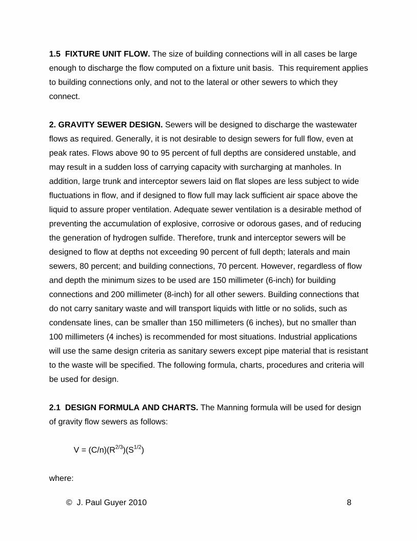
2.1 DESIGN FORMULA AND CHARTS. The Manning formula will be used for design
of gravity flow sewers as follows:
V = (C/n)(R2/3)(S1/2)
where:
© J. Paul Guyer 2010 8

C = 1 for SI units (1.486 for IP units)
V = velocity in meters per second (feet per second)
n = coefficient of pipe roughness
R = hydraulic radius in meters (feet), and
S = slope of energy line in meters per meter (feet per foot)
2.1.1 ROUGHNESS COEFFICIENT. Values of n to be used in the formula range from
0.013 to 0.015. The lowest n values apply to new or relatively new pipe (in sections
greater than 1.5 m (5 feet)) with smooth interior surfaces, smooth bore, even joints, in
excellent to good condition and well constructed. Higher n values are required for older
pipe with rough interior surfaces, open or protruding joints, in fair to bad condition and
poorly constructed. Values up to 0.017 are often justified for very old pipe (such as brick
or block sewers) in extreme deterioration, or pipe very poorly constructed with improper
alignment, sags and bellies, cracked or offset joints, broken wall sections or internal
corrosion. Some manufacturers of plastic and asbestos cement pipe report n values of
0.009 to 0.011. However, due to uncertainties in design and construction, plus a desire
to provide a margin of safety, n values smaller than 0.013 will not normally be permitted.
Variation of n with depth of flow has been shown experimentally, and may be
considered in designing sewers to flow partially full. A solution to the Manning formula
for full pipe flow is shown in figure 1.
© J. Paul Guyer 2010 9
Figure 1
Chart for Manning Formula
2.1.2 VELOCITY. Sewers will be designed to provide a minimum velocity of 0.60
meters per second (2.0 feet per second) at the average daily flow, or average hourly
flowrate, and a minimum velocity of 0.75 to 1.05 m/s (2.5 to 3.5 fps) at the peak diurnal
flowrate. When velocities drop below 0.30 m/s (1.0 fps) during periods of low flow,
organic solids suspended in the wastewater can be expected to settle out in the sewer.
Sufficient velocity (0.75 to 1.05 m/s (2.5 to 3.5 fps)) must be developed regularly, once
or twice daily as a minimum, to re-suspend and flush out solids which may have been
deposited during low flows. A velocity of 0.75 m/s (2.5 fps) minimum is required to keep
grit and sand suspended. However, new sewers which are properly designed and
© J. Paul Guyer 2010 10

constructed should contain only minor quantities of grit or sand. Maximum velocity is set
at 3.00 m/s (10.0 fps) in the event that grit becomes a problem.
2.1.3 SLOPE. Assuming uniform flow, the value of S in the Manning formula is
equivalent to the sewer invert slope. Pipe slopes must be sufficient to provide the
required minimum velocities and depths of cover on the pipe. Although it is desirable to
install large trunk and interceptor sewers on flat slopes to reduce excavation and
construction costs, the resulting low velocities may deposit objectionable solids in the
pipe creating a buildup of hydrogen sulfide, and thus will be avoided.
2.1.4 COVER. Adequate cover must be provided for frost protection. Generally, a
minimum 0.6 meters (2 feet) of earth will be required to protect the sewer against
freezing. Where frost penetrates to a considerably greater depth and lasts for an
appreciable length of time, the wastes may not contain sufficient heat to prevent the
gradual cooling of surrounding earth and buildup of an ice film inside the pipe. Under
these conditions, greater cover will be required. Sufficient cover must also be provided
to protect the pipe against structural damage due to superimposed surface loadings.
2.2 DESIGN PROCEDURE. After a preliminary layout has been made, a tabulation
should be prepared in convenient form setting forth the following information for each
sewer section:
• Designation of manholes by numerals or letters.
• Contributing populations - resident and nonresident.
• Design flows - average, daily peak, and extreme peak.
• Length of sewer.
• Invert elevations.
• Invert slope or gradient.
• Pipe diameter and roughness coefficient.
• Flow depths at design flows.
• Velocities at design flows.
• Depths of cover on the pipe - maximum and minimum.
© J. Paul Guyer 2010 11

2.3 HYDRAULIC PROFILE. In most situations where small to medium sized gravity
sewers are installed in long runs, it will be safe to assume uniform flow throughout the
entire length of conduit. However, in cases where larger sewers, 600-millimeter (24-
inch) diameter and above, are constructed in runs of less than 30 meters (100 feet), and
with a number of control sections where nonuniform flow may occur, a plot of the
hydraulic profile is recommended. For process and plant piping at wastewater treatment
facilities, a hydraulic profile is always required. Methods used to calculate and plot
hydraulic profiles including backwater curves, drawdown curves and hydraulic jumps,
will conform to those presented in standard hydraulics textbooks.
2.4 CRITICAL FLOW. Gravity sewers will ordinarily be designed to maintain subcritical
flow conditions in the pipe throughout the normal range of design flows. However, there
are exceptions in which super critical flow may be required, and will be justified.
Minimum sized sewers (150- and 200-millimeter (6- and 8-inch)) designed to discharge
very low flows, must occasionally be placed on slopes steeper than critical in order to
provide minimum velocities. In addition, small to medium sized sewers when required to
discharge unusually large flows, may necessitate super critical slopes. Finally, steep
slopes may be unavoidable due to natural topography and ground conditions. Where
super critical flow will occur, care must be taken in the design to insure that downstream
pipe conditions do not induce a hydraulic jump or other flow disturbance. Depths of flow
within 10 to 15 percent of critical are likely to be unstable and will be avoided where
pipes will flow from 50 to 90 percent full. Critical depths for various flows and pipe
diameters can be obtained from standard hydraulics textbooks.
2.5 COMPUTER PROGRAMS. Numerous commercial computer programs are
available for modeling, data management (such as location, diameter, depth, slope, and
capacity of each sewer component), design, and analysis of sewer systems. As well as
being used to design new systems, such programs can assist in assessing impacts of
changes and additions to existing systems and thus help optimize designs. Three-
dimensional models may allow designers to detect interference with other utilities.
© J. Paul Guyer 2010 12

3. REQUIRED PUMPING CAPACITY. Proper selection of the number and capacity of
pumping units is dependent upon the quantity and variation of wastewater flows to be
handled. Except as indicated below for small stations, pumping units will be selected to
handle the normal daily range of wastewater flows generated in the service area. The
number and capacity of pumps provided will be sufficient to discharge the minimum,
average, peak daily and extreme peak flowrates. Pumping capacity will be adequate to
discharge the peak flowrates with the largest pump out of service. Consideration will be
given to future conditions which may occur. Normally, where future development and
population increases are projected for the area, pumps will be designed for initial
conditions only, and the station will be provided adequate room for expansion of
pumping capacity at a later date. Expansion of pumping capacity can be accomplished
with the installation of additional pumping units, larger pumps, impellers, drive units,
adjustable or variable speed drives. However, some situations may warrant provision of
capacity for future increases initially, for economic or other reasons. Each case will be
analyzed individually.
3.1 SMALL STATIONS. Pumping stations required for small remote areas which
generate extreme peak flowrates of less than 45 L/s (700 gpm), and where the
possibility of future expansion is unlikely, and grinder pump installations serving three or
more buildings, will be provided with two identical pumping units. Each pumping unit will
be of the constant speed type, and will be capable of discharging the extreme peak
wastewater flowrate. The station will be designed to alternate between zero discharge
and peak discharge. This arrangement will provide 100 percent standby capacity to
allow for necessary maintenance and repairs. Pneumatic ejector stations will be
provided with duplex ejectors each sized for the extreme peak flowrate.
3.2 LARGE STATIONS. Pumping stations serving large areas of the installation, and
especially stations where the entire wastewater flow or major portions thereof must be
pumped to the treatment facility, will be designed so far as practicable to operate on a
continuous basis. The rate of pumpage must change in increments as the inflow to the
© J. Paul Guyer 2010 13
station varies. This mode of operation will normally require two or more wastewater
pumps of the constant or variable speed type, operating in single or multiple pump
combinations, as required to match the incoming flowrates.
4. DEPRESSED SEWERS.
4.1 VELOCITY AND FLOW ANALYSIS. Since a depressed sewer, or inverted siphon,
is installed below the hydraulic grade line, the pipe will always be full of wastewater
under pressure, even though there may be little or no flow. Thus, the design requires
special care to secure velocities that will prevent clogging due to sedimentation of
solids. The velocity should be as high as practicable, with a minimum requirement set at
1 meter per second (3.0 feet per second). Hydraulic calculations may be based on the
Manning formula or Hazen-Williams analysis. A minimum Manning roughness
coefficient of 0.015 is recommended due to possible accumulations of grease and other
materials on pipe walls. The pipe will be as small as the available head permits except
that pipe smaller than 150-millimeter (6-inch) is not permitted. Inasmuch as the sewer
must be of sufficient size to discharge the extreme peak flows, better velocities for the
normal range of flows can often be obtained by using several small pipes instead of one
large pipe. This requires an entrance box equipped with a diversion gate for the periodic
alternation of pipes in service and with an overflow weir so arranged that, when the flow
exceeds the capacity of one pipe, the excess can overflow to the other pipes. However,
conditions might be such that two or three pipes in lieu of one would not be
advantageous or necessary. Each case will be analyzed individually.
4.2 CLEANING AND INSPECTION. Depressed sewers should be flushed frequently
and inspected to make sure that obstructions are removed. Therefore, manhole
structures or cleanout chambers will be required at each end of the sewer to allow
access for rodding and pumping.
© J. Paul Guyer 2010 14

4.3 PIPE MATERIALS. Since a depressed sewer must withstand internal pressures
greater than atmospheric, pipe materials required for use will be as indicated for force
mains.
5. HYDROGEN SULFIDE IN SEWERS. Two of the most important problems occurring
in wastewater collection systems are (l) the corrosion of sewers and appurtenances,
and (2) the propagation and emission of odorous and toxic gases. Both of these
problems can be attributed in large part to the generation of hydrogen sulfide (H2S) in
sewers. Reference is made to U.S. Environmental Protection Agency (EPA) publication,
Process Design Manual for Sulfide Control in Sanitary Sewerage Systems, for a
complete discussion of this topic. Sewers will be designed hydraulically in accordance
with EPA guidelines established therein to prevent excessive generation of H2S. In
general, small diameter sewers designed to maintain velocities greater than 0.6 meters
per second (2.0 feet per second), and sufficient air-to-wastewater contact, normally
experience no significant buildup of H2S. Larger sized sewers may be susceptible to
H2S formation, but rates of generation can be reduced through proper design, with
concentrations limited to less than 1.0 milligram per liter.
5.1 CORROSION CONTROL. Where it is determined that the potential exists for
damaging H2S concentrations that will cause microbiological induced corrosion (MIC) or
acid corrosion, such as new sewer connections to older systems with a history of H2S
problems and deteriorating sewers, pipe materials must be selected to resist MIC and
attack from sulfuric acid. Pure plastics (PVC and ABS), fiberglass, and vitrified clay are
best suited for corrosive environments, whereas concrete (including ABS composite),
ductile iron, and cast iron soil pipe should be avoided unless special protective linings,
coatings, or treatments are provided.
5.2 SEWER GASES. In designing the sewer system, consideration will be given to the
possibility of objectionable odors being emitted from manholes and sewers. New sewer
© J. Paul Guyer 2010 15
connections to older systems with a history of H2S problems will very likely experience
similar difficulties. In these cases, sewers and manholes will be located such that
emissions of odorous sewer gases, and in particular H2S, do not create a nuisance or
hazard for nearby building occupants.
6. MANHOLES. 6.1 REQUIREMENT. Manholes are required at junctions of gravity sewers and at each
change in pipe direction, size or slope, except as noted hereinafter for building
connections.
6.2 SPACING. The distance between manholes must not exceed 120 meters (400
feet) in sewers of less than 450-millimeters (18-inches) in diameter. For sewers 450-
millimeters (18-inches) in diameter and larger, and for outfalls from wastewater
treatment facilities, a spacing of up to 180 meters (600 feet) is allowed provided the
velocity is sufficient to prevent sedimentation of solids.
6.3 PIPE CONNECTIONS. The crown of the outlet pipe from a manhole will be on line
with or below the crown of the inlet pipe. Where conditions are such as to produce
unusual turbulence in the manhole, and especially where the size of the outlet pipe is to
be smaller than the inlet pipe because of the availability of a more favorable slope, it
may be necessary to provide an invert drop to allow for entry head, or increased velocity
head, or both. Where the invert of the inlet pipe would be more than 450 millimeters (18
inches) above the manhole floor, a drop connection will be provided.
6.4 FRAMES AND COVERS. Manhole top elevations will be set to avoid submergence
of the cover by surface water runoff and ponding. Where this is not possible, watertight
covers will be installed to prevent storm water inflow. Bolting or locking devices will be
included on covers to prevent unauthorized entry in areas designated by the using
agency as secure. Frames and covers must be sufficient to withstand impact from
© J. Paul Guyer 2010 16

wheel loads where subject to vehicular traffic. Covers of a nominal 30 inches or larger
diameter shall be installed where personnel entry may occur.
6.5 DESIGN STANDARDS. Where suitable standard drawings and specifications
exist, they will be used for design of manhole structures, unless a special design is
required. The following construction practices will be required:
• Smooth flow channels will be formed in the manhole bottom. Laying half tile
through the manhole, or full pipe with the top of the pipe being broken out later,
are acceptable alternatives.
• For manholes over 3.5 meters (12 feet) in depth, one vertical wall with a fixed
side-rail ladder will be provided.
• Drop connections will be designed as an integral part of the manhole wall and
base.
• In areas subject to high groundwater tables, manholes will be constructed of
materials resistant to groundwater infiltration.
6.6 MATERIALS OF CONSTRUCTION. The primary construction materials to be used
for manhole structures are precast concrete rings; prefabricated PVC, high density
polyethylene, and fiberglass units; and cast-in-place, reinforced or non-reinforced
concrete. In the past, most manholes were built of brick masonry, and are now
frequently the source of significant volumes of groundwater infiltration. More recently in
attempts to alleviate this problem, precast concrete, plastic, and fiberglass manholes
have been utilized. In certain situations precast units will not be suitable, and cast-in-
place reinforced concrete will be required. Cast-in-place construction permits greater
flexibility in the configuration of elements, and by varying reinforcing the strength of
similar sized structures can be adjusted to meet requirements. In general, materials
used should be compatible with local construction resources, labor experience, and
should be cost competitive.
© J. Paul Guyer 2010 17

7. BUILDING CONNECTIONS. Building connections will be planned to eliminate as
many bends as practical and provide convenience in rodding. Bends greater than 45
degrees made with one fitting should be avoided; combinations of elbows such as 45-45
or 30-60 degrees should be used with a cleanout provided. Generally, connections to
other sewers will be made directly to the pipe with standard fittings rather than through
manholes. However, a manhole must be used if the connection is more than 30 meters
(100 feet) from the building cleanout. Normally, the cleanout inside the building will not
be adequate for complete rodding, thus outside cleanouts will be provided. Installation
of a two-way cleanout at the building connection (1.5 meters (5 feet) from the footing) is
recommended. Manholes will be installed where cleanouts are not feasible.
8. CLEANOUTS. Cleanouts must be installed on all sewer building connections to
provide a means for inserting cleaning rods into the underground pipe. An acceptable
cleanout will consist of an upturned pipe terminating at, or slightly above, final grade
with a plug or cap. Preferably the cleanout pipe will be of the same diameter as the
building sewer, and never smaller than 150 mm (6 inches).
9. PUMPING STATIONS AND EQUIPMENT
9.1 TYPE OF CONSTRUCTION. A classification of pumping stations by capacity and
the method of construction normally utilized for that capacity is provided in Table 1.
Factory assembled pumping stations, commonly referred to as package type stations,
are manufactured in standard sizes and are shipped from the factory in modules with all
equipment and components mounted, installed, and ready for connection. These type
stations will be suitable for low flows, and where the need to protect pumps from
clogging is minimal. Conventional field erected pumping stations are designed for a
particular location and to meet specific requirements. Field constructed stations will be
used where the quantity of flow or its variation, or both, exceeds the capacity of
available factory assembled stations, or where site conditions require the use of special
designs or construction methods.
© J. Paul Guyer 2010 18

Table 6-1
Classification of Pumping Stations
9.2 PUMPS 9.2.1 CENTRIFUGAL PUMPS. The centrifugal pump is the predominate type of
wastewater pump used. These pumps are available in three variations, radial flow,
mixed flow, and axial flow. Centrifugal pumps will not be used in capacities of less than
6 liters per second (100 gallons per minute).
9.2.1.1 Radial flow pumps. The radial flow centrifugal pump is the major type used for
pumping raw wastes. In a radial flow pump, the fluid enters the impeller axially and is
discharged at right angles to the shaft. Two types of radial flow pumps are available,
single suction and double suction. In a single-end suction pump, fluid enters the impeller
from one side. The shaft does not extend into the suction passage, and because of this,
rags and trash do not clog the pump. The single-end suction pump will be suitable for
handling untreated wastewater. For a double suction pump, fluid enters the impeller
from both sides, however the shaft extends into the suction passage, thereby limiting its
use to handling only clear water. Radial flow centrifugal pumps are available in
discharge sizes of 50 to 500 millimeters (2 to 20 inches). However, pumps with a
capacity to pass 75-millimeter (3-inch) minimum solids will be required. The
recommended capacity range for these pumps is 6 to 1,260 L/s (100 to 20,000 gpm).
© J. Paul Guyer 2010 19
Pumps are available in discharge heads of 8 to 60 meters (25 to 200 feet) total dynamic
head (TDH). Peak design efficiency ranges from 60 percent for smaller pumps to 85
percent for larger pumps. Radial flow pumps are suitable for either wet well or dry well
applications. They can be installed with horizontal or vertical shafting, however, vertical
shaft pumps require considerably less space.
9.2.1.2 Mixed flow pumps. The mixed flow centrifugal pump is an intermediate design
between the radial flow type and the axial flow type, and has operating characteristics of
both. The mixed flow pump is designed with wide unobstructed passages, and is
therefore suitable for handling wastewater or clear water. Mixed flow centrifugal pumps
are available in 200-millimeter through 2100-millimeter (8-inch through 84-inch)
discharge sizes. The recommended capacity range for these pumps is 60 to 5,000 L/s
(1,000 to 80,000 gpm). Pumps are available to operate at 3 to 18 meters (10 to 60 feet)
TDH. Peak design efficiency depends on the size and characteristics of the individual
pump, but generally ranges from 80 to 90 percent. Mixed flow pumps are used only in
dry well applications, with either horizontal or vertical shafting configuration.
9.2.1.3 Axial flow pumps. Axial flow centrifugal pumps will not be used to pump raw
untreated wastewater. This pump is designed primarily for clear water service and for
wet well installations. The pump is furnished with vertical shaft having a bottom suction,
with the propeller mounted near the bottom of the shaft and enclosed in a bowl. The
propeller is totally submerged and can be clogged by large solids, rags or trash.
Therefore, this pump will only be used for clear well applications. Axial flow centrifugal
pumps are available in 200-millimeter through 1800-millimeter (8-inch through 72-inch)
discharge sizes. The recommended capacity range for these pumps is 30 to 6,300 L\s
(500 to 100,000) gpm. Pumps are available to operate from 0.3 to 12 meters (1 to 40
feet) TDH.
9.2.1.4 Pump construction. Centrifugal wastewater pumps will normally be
constructed of cast iron with bronze or stainless steel trim, and with either cast iron or
bronze impellers. When operating in wastewater containing substantial quantities of grit,
impellers made of bronze, cast steel or stainless steel will be required. Enclosed
impellers will be specified for waste water pumps required to pass solids. Pump casings
of the volute type will be used for pumping raw untreated wastes and wastewaters
© J. Paul Guyer 2010 20

containing solids. Diffusion or turbine type casings may be utilized for effluent or clear
water service at waste treatment facilities. Pump shafts will be high grade forged steel,
and will be protected by renewable bronze or stainless steel sleeves where the shaft
passes through the stuffing box. Stuffing boxes will utilize either packing glands or
mechanical type seals. 9.2.1.5 Stuffing box seals. The stuffing box will be lubricated and sealed against
leakage of wastewater (into the box) by grease, potable water, or another clear fluid.
The lubricating and sealing medium will be supplied to the stuffing box at a pressure of
35 to 70 kPa (5 to 10 psi) greater than the pump shutoff head. Grease seals are usually
provided by cartridges which are either spring loaded or pressurized by connections off
the pump discharge. These arrangements generally do not maintain sufficient seal
pressure on the stuffing box. However, they will be acceptable for low head pumps and
where the wastewater contains little grit, as when pumping treated effluent. When
pumping raw untreated wastes containing the usual quantities of grit, a potable water
seal system with seal pump will be required if a potable water line is accessible within a
reasonable distance. The water seal system will be capable of supplying 0.2 L/s (3 gpm)
per pump minimum. The principal advantage of a water seal over a grease seal is the
positive pressure maintained on the stuffing box by the seal pump, and small amount of
water which flows from the stuffing box into the pump casing. Grit and other abrasive
materials that may be in the wastewater are thereby prevented from entering the
stuffing box, thus reducing wear on the shaft and packing. The advantage of less
frequent repairs to the shaft and less frequent repacking should be considered in
relationship to the cost of providing the water line and other necessary facilities for the
water seal. Where freezing of seal water is likely to occur, protective measures will be
taken. There must not be, under any circumstances, a direct connection between
wastewater pumps and the potable water system, nor any possibility of backflow of
wastes into the potable water system. Air Force facilities will comply with AFM 85-21.
9.2.2 SCREW PUMPS. The screw pump is classified as a positive displacement pump,
and as such, maintains two distinct advantages over centrifugal pumps. It can pass
large solids without clogging, and can operate over a wide range of flows with relatively
© J. Paul Guyer 2010 21

good efficiencies. Screw pumps are normally available in capacities ranging from 10 to
3150 L/s (150 to 50,000 gpm) with a maximum lift of 9 meters (30 feet). Because of its
non-clog capabilities and wide pumping range, the screw pump is best suited for lifting
raw untreated wastewater into the treatment facility, and for the pumping of treated
effluent. Also, when treatment plants are upgraded, screw pumps may be installed to
overcome the additional head losses created by new treatment units, so that existing
discharge facilities can be retained. Screw pumps are usually driven by a constant
speed motor with gear reducer, and are inclined at angles of 30 to 38 degrees from the
horizontal. In most instances, screw pumps will be installed outdoors with only the drive
unit enclosed.
9.2.3 PNEUMATIC EJECTORS. Pneumatic ejector stations will generally be used only
in situations where quantities of wastes are too small for more conventional pumps, and
where future increases in waste flows are projected to be minimal. A pneumatic ejector
consists of a receiving tank, inlet and outlet check valves, air supply, and liquid level
sensors. When the wastewater reaches a preset level in the receiver, air is forced in
ejecting the wastewater. When the discharge cycle is complete, the air is shut off and
wastewater flows through the inlet into the receiver. Generally, duplex ejectors operate
on a 1-minute cycle, filling for 30 seconds and discharging for 30 seconds. Thus, each
receiver tank will be equal in volume to 30 seconds of the extreme peak flowrate.
Pneumatic ejector stations are available in capacities ranging from 2 to 13 L/s (30 to
200 gpm) with recommended operating heads up to 18 meters (60 feet) TDH. A typical
ejector installation will include duplex units with two compressors, receivers, level
sensors, etc.
9.2.4 GRINDER PUMPS. Grinder pumps shred solids normally found in domestic
wastewater, including rags, paper and plastic, into a slurry. The slurry can be pumped
under low head through pressure sewers as small as 32 millimeter (1-1/4 inches) in
diameter. Grinder pumps are for submersible installation, with a recommended
operating range of 0.6 to 6 L/s (10 to 100 gpm). These pumps are available in discharge
heads of 3 to 45 meters (10 to 150) feet TDH. The peak design efficiency is generally
© J. Paul Guyer 2010 22

very low. Grinder pumps will be used only to handle domestic type wastes from one or
more individual buildings and only in remote areas or areas where gravity sewers and
centralized pumping facilities are not feasible.
© J. Paul Guyer 2010 23