introduction - sbpt · the sbpt highly flexible diaphragm coupling is a fabric-reinforced rubber...
TRANSCRIPT

INTRODUCTION
SBPT DIAPHRAGM COUPLING:
FEATURES
APPLICATION
SBPT is an ISO 9001: 2000 certified company, specializing in Design and Manufactures of highlyflexible Diaphragm Coupling since 1994.
Advance analysis and manufacturing process have produced increased rating without reducing safetyfactors. The use of Torsional VibrationAnalysis package has allowed for a more precise calculation onthe drive system stresses.
Flexible couplings are a vital part of mechanical power transmission system. Unfortunately someconsider it a hardware only. It hardly costs 1% of the total system cost. And yet it can cause severefinancial losses when improperly designed / selected or operated.
SBPT has grown to be the largest Indian manufacturer of Flexible Diaphragm couplings.
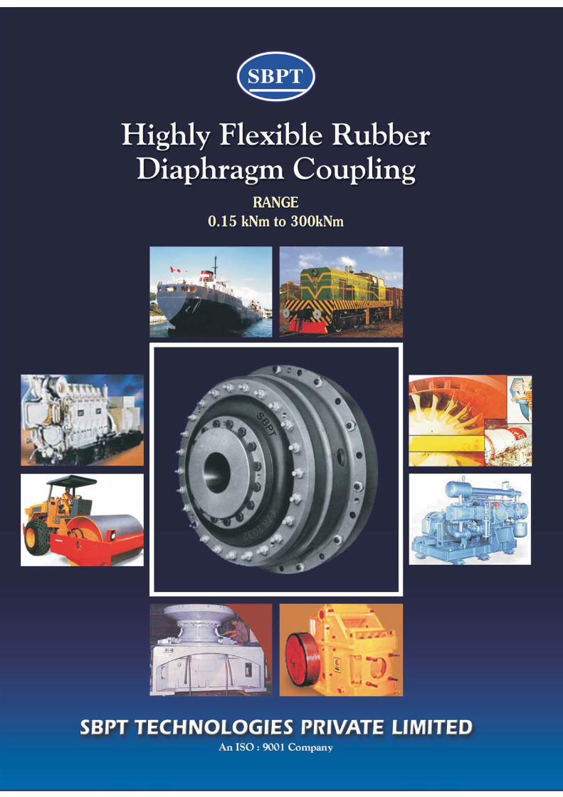
The SBPT highly flexible Diaphragm Coupling is a fabric-reinforced rubber coupling with multi-directional flexibility. The use of synthetic fiber guarantees high strength. The coupling is used inapplications where two approximately co-axially rotating machines have to be flexibly connected suchas diesel engine and electric motor-driven equipment including marine propulsion systems, two-bearing generators, compressors, pumps, fans, crushers, ball and rolling mills.
Sizes available to transmit up to 300 kNm of torque
Allows 3 25 degree torsional deflection
Rupture torque 7 9 times of nominal torque
Progressive dynamic torsional stiffness . . . increases with increasing torque
Dampens torsional vibrations
Provides precise systems tuning... several torsional stiffnesses are available for each
coupling size.
Accommodates misalignment.
Absorbs shocks and attenuates noise.
Rubber-in-shear design serves as a mechanical fuse to protect equipment from
excessive torque overload
Requires no lubrication / maintenance
Available blind assembly and in single diaphragm designs
Custom built designs available
Land or sea, stationary or mobile, you will find SBPT Diaphragm Coupling powering a wide range ofapplication such as Marine, Road Construction, Mining, Compressor, Locomotives and otherequipments. No matter what application is, there is a reliable, SBPT Diaphragm Coupling ready tooperate.
�
�
�
�
�
�
�
�
�
�
�
�

Emergency drive is applicable for Marine application only.
FIG. -1
118 WITHOUTEMERGENCY DRIVE
130 WITHOUTEMERGENCY DRIVE
148 WITHOUTEMERGENCY DRIVE
111 WITHOUTEMERGENCY DRIVE
Loco
118 WITHEMERGENCY DRIVE
130 WITHEMERGENCY DRIVE
148 WITHEMERGENCY DRIVE
111 WITHEMERGENCY DRIVE
Blind Assembly
FIG. -2Parts1) Hub2) Flanged Casing3) Intermediate Ring4) Inner Clamping Ring5) Rubber Diaphragms6) Outer Clamping Ring7) Inner Clamping Screw8) Inner screw9) Outer Clamping Screw10) Adapter Ring
SBPT DIAPHRAGM COUPLING : SERIES AVAILABLE
CHARACTERISTIC CURVE

SELECTION1. Select the Service Factor S based on
application from the Table.2. Calculate Torque ( T ) in kNm
T = KW x 9550 x S 1000 RPMor T = HP x 716.2 x 9.86 x S 1000 RPM
3. Select coupling size having Tnom > T4. Check for maximum bore limit. If the
maximum bore is exceeded, move to highercoupling size.
5. Check the RPM and select casing material.
//
Guideline for Typical ServiceFactor ‘S’
LOADCLASSIFICATION
SERVICEFACTOR S
Continuous service andlow running load variation
Torque loading variesduring operation
For medium shockloading or lightreversing drive
For heavy shockloading / reversing drive
1.20
1.50
1.75
2.00
CONVERSION FACTORS
1. Torque : (S.I. Unit - Nm)1 kNm = 1000 Nm = 738 lb ft.; 1 Nm = 0.1015 kpm = 10.15 kpcm.
2. Force : (S.I. Unit - Newton)1N = 0.102 kp. = 0.225 lb.
3. Moment of Inertia : (S.I. Unit - kgm )
1 kgm = 8.85 lb in sec = 10.15 kpcms4. Power : (S.I. Unit - Watt)
1 W = 0.00134 HP; 1 PS = 0.986 HP5. Stiffness : (S.I. Unit - N/m)
1 N/m = 101.714 kp/m = 0.1017 kp/mm = 0.00571 lb/in6. Torsional stiffness : (S.I. Unit - Nm/rad)
1 Nm/rad = 10.15 kpcm/rad = 0.1015 kpm/rad = 8.85 lb in/rad
2
2 2 2
WE ALSO INDEPENDENTLY DEVELOPED REPLACEMENTVULKAN EZ / EZS / EZR RUBBER ELEMENTS GUARANTEED TOPROVIDE EXCELLENT PERFORMANCE AT HIGHLYATTRACTIVEPRICES

Technical Data
Tn- NOMINAL TORQUE
Tmax - MAXIMUM TORQUE
Tv - VIBRATORY TORQUE
ANGULAR DISPLACEMENT
- RELATIVE DAMPING
The maximum torque capacity of a coupling on a continuous basis.
The maximum torque capacity of a coupling (3 x Tn) during start-up, shutdown, shock loads, and transientconditions.
The allowable vibratory torque capacity of a coupling at ambient coupling temperatures up to 60C.
The angular misalignment capacity of a Diaphragm Coupling is 1.0 degrees.
The relative damping of a coupling element is the ratio of the damping energy converted to heat during a vibrationcycle to the flexible strain energy of the element. The influence of vibratory amplitude and frequency on the relativedamping factor can be neglected. Note: The superscript mark ' signifies the value has been derated; e.g., D ', P ', etc.
= 1.13 for all sizes
NOTE : * COUPLINGS ARE ALSO AVAILABLE WITH DIFFERENT TORSIONAL STIFFNESS VALUES.
* For single Diaphragm Coupling - Torque and Dynamic Torsional Stifness values are Half.
x
�
�
�R L
For Dimension : Please consult technical detail of SB / EZ type Diaphragm Coupling forSeries 100 , 110 & 140.
45 S 0.55 1.65 0.22 23.0 4600 3000 3.5 1.0 18 24 15 27 40.5 59
50 S 0.60 1.80 0.24 21.0 4000 2600 3.5 1.0 18 24 20 28 44 61
51 S 0.65 1.95 0.26 20.0 4000 2600 4.0 1.25 18 25 21 30 48 66
55 S 0.75 2.25 0.30 24.0 4000 2600 4.0 1.25 18 25 18 36 60 90
61 S 1.0 3 0.40 13.0 3550 2300 4.5 1.5 34 52 48 85 127 188
65 S 1.4 4.2 0.56 16.5 3500 2275 4.5 1.5 34 52 57 101 147 216
71 S 1.7 5.1 0.68 15.0 3050 2000 5.0 1.7 64 96 91 135 190 280
80 S 2.3 6.9 0.92 18.0 3050 2000 5.0 1.7 64 96 105 156 254 346
86 S 3.0 9.0 1.20 12.5 2600 1700 6.0 2.0 90 96 163 248 349 537
95 S 4.2 12.6 1.68 15.0 2600 1700 6.0 2.0 90 96 180 301 445 624
102 S 5.0 15.0 2.00 11.0 2250 1475 7.0 2.3 150 241 322 450 649 870
115 S 7.0 21.3 2.80 15.0 2250 1475 7.0 2.3 150 241 334 608 880 1158
121 S 8.87 26.6 3.55 12.0 1950 1275 7.5 2.5 140 180 552 777 1106 1398
135 S 12.0 36.0 4.80 14.5 1950 1275 7.5 2.5 140 180 602 914 1366 1830
141 S 14.8 44.4 5.92 12.0 1675 1100 8.0 3.0 215 275 770 1376 2180 2996
165 S 20.2 60.6 8.08 14.5 1675 1100 8.0 3.0 215 275 884 1978 3096 4198
171 S 25.0 75.0 10.00 14.5 1500 950 9.2 3.6 305 315 1144 1726 2531 3518
195 S 34.5 103.5 13.80 18.0 1500 950 9.2 3.6 305 315 1214 2178 3648 5086
201 S 44.5 133.5 17.80 14.5 1200 800 10.0 4.2 270 365 2118 3484 5544 8122
230 S 54.2 162.6 21.68 16.0 1200 800 10.0 4.2 270 365 2268 4278 6763 10210
235 S 69.0 207.0 27.60 18.5 1200 800 10.0 4.2 270 365 2802 5626 9061 13870
275 S 105.0 315.0 42.00 18.0 1050 700 11.0 4.6 335 440 3856 7160 11651 18183
310 S 177.5 532.5 71.0 13.5 850 550 13.0 5.5 1010 1460 9660 16574 25110 35678
320 S 236.0 708.0 94.4 15.0 850 550 13.0 5.5 1010 1460 10744 21887 34840 47400
360 S 301.0 903.0 120.40 18.0 850 550 13.0 5.5 1010 13970 14040 26330 42510 65930
SIZE
SB /
EZ
PermissibleValues
StaticTorsi-onalangle
at
TnomIn
degree.
PermissibleMaximum
SpeedRPM
N
PermissibleDisplacement
DeflectionStiffnessKp/mm.
Dynamic Torsional Stiffness (X1000)in kpcm / rad
Nominal
Torque
kNm
Tn
Max.Torque
KNmTmax
Vib.Torque
KNmTv
CSCasing
CICasing
Axial
mm.
Ka
Radialmm.Kr
AxialCa
Radial
Cr
C
at
25%
Tdyn C
at
50%
tdynC
at
75%
tdyn C
At
1`00%
Tdyn


4
2574 4318