introduction mechanical vibration and shock are present in
TRANSCRIPT

51
INTRODUCTION
In one extreme, the vibration environment may consist oflow-level seismic disturbances present everywhere on earth,which present operating problems to highly sensitive itemssuch as delicate optical equipment. When other disturbancesare superimposed on the seismic disturbances, a wide range of precision equipment is adversely affected.
These other disturbances are caused by such things as vehicular and foot traffic, passing trains, air conditioning systems, and nearby rotating and reciprocating machinery.They cause resolution problems in electron microscopes, disturb other optical systems, cause surface finish problemson precision grinders and jig borers, and hamper delicatework on microcircuitry.
Another concept is the detrimental effect of vibrating internal components of certain equipment such as motors,blowers, and fans in computers or similar systems. Thesecomponents transmit noise and vibration to the surroundingstructure resulting in fatigue, reduced reliability, and a“noisy” product.
When compared to stationary applications, vehicular installations subject equipment to much more severe shockand vibration. Vibration from a propulsion engine is presentin air, sea and road vehicles as well as shock and vibrationeffects from the media in which they travel.
Such common phenomena as air turbulence and roughroads impart severe dynamic transients to the vehicles traveling on them. In addition to rough seas, military shipsare also subjected to very severe mechanical shock when they encounter near-miss air and underwater explosions in combat.
Vibration-control techniques in the form of shock andvibration isolators have been devised to provide dynamicprotection to all types of equipment.
In discussing vibration protection, it is useful to identify the three basic elements of dynamic systems:
1. The equipment (component, machine motor, instrument, part, etc. ..);
2. The support structure (floor, baseplate, concrete foundation, etc. ..); and
3. The resilient member referred to as an isolator or mount(rubber pad, air column, spring, etc.) which is interposedbetween the equipment and the support structure.
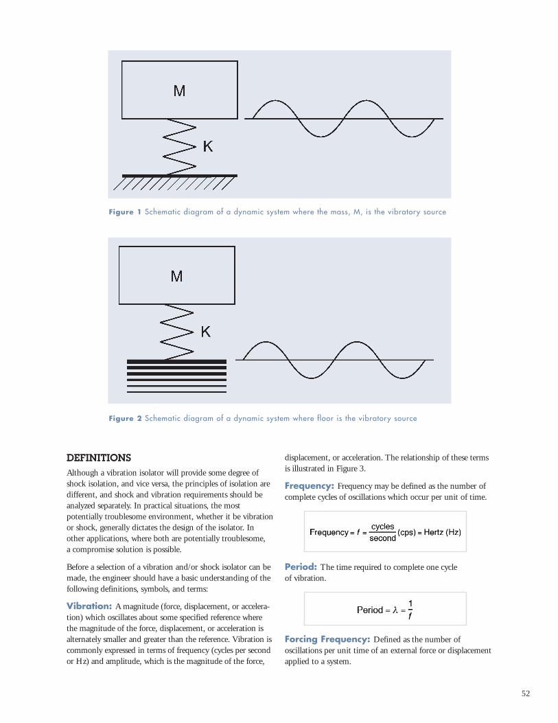
If the equipment is the source of the vibration and/or shock,the purpose of the isolator is to reduce the force transmittedfrom the equipment to the support structure. The directionof force transmission is from the equipment to the supportstructure. This is illustrated in Figure 1, where M representsthe mass of a motor which is the vibrating source, and K,which is located between the motor and the support struc-ture, represents the isolator.
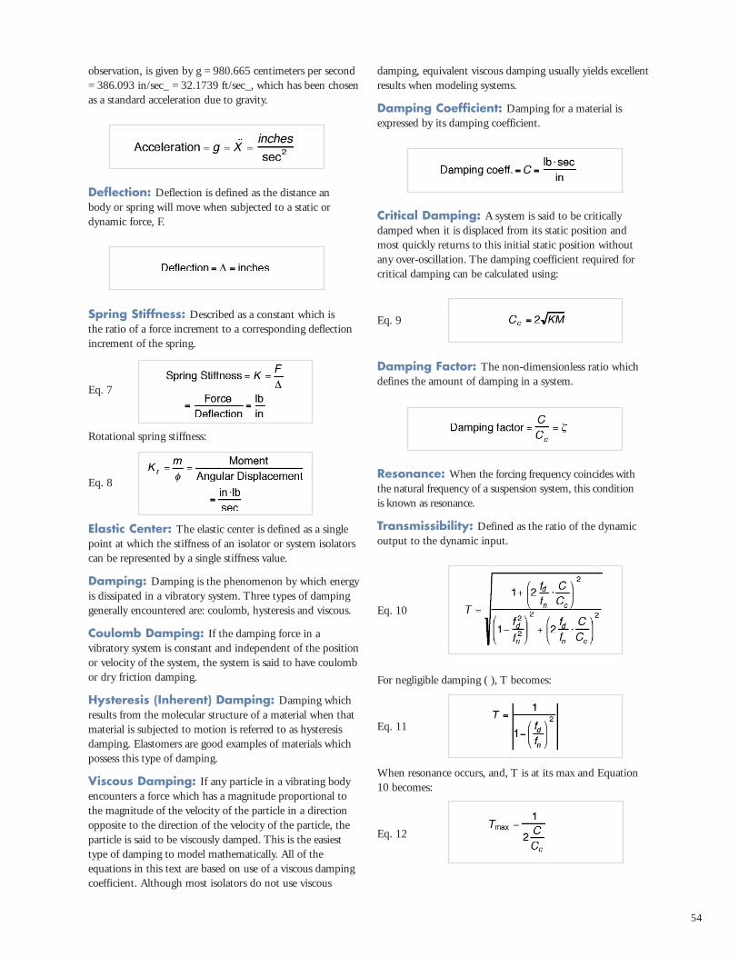
If the support structure is the source of the vibration and/orshock, the purpose of the isolator is to reduce the dynamicdisturbance transmitted from the support structure to theequipment. The direction of motion transmission is fromthe support structure to the equipment. This occurs, forinstance, in protecting delicate measuring instruments fromvibrating floors. This condition is illustrated in Figure 2,where M represents the mass of a delicate measuring instru-ment which is protected from vibrating floor by an isolatorsignified as K.
In either case, the principle of isolation is the same. The isolator, being a resilient element, stores the incoming energy at a time interval which affords a reduction of thedisturbance to the equipment or support structure.
The purpose of this Design Guide is to aid the designengineer in selecting the proper isolator to reduce theamount of vibration and/or shock that is transmitted to or from equipment.
Mechanical vibration and shock are present in varying
degrees in virtually all locations where equipment and people
function. The adverse effect of these disturbances can range
from negligible to catastrophic depending on the severity of
the disturbance and the sensitivity of the equipment.
52
DEFINITIONSAlthough a vibration isolator will provide some degree ofshock isolation, and vice versa, the principles of isolation aredifferent, and shock and vibration requirements should beanalyzed separately. In practical situations, the most potentially troublesome environment, whether it be vibrationor shock, generally dictates the design of the isolator. Inother applications, where both are potentially troublesome, a compromise solution is possible.
Before a selection of a vibration and/or shock isolator can bemade, the engineer should have a basic understanding of thefollowing definitions, symbols, and terms:
Vibration: A magnitude (force, displacement, or accelera-tion) which oscillates about some specified reference wherethe magnitude of the force, displacement, or acceleration isalternately smaller and greater than the reference. Vibration iscommonly expressed in terms of frequency (cycles per secondor Hz) and amplitude, which is the magnitude of the force,
displacement, or acceleration. The relationship of these termsis illustrated in Figure 3.
Frequency: Frequency may be defined as the number ofcomplete cycles of oscillations which occur per unit of time.
Period: The time required to complete one cycle of vibration.
Forcing Frequency: Defined as the number of oscillations per unit time of an external force or displacementapplied to a system.
Figure 1 Schematic diagram of a dynamic system where the mass, M, is the vibratory source
Figure 2 Schematic diagram of a dynamic system where floor is the vibratory source

53
Natural Frequency: Natural frequency may be defined as the number of oscillations that a system will carry out in unit time if displaced from it equilibrium position and allowed to vibrate freely. (See Figure 3)
Eq. 1
Eq. 2
Eq. 3
Natural frequency in terms of static deflection:
Eq. 4
Also, natural frequency for torsional vibration:
Eq. 5
Equations 1 through 5 all neglect the effects of damping.When damping is considered, Equation 2 becomes:
Eq. 6
Amplitude: The amplitude of a harmonic vibration such as displacement, velocity, or acceleration is the zero topeak value corresponding to the maximum magnitude of aharmonic vibration time-history. (See Figure 3.)
Displacement: Displacement is a vector quantity thatspecifies the change of the position of a body or particle andis usually measured from the mean position or equilibriumposition. In general it can be represented by a translation orrotation vector or both. (See Figure 3)
Velocity: Velocity is a vector that specifies the time ratechange of displacement with respect to a frame of reference.
Acceleration: Acceleration is a vector that specifies thetime rate of change of velocity with respect to a frame of reference. The acceleration produced by the force of gravity,which varies with the latitude and elevation of the point of
Figure 3 Schematic of oscillating spring mass system and graphical representation of vibratory responses
54
observation, is given by g = 980.665 centimeters per second= 386.093 in/sec_ = 32.1739 ft/sec_, which has been chosenas a standard acceleration due to gravity.
Deflection: Deflection is defined as the distance an body or spring will move when subjected to a static ordynamic force, F.
Spring Stiffness: Described as a constant which is the ratio of a force increment to a corresponding deflectionincrement of the spring.
Eq. 7
Rotational spring stiffness:
Eq. 8
Elastic Center: The elastic center is defined as a singlepoint at which the stiffness of an isolator or system isolatorscan be represented by a single stiffness value.
Damping: Damping is the phenomenon by which energyis dissipated in a vibratory system. Three types of dampinggenerally encountered are: coulomb, hysteresis and viscous.
Coulomb Damping: If the damping force in a vibratory system is constant and independent of the positionor velocity of the system, the system is said to have coulombor dry friction damping.
Hysteresis (Inherent) Damping: Damping whichresults from the molecular structure of a material when thatmaterial is subjected to motion is referred to as hysteresisdamping. Elastomers are good examples of materials whichpossess this type of damping.
Viscous Damping: If any particle in a vibrating bodyencounters a force which has a magnitude proportional tothe magnitude of the velocity of the particle in a directionopposite to the direction of the velocity of the particle, theparticle is said to be viscously damped. This is the easiesttype of damping to model mathematically. All of the equations in this text are based on use of a viscous dampingcoefficient. Although most isolators do not use viscous
damping, equivalent viscous damping usually yields excellentresults when modeling systems.
Damping Coefficient: Damping for a material isexpressed by its damping coefficient.
Critical Damping: A system is said to be criticallydamped when it is displaced from its static position andmost quickly returns to this initial static position withoutany over-oscillation. The damping coefficient required forcritical damping can be calculated using:
Eq. 9
Damping Factor: The non-dimensionless ratio whichdefines the amount of damping in a system.
Resonance: When the forcing frequency coincides withthe natural frequency of a suspension system, this condition is known as resonance.
Transmissibility: Defined as the ratio of the dynamicoutput to the dynamic input.
Eq. 10
For negligible damping ( ), T becomes:
Eq. 11
When resonance occurs, and, T is at its max and Equation10 becomes:
Eq. 12

55
Shock: Defined as a motion in which there is a sharp,nearly sudden change in velocity. Examples of this are a hammer blow on a anvil or a package falling to the ground.Shock may be expressed mathematically as a motion inwhich the velocity changes very suddenly.
Shock Pulse: Shock pulse is a primary disturbance characterized by a rise and decay of acceleration from a constant value in a very short period of time. Shock pulsesare normally displayed graphically as acceleration vs. timecurves. See Figure 11 for examples of typical curves.
Shock Transmission: Shock transmitted to the object subjected to the shock. This can be calculated with the following equation:
Eq. 13
In this equation, V represents an instantaneous velocityshock. Most shock inputs can be approximated by an instan-taneous velocity shock. See shock isolation section startingon page X for more detail.
The associated dynamic linear deflection of an isolator undershock can be determined by the use of the following equation:
Eq. 14
DESIGN CONSIDERATIONSVertical Vibration: In the general introduction of thisGuide, it was pointed out that vibration and shock can havegross detrimental effects on the performance and reliability of a particular product. The vibration which a unit transmitsto a supporting structure or the vibration which a unit feelswhen it is being excited by a vibrating structure can bereduced or attenuated by an isolator if properly selected.Referring to the following discussion of how an isolator functions, the design example section of this Guide containsproblem solutions which use the equations and graphs presented in this section.
The function of an isolator may be best understood by firstreducing it to its simplest form, as illustrated in Figure 4.The system of Figure 4 includes a rigid mass M supported bya spring K and constrained by guides to move only in verticaltranslation without rotation about a vertical axis. A damperC is arranged in parallel with the spring between the supportand the mass. The mounted equipment is simulated by themass while the spring and damper taken together simulatethe elasticity and damping of the conventional isolator. Thesystem shown in Figure 4 is said to be a single-degree-of-free-dom system because its configuration at any time may bespecified by a single coordinate; e.g., by the height of themass M with respect to the fixed support.
Isolation is attained primarily by maintaining the proper relationship between the disturbing frequency and the system’s natural frequency. The characteristics of the isolatorinclude its natural frequency, or more properly, the naturalfrequency of the system consisting of isolator and mountedequipment. In general, a system has a natural frequency foreach degree of freedom; the single-degree-of-freedom systemillustrated in Figure 4 thus has one natural frequency. Theexpression for the damped natural frequency of the systemillustrated in Figure 4, expressed in cycles per second, is:
(Eq. 6)
A critical damped system returns without oscillation to equi-librium if displaced; it has no natural frequency of oscilla-tion, as indicated by the substitution of C=Cc in Equation 6.
In most circumstances the value of the damping coefficient is relatively small. The influence of damping on the naturalfrequency may then be neglected. Setting the damping coef-ficient C equal to zero, the system becomes an undampedsingle-degree-of-freedom system, and the undamped naturalfrequency given by:
(Eq. 2)
This expression is sufficiently accurate for calculating theactual natural frequency in most instances.
The concept of static deflection often is used to define thecharacteristics of an isolator. Static deflection is the deflectionof the isolator under the static or deadweight load of themounted equipment. Referring to Equation 2 and substitut-ing in/sec2, , the following expression is obtained for naturalfrequency in terms of static deflection:
(Eq. 4)Figure 4 Schematic of the simplest form of an isolator, a spring, K, and a viscous damper,C, supporting the equipment mass, M.

56
A graphic portrayal of Equation 4 is given in Figure 5. It thusappears possible to determine the natural frequency of a single-degree-of-freedom system by measuring only the static deflec-tion. This is true with certain qualification. First, the springmust be linear — its force vs. deflection curve must be astraight line. Second, the resilient material must have the sametype of elasticity under both static and dynamic conditions.
Metallic springs generally meet this latter requirement, butmany organic materials used in isolators do not. The dynam-ic modulus of elasticity of these materials is higher than thestatic modulus; the natural frequency of the isolator is thussomewhat greater than that calculated on the basis of staticdeflection alone.
Dynamic stiffness may be obtained indirectly by determiningthe natural frequency when the isolator is vibrated with a known load and calculating the dynamic stiffness fromEquation 2. The various organic materials have certain peculiarities with respect to dynamic stiffness which will be discussed later in connection with the specific materials.
Effectiveness of isolators in reducing vibration is indicated by the transmissibility of the system. Figure 6 illustrates atypical transmissibility curve for an equipment of weight W supported on an isolator with stiffness K and dampingcoefficient C which is subjected to a vibration disturbance of frequency fd. When the system is excited at its natural frequency, the system will be in resonance and the disturbance forces will be amplified rather thanreduced.Therefore, it is very desirable to select the properisolator so that its natural frequency will be excited as little as possible in service and will not coincide with any criticalfrequencies of the equipment.
Referring to Figure 6, it can be seen that when the ratio ofthe disturbing frequency fd over the natural frequency fn isless than or 1.4, the transmissibility is greater than 1, or theequipment experiences amplification of the input. Simplyexpressed, when:
theoretically, isolation begins when:
Also it can be seen that when:
the mounted unit is said to be isolated; i.e., the output Xo is less than input Xi.
Damping: The majority of isolators possess damping in varying degrees. A convenient reference illustrating damping factor C/Cc for various materials is shown in Table1. Damping is advantageous when the mounted system isoperating at or near its natural frequency because it helps to reduce transmissibility. For example, consider an internalcombustion engine mounted on steel springs which possessvery little damping (see Table 1). Upon start up of the engineand as the engine RPM increases, the disturbing frequency of the engine will at some point correspond with the naturalfrequency of the spring-mass system. With light damping,
Figure 5 Relation of natural frequency andstatic deflection of a linear, single-degree-of-freedom system.
Figure 6 Typical transmissibility curve foran isolated system where fd = disturbancefrequency and fn = isolation system naturalfrequency.

57
the buildup of forces from the engine to the support will bevery large; that is, transmissibility will be very high. If theidle RPM of the engine falls in the range of the natural frequency of the spring-mass system, serious damage mayresult to the engine or to the support chassis. If, on the otherhand, the designer selects an elastomeric isolator which pos-sesses a higher degree of damping, amplification at resonancewould be much less.
The relationship between a highly damped and a lightlydamped system is illustrated in Figure 8. This figure showsthat as damping is increased, isolation efficiency is somewhatreduced in the isolation region. While high values of dampingcause significant reduction of transmissibility at resonance, its effect in the isolation region is only a small increase transmissibility.
A family of curves which relate fn, fd, transmissibility anddamping are shown in Figure 8. This family of curves wasderived by use of Equation 10.
Horizontal Vibration: When an isolation system isexcited horizontally, two natural frequencies result if the center of gravity of the unit is not in line with the elasticcenter of the isolators. A typical transmissibility curve illustrating this horizontal vibration output is illustrated in Figure 9. The two natural frequencies which are involvedinclude a lower mode wherein the equipment rocks about a point well below the elastic center of the isolators and ahigher mode where the equipment oscillates about a point in the vicinity of the center of gravity. Two other natural frequencies will occur if the equipment is rotated 90 degreesin the horizontal plane with respect to the exciting force.
Table 1 Damping factors for materials commonly used for isolators
Steel Spring 0.005 100Elastomers: - -
Natural Rubber 0.05 10Neoprene 0.05 10Butyl 0.12 4.0Barry Hi Damp 0.15 3.5Barry LT 0.11 4.5Barry Universal 0.08 6.0
Friction Damped Springs 0.33 1.5Metal Mesh 0.12 4.0Air Damping 0.17 3.0Felt and Cork 0.06 8.0
Material Approx Damping
FactorC/Cc
Tmax(approx.)
Figure 7 Typical transmissibility curves forhighly and lightly damped systems.
Figure 8 Family of transmissibility curvesfor a single degree of freedom system.

58
Figure 10 can be used to determine the approximate frequencies of these modes as a function of spring stiffnessand equipment dimensions. These curves assume that theequipment is solid, of uniform mass, and that the isolatorsare attached at the extreme corners. Under horizontal excitation the equipment may be made to translate only bylining up the center of gravity of the equipment with theelastic center of the isolators instead of installing the isolatorsat the bottom corners of the equipment. In this case, Figure10 may be applied by letting H/W = 0, which results in onlyone mode of vibration, that of translation. A second modecan only be excited by torsional excitation.
Structure-Borne Noise: The demand on equipmenttoday is to maximize its output which generally requiresfaster operation and more complex mechanical motions. As a result, noise is sometimes generated. High frequencydisturbances are excited because the moving componentswithin the equipment impose vibratory inputs to the internalstructures. These vibrations are amplified and structure-borne noise is encountered. Complete equipments bolted totheir support foundations also cause similar noisy conditions.
An effective and low cost means of alleviating structure-borne noise problems is to physically separate the solid struc-tures and interpose a resilient material between them. In thismanner a mechanical attachment is provided but the resilientmedia prevents the vibration forces from being transmittedand structure-borne noise is substantially reduced.
Elastomeric materials are generally best suited for structure-borne noise reduction. They exhibit the desirablecharacteristics of shape flexibility and inherent damping toavoid spring-like response which might produce violent resonances at critical frequencies. They afford high frequencyisolation. Many isolators suitable for attenuation of structure-borne noise problems are available from Barry and these areoutlined in the Selection Guide, Section 6.
Shock: Shock is normally classified as a transient phenomenon, while a typical vibration input is classified as a steady-state phenomenon. A shock input pulse is normallydescribed by its peak amplitude A expressed in g’s, by itsduration t normally expressed in milliseconds, and its overallshape, which can take such forms as half-sine, triangular,(initial peak sawtooth, symmetrical and terminal peak sawtooth), versed sine, rectangular, and the form most likelyto occur in nature, a more or less random shaped complexwaveform force and acceleration impulse as shown in Figure 11.
Since there are many types of shock pulses encountered in nature, there are many types of shock tests specified fortesting a piece of equipment. The different shock tests arenormally associated with the environment that the equip-ment will encounter during its lifetime. Equipment installedin aircraft is normally tested on a free-fall shock machinewhich will generate either a half-sine or terminal peak sawtooth form. A typical test is an 11-millisecond half-sinewaveform with a peak acceleration of 15 g’s. For componentsin some areas of missiles where large shock pulses will be feltdue to explosive separation of stages, a 6-millisecond saw-tooth at 100 g’s may be specified. If a piece of equipment is going on board a Navy vessel, the normal test will be thehammer blow specified in MIL-S-901, which exhibits avelocity shock of approximately 120 in./sec. Shipping containers are normally tested by dropping the container on a concrete floor, or by suspending it by some suitable support mechanism and letting it swing against a concreteabutment. Other tests pertaining to shipment are edge andcorner drops from various drop heights. All of these tests
Figure 9 Typical transmissibility curve forhorizontal vibration inputs.
Figure 10 Horizontal natural frequencies of a homogeneous solid mounted on linear,undamped springs at edge of mass.

59
mentioned attempt to simulate the shock pulse which will beencountered in the normal environment of the equipment.These are generally called out by the specific contractualrequirements either in a specification or in a work requirement.
The isolation of shock inputs is considerably different fromthat of a vibration input. The shock isolator is characterizedas a storage device wherein the input energy, usually with avery steep wave front, is instantaneously absorbed by the isolator. This energy is stored in the isolator and released atthe natural frequency of the spring-mass system.
The most common procedure for predicting shock isolationis a mathematical approach utilizing equations in Figure 11,for determining the velocity, and Equation 13, for calculatingtransmitted accelerations.
Another means is through the use of shock transmissibilitycurves. Shock transmissibility curves are not included in thisGuide, but are included in a technical paper published byBarry Controls titled Passive Shock Isolation. Please call 1-800-BARRY MA for a copy of this paper.
These two methods are valid for solving shock problems provided that the shock pulse is thoroughly defined, and that the isolation system responds in its linear region.
Nonlinear Isolators: The preceding discussion ofvibration and shock isolation presumes that the isolator islinear, the force-deflection curve for the isolator is a straightline. This simplified analysis is entirely adequate for manypurposes. In the isolation of steady-state vibration, displacement amplitude is usually small, and nonlinearity of the isolator tends to be unimportant except where deflec-tion resulting from the static load is relatively great. In the
isolation of shock, nonlinearity tends to be more importantbecause large deflections prevail. The degree of isolation maythen be substantially affected by the ability, or lack thereof,of the isolator to accommodate the required deflection.
In many applications of shock isolation, sufficient space isnot available to allow for full travel of a linear isolator.Therefore, a nonlinear isolator is necessary. There are twotypes of isolators that can be designed to help solve the problem of insufficient space.
The first solution is to make an isolator that gets stiffer asdeflection increases. This will limit the amount of motion,but will increase the G level imparted on the equipment.
The second is to use an isolator that is stiff at small deflection, but gets softer at higher deflections. This isreferred to as a buckling isolator, and is shown in Figure 12.This allows the isolator to store more energy in the sameamount of deflection. (A shock isolator is basically an energystorage device; it stores high g-level, short-duration shockand releases them as low g-level, longer-duration shocks.)
ISOLATORS AND MATERIALSIsolators are made from a wide variety of resilient media having diverse characteristics. Each type of isolator has characteristic properties and is particularly suited to certainspecialized applications. To make the best use of available isolators, the designer should understand the basic propertiesof each type. He should also be familiar with the require-ments for isolators for various types of equipment, as indicated in the preceding discussions. Keep in mind that not all isolators can be manufactured out of any material.
Figure 11 Idealized forms of shock excitation and the velocity change, V, associated with each shock pulse
Force Impulse
Half-Sine Acceleration
Acceleration Impulse
Rectangular Acceleration
Velocity Shock
Triangular Acceleration
Free-Fall Impact
Versed-Sine Acceleration

60
Elastomeric Isolators: Elastomers are well adapted for use in shock isolators because of their high energy storagecapacity and because the convenience of molding to any shape makes it possible to attain the linearity or nonlinearityrequired for adequate shock isolation.
Most elastomeric isolators cannot be constantly subjected to large strains. An isolator with a large static deflection maygive satisfactory performance temporarily but it tends to drift or creep excessively over a relatively short period oftime. Opinions on maximum permissible static strain varywidely, but it may be taken as a conservative limitation thatelastomers should not be continuously strained more than 10 to 15% in compression, nor more than 25 to 50% inshear. These rules of thumb are often used to determine the maximum load capacity of a given isolator.
In spite of the limitations of elastomeric materials used in isolators, the overall advantages far outweigh the disadvan-tages and make elastomers the most highly desirable type ofresilient media for isolators.
With this type of isolator, the elastomer is strained in compression when the load is applied along “A” direction.Stiffness in any direction perpendicular to the “A” direction,
such as the “B” direction, is a function of the shear modulusof the elastomer, and tends to be relatively low comparedcompressive stiffness.
Springs: Metal springs can be used as vibration isolators.In some instances, these types of isolators work well.Frequently, the lack of damping in these type of isolatorsforces them to experience extremely violent resonances conditions (see “Damping” section and Figure 8).
Combination Spring-Friction Damper: To overcome the disadvantages of little or no damping in coilsprings, friction dampers can be designed in parallel with theload-carrying spring. These types of isolators are widely usedin practice. An example of this is illustrated in Figure 13.
In this construction, along the vertical axis a plastic damperslides along the walls of a cup housing, and the normal forceis provided by a radial damper spring. For horizontal damping, a central metal core which is directly attached onits top side to the equipment bears on the damper on its bottom side. The normal force is provided by the weight ofthe equipment, and damping results from the sliding duringhorizontal excitations. Transmissibility values of about 2 areexhibited by using this type of spring/damper combination.
Figure 12 Force vs. Deflection curves for some typical elastomeric isolators
With this type of isolator, the elastomer isstrained in compression when the load isapplied along “A” direction. Stiffness inany direction perpendicular to the “A”direction, such as the “B” direction, is afunction of the shear modulus of the elas-tomer, and tends to be relatively low com-pared compressive stiffness.
This isolator is symmetrical with respectto its central axis. The elastomer sectionsand cup shapes are designed such that thestiffness is approximately the same inevery direction. This is done by loadingequal amounts of elastomer in compres-sion in all directions. Also, the mounttends to exhibit stiffening after a certainrange of linear deflection.
This isolator supports the static load inthe “A” direction. When additional forceis applied in this direction, the cylindricalwalls of elastomer buckle. Buckling createsthe shape of curve “A”, which is veryeffective at attenuating shock forces.Forces in the B direction strain the wallsin shear.

61
Combination Springs with Air Damping:Another method of adding damping to a spring is by use of an air chamber with an orifice for metering the air flow.An example of this type of isolator is illustrated in Figure 14.In this construction the load-carrying spring is located withinthe confines of an elastomeric damping balloon. The airchamber is formed by closing the balloon with a cap whichcontains an orifice or the force flow metering. Under dynamic excitations the air in the balloon passes through a predetermined sized orifice by which damping is closelycontrolled. Transmissibilities generally under 4 result withthis type of design.
Air-damped springs have some specific advantages over seemingly similar friction damped designs with respect toisolating low-level inputs. Air damping, a form of viscousdamping, causes the damping forces to be reduced if theinput levels are reduced.
With friction damping, the friction force is constant. Inpractice, this means that the damping ratio is effectivelyincreased with the input levels are decreased. Referring toFigure 8, one can see increasing the damping ratio decreasesthe level of isolation. In summary, air damped isolators arebest suited for isolating low-level vibrations, while frictiondamped isolators are usually ideal for higher-level vibrations.
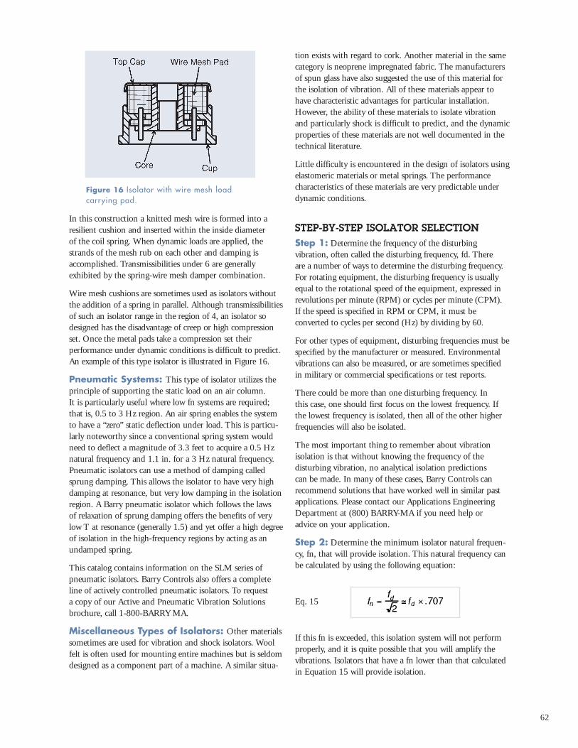
Combination Springs with Wire MeshDamping: For applications where all meal isolators aredesired because of temperature extremes or other environ-mental factors, damping can be added to a load carryingspring by use of metal mesh inserts Figure 15 illustrates this concept.
Table 2 Relative properties of elastomers used as the resilient media for isolators
Adhesion to Metal Excellent Excellent Good Very GoodTensile Strength Excellent Excellent Good ExcellentTear Resistance Good Good Fair GoodCompression Set Resistance Good Fair Fair GoodDamping Factor, C/Cc (approx.) 0.05 0.05 0.15 0.12Operating Temperature (max) 200F 200F 300F 200FStiffness Increase (approx.) @ -65F 10X 10X < 2X 2XOil Resistance Poor Good Fair FairOzone Resistance Poor Good Excellent FairResistance to Sunlight Aging Poor Very Good Excellent GoodResistance to Heat Aging Fair Good Excellent GoodCost Low Low High Moderate
Properties Natural Neoprene Hi-Damp ® Barry LT Rubber Silicone Compound
Figure 13 Isolator using friction dampedspring.
Figure 14 Isolator using air damped spring.Figure 15 Isolator using metal-mesh dampedspring.
62
In this construction a knitted mesh wire is formed into aresilient cushion and inserted within the inside diameter of the coil spring. When dynamic loads are applied, thestrands of the mesh rub on each other and damping isaccomplished. Transmissibilities under 6 are generally exhibited by the spring-wire mesh damper combination.
Wire mesh cushions are sometimes used as isolators withoutthe addition of a spring in parallel. Although transmissibilitiesof such an isolator range in the region of 4, an isolator sodesigned has the disadvantage of creep or high compressionset. Once the metal pads take a compression set their performance under dynamic conditions is difficult to predict. An example of this type isolator is illustrated in Figure 16.
Pneumatic Systems: This type of isolator utilizes theprinciple of supporting the static load on an air column. It is particularly useful where low fn systems are required;that is, 0.5 to 3 Hz region. An air spring enables the systemto have a “zero” static deflection under load. This is particu-larly noteworthy since a conventional spring system wouldneed to deflect a magnitude of 3.3 feet to acquire a 0.5 Hznatural frequency and 1.1 in. for a 3 Hz natural frequency.Pneumatic isolators can use a method of damping calledsprung damping. This allows the isolator to have very highdamping at resonance, but very low damping in the isolationregion. A Barry pneumatic isolator which follows the laws of relaxation of sprung damping offers the benefits of verylow T at resonance (generally 1.5) and yet offer a high degreeof isolation in the high-frequency regions by acting as anundamped spring.
This catalog contains information on the SLM series ofpneumatic isolators. Barry Controls also offers a completeline of actively controlled pneumatic isolators. To request a copy of our Active and Pneumatic Vibration Solutionsbrochure, call 1-800-BARRY MA.
Miscellaneous Types of Isolators: Other materialssometimes are used for vibration and shock isolators. Woolfelt is often used for mounting entire machines but is seldomdesigned as a component part of a machine. A similar situa-
tion exists with regard to cork. Another material in the samecategory is neoprene impregnated fabric. The manufacturers of spun glass have also suggested the use of this material forthe isolation of vibration. All of these materials appear tohave characteristic advantages for particular installation.However, the ability of these materials to isolate vibrationand particularly shock is difficult to predict, and the dynamicproperties of these materials are not well documented in thetechnical literature.
Little difficulty is encountered in the design of isolators usingelastomeric materials or metal springs. The performancecharacteristics of these materials are very predictable underdynamic conditions.
STEP-BY-STEP ISOLATOR SELECTIONStep 1: Determine the frequency of the disturbing vibration, often called the disturbing frequency, fd. There are a number of ways to determine the disturbing frequency.For rotating equipment, the disturbing frequency is usuallyequal to the rotational speed of the equipment, expressed inrevolutions per minute (RPM) or cycles per minute (CPM).If the speed is specified in RPM or CPM, it must be converted to cycles per second (Hz) by dividing by 60.
For other types of equipment, disturbing frequencies must bespecified by the manufacturer or measured. Environmentalvibrations can also be measured, or are sometimes specifiedin military or commercial specifications or test reports.
There could be more than one disturbing frequency. In this case, one should first focus on the lowest frequency. Ifthe lowest frequency is isolated, then all of the other higherfrequencies will also be isolated.
The most important thing to remember about vibration isolation is that without knowing the frequency of the disturbing vibration, no analytical isolation predictions can be made. In many of these cases, Barry Controls can recommend solutions that have worked well in similar pastapplications. Please contact our Applications EngineeringDepartment at (800) BARRY-MA if you need help or advice on your application.
Step 2: Determine the minimum isolator natural frequen-cy, fn, that will provide isolation. This natural frequency canbe calculated by using the following equation:
Eq. 15
If this fn is exceeded, this isolation system will not performproperly, and it is quite possible that you will amplify thevibrations. Isolators that have a fn lower than that calculatedin Equation 15 will provide isolation.
Figure 16 Isolator with wire mesh load carrying pad.
63
At this point, there will be many isolators that can beremoved from the list of possible selections. Our catalogclearly states the natural frequency range of each isolatorfamily in the main information block on the first page of each family. If any of the information is missing or unclear,please contact Barry Controls Applications Engineering at(800) BARRY-MA.
Step 3: Determine what isolator natural frequency willprovide the desired level of isolation. Step 2 has provided aquick way to determine which mounts provide isolation, butdoes not provide any information on the level of isolationthat will be achieved. Equation 11 can be used to calculatetransmissibility:
(Eq. 11)
Equation 11 can be used to calculate the transmissibility of aknown disturbing frequency through a mount with a knownnatural frequency. It can also be rearranged to the followingform:
Eq. 16
Equation 16 is valid only when fd/fn>1. This can be used to calculate the required natural frequency to achieve thedesired level of isolation of a particular disturbing frequency.
Step 4: Select the appropriate isolator for your application.Step 3 should reduce the list of possible isolators consider-ably, but there still may be more than one isolator that “qual-ifies.” One way to determine which is best suited is to lookunder the “Applications” heading on the first page of eachisolator family. If your application is not in this list, it doesnot necessarily mean that the isolator can’t be used, but theremay be a better choice.
The selection can also be narrowed down by looking at theenvironmental and dimensional data sections for each candidate isolator. Is the temperature range appropriate? Can the isolator fit in the required space? Is the mount capa-ble of supporting a load in the necessary direction? These aretypical questions than can be used to make a final selection.
If there is still more than one isolator that fits your application, or if you cannot find one that meets all of yourrequirements, please contact our Applications Engineeringdepartment at (800) BARRY-MA. We have expert engineersavailable to help make selections and answer questions aboutour products. If you have trouble dialing our “800” number,please call our main switchboard at (617) 787-1555.
DESIGN EXAMPLESThis section deals with the selection and application of vibration and shock isolators. For the proper selections ofisolators, it is desirable to obtain, where possible, pertinentinformation relating to the equipment, input and outputrequirements, and the general environment. Examples of the type of information or data required are:
Relating to the equipment:Weight.Dimensions.CG location.Number and location of isolators.Available space for isolators.Fragility level of the equipment.
Relating to the dynamic inputs and outputs:Level of vibration.Level of shock.Space limitations.
Relating to general environment:Temperature.Humidity.Salt spray.Corrosive atmosphere.Altitude.
All of the above information is not always readily availablenor is it always completely required in some applications.This will be further clarified in the following problem examples.
Example 1 - Vertical Vibration: A metal tumbling drum directly driven by a 1080 RPM motor is causing vibration disturbance to the floor on which it is mounted the drum, motor, and support base weighs 400 pounds. There are 4 mounting points for the isolators.The required isolation is 80%.
1. Determine fn of isolators required by using mathematical methods.
2. Determine static deflection of isolators by using (a)mathematical methods and (b) the static deflection vs.natural frequency curve in Figure 5.
3. Determine damping factor C/Cc to limit transmissibilityat resonance to 10 by using (a) mathematical methodsand (b) the transmissibility curve in Figure 8.
4. Determine the resilient media which could be used inthe isolator selected to provide the C/Cc required.
5. Determine the proper isolator to use for this application.

64
Solution:Known facts
Isolation required = 80%i.e. transmissibility = 0.20Disturbing frequency, fd = 1080 RPM
1. Using Equation 16, page 63:
2a. To find static deflection using mathematical approachuse Equation 4, page 53:
2b. To find static deflection using static deflection-naturalfrequency curve Figure 5, page 56. The intersection of fn of 7.35 Hz and the solid diagonal line yields a Dsof approximately 0.18 inches.
3a. To find C/Cc for a transmissibility of 10 by mathematical approach use Equation 12, page 54.Solving for C/Cc:
3b. To find C/Cc for a T of 10 by use of the transmissibilitycurve Figure 8, page 57. This curve shows that for atransmissibility of 10, C/Cc = 0.05.
4a. To find the correct resilient media which exhibits aC/Cc = 0.05 refer to Table 1, page 57. It can be seenthat natural rubber or neoprene would be the properselection.
5a. An isolator which best fits the above solved parametersis Barry Part No. 633A-100. Refer to the product information on pages 116-118 of this catalog to confirmthat this product meets all of the above needs.
Example 2 - Vertical and HorizontalVibration: An electronic transmitter which weighs 100 pounds, and has a height of 15", a width of 20" and a length of 30" is to be mounted in a ground vehicle whichimparts both vertical and horizontal vibratory inputs to the equipment. Since rough terrain is to be encountered a captive isolator is required. Four mounting points, one at each corner, are provided. It has been determined that the first critical frequency of the equipment is such that
an isolator with a 25 Hz vertical natural frequency would besatisfactory. Select an appropriate isolator and determine theapproximate horizontal rocking modes in the direction of theshort axis of the equipment which would be excited.
Solution:1. For vertical natural frequency:
Load per isolator = 100/4 = 25 lb.
Referring to a Barry isolator series designed for the rigors of vehicular applications, the 5200 series is suitable. From the load rating table in the productinformation section (18-30 pounds capacity for vehicu-lar applications) would handle the 25 pound load.
Using the load vs. natural frequency plots on page 192,the intersection of the 5220 curve for the 25 poundsload yields an fn of 24 Hz.
2. For horizontal rocking modes: The dynamic stiffnessratio of horizontal to vertical = 0.6 for the 5200 series.Referring to Figure 10, page 58 and assuming that massis homogeneous and isolators are at extreme corners, the following is found:
From the curves in Figure 10, page 58, the ratios offn/fVERT for first mode M1 is 0.7 and for secondmode, M2, is 1.7.
fn, 1st mode = 24 X 0.7 = 16.9 Hzfn, 2nd mode = 24 X 1.7 = 40.8 Hz
It is seen that this procedure lends a ready solution to determining the horizontal rocking modes based on the assumptions made. This solution is not exact but is generally satisfactory for practical purposes.
Example 3 - Shock: An electronic equipment is to be subjected to a 15G, 11 millisecond half-sine shock input.The equipment is mounted on a 10 Hz natural frequencyisolation system. Determine maximum shock transmissionand isolator deflection.
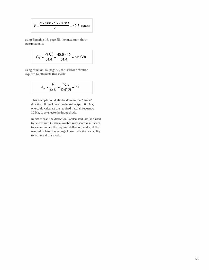
Solution:1. From Figure 11, page 59, the equation for shock
velocity change for a half-sine pulse is:
where: Ao=15Gto=0.011 secg=386 in/sec2
65
using Equation 13, page 55, the maximum shock transmission is:
using equation 14, page 55, the isolator deflection required to attenuate this shock:
This example could also be done in the “reverse” direction. If one knew the desired output, 6.6 G’s, one could calculate the required natural frequency, 10 Hz, to attenuate the input shock.
In either case, the deflection is calculated last, and usedto determine 1) if the allowable sway space is sufficientto accommodate the required deflection, and 2) if theselected isolator has enough linear deflection capabilityto withstand the shock.

66
Product‡ Page Load Natural All 1:1 Primary SpecialtyNumber Range (lbs) Frequency Attitude Stiffness Application
I SOLATOR PROPERT IES MATRIX
FrequencyLow: 10 Hz and belowMid: 10 Hz to 20 HzHigh: 20 Hz and above
‡This matrix includes all general-purpose isolators in this catalog. There may also be specialty isolators that weredesigned specifically for your application. Please refer to the “Specialty Isolators” Section on page X of this catalog.
Key:Primary ApplicationThis indicates the type of environment that this mount wasprimarily designed for. In mostcases, each series can be compatiblewith both shock and vibrationenvironments.
1:1 StiffnessRefers to axial-to-radial stiffness ratio.
All Attitude“Yes” means isolators can carrystatic load in any direction.* indicates base loading only.
Cupmounts X 0-1800 High Yes Yes Vibration Low-profile, ruggedS-Mounts X 0.3-45 Low No* No Vibration Air-dampedL-Mounts X 0.4-40 Low No* No Vibration Friction-dampedH-Mounts X 0.3-40 Low No* No Vibration Friction-dampedT-Mounts X 0-150 High Yes Yes Vibration Friction-dampedB-Mounts X 0-40 Mid/High Yes Yes Vibration Low-profile, bucklingME Series X 0-10 Mid No No Vib/Shock Low-profile, bucklingTTA Mounts X 0-15 Mid No Yes Shock BucklingTTB Mounts X 0-30 High No No Shock BucklingHTTA Mounts X 0-20 Mid No No Shock BucklingVHC Mounts X 0-145 Mid No No Shock BucklingCablemounts X 0-1800 Low/Mid Yes No Shock High-Temperature2K Mounts/Systems X 1-6000 Low/Mid No* No VIb/Shock Two-stage isolationGB530 Mounts X 0-1322 Low No No Vib/Shock Buckling, high capacityBarryflex (GBCO) Mounts X 0-40 Mid No No Shock BucklingStabl-Levl (SLM) X 0-19200 Low No* Yes Vibration Pneumatic mountLM and LMS Leveling Mounts X 0-13000 Mid No* No Vib/Shock Built-in Leveling633A Series X 0-260 Low/Mid No No VibrationIndustrial Machinery Mounts X 0-4400 Low/Mid No No Vibration30005 Series Neoprene Pads X 0-50 (psi) High No* No Vibration6300/6550 Series X 0-18 Mid/High Yes Yes Vibration Low-profileE21/E22 X 0-10 High Yes Yes Vibration Low-profile grommet5200 Series X 0-50 High Yes No Vibration Low-profile grommet6820 Series X 0-80 Mid Yes No Vibration Low-profile500 Series X 0-2700 Mid No Yes Vibration Rugged500SL Series X 0-920 Mid No No Vibration Low stiffness rationHR Series X 0-420 Mid No No Vibration High stiffness ratio22000 Series X 0-4500 Mid Yes Yes Vibration Low-cost, ruggedBarry-Bond Mounts X 0-2100 Mid/High No No Vibration Low-costIndustrial Conical Mounts X 0-1146 Mid No No Vibration RuggedCylindrical Stud-Mounts X 0-260 Low/Mid No No Vib/Shock Very Low-costW Series Ring and Bushing X 0-350 Mid Yes No VibrationBall Mounts X 0-9 Mid No No Vibration Light loads, low-costES Series Elastomer Springs X 0-14794 - No* No Shock Motion control