intraocular lens injector–induced stress on the corneal incisions during lens implantation
TRANSCRIPT
Intraocular Lens Injector–Induced Stress on the CornealIncisions During Lens Implantation
GUY KLEINMANN AND ITZHAK KLEINMANN
� PURPOSE: To describe a model for calculating inducedstress on corneal incisions during intraocular lens implan-tation, and to compare the nozzles of common injectorsusing 2 incision sizes.� DESIGN: Experimental study.� METHODS: A finite element calculation model wasdeveloped and used to compare 7 commercially availableinjectors in widespread clinical use. The injectors’ char-acteristics were measured and correlated for the stressthey induced for 2.4- or 2.2-mm corneal incisions.� RESULTS: Each injector created a different level ofstress on the corneal incision. The stress was highest atthe incision margins, and its level correlated with theinjector’s external circumference. The induced stress on2.2-mm incision margins was about 9% higher comparedto the induced stress on 2.4-mm incision margins.� CONCLUSIONS: A model for comparing stress inducedon corneal incisions during intraocular lens implantationby 7 injectors revealed different levels of induced stresson the incision margins. It is therefore recommendedthat the choice of injector be matched to the size of thecorneal incision. (Am J Ophthalmol 2014;-:-–-.� 2014 by Elsevier Inc. All rights reserved.)
IMPLANTATION OF A FOLDABLE INTRAOCULAR LENS
(IOL) during cataract surgery through a small incisionusually requires an injector system. There have been
several reports on damage to the IOLs or to the injectingsystem itself during the implantation process.1–7 Thereported damage includes marks or scratches,1,2 stressfractures,3 cracks,4 tear lines,5 and deposits,6,7 as well asbreaks and cracks of the cartridge nozzle.6 The effect ofimplanting an IOL through a narrow injector system onthe IOL and on the injector system was previously studied,8
but the effect of the choice of the injector system on thecorneal incision itself has not been investigated in depth.
In view of the current availability of high-quality pre-mium IOLs and patients’ demands for perfect visionfollowing the procedure, there is an ever-increasing need
Accepted for publication Mar 3, 2014.From the Department of Ophthalmology, Kaplan Medical Center,
Rehovot, Israel, affiliated to The School of Medicine, HebrewUniversity, Jerusalem, Israel.
Inquiries to Guy Kleinmann, Ophthalmology Department, KaplanMedical Center, POB 1, 76100 Rehovot, Israel; e-mail: [email protected]
0002-9394/$36.00http://dx.doi.org/10.1016/j.ajo.2014.03.001
� 2014 BY ELSEVIER INC.
for minimizing the incision size in cataract surgery in orderto reduce any surgically induced astigmatism. Smallercorneal incisions are also considered as being safer andmore watertight than larger ones.9 There are a variety ofinjector systems that are commercially available. Thosesystems differ in their principle of action and in several oftheir characteristics, such as external diameter and shapeof the nozzle, such that a different effect on the cornealincision can be expected from different injectors.We developed a finite element model for the comparison
of the induced stress on the corneal incision during IOLimplantation according to the characteristics of theinjector system. We then used the model to compare thelevels of stress induced by 7 popular injector systems and2 incision sizes; we present our findings.
METHODS
THIS WAS AN EXPERIMENTAL STUDY THAT DID NOT
require Institutional Review Board approval.Finite element analysis is a commonly used method for
structure behavior calculations (ie, displacements, reac-tions, internal loads and stresses) under various externalloading and environmental conditions. The finite elementanalysis assumptions for our model are: (1) the model issymmetrical through both its vertical and horizontal axes;(2) the results (expressed as gr/mm2) are used solely forcomparison; (3) no friction exists between the corneaand the injector’s outer surface; and (4) the cut lips ofthe cornea are fully attached to the injector’s outer surfaceas a result of the cornea’s extensive flexibility.The injectors that were included in the present study
were: Alcon C cartridge (Alcon, Fort Worth, Texas,USA), Alcon D cartridge (Alcon), Rayner R-INJ-04 softtip injector (Rayner Intraocular Lenses, East Sussex,England), Rayner R-INJ-04/18 soft tip injector (Rayner),Medicel NAVIJECT 2.2 (Medicel, Wolfhalden,Switzerland), Medicel VISCOJECT 1.8 (Medicel), andMDJ 2.2 (MDJ, La Monnerie Le Montel, France). Thenozzle shape of these injectors was either round or oval.Their inner and outer diameters at the tip were measuredwith a profile projector (H-14B NIKON, Tokyo, Japan)with a 203 magnification and a 1 micron resolution.The cornea structure in our model was represented as a
series of finite elements given the relevant geometry andmaterial properties. The cornea finite element model was
1ALL RIGHTS RESERVED.
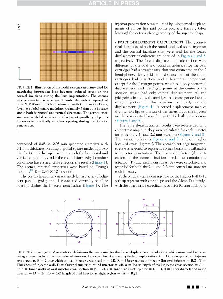
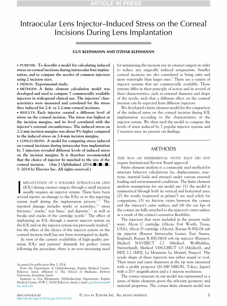
FIGURE 1. Illustration of the model’s cornea structure used forcalculating intraocular lens injectors induced stress on thecorneal incisions during the lens implantation. The corneawas represented as a series of finite elements composed of0.05 3 0.05-mm quadrant elements with 0.1 mm thickness,forming a global square model approximately 3 times the injectorsize in both horizontal and vertical directions. The corneal inci-sion was modeled as 2 series of adjacent parallel grid pointsdisconnected vertically to allow opening during the injectorpenetration.
composed of 0.05 3 0.05-mm quadrant elements with0.1 mm thickness, forming a global square model approxi-mately 3 times the injector size in both the horizontal andvertical directions. Under these conditions, edge boundaryconditions have a negligible effect on the results (Figure 1).The cornea material properties were based on Young’smodulus10: E ¼ 2.45 3 103 kg/mm2.
The cornea horizontal cut was modeled as 2 series of adja-cent parallel grid points disconnected vertically to allowopening during the injector penetration (Figure 1). The
FIGURE 2. The injectors’ geometrical definitions that were used forlating intraocular lens injector–induced stress on the corneal incisioncross section. B [ Outer width of oval injector cross section [ 2RThickness of injector wall. D [ Outer diameter of round injector2t. b [ Inner width of oval injector cross section [ B L 2t. r [ Iinjector [ D L 2t. Ro [ 1/2 length of oval injector straight regio
2 AMERICAN JOURNAL OF
injector penetration was simulated by using forced displace-ments of all cut lips grid points precisely forming (afterloading) the outer surface geometry of the injector shape.
� FORCE DISPLACEMENT CALCULATIONS: The geomet-rical definitions of both the round- and oval-shape injectorsand the corneal incisions that were used for the forceddisplacement calculations are detailed in Figures 2 and 3,respectively. The forced displacement calculations weredifferent for the oval and round cartridges, since the ovalcartridges had a straight area that was connected to the 2hemispheres. Every grid point displacement of the roundcartridges had a vertical and a horizontal component,except for the 2 margin points, which had only horizontaldisplacement, and the 2 grid points at the center of theincision, which had only vertical displacement. All thegrid points in the oval cartridges that corresponded to thestraight portion of the injectors had only verticaldisplacement (Figure 4). A forced displacement map ofthe incision lips as a result of the insertion of the injectornozzles was created for each injector for both incision sizes(Figures 5 and 6).The finite element analysis results were represented on a
color stress map and they were calculated for each injectorfor both the 2.4- and 2.2-mm incisions (Figures 7 and 8).The warmer colors in Figures 6 and 7 represent higherlevels of stress (kg/mm2). The cornea’s cut edge tangentialstress was selected to represent cornea behavior attributableto injector penetration. The extension factor (the ext-ension of the corneal incision needed to contain theinjector) (K) and maximum stress (Sy) were calculated andrecorded for both the 2.4- and 2.2-mm corneal incisions foreach injector.A theoretical equivalent injector for the Rayner R-INJ-18
soft tip injector with one shape and the Alcon D cartridgewith the other shape (specifically, oval for Rayner and round
the forced displacement calculations, which were used for calcu-s during the lens implantation. A[Outer length of oval injector. R [ Outer radius of injector (for oval injector [ B/2). T [[ 2R. a [ Inner length of oval injector cross section [ A Lnner radius of injector [ R L t. d [ Inner diameter of roundn [ (A L B)/2.
--- 2014OPHTHALMOLOGY
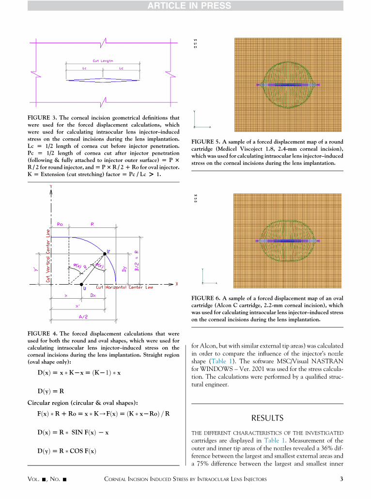
FIGURE 3. The corneal incision geometrical definitions thatwere used for the forced displacement calculations, whichwere used for calculating intraocular lens injector–inducedstress on the corneal incisions during the lens implantation.Lc [ 1/2 length of cornea cut before injector penetration.Pc [ 1/2 length of cornea cut after injector penetration(following & fully attached to injector outer surface) [ P 3R / 2 for round injector, and[ P3R / 2DRo for oval injector.K [ Extension (cut stretching) factor [ Pc / Lc > 1.
FIGURE 4. The forced displacement calculations that wereused for both the round and oval shapes, which were used forcalculating intraocular lens injector–induced stress on thecorneal incisions during the lens implantation. Straight region(oval shape only):
DðxÞ[ x � KLx[ ðKL1Þ � x
DðyÞ[R
Circular region (circular & oval shapes):
FðxÞ � RDRo[ x � K/FðxÞ[ ðK � xLRoÞ =R
DðxÞ[R � SIN FðxÞ L x
DðyÞ[R � COS FðxÞ
FIGURE 5. A sample of a forced displacement map of a roundcartridge (Medicel Viscoject 1.8, 2.4-mm corneal incision),which was used for calculating intraocular lens injector–inducedstress on the corneal incisions during the lens implantation.
FIGURE 6. A sample of a forced displacement map of an ovalcartridge (Alcon C cartridge, 2.2-mm corneal incision), whichwas used for calculating intraocular lens injector–induced stresson the corneal incisions during the lens implantation.
VOL. -, NO. - CORNEAL INCISION INDUCED STRESS
for Alcon, but with similar external tip areas) was calculatedin order to compare the influence of the injector’s nozzleshape (Table 1). The software MSC/Visual NASTRANfor WINDOWS – Ver. 2001 was used for the stress calcula-tion. The calculations were performed by a qualified struc-tural engineer.
RESULTS
THE DIFFERENT CHARACTERISTICS OF THE INVESTIGATED
cartridges are displayed in Table 1. Measurement of theouter and inner tip areas of the nozzles revealed a 36% dif-ference between the largest and smallest external areas anda 75% difference between the largest and smallest inner
3BY INTRAOCULAR LENS INJECTORS
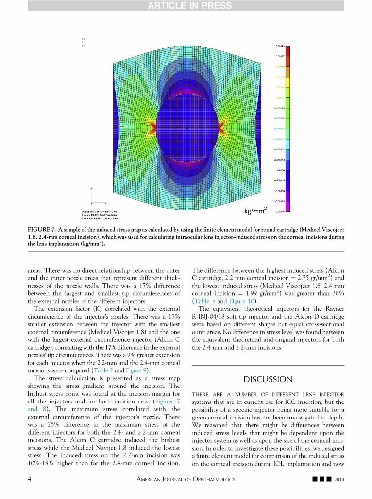
FIGURE 7. A sample of the induced stress map as calculated by using the finite element model for round cartridge (Medicel Viscoject1.8, 2.4-mm corneal incision), which was used for calculating intraocular lens injector–induced stress on the corneal incisions duringthe lens implantation (kg/mm2).
areas. There was no direct relationship between the outerand the inner nozzle areas that represent different thick-nesses of the nozzle walls. There was a 17% differencebetween the largest and smallest tip circumferences ofthe external nozzles of the different injectors.
The extension factor (K) correlated with the externalcircumference of the injector’s nozzles. There was a 17%smaller extension between the injector with the smallestexternal circumference (Medicel Viscojet 1.8) and the onewith the largest external circumference injector (Alcon Ccartridge), correlating with the 17%difference in the externalnozzles’ tip circumferences. There was a 9% greater extensionfor each injector when the 2.2-mm and the 2.4-mm cornealincisions were compared (Table 2 and Figure 9).
The stress calculation is presented as a stress mapshowing the stress gradient around the incision. Thehighest stress point was found at the incision margin forall the injectors and for both incision sizes (Figures 7and 8). The maximum stress correlated with theexternal circumference of the injector’s nozzle. Therewas a 25% difference in the maximum stress of thedifferent injectors for both the 2.4- and 2.2-mm cornealincisions. The Alcon C cartridge induced the higheststress while the Medicel Navijet 1.8 induced the loweststress. The induced stress on the 2.2-mm incision was10%-13% higher than for the 2.4-mm corneal incision.
4 AMERICAN JOURNAL OF
The difference between the highest induced stress (AlconC cartridge, 2.2 mm corneal incision ¼ 2.75 gr/mm2) andthe lowest induced stress (Medicel Viscoject 1.8, 2.4 mmcorneal incision ¼ 1.99 gr/mm2) was greater than 38%(Table 3 and Figure 10).The equivalent theoretical injectors for the Rayner
R-INJ-04/18 soft tip injector and the Alcon D cartridgewere based on different shapes but equal cross-sectionalouter areas. No difference in stress level was found betweenthe equivalent theoretical and original injectors for boththe 2.4-mm and 2.2-mm incisions.
DISCUSSION
THERE ARE A NUMBER OF DIFFERENT LENS INJECTOR
systems that are in current use for IOL insertion, but thepossibility of a specific injector being more suitable for agiven corneal incision has not been investigated in depth.We reasoned that there might be differences betweeninduced stress levels that might be dependent upon theinjector system as well as upon the size of the corneal inci-sion. In order to investigate these possibilities, we designeda finite element model for comparison of the induced stresson the corneal incision during IOL implantation and now
--- 2014OPHTHALMOLOGY
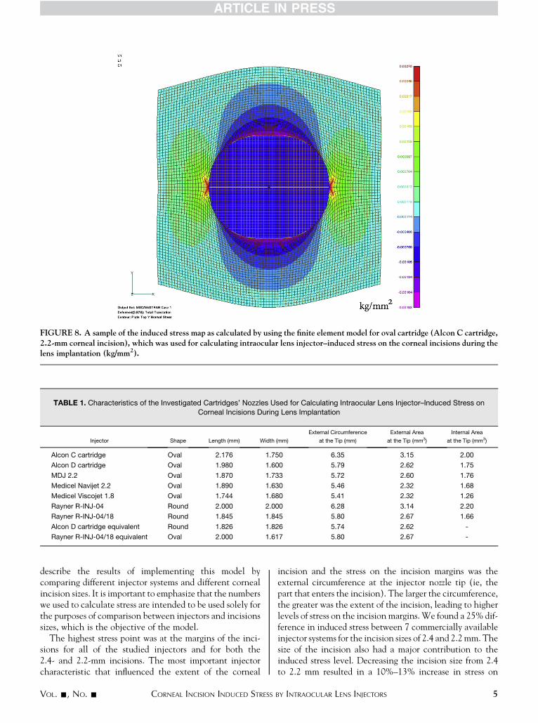
FIGURE 8. A sample of the induced stress map as calculated by using the finite element model for oval cartridge (Alcon C cartridge,2.2-mm corneal incision), which was used for calculating intraocular lens injector–induced stress on the corneal incisions during thelens implantation (kg/mm2).
TABLE 1. Characteristics of the Investigated Cartridges’ Nozzles Used for Calculating Intraocular Lens Injector–Induced Stress on
Corneal Incisions During Lens Implantation
Injector Shape Length (mm) Width (mm)
External Circumference
at the Tip (mm)
External Area
at the Tip (mm3)
Internal Area
at the Tip (mm3)
Alcon C cartridge Oval 2.176 1.750 6.35 3.15 2.00
Alcon D cartridge Oval 1.980 1.600 5.79 2.62 1.75
MDJ 2.2 Oval 1.870 1.733 5.72 2.60 1.76
Medicel Navijet 2.2 Oval 1.890 1.630 5.46 2.32 1.68
Medicel Viscojet 1.8 Oval 1.744 1.680 5.41 2.32 1.26
Rayner R-INJ-04 Round 2.000 2.000 6.28 3.14 2.20
Rayner R-INJ-04/18 Round 1.845 1.845 5.80 2.67 1.66
Alcon D cartridge equivalent Round 1.826 1.826 5.74 2.62 -
Rayner R-INJ-04/18 equivalent Oval 2.000 1.617 5.80 2.67 -
describe the results of implementing this model bycomparing different injector systems and different cornealincision sizes. It is important to emphasize that the numberswe used to calculate stress are intended to be used solely forthe purposes of comparison between injectors and incisionssizes, which is the objective of the model.
The highest stress point was at the margins of the inci-sions for all of the studied injectors and for both the2.4- and 2.2-mm incisions. The most important injectorcharacteristic that influenced the extent of the corneal
VOL. -, NO. - CORNEAL INCISION INDUCED STRESS
incision and the stress on the incision margins was theexternal circumference at the injector nozzle tip (ie, thepart that enters the incision). The larger the circumference,the greater was the extent of the incision, leading to higherlevels of stress on the incision margins.We found a 25% dif-ference in induced stress between 7 commercially availableinjector systems for the incision sizes of 2.4 and 2.2mm. Thesize of the incision also had a major contribution to theinduced stress level. Decreasing the incision size from 2.4to 2.2 mm resulted in a 10%–13% increase in stress on
5BY INTRAOCULAR LENS INJECTORS
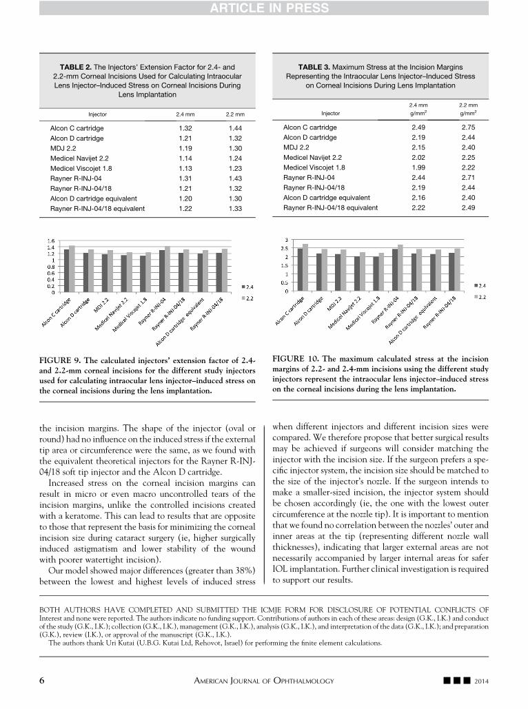
TABLE 2. The Injectors’ Extension Factor for 2.4- and2.2-mm Corneal Incisions Used for Calculating Intraocular
Lens Injector–Induced Stress on Corneal Incisions During
Lens Implantation
Injector 2.4 mm 2.2 mm
Alcon C cartridge 1.32 1.44
Alcon D cartridge 1.21 1.32
MDJ 2.2 1.19 1.30
Medicel Navijet 2.2 1.14 1.24
Medicel Viscojet 1.8 1.13 1.23
Rayner R-INJ-04 1.31 1.43
Rayner R-INJ-04/18 1.21 1.32
Alcon D cartridge equivalent 1.20 1.30
Rayner R-INJ-04/18 equivalent 1.22 1.33
FIGURE 9. The calculated injectors’ extension factor of 2.4-and 2.2-mm corneal incisions for the different study injectorsused for calculating intraocular lens injector–induced stress onthe corneal incisions during the lens implantation.
TABLE 3. Maximum Stress at the Incision MarginsRepresenting the Intraocular Lens Injector–Induced Stress
on Corneal Incisions During Lens Implantation
Injector
2.4 mm
g/mm2
2.2 mm
g/mm2
Alcon C cartridge 2.49 2.75
Alcon D cartridge 2.19 2.44
MDJ 2.2 2.15 2.40
Medicel Navijet 2.2 2.02 2.25
Medicel Viscojet 1.8 1.99 2.22
Rayner R-INJ-04 2.44 2.71
Rayner R-INJ-04/18 2.19 2.44
Alcon D cartridge equivalent 2.16 2.40
Rayner R-INJ-04/18 equivalent 2.22 2.49
FIGURE 10. The maximum calculated stress at the incisionmargins of 2.2- and 2.4-mm incisions using the different studyinjectors represent the intraocular lens injector–induced stresson the corneal incisions during the lens implantation.
the incision margins. The shape of the injector (oval orround) had no influence on the induced stress if the externaltip area or circumference were the same, as we found withthe equivalent theoretical injectors for the Rayner R-INJ-04/18 soft tip injector and the Alcon D cartridge.
Increased stress on the corneal incision margins canresult in micro or even macro uncontrolled tears of theincision margins, unlike the controlled incisions createdwith a keratome. This can lead to results that are oppositeto those that represent the basis for minimizing the cornealincision size during cataract surgery (ie, higher surgicallyinduced astigmatism and lower stability of the woundwith poorer watertight incision).
Our model showed major differences (greater than 38%)between the lowest and highest levels of induced stress
6 AMERICAN JOURNAL OF
when different injectors and different incision sizes werecompared. We therefore propose that better surgical resultsmay be achieved if surgeons will consider matching theinjector with the incision size. If the surgeon prefers a spe-cific injector system, the incision size should be matched tothe size of the injector’s nozzle. If the surgeon intends tomake a smaller-sized incision, the injector system shouldbe chosen accordingly (ie, the one with the lowest outercircumference at the nozzle tip). It is important to mentionthat we found no correlation between the nozzles’ outer andinner areas at the tip (representing different nozzle wallthicknesses), indicating that larger external areas are notnecessarily accompanied by larger internal areas for saferIOL implantation. Further clinical investigation is requiredto support our results.
BOTH AUTHORS HAVE COMPLETED AND SUBMITTED THE ICMJE FORM FOR DISCLOSURE OF POTENTIAL CONFLICTS OFInterest and none were reported. The authors indicate no funding support. Contributions of authors in each of these areas: design (G.K., I.K.) and conductof the study (G.K., I.K.); collection (G.K., I.K.), management (G.K., I.K.), analysis (G.K., I.K.), and interpretation of the data (G.K., I.K.); and preparation(G.K.), review (I.K.), or approval of the manuscript (G.K., I.K.).
The authors thank Uri Kutai (U.B.G. Kutai Ltd, Rehovot, Israel) for performing the finite element calculations.
--- 2014OPHTHALMOLOGY

REFERENCES
1. Milazzo S, Turut P, Blin H. Alterations to the AcrySof intra-ocular lens during folding. J Cataract Refract Surg 1996;22(Suppl 2):1351–1354.
2. VrabecMP, Syverud JC, Burgess CJ. Forceps-induced scratch-ing of a foldable acrylic intraocular lens (letter). ArchOphthalmol 1996;114(6):777.
3. Pfister DR. Stress fractures after folding an acrylic intraocularlens. Am J Ophthalmol 1996;121(5):572–574.
4. Carlson KH, Johnson DW. Cracking of acrylic intraocularlenses during capsular bag insertion. Ophthalmic Surg Lasers
1995;26(6):572–573.5. Kohnen T, Magdowski G, Koch DD. Scanning electron micro-
scopic analysis of foldable acrylic and hydrogel intraocularlenses. J Cataract Refract Surg 1996;22(Suppl 2):1342–1350.
6. Kleinmann G, Marcovich AL, Apple DJ, Mamalis N.Linear deposits on the surfaces of intraocular lenses
VOL. -, NO. - CORNEAL INCISION INDUCED STRESS
implanted through a hexagonal injector which mimicscratches/cracks on the lenses. Br J Ophthalmol 2005;89(11):1474–1477.
7. Marcovick AL, Kleinmann G, Epstein D, Pollack A. Thecourse of surface deposits on a hydrophilic acrylic intraocularlens after implantation through a hexagonal cartridge. Br JOphthalmol 2006;90(10):1249–1251.
8. Satanovsky A, Ben-Eliahu S, Apple DJ, Kleinmann G. Safetyassessment of a new single-use small-incision injector forintraocular lens implantation. J Cataract Refract Surg 2011;37(7):1323–1328.
9. Masket S, Belani S. Proper wound construction to preventshort-term ocular hypotony after clear corneal incisioncataract surgery. J Cataract Refract Surg 2007;33(3):383–386.
10. Hamilton KE, Pye DC. Young’s modulus in normal corneasand effect on applanation tonometry. Optom Vis Sci 2008;85(6):445–450.
7BY INTRAOCULAR LENS INJECTORS
Biosketch
Guy Kleinmann, MD is the Director of the Cataract Surgery Service at the Kaplan Medical Center, Rehovot, Israel and a
Senior Lecturer of Ophthalmology at The School of Medicine of the Hebrew University, Jerusalem. His fields of clinical
and research interest include cataract surgery complications, intraocular lenses complications, premium intraocular lenses,
intraocular lens injector systems, cornea surgeries and refractive surgeries.
7.e1 --- 2014AMERICAN JOURNAL OF OPHTHALMOLOGY