intevras company overview jan 09
TRANSCRIPT

1Company Overview – January 2009

2
Company Overview:• INTEVRAS Technologies LLC - developer of a patented suite of innovative
technologies for water purification, remediation and process improvement
INTEVRAS offers two patented technologies:• INTEGRA : Automated Disk Filtration System• EVRAS : Evaporative Reduction and Solidification System
• Commercial Stage - Intevras is now in commercial stage of the technology. Deliverables to date:
– Patents issued and additional pending– Manufacturing agreement in place with several units in production– Opportunity identified in compressor inter-cooling for natural gas
compression
• Experienced Management– Decades of experience in oil and gas, water treatment, independent
power, and food processing industries.
• Corporate – Texas LLC, headquartered in Austin, TX
3
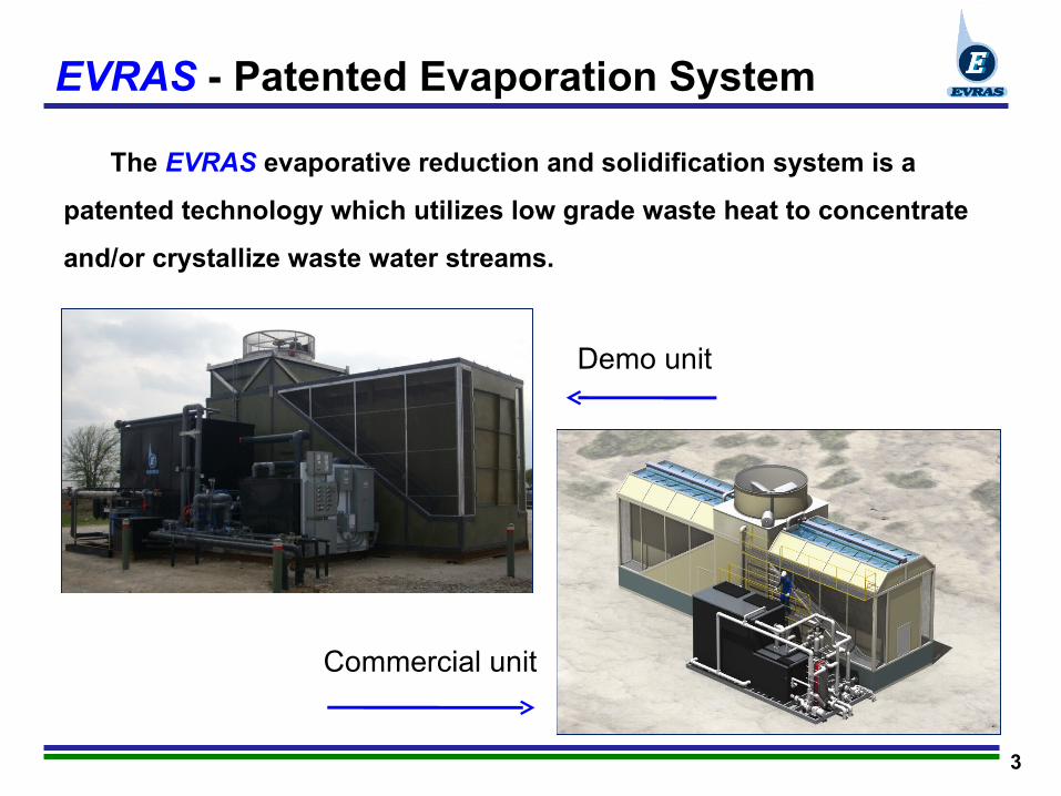
EVRAS - Patented Evaporation System
Demo unit
Commercial unit
The EVRAS evaporative reduction and solidification system is a
patented technology which utilizes low grade waste heat to concentrate
and/or crystallize waste water streams.

4
Solutions for Intevras Customers
The EVRAS system solves multiple problems at once:
• Increases gas flow while maintaining horsepower through the removal of inter-stage gas heat from compressors.
• Reduces compressor overheating through the removal of heat from engine jacket water.
• Decreases the number of trucks required at a site by reducing the overall volume of the waste stream.
• Provides increased “Green” revenues for producer and boosts the producers’ “Green Image”.

5
EVRAS: Cooling Benefits to Compressor OperationsCompressor benefits from lower cooling temperatures• Engine power reduction is not necessary• Gas Staged Compressor throughput is increased
EVRAS + Production Brine = Enhanced Compressor Cooling = Continuous Full Power + Higher Gas Throughput= Increased “Green” Revenues for the Producer
EVRAS Marcellus Shale: Mid Pennsylvania
Intercooling Delta Temp
0
5
10
15
20
25
Jan Feb March April May June July Aug Sept Oct Nov Dec
Month
Deg
F
13.2o13.1o
15.0o
16.2o
19.5o
17.4o 17.5o
16.8o 16.7o
15.3o
14.1o
12.7o
Thermal Source: 4 Cat 3606 @ 1675 net hpSource: Compression and Engine JW, AC3 Stage, 100x900 psi, 80F InletTotal Evap Air: 440kcfm, 4 Modules2007 Annual Metrology
10/20/08jjh
6
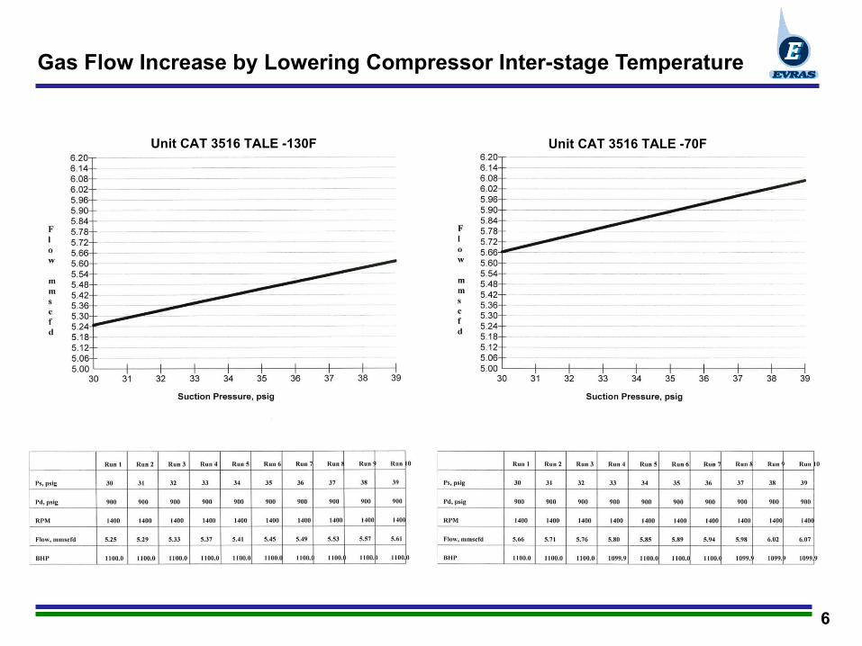
Gas Flow Increase by Lowering Compressor Inter-stage Temperature
Unit CAT 3516 TALE -130F Unit CAT 3516 TALE -70F
7
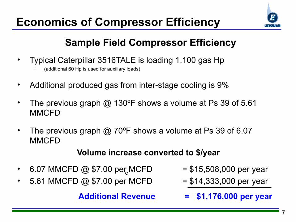
Economics of Compressor Efficiency
Sample Field Compressor Efficiency
• Typical Caterpillar 3516TALE is loading 1,100 gas Hp– (additional 60 Hp is used for auxiliary loads)
• Additional produced gas from inter-stage cooling is 9%
• The previous graph @ 130ºF shows a volume at Ps 39 of 5.61 MMCFD
• The previous graph @ 70ºF shows a volume at Ps 39 of 6.07 MMCFD
Volume increase converted to $/year
• 6.07 MMCFD @ $7.00 per MCFD = $15,508,000 per year
• 5.61 MMCFD @ $7.00 per MCFD = $14,333,000 per year
Additional Revenue = $1,176,000 per year
8
EVRAS Process Overview
• Uses natural evaporation- function of , water temperature, surface area,
ambient conditions and air flow.
• Utilizes low-grade waste heat to heat brine. (eg: from compressors)
• Eliminates scaling and fouling through a patented, direct-contact,
floating-bed (DCFB) heat transfer process.
• Enhances the evaporation process through deployment of a patented
undulating film/membrane technology.
• Has potential to provide improved compressor performance and/or
increased gas throughput.
9
EVRAS Value Proposition
•Insensitive to elevated TDS
•Enhances compressor performance by drawing waste heat from jacket water
and/or inter-stage cooling.
•Concentrates waste streams up to 90%, with full crystallization option if desired
•Eliminates scaling and fouling, minimizing downtime and maintenance expenses
•Process driven by waste heat
•Process occurs at low temperature and atmospheric pressure
•Guaranteed mechanical availability factor of 90% and above
•Instrumented for unmanned operation
•Modular Design
10
EVRAS - Oilfield Solutions
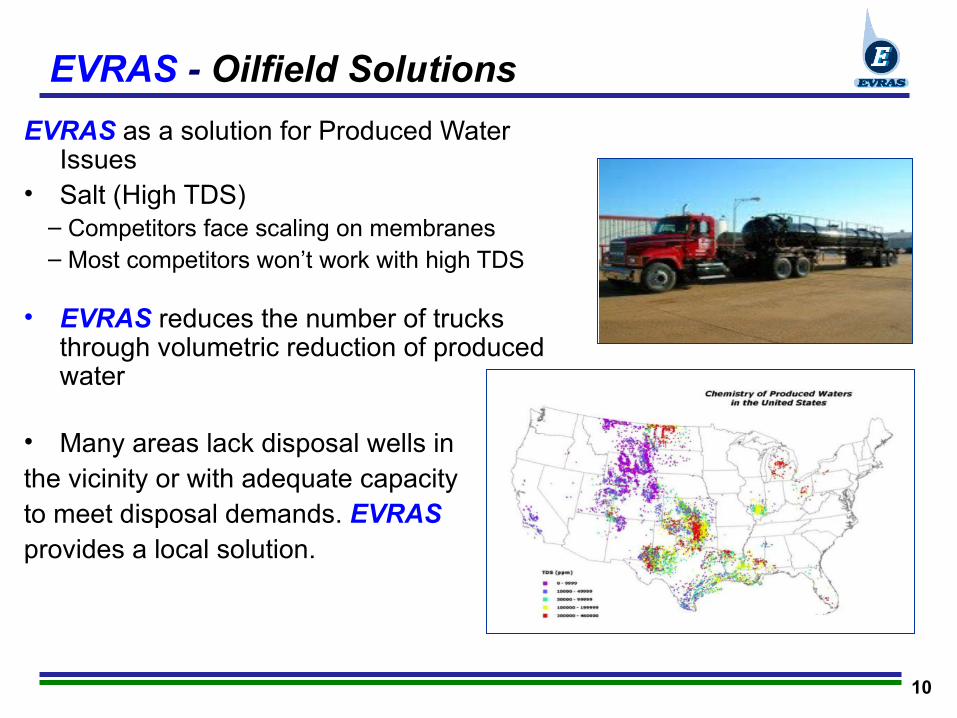
EVRAS as a solution for Produced Water Issues
• Salt (High TDS)– Competitors face scaling on membranes– Most competitors won’t work with high TDS
• EVRAS reduces the number of trucks through volumetric reduction of produced water
• Many areas lack disposal wells in the vicinity or with adequate capacityto meet disposal demands. EVRAS provides a local solution.
11
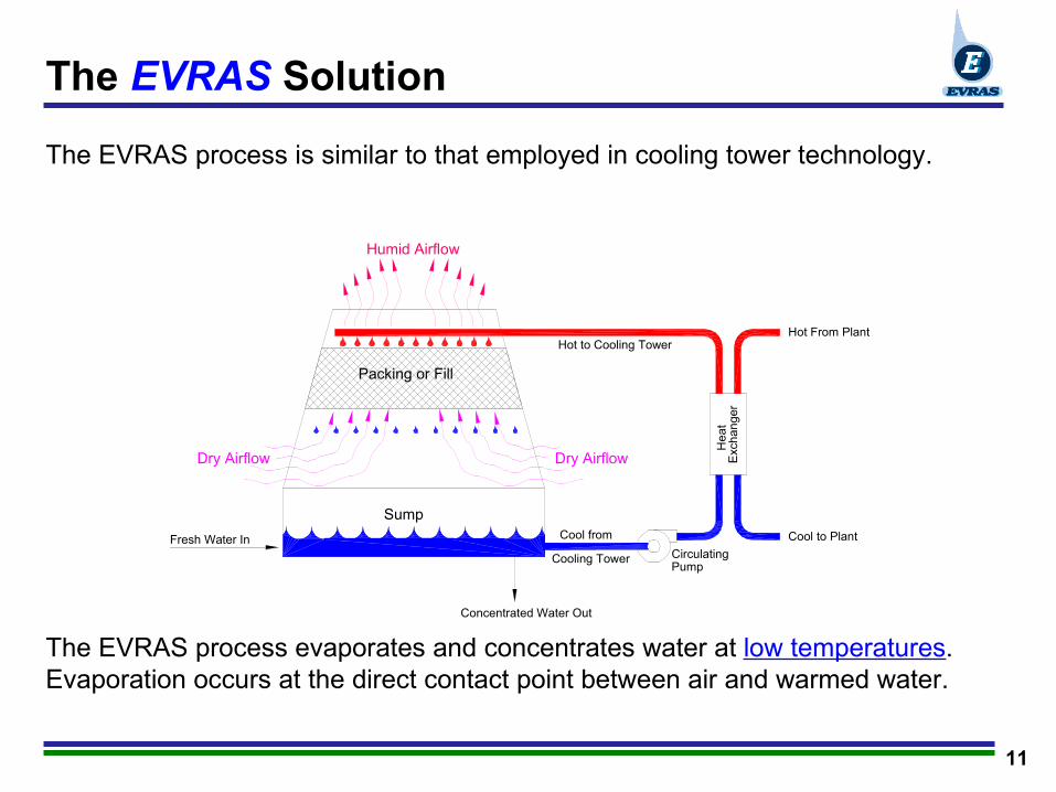
The EVRAS process is similar to that employed in cooling tower technology.
Dry Airflow Dry Airflow
Humid Airflow
He
at
Exc
ha
ng
er
Cool to Plant
Hot From PlantHot to Cooling Tower
Cool from
Cooling Tower Circulating Pump
Packing or Fill
Sump
Fresh Water In
Concentrated Water Out
The EVRAS process evaporates and concentrates water at low temperatures. Evaporation occurs at the direct contact point between air and warmed water.
The EVRAS Solution
12
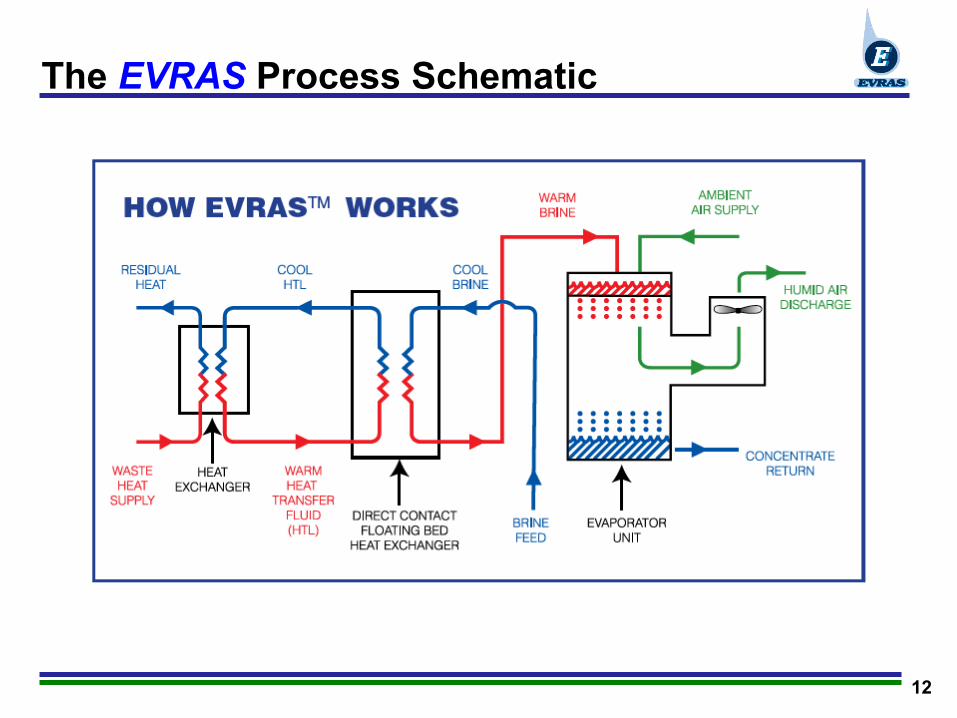
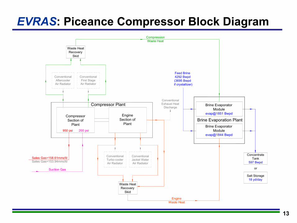
The EVRAS Process Schematic
13
ConventionalAftercoolerAir Radiator
ConventionalFirst StageAir Radiator
ConventionalTurbo-coolerAir Radiator
ConventionalJacket WaterAir Radiator
ConventionalExhaust Heat
Discharge
CompressorSection of
Plant
EngineSection of
Plant
Compressor Plant
Waste HeatRecovery
Skid
Waste HeatRecovery
Skid
Feed Brine4292 Bwpd(3695 Bwpd
if crystallizer)
Brine EvaporatorModule
evap@1851 Bwpd
Brine EvaporatorModule
evap@1844 Bwpd
Brine Evaporation Plant
ConcentrateTank
597 Bwpd
CompressionWaste Heat
EngineWaste Heat
Sales Gas=158.61mmcfdSales Gas=153.94mmcfd
Suction Gas
950 psi 200 psi
Salt Storage18 yd/day
or
EVRAS: Piceance Compressor Block Diagram
14
DCFB Heat Exchange Process
Features of the DCFB (Direct Contact Floating Bed) heat exchange
process include:
• Patented technology
•Employs proprietary heat transfer fluid that is immiscible with water and
has no solubility for scale-forming minerals
•Liquid-to-liquid heat exchange process employs no solid surfaces to
scale or foul
•Polymer spheres in DCFB tank maximize heat exchange by increasing
surface area.
15
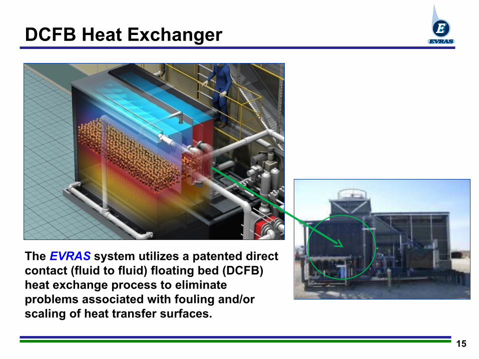
DCFB Heat Exchanger
The EVRAS system utilizes a patented direct contact (fluid to fluid) floating bed (DCFB) heat exchange process to eliminate problems associated with fouling and/or scaling of heat transfer surfaces.
16
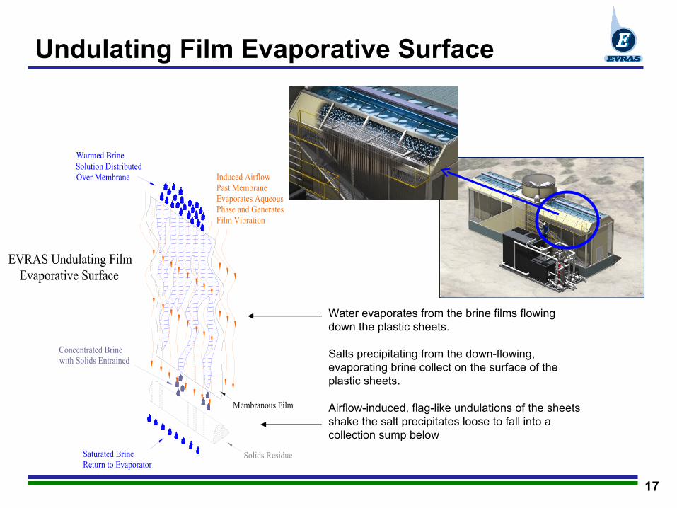
Undulating Film Evaporative Surface
Features of the Undulating Film Evaporative Surface include:
• Patented technology
•Maximizes surface area for contact between water and induced air flow
to optimize evaporation.
• Co-current, top-down air and water flow optimizes evaporation
• Evaporation surface equates to a one (1) acre evaporation pit, with
a footprint 53X smaller.
•Undulating motion generates vibration sufficient to dislodge salt crystals
that may form on the membrane surface.
17
Induced AirflowPast MembraneEvaporates AqueousPhase and GeneratesFilm Vibration
Solution DistributedOver Membrane
Membranous Film
Concentrated Brinewith Solids Entrained
Solids ResidueSaturated Brine Return to Evaporator
Warmed Brine
EVRAS Undulating FilmEvaporative Surface
Undulating Film Evaporative Surface
Water evaporates from the brine films flowing down the plastic sheets. Salts precipitating from the down-flowing, evaporating brine collect on the surface of the plastic sheets.
Airflow-induced, flag-like undulations of the sheets shake the salt precipitates loose to fall into a collection sump below

18
EVRAS- Potential Markets
The EVRAS evaporative reduction and solidification system was developed as an outgrowth of volumetric reduction in the following industries. The technology can be used in a multitude of other industries and applications
• Landfill Leachate
• De-icing Fluid Recycling
• Chemical Production
• Food Processing
• Power Generation
• Oil & Gas Industry

19
Automated Disk Filtration
20
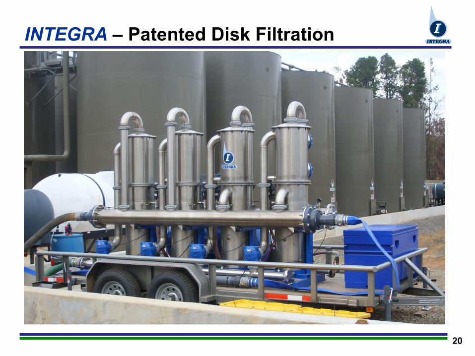
INTEGRA – Patented Disk Filtration
21
INTEGRA Technology Benefits
•Corrosion and chemical resistant
•Smallest equipment footprint in class
• Modular design allows staged filtration and expansion
capability
• 3 - 200 micron filtration ratings
•Low back-flush volume
•No pumps required for pneumatic back-flush
•Explosion proof
•Automatic self-cleaning operation
•Designed for the toughest industrial filtration needs

22
The INTEGRA Process SchematicFigure 7: In Filtration Mode
feed-waterDirty
External 2-wayflush valve (closed)
to ProcessFiltrate
Filter plenum
Filtrate plenum
Reaction plenum
Filtrate blockvalve (open)
Tension rod spring
Reaction plunger withfiltrate immersed seals
Air release outlet
Reaction air orifices
Sparger tubeopen ends
Filtrate fills the reactionplenum via weepage fromthe flush nozzles into thesparger tubes
disk stack via springDisk cap compresses the
tension on the tension rod
Dirty feed-water inlet
Filtrate outlet
Seal lubrication port
Figure 8: In Flushing Mode
flush valve (closed)External 2-way
Filter plenum
Filtrate plenum
Compressed air charge
upward by high pressureReaction plunger driven
High energy compressed air Reaction plenum
Dirty
inletfeed-water
Tension rod springadditionally compressed
drives filtrate downwardCompressed air charge
in reaction plenum andupward in the sparger tubes
entrains in the rising filtratevia the the reaction air orifices
with high energy air conveyedHigh pressure filtrate entrained
within the sparger tubes
within the reaction plenum
Collected solids
High pressure filtrate jets, entrained with compressedair, blast across the freefloating disks; scouringthem clean
flushed to discharge
Disk cap forcedupward by the spargertubes block the dirtyfeed-water inlet closed
tubes blocks the filtrate
Filtrate block forcedupward by the sparger
port closed
Waste flush outlet
Compressed air inlet
Seal lubrication port
FILTRATION MODE FLUSH MODE
23
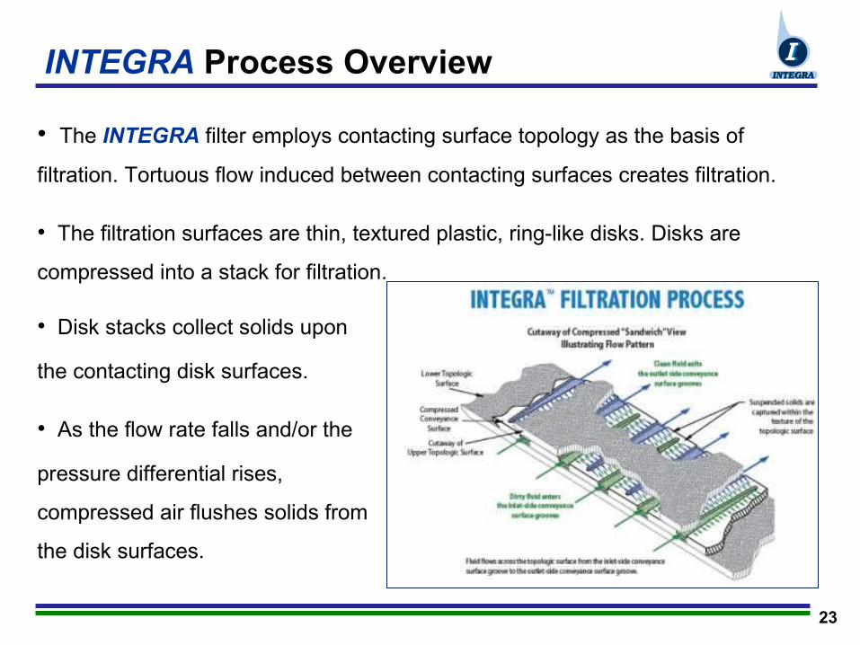
INTEGRA Process Overview
• The INTEGRA filter employs contacting surface topology as the basis of
filtration. Tortuous flow induced between contacting surfaces creates filtration.
• The filtration surfaces are thin, textured plastic, ring-like disks. Disks are
compressed into a stack for filtration.
• Disk stacks collect solids upon
the contacting disk surfaces.
• As the flow rate falls and/or the
pressure differential rises,
compressed air flushes solids from
the disk surfaces.
24
INTEGRA Value Proposition
Cost Effective Technology via:
•Durable disk materials (tolerant of hydrocarbons & most acids)
•Improved reliability and lower cost of operations through decreased
maintenance requirements.
•Reduced back-flush volume and chemical usage reduces disposal
needs.
•Modular design maximizes process flexibility.
•Automated control system requires minimal manning requirements.
•Warranted to be free of design and manufacturing defects.
25