international building code – fire safety fs2-09/10 · international building code – fire...
TRANSCRIPT

2010 ICC FINAL ACTION AGENDA 615
INTERNATIONAL BUILDING CODE – FIRE SAFETY
FS2-09/10 701.2 (New)
Proposed Change as Submitted
Proponent: Stephen Thomas, Colorado Code Consulting, LLC, representing the Colorado Chapter Add new text as follows: 701.2 Multiple use fire assemblies. Fire assemblies that serve multiple purposes in a building shall comply with all of the requirements that are applicable for each of the individual fire assemblies. Reason: A single fire assembly can serve multiple purposes in a structure. For example, a fire barrier along a fire-resistant rated corridor would also serve as a fire partition. The current code does not provide any direction on what requirements apply to that assembly. The intent of this proposal is to clarify that the requirements for each of the different assemblies must be met. In the example above, an opening protective would need to comply with the not only the fire-resistance rating for a fire barrier, but also the smoke and draft control requirements for an opening in a fire partition. Cost Impact: The code change proposal will not increase the cost of construction.
Public Hearing Results
Committee Action: Approved as Submitted Committee Reason: This proposal clarifies the current intent of the code by requiring compliance with all applicable code requirements for fire assemblies that serve multiple purposes. Assembly Action: None
Individual Consideration Agenda
This item is on the agenda for individual consideration because a public comment was submitted. Public Comment: Stephen Thomas representing Colorado Chapter ICC, requests Approval as Modified by this Public Comment. Modify the proposal as follows: 701.2 Multiple use fire and/or smoke assemblies. Fire and/or smoke assemblies that serve multiple purposes in a building shall comply with all of the requirements that are applicable for each of the individual fire assemblies. Commenter=s Reason: During the testimony in Baltimore, the committee identified a shortfall in the proposed language. It did not address smoke assemblies. Therefore, language has been added to confirm that this section would apply to fire and/or smoke assemblies. For example, a smoke barrier in a hospital that also serves as a fire barrier would need to comply with the requirements of both types of assemblies. This public comment does not change the overall intent or purpose of the proposed change. Final Action: AS AM AMPC D

2010 ICC FINAL ACTION AGENDA 616
FS3–09/10 702.1
Proposed Change as Submitted Proponent: Tony Crimi, A.C. Consulting Solutions Inc., representing International Firestop Council Revise as follows: JOINT. The linear opening void created at the interface in or between adjacent fire-resistance-rated assemblies building elements that is created due to building tolerances, or is designed to allow independent movement of the building in any plane caused by thermal, seismic, wind or any other loading. Reason: The purpose of this proposal is to clarify that a “Joint”, as defined in the IBC, may or may not be linear, and that the Joint is not the “opening” between fire resistance rated assemblies, but rather the materials or methods used to treat these openings Justification: “Joints” are interfaces created in or between building elements such as walls, floors, columns or other building items. A joint typically involves a continuous void at the interface of two or more distinct components. When joints are designed into a structure, they are intended to allow independent movement of the building in any plane caused by thermal, seismic, wind or any other loading. However, joints are sometimes created as a result of building construction tolerances. In fact, a Joint is never an “opening” as the current definition suggests, but instead they are the closures that go into the opening to provide continuity. The existing language in the definition already clarifies that the definition applies to both locations that are “… designed to allow independent movement” and also those created due to construction tolerances, and need to be treated. Consequently, the additional language addresses’ that portion of the scope of the definition. . Cost Impact: The code change proposal will not increase the cost of construction.
ICCFILENAME: CRIMI-FS6-702.1
Public Hearing Results
Committee Action: Disapproved Committee Reason: Using the term “building elements” limits the scope of the definition, based on the definition of building elements. Further, the term “linear opening” is specific and descriptive and should remain in the definition. Also, the term “linear” is consistent with terminology used in the referenced standards dealing with joints. Lastly, the term “void” is too broad. Assembly Action: None
Individual Consideration Agenda This item is on the agenda for individual consideration because a public comment was submitted. Public Comment: Tony Crimi, A.C. Consulting Solutions Inc., representing International Firestop Council, requests Approval as Modified by this Public Comment. Modify the proposal as follows: JOINT. The opening void created at the interface in or between adjacent fire-resistance-rated assemblies building elements that is created due to building tolerances, or is designed to allow independent movement of the building in any plane caused by thermal, seismic, wind or any other loading. Commenter’s Reason: This code change proposal clarifies that joints between fire resistance rated assemblies exist not only for the purposes of relative movement, but due to other reasons as well. The joint protection methods apply equally to all such gaps, regardless of why they exist. The term “Joint”, as utilized in Chapter 7, relates to the protective systems installed in gaps, joints, voids, or other discontinuities between (or bounded by) two or more supporting elements even when the opening is created due to building tolerances. Joints are present in buildings by design, to accommodate various movements induced by thermal differentials, seismicity, and wind loads, but they also exist as a clearance separation, or due to acceptable dimensional tolerances between two or more building elements, for example, between non-loadbearing walls and floors. Inadequate design, inaccurate assembly, repairs or damage to the building can also create a need to install joint systems. All of these are still required to be protected when they are located in or between fire-resistance rated assemblies
The proposed language presented here is consistent with the test standards used to test fire-resistant joint systems. Final Action: AS AM AMPC D

2010 ICC FINAL ACTION AGENDA 617
FS4-09/10 703.4
Proposed Change as Submitted Proponent: Tony Crimi, AC Consulting Solutions Inc., representing International Firestop Council Add new text as follows: 703.4 Automatic sprinklers. The fire resistance rating of a building element, component or assembly shall be established without the use of automatic sprinklers or any other fire suppression system being incorporated as part of the assembly tested in accordance with the fire exposure, procedures, and acceptance criteria specified in ASTM E119 or UL 263. (Renumber subsequent sections) Reason: There is a potential for misuse of established fire-resistance test Standards relied upon in the Code to determine performance of elements and assemblies, wherein the established consensus test method are modified outside the scope of the test standard to include a flow of cooling water during the fire exposure portion of the test.
Since some material manufacturers have begun to submit test reports to Authorities Having Jurisdiction with fire-resistance ratings obtained using a flow of cooling water during the fire test, it now becomes important to clarify that the code-required fire resistance rating is in fact a property that is meant to represent the inherent resistance to fire without the assistance of cooling flows. In countless instances, the code already incorporates the risk-reducing effect of a cooling flow from an extinguishing system by reducing the fire-resistance requirements, or by reducing other required safety measures.
The possibility of reducing some code requirements based on the improved behavior of an assembly when subjected to a cooling water flow can already be done via Alternative protection methods as allowed by Section 104.11, or by evaluation as a performance-based option. Thus, the only impact of this code change is to prevent a manufacturer of products from claiming an inflated fire resistance rating. The code change would not restrict anyone from proving that the addition of a cooling and/or extinguishing water flow can reduce some other requirement in the code.
It has never been the intent of either the Codes or the fire resistance testing Standards to incorporate the fire suppression system as part of the fire resistance rating of a building element, component or assembly. It would not be acceptable to have a fire-resistance rating that is determined during a test using a cooling flow, since the need for a fire resistive assembly is usually required by the Code in order to provide a an inherent passive level of fire protection. The notion of multiple safeguards and “Balanced Fire Protection” is not new to the Codes. It has long been a basic tenet that the design of every building or structure intended for human occupancy shall be such that reliance for safety to life does not depend solely on any single safeguard. Additional safeguards are provided for life safety in case any single safeguard is ineffective due to inappropriate human actions or system failure.
The resulting cooling-enhanced fire resistance rating then provides a result that would be incompatible with the required fire resistance ratings specified throughout the I-Codes. The various fire resistance ratings mandated throughout dozens of articles in the Code have been established based on an assumption of the type of construction that would pass the standardized tests without the aid of water cooling during fire exposure. For example, a relatively thin and un-insulated metal panel wall with suitable water cooling could potentially be arranged to pass a 1-hour standardized fire-resistance test, and possibly even longer duration fire-resistance tests. However, where the Code specifies the need for a 1-hour assembly, the intent in the development of that code provision would have clearly been to have an assembly that could survive a fire without being breached and without losing any load-bearing capabilities all by itself, without relying on an external water source for continued cooling. If sprinkler protection was also required for such an occupancy, then the overall intent of the Code is to have these two systems act independently, but in concert with each other. Cost Impact: The code change proposal will not increase the cost of construction. Analysis: Standards ASTM E119 and UL 263 are currently referenced in the I-codes. Public Hearing: Committee: AS AM D Assembly: ASF AMF DF
ICCFILENAME: CRIMI-FS3-703.4
Public Hearing Results Committee Action: Approved as Submitted Committee Reason: The committee agreed that passive and active fire protection should not be used together, specific to ASTM E119 and UL263 testing. Further, code officials should not be attempting to determine if a proposed test completely meets the requirements of test methods ASTM E119 or UL263. Lastly, adhoc tests that combine active and passive systems are not prohibited and can be reviewed and approved by the code official as alternative methods under Section 104.11 of the code. Assembly Action: None

2010 ICC FINAL ACTION AGENDA 618
Individual Consideration Agenda These items are on the agenda for individual consideration because public comments were submitted. Public Comment 1: Jeffrey M. Shapiro, P. E., International Code Consultants, representing TYCO Fire Suppression and Building Products, requests Approval as Modified by this Public Comment. Modify the proposal as follows: 703.4 Automatic sprinklers. Under the prescriptive fire resistance requirements of the International Building Code, Tthe fire resistance rating of a building element, component or assembly shall be established without the use of automatic sprinklers or any other fire suppression system being incorporated as part of the assembly tested in accordance with the fire exposure, procedures, and acceptance criteria specified in ASTM E119 or UL 263. However, this section shall not prohibit or limit the duties and powers of the building official allowed by Sections 104.10 and 104.11. Commenter=s Reason: The additional text is a necessary clarification of the new section, and it is consistent with the committee’s stated intent to not limit use of Section 104 for approving alternative methods on a case by case basis. The proponent of this code proposal also stated at the hearing that the addition of this section was clarification of the existing prescriptive code requirements for established fire-resistance test standards, and was not intended to usurp the ultimate authority of the code official’s powers under Section 104, “Duties and Powers of Building Official”.
Nevertheless, as the section is currently written, use of Section 104 would not be permissible since it would directly violate the requirements in Section 704.3. If the code says “you can’t use sprinklers as part of the test criteria…period,” then one can’t simply go to Section 104 and count sprinklers. It is understood that having the code simply accept the use of fire sprinklers as a consideration in any fire resistance test is inappropriate, except on a case-by-case basis when approved by the Code Official, and for that reason, we are not opposing the intent of the proposal, just the text. With the recommended modifications, code application will be clarified in a manner that seems to satisfy all interests that were expressed in Baltimore. Public Comment 2: Gene Boecker, Code Consultants, representing The National Association of Theatre Owners, requests Disapproval. Commenter=s Reason: Although not mentioned by name in the reason statement, the obvious subject of this proposal is ICC ESR-2397. No official is forced to accept ESR-2397, because it does not constitute a listed assembly. It is a tested assembly that can be submitted to the code official for approval as an alternative method in accordance with Section 104.11. Section 104.11 specifically requires the submittal of research reports to assist the official in making a decision on the approval of a material or assembly. The decision for many years was, appropriately, the code official’s. Now the ability to selectively apply this alternative, at the official’s discretion, will be taken away, despite the proponent’s argument to the contrary. Note that the proposal included no actual data regarding failures of this type of system. Also, note that the code itself allows sprinklered glazing in a number of applications (atrium enclosures, pedestrian walkway separations) as a direct equivalent method for fire resistive rated assemblies. These allowances have been in the codes for years and have not proven to be present an undue hazard. This change, if allowed to move forward, will place a prohibition on a system that has been used successfully in jurisdictions across the country for many years. It will also create confusion for systems where sprinklers are specifically addressed, as noted above. Based on the language of ESR-2397and Section 104.11, in every case where this system has been used it was ultimately the official’s decision that this system constituted an equivalent method for the protection of whatever building separation element the ESR-2397 compliant system was being proposed to protect. Appropriate limitations on its use are therefore based on the reasonable consideration of the building official, regardless of the proposed use. Unfortunately, what this code change will do is take this decision away from the building official, and add language to the code that will inhibit any future development of this type of technology. Final Action: AS AM AMPC D
FS5–09/10 703.4.1
Proposed Change as Submitted Proponent: Richard Porter and Robert Sullivan, cfiFOAM, Inc., representing themselves Revise as follows: 703.4.1 Elementary materials. Materials required to be noncombustible shall be tested in accordance with ASTM E 136.
Exception: Where foam plastic insulation is encased within either the core cells of concrete masonry wall assemblies or within the core spaces of precast hollow core concrete panel wall assemblies, the potential heat of

2010 ICC FINAL ACTION AGENDA 619
the foam plastic insulation shall be determined in accordance with NFPA 259 and the results shall be expressed in Btu per square feet (MJ/m2).
Reason: Section 2603 FOAM PLASTIC INSULATION makes no reference to ASTM E 136 but instead points to the significance of testing in accordance with NFPA 259 to measure the potential heat contribution of the foam plastic insulation incorporated into a wall or panel.
On one hand, NFPA 259 data shows that foam plastic insulation contributes very little fuel per square foot (MJ/W) of wall or panel area by virtue of its very low density; therefore, the presence of foam plastic insulation has little or no impact upon the fire resistance performance of a wall or panel assembly.
In measuring fuel contribution per wall or panel area, NFPA 259 data provides superior information vs. ASTM E 136 which provides only pass/fail criteria having to do with temperature rise and the fragility of foam plastic insulation.
On the other hand, foam plastic insulation offers resistance to heat flow as does any insulating material. By virtue of its encased presence within concrete masonry wall and precast concrete panel assemblies, the initial heat-up of assemblies exposed to fire is slightly retarded up to or until the point where the foam plastic insulation thermally degrades. This slight heat flow delay contributes slightly to the fire-rating of the wall assembly.
The positive contribution on the one hand is off-set by the negative contribution on the other hand. Cost Impact: The code change proposal will not increase the cost of construction. Analysis: Standard NFPA 259 is currently referenced in the I-codes.
ICCFILENAME: PORTER-SULLIVAN-FS1-703.4.1
Public Hearing Results
Committee Action: Disapproved Committee Reason: The committee agreed that Chapter 26 sufficiently deals with the requirements for foam plastic materials. Further, neither the proposed text nor the proposed test standard (NFPA 259) contains pass fail criteria. Therefore there is no guidance on what to do with the test results. Lastly, these requirements are in the wrong location as foam plastic materials are combustible materials. Assembly Action: None
Individual Consideration Agenda
This item is on the agenda for individual consideration because a public comment was submitted. Public Comment: Michael J. Wolfe, CE, M.J. Wolfe & Associates, requests Approval as Modified by this Public Comment. Modify the proposal as follows: 703.4.1 Elementary materials. Materials required to be noncombustible shall be tested in accordance with ASTM E 136.
Exception: Where foam plastic insulation is encased within a wall assembly by noncombustible materials such as concrete and steel either the core cells of concrete masonry wall assemblies or within the core spaces of precast hollow core concrete panel wall assemblies, the potential heat of the wall assembly foam plastic insulation shall be determined in accordance with NFPA 259 and the results shall be expressed in Btu per pound (kJ/kg). square feet (MJ/m2)
Commenter’s Reason: This commenter agrees that the NFPA 259 test protocol should be used to determine the Potential Heat released by a building material and included under section 703.4 as an additional means of qualifying a building material as either a non-combustible, limited-combustible or combustible material. The NFPA 259 test expresses the Potential Heat of a particular material in btu/lb. and is a superior test method for proving combustibility and fire performance characteristics than the ASTM E-136 test, which provides only pass/fail criteria.
However, the commenter recommends that the test results be expressed in btu/lb, as per the NFPA 259 Standard Test Method for Potential Heat of Building Materials, which can then be converted to btu/sq. ft. by mathematical calculation. Final Action: AS AM AMPC D

2010 ICC FINAL ACTION AGENDA 620
FS7-09/10 703.6
Proposed Change as Submitted Proponent: Valarie Loper, City of North Las Vegas Building Safety Revise as follows: 703.6 Marking and identification. Fire walls, fire barriers, fire partitions, smoke barriers, and smoke partitions or any other wall required to have protected openings or penetrations shall be effectively and permanently identified with signs or stenciling. Such identification shall:
1. Be located in accessible concealed floor floor-ceiling or attic spaces; 2. Be repeated located with in 15 feet (4572 mm ) of the end of each wall and at intervals not exceeding 30 feet
(9144mm) measured horizontally along the wall or partition; and 3. Included lettering not less than 3 inches (76 mm ) 0.5 inch (12.7mm) in height in a contrasting color
incorporating the suggested wording. “FIRE AND/OR SMOKE BARRIER—PROTECT ALL OPENINGS” or other wording.
Exception: Walls in Group R-2 occupancies that do not have a removable decorative ceiling allowing access to the concealed space.
Reason: I believe this is a needed code to assist in maintaining the integrity of fire resistive construction. The change to a larger size of3 Inches will better ensure that the lettering will be seen by the contractors and subcontractors that will be creating unprotected openings in protected assemblies. The contrasting color will regulate that the lettering be installed in a color that will contrast the base color of the assembly also ensuring a better chance of this identification being achieved. To install this lettering within 15 feet of the end of each wall will also aid in the ability of the persons remodeling the existing wall to be informed of the need to protect any openings made. The maintaining of a fire resistive assembly is as important as the creating of the assembly was to begin with. Cost Impact: The code change proposal will increase the cost of construction.
ICCFILENAME: LOPER-FS1-703.6.doc
Public Hearing Results Committee Action: Approved as Modified Modify the proposal as follows: 703.6 Marking and identification. Fire walls, fire barriers, fire partitions, smoke barriers, and smoke partitions or any other wall required to have protected openings or penetrations shall be effectively and permanently identified with signs or stenciling. Such identification shall:
1. Be located in accessible concealed floor floor-ceiling or attic spaces; 2. Be located with in 15 feet (4572 mm ) of the end of each wall and at intervals not exceeding 30 feet (9144mm) measured horizontally
along the wall or partition; and 3. Included lettering not less than 3 inches (76 mm ) in height with a minimum 3/8 inch (9.5 mm) stroke in a contrasting color incorporating
the suggested wording. “FIRE AND/OR SMOKE BARRIER—PROTECT ALL OPENINGS” or other wording.
Exception: Walls in Group R-2 occupancies that do not have a removable decorative ceiling allowing access to the concealed space. Committee Reason: The committee agreed that the closer spacing and larger letter height would aid in enforcement of these provisions. The modification provides for consistent letter sizing, which again will aid in enforcement of these provisions. Assembly Action: None

2010 ICC FINAL ACTION AGENDA 621
Individual Consideration Agenda This item is on the agenda for individual consideration because a public comment was submitted. Public Comment: Lawrence G. Perry, AIA, representing Building Owners and Managers Association (BOMA) International requests Approval as Modified. Further modify the proposal as follows: 703.6 Marking and identification. Fire walls, fire barriers, fire partitions, smoke barriers, and smoke partitions or any other wall required to have protected openings or penetrations shall be effectively and permanently identified with signs or stenciling. Such identification shall:
1. Be located in accessible concealed floor floor-ceiling or attic spaces; 2. Be located within 15 feet (4572 mm ) of the end of each wall and at intervals not exceeding 30 feet (9144mm) measured horizontally along the wall or partition; and 3. Include lettering not less than 1 inch (25 mm) 3 inches (76 mm ) in height with a minimum 3/8” (9.5 mm) stroke in a contrasting color incorporating the suggested wording. “FIRE AND/OR SMOKE BARRIER—PROTECT ALL OPENINGS” or other wording.
Exception: Walls in Group R-2 occupancies that do not have a removable decorative ceiling allowing access to the concealed space. Commenter=s Reason: The current code provision, new to the 2009 edition, requires 1/2" high characters. This code change increased the minimum height to 3”. While this might make sense on a wall where the marking would be observed from a distance away (such as high on an exposed wall, or on a large exposed wall in an equipment room), the provision does not require the markings in locations likely to be viewed from any significant distance. The markings are required only in concealed spaces, where someone is likely to be poking their head up through an opening into a small space. The proposed modification for minimum 1” characters is more than adequate for the short viewing distance that will occur for these markings. With shorter character height, the stroke width issue is less critical, and becomes an unnecessary complication for what is supposed to be a simple marking. Final Action: AS AM AMPC D
FS9-09/10 704.2, 704.3, 704.4
Proposed Change as Submitted
Proponent: Sam Francis representing American Forest & Paper Association Revise as follows: 704.2 Column protection. Where columns are required to be fire-resistance rated, the entire column shall be provided individual encasement protection by protecting it on all sides for the full column length, including connections to other structural members, with materials having the required fire-resistance rating. Where the column extends through a ceiling, the encasement protection shall be continuous from the top of the foundation or floor/ceiling assembly below through the ceiling space to the top of the column. Exception: Columns complying with Section 602.4, 721.1 or 721.6.3 704.3 Protection of the primary structural frame other than columns. Members of the primary structural frame other than columns that are required to have a fire-resistance rating and support more than two floors or one floor and roof, or support a load-bearing wall or a nonload-bearing wall more than two stories high, shall be provided individual encasement protection by protecting them on all sides for the full length, including connections to other structural members, with materials having the required fire-resistance rating. Exceptions:
1. Individual encasement protection on all sides shall be permitted on all exposed sides provided the extent of protection is in accordance with the required fire-resistance rating, as determined in Section 703.
2. Members complying with Section 602.4, 721.1 or 721.6.3 704.4 Protection of secondary members. Secondary members that are required to have a fire-resistance rating

2010 ICC FINAL ACTION AGENDA 622
shall be protected by individual encasement protection, by the membrane or ceiling of a horizontal assembly in accordance with 712, or by a combination of both 704.4.1 Light-frame protection. King studs and boundary elements that are integral elements in load- bearing walls of light-framed construction shall be permitted to have required fire-resistance ratings provided by the membrane protection provided for the load-bearing wall. 704.4.2 Alternative protection. Structural elements complying with Section 602.4, 721.1 or 721.6.3 shall not be required to comply with Section 704.4. Reason: Wood members of sufficiently large section to be considered heavy timber have never been required to be protected with a membrane in order to be considered heavy timber. There has been some confusion about the fire resistive properties of heavy timber as compared to the fire resistance of large members determined by the calculation methodology in Section 721. This confusion has led to a misapplication of Section 714 and its provision for protecting the member on all sides by materials having the required fire resistance. In the case of large wood members used in Type IV Construction as defined in Section 602.4, there is an inherent protection afforded the member by the char layer that forms as the timber is pyrolized. Table 601 recognizes this unique characteristic and distinguishes it from a fire resistance by utilizing the term “heavy timber” to describe this type of construction. Moreover, the calculation methodology in Section 721 also relies on the insulating qualities of the char layer in order to calculate the size of member which will afford a sufficient sacrificial layer and still have adequate section to resist 100% of the required loads imposed on it. Accordingly, neither members complying with Section 602 nor members complying with Section 721 require further protection as required in Section 704. This code change is intended to make it clear that large wood members conforming to 602 or to 721 are not required to have this additional and redundant layer of protection. Cost Impact: The code change proposal will not increase the cost of construction.
ICCFILENAME: FRANCIS-FS2-704.2
Public Hearing Results Committee Action: Disapproved Committee Reason: The committee felt that these provisions were confusing and should be located in charging text rather than in an exception. Further, it would be more appropriate for the provisions to be located where the code addresses heavy timber construction. Assembly Action: None
Individual Consideration Agenda
These items are on the agenda for individual consideration because public comments were submitted. Public Comment 1: Sam Francis, representing the American Wood Council/AF&PA, requests Approval as Modified by this Public Comment. Replace the proposal as follows: 602.4.1 Columns. Wood columns shall be sawn or glued laminated and shall not be less than 8 inches nominal, in any dimension where supporting floor loads and not less than 6 inches nominal in width and not less than 8 inches nominal in depth where supporting roof and ceiling loads only. Columns shall be continuous or superimposed and connected in an approved manner. Protection in accordance with Section 704.2 is not required. Commenter=s Reason: It is widely understood that heavy timber does not require the encapsulation required of columns in Section 704 in order to achieve its inherent fire performance. The committee believed that the notation that such protection was not required would be better placed in the Heavy Timber section. This comment proposes to place the language in the location and in the manner suggested by the Fire Safety Code Development Committee. Public Comment 2: Jonathan Humble, AIA, representing the American Iron & Steel Institute, requests Approval as Modified by this Public Comment. Modify the proposal as follows: 704.2 Column protection. Where columns are required to have protection to be fire-resistance rated, the entire column shall be provided individual encasement protection by protecting it on all sides for the full column length, including connections to other structural members, with materials having the required fire-resistance rating. Where the column extends through a ceiling, the encasement protection shall be continuous from the top

2010 ICC FINAL ACTION AGENDA 623
of the foundation or floor/ceiling assembly below through the ceiling space to the top of the column. Exception: Columns complying with Section 602.4, 721.1 or 721.6.3 704.3 Protection of the primary structural frame other than columns. Members of the primary structural frame other than columns that are required to have protection to achieve a fire-resistance rating and support more than two floors or one floor and roof, or support a load-bearing wall or a nonload-bearing wall more than two stories high, shall be provided individual encasement protection by protecting them on all sides for the full length, including connections to other structural members, with materials having the required fire-resistance rating. Exceptions:
1. Individual encasement protection on all sides shall be permitted on all exposed sides provided the extent of protection is in accordance with the required fire-resistance rating, as determined in Section 703.
2. Members complying with Section 602.4, 721.1 or 721.6.3 704.4 Protection of secondary members. Secondary members that are required to have a fire-resistance rating shall be protected by individual encasement protection, by the membrane or ceiling of a horizontal assembly in accordance with 712, or by a combination of both 704.4.1 Light-frame protection. King studs and boundary elements that are integral elements in load- bearing walls of light-framed construction shall be permitted to have required fire-resistance ratings provided by the membrane protection provided for the load-bearing wall. 704.4.2 Alternative protection. Structural elements complying with Section 602.4, 721.1 or 721.6.3 shall not be required to comply with Section 704.4. Commenter=s Reason: This public comment addresses the concerns of the Code Committee in terms of eliminating the confusing language, and placing the provisions in the charging text rather than in an exception.
The pubic comment also generalizes the original proposal FS9-09/10 to cover not only heavy timber structural members, but all structural members that do not need protection in order to achieve a fire-resistance rating. This would correct an existing conflict within the code language that requires encasement, membrane or ceiling protection regardless of whether the fire resistance rated design required any protection or not.
Approval of this modification would address many types of tested and fire-resistance rated constructions that achieve fire resistance ratings without protection, such as:
Unprotected heavy timber members, rated in accordance with IBC section 721, Unprotected reinforced concrete members, rated in accordance with IBC section 721, Steel columns complying with IBC Table 720.1(1) item 1-9.1, Unprotected concrete-filled tubular steel columns complying with ASCE-29, Section 5.2.3, Unprotected concrete over steel deck floors, tested and rated in accordance with ASTM E119, and listed by testing agencies.
Final Action: AS AM AMPC D FS11–09/10 705.2, TABLE 705.2 (New)
Proposed Change as Submitted Proponent: Gary Lampella, City of Redmond, OR, representing Oregon Building Officials Association 1. Revise as follows:
SECTION 705 EXTERIOR WALLS
705.2. Projections. Cornices, eave overhangs, exterior balconies and similar projections extending beyond the exterior wall shall conform to the requirements of this section and Section 1406. Exterior egress balconies and exterior exit stairways shall also comply with Sections 1019 and 1026, respectively. Projections shall not extend beyond the distance determined by the following three two methods, whichever results in the lesser projection:
1. A point one-third the distance from the exterior face of the wall to the lot line where protected openings or a combination of protected and unprotected openings are required in the exterior wall from an assumed vertical plane in accordance with Table 705.2.
2. A point one-half the distance from the exterior face of the wall to the lot line where all openings in the exterior wall are permitted to be unprotected or the building is equipped throughout with an automatic sprinkler system installed under the provisions of Section 705.8.2.
2 3. More than 12 inches (305 mm) into areas where openings are prohibited. 3. For the purposes of determining allowable projections from buildings, the assumed vertical plane shall be
measured at right angles from the lot line or, for buildings on the same lot, an imaginary line in accordance

2010 ICC FINAL ACTION AGENDA 624
with Section 705.3. Buildings on the same lot and considered as portions of one building in accordance with Section 705.3 are not required to comply with this Section. The assumed vertical plane shall be parallel with the lot line or imaginary line.
2. Add new table as follows:
TABLE 705.2
ASSUMED VERTICAL PLANE (feet)
GROUP TYPE I, IIa TYPE III, IV, Va
A, B, E, F-2, I, R, S-2, U 3 5b
M, S-1, F-1 5 10 H 15 20c
a. Based on type of construction in Chapter 6 b. I-2 occupancies are not permitted in Type VB construction c. H-1 occupancies are not permitted in Type VB construction 3. Revise as follows: 705.2.3 Combustible projections. Combustible projections located where openings are not permitted or where protection of openings is required within 5 feet (1524 mm) of a lot line or imaginary line shall be of at least 1-hour fire-resistance-rated construction, Type IV construction, fire-retardant-treated wood or as required by Section 1406.3. Exception: Type V construction shall be allowed for R-3 occupancies. Reason: This code change is necessary to clarify how far projections from a building can extend into the fire separation distance. The purpose is to completely disassociate this section from Table 705.8. The proposal returns this section to its original intent to regulate projections based on occupancy and construction type that was a provision of a legacy code. This is recognizing that different occupancies of differing construction types present different levels of hazards. For instance, projections from an H-2 occupancy present a higher risk than projections from an S-1 occupancy and should be regulated as such. This section has been widely interpreted and misapplied. The provision for projections in Section 705.2 is language from a legacy code that had definite measurements for when openings were required to be protected and when they were prohibited based on occupancy and construction type. With Section 705.8 and Table 705.8, the absolute measurement that was used in the previous legacy code is no longer present. This makes it very difficult to apply and has created inconsistency in application. There is different terminology between the IBC and the legacy code that does not allow the user to adequately apply this section. The legacy code also stated that the assumed vertical plane for protection of openings was when they were “first” required to be protected. IBC Table 704.8 does not have a provision where you can definitely apply this assumed vertical plane. Utilizing the provisions of Equation 7-2 in Section 704.8.4 for a non-sprinklered M occupancy of IIIB construction 7 feet from the lot line if the combination of protected and unprotected was less than or equal to 1, there would be some required protected openings in the wall. But looking at the Table 704.8, protected openings could be required at 10 feet from the lot line using the same equation. Does one measure the distance from wall and its location in relation to the lot line or from the point at 10 feet where openings would have been required if they would have used the same equation? Or from some other assumed vertical plane? The philosophy of this code change is to line up with the recent code changes that have occurred with the Table 508.4, Table 602 and other sections of the code that have based their merit on similar and dissimilar risks as well as similar fuel loads of occupancies. We have taken the approach of using Table 508.4, Table 602 and Table 706.4 to develop this language. As you can see, we tried to fit the occupancies and their exterior wall fire rating from Table 602 into this new table. By putting some actual measurements into the code, we believe that this will vastly improve the application and consistency in which projections are regulated. Cost Impact: The code change proposal will not increase the cost of construction.
ICCFILENAME: LAMPELLA-FS1-705.2
Public Hearing Results
Committee Action: Disapproved Committee Reason: The committee felt that this proposal did not clarify the requirements for allowable projections. Further, the committee was concerned about the use of the term fire separation distance in that it seemed to conflict with the code-defined term. Assembly Action: None

2010 ICC FINAL ACTION AGENDA 625
Individual Consideration Agenda This item is on the agenda for individual consideration because a public comment was submitted. Public Comment: Gary Lampella, City of Redmond, representing Oregon Building Officials Association, requests Approval as Modified by this Public Comment. Modify the proposal as follows: 705.2. Projections. Cornices, eave overhangs, exterior balconies and similar projections extending beyond the exterior wall shall conform to the requirements of this section and Section 1406. Exterior egress balconies and exterior exit stairways shall also comply with Sections 1019 and 1026, respectively. Projections shall not extend beyond the distance determined by one of the following two three methods., whichever results in the lesser projection:
1. In buildings not equipped throughout with an automatic sprinkler system installed under the provisions of Section 705.8.2, A a point one-third the distance from the exterior face of the wall to the lot line where protected openings or a combination of protected and unprotected openings are required in the exterior wall. from an assumed vertical plane in accordance with Table 705.2.
2. In buildings equipped throughout with an automatic sprinkler system installed under the provisions of Section 705.8.2, or where all openings in the exterior wall are permitted to be protected, a point one-half the distance from the exterior face of the wall to the lot line.
2. 3. More than 12 inches (305 mm) into areas where openings are prohibited. 3. For the purposes of determining allowable projections from buildings, the assumed vertical plane shall be measured at right angles from
the lot line or, for buildings on the same lot, an imaginary line in accordance with Section 705.3. Buildings on the same lot and considered as portions of one building in accordance with Section 705.3 are not required to comply with this Section. The assumed vertical plane shall be parallel with the lot line or imaginary line.
TABLE 705.2
ASSUMED VERTICAL PLANE (feet)
GROUP TYPE I, IIa TYPE III, IV, Va
A, B, E, F-2, I, R, S-2, U 3 5b
M, S-1, F-1 5 10 H 15 20c
a. Based on type of construction in Chapter 6 b. I-2 occupancies are not permitted in Type VB construction c. H-1 occupancies are not permitted in Type VB construction 705.2.3 Combustible projections. Combustible projections located where openings are not permitted or where protection of openings is required within 5 feet (1524 mm) of a lot line or imaginary line shall be of at least 1-hour fire-resistance-rated construction, Type IV construction, fire-retardant-treated wood or as required by Section 1406.3.
Exception: Type V construction shall be allowed for R-3 occupancies. Commenter’s Reason: I was the original proponent of the current code language in this section that was approved in Palm Springs, CA in 2008. I purposely put in the provision for buildings that had an automatic sprinkler system throughout under the provisions of Section 508.2. That section gave credit to buildings that where equipped throughout with an automatic sprinkler system in accordance with Section 903.3.1.1 and the exterior openings are protected by a water curtain using automatic sprinklers approved for that use. After reading the current code provisions and the requirement that projections are determined by the three methods, whichever results in the lesser projection, the second method could never be applicable because one-third is always going to be a lesser projection than one-half. This Public Comment is just to clarify the original intent of the code change. The first method is applicable to buildings without the water curtains and sprinkler system and the second method is applicable to water curtains and sprinklers. The Table has been deleted and Section 705.2.3 has been returned to its original verbiage. Analysis: Public comments to FS11 and FS12 propose differing revisions to Sections 705.2. The membership needs to make its preference clear with respect to these provisions. Further, public comments to FS11, FS12, and FS13 propose differing revisions to 705.2.3. The membership needs to make its preference clear with respect to these provisions. Final Action: AS AM AMPC D

2010 ICC FINAL ACTION AGENDA 626
FS12-09/10 705.2, Table 705.2 (New), 705.2.3
Proposed Change as Submitted
Proponent: Stephen Thomas, Colorado Code Consulting, LLC representing the Colorado Chapter ICC 1. Revise as follows: 705.2 Projections. Cornices, eave overhangs, exterior balconies and similar projections extending beyond the exterior wall shall conform to the requirements of this section and Section 1406. Exterior egress balconies and exterior exit stairways shall also comply with Sections 1019 and 1026, respectively. Projections shall not extend beyond the distance determined by the following three methods, whichever results in the lesser projection: Projections shall not extend any closer to a lot line than permitted in Table 705.2.
Exception: Buildings on the same lot and considered as portions of one building in accordance with Section 705.3 are not required to comply with this section.
1. A point one-third the distance from the exterior face of the wall to the lot line where protected openings or
a combination of protected and unprotected openings are required in the exterior wall. 2. A point one-half the distance from the exterior face of the wall to the lot line where all openings in the
exterior wall are permitted to be unprotected or the building is equipped throughout with an automatic sprinkler system installed under the provisions of Section 705.8.2.
3. More than 12 inches (305 mm) into areas where openings are prohibited. Buildings on the same lot and considered as portions of one building in accordance with Section 705.3 are not required to comply with this section.
2. Add new Table as follows:
Table 705.2 Minimum Distance of Projection from Lot Lines
Fire Separation Distance Minimum distance from lot line 0 feet to less than 2 feet Not Permitted 2 feet to less than 5 feet 24 inches 5 feet or greater 40 inches 3. Revise as follows: 705.2.3 Combustible projections. Combustible projections located where openings are not permitted or where protection of openings is required extending to within 5 feet of the lot line shall be of at least 1-hour fire-resistance-rated construction, Type IV construction, fire-retardant-treated wood or as required by Section 1406.3.
Exception: Type V construction shall be allowed for R-3 occupancies. Reason: The current language outlining the requirements for projections is very confusing . Table 704.8 appears to have different distances where openings are required to be protected. However, when you really evaluate the table, the first option in Section 704.2 would occur at 5 feet (where openings are required to be protected) and the third option occurs at 3 feet (where openings are not permitted). The intent of this proposal is to simplify the requirement for determining the location of projections and when combustible projections are required to be protected. The proposal takes the language of the current first and third items and specifies the distance in a table format. The extent of the projection is now related to the fire separation distance. The 24-inch requirement is based on item 3 of the current language and the 40-inch requirement is based on option 1 of the current requirement. Item 2 in the current language is confusing and actually makes the code more restrictive than the language in the 2006 IBC. For example if a building is located 22 feet from the lot line, the projection would only be allowed to extend to within 11 feet from the lot line. The 2006 IBC and this proposal would allow the projection to extend to a point no closer than 40 inches from the lot line. Therefore, the item has been deleted and not addressed in the table. Examples of how this table would work are shown below.

2010 ICC FINAL ACTION AGENDA 627
18” FSD
No projection permitted
Example #1
4 ft. FSD
Minimum 2 feet from lot line
Example #2
12 ft. FSD
Min. 40” from lot line
Example #3
Cost Impact: The code change proposal will not increase the cost of construction. Analysis: Code change proposals FS12, FS13 and FS14 propose revisions to Section 705.2.3. The committee needs to make its intent clear with respect to these revisions.
Public Hearing Results
Committee Action: Disapproved Committee Reason: This proposal seems to allow for projections where the fire separation distance is 24 inches with no substantiation. Further, the committee was concerned about the use of the term fire separation distance in that it seemed to conflict with the code-defined term. Assembly Action: None

2010 ICC FINAL ACTION AGENDA 628
Individual Consideration Agenda This item is on the agenda for individual consideration because a public comment was submitted. Public Comment: Stephen Thomas representing Colorado Chapter ICC, requests Approval as Modified by this Public Comment. Modify the proposal as follows: 705.2 Projections. Cornices, eave overhangs, exterior balconies and similar projections extending beyond the exterior wall shall conform to the requirements of this section and Section 1406. Exterior egress balconies and exterior exit stairways shall also comply with Sections 1019 and 1026, respectively. Projections shall not extend any closer to a lot line than permitted in Table 705.2. Projections shall not extend any closer to the line used to determine the fire separation distance than shown in Table 705.2
Exception: Buildings on the same lot and considered as portions of one building in accordance with Section 705.3 are not required to comply with this section.
Table 705.2 Minimum Distance of Projection from Lot Lines
Fire Separation Distance (FSD)
Minimum distance from lot line line used to determine FSD
0 feet to less than 2 feet Projections not permitted 2 feet to less than 5 feet 24 inches 5 feet or greater 40 inches
705.2.1 Type I and II construction. Projections from walls of Type I or II construction shall be of noncombustible materials or combustible materials as allowed by Sections 1406.3 and 1406.4. 705.2.2 Type III, IV or V construction. Projections from walls of Type III, IV or V construction shall be of any approved material. 705.2.3 Combustible projections. Combustible projections extending to within 5 feet of the lot line line used to determine the fire separation distance shall be of at least 1-hour fire-resistance-rated construction, Type IV construction, fire-retardant-treated wood or as required by Section 1406.3.
Exception: Type V construction shall be allowed for R-3 occupancies. Commenter=s Reason: The intent of this proposal is to simplify the projection requirements in the code. Every time I meet with an architect or teach seminars on this subject, there is enormous confusion on what the projection section is saying. The current language is based on a legacy code that based the protection of exterior walls and associated openings on the occupancy and type of construction. The distances changed from occupancy to occupancy. The IBC does not base the protection on either. It bases it on the fire separation distance. Table 705.8 in the 2009 IBC makes the provisions even more confusing since it incorporates the sprinkler provisions in the code. The question that always comes up is “When are openings required to be protected?” and “When are openings not permitted?” The answer is they are required to be protected at 3-5 feet fire separation distance and prohibited at a 3 feet fire separation distance. So, if you use that premise, the current language allows the projection to extend 12 inches into the 3 foot fire separation distance or 1/3 the distance into the 5 foot separation distance which is 1 foot, 8 inches. That means that a projection cannot be any closer than 2 feet from or 3 feet, 4 inches (40 inches) from the interior lot line, the center of the street or the imaginary line between two buildings. What I did was take these answers an put them into a table. The revision to Section 705.2.3 is the same. The current language states combustible projections have to be protected when openings are either not permitted or required to be protected. Again, where is that? The answer is again 5 feet because that is where openings are required to be protected. Therefore, the proposed language just states what the dimension is where the projection must be protected. The committee was concerned that the provision would allow projections within 2 feet of a property line. The current language in the 2009 IBC does not permit projections within 2 feet of a property line. There was no intent of changing the requirements for these projections, only to clarify the current requirements. The table has been revised to specifically say that projections are not permitted when a building has a fire separation distance of less than 2 feet. The committee was also confused about the use of the term fire separation distance in the table. The current code requirements are based on where opening are either prohibited or required to be protected in Section 705.8.1 and Table 705.8. The requirements in table 705.8 are based on the fire separation distance. Therefore, it seems logical that the dimension used in Table 705.8 be brought back into the projection section and the proposed table. Analysis: Public comments to FS11 and FS12 propose differing revisions to Sections 705.2. The membership needs to make its preference clear with respect to these provisions. Further, public comments to FS11, FS12, and FS13 propose differing revisions to 705.2.3. The membership needs to make its preference clear with respect to these provisions. Final Action: AS AM AMPC D

2010 ICC FINAL ACTION AGENDA 629
FS13-09/10 705.2.3
Proposed Change as Submitted
Proponent: Ali M. Fattah, City of San Diego, representing SD Area Chapter ICC Code Committee Revise as follows: 705.2.3 Combustible projections. Combustible projections located where openings are not permitted, or where protection of openings is required or where a combination of protected and unprotected openings are required shall be of at least 1-hour fire-resistance-rated construction, Type IV construction, fire-retardant-treated wood or as required by Section 1406.3.
Exception: Type VB construction shall be allowed for combustible projections in R-3 occupancies with a fire separation distance greater than or equal to 5 ft (1524 mm).
Reason: The proposed change adds clarity to the IBC. Code change FS14-07/08 amended Section 704.2 to improve the code section to make clear when the length of projections is to be limited due to fire separation; the section was brought to the IBC from a legacy Code that did not include table like Table 704.8 where the area of openings is limited and protected openings are an option to include more openings in a an exterior wall based on fire separation distance within ranges of distance. The initial portion of the code change merely continues the effort that was started in the prior code change cycle and extends the same logic to this Section. Using the word “location” makes clear that if the projection falls within the distance range it is subject to the requirement. ICC has indicated that they believe that Code intends only portions of the eave extending into the regulated area to be protected since the protection is intended to prevent ignition; additionally the IBC in Table 602 requires measurement of fire separation perpendicular to the face of a wall so it is possible for portions of a wall at an angle to be connected to portions of a wall that are not protected. The proposed code change does not seek to make a change to current practice insofar as the extent of the protection along the projection is concerned. The exception has been amended to require the same level of protection as the IRC and eliminates ambiguity as to whether rated or non rated projections are required. Table R302.1 of the 2009 IRC requires eaves located at a fire separation distance less than 5 ft to be protected with one-hour construction on the underside. Both the 2009 IRC ad 2009 IBC require sprinkler protection in R-3 occupancies so the codes should be comparable. Without changing the exception, the code user could conclude that an exposed 12 inch long wood eave located within 24 inches from a lot line and supported on an exterior one hour rated wall located 3 ft from a lot line is permissible which makes no sense. The IBC and IRC have increased the level of exterior fire protection due to fire separation distance recognizing the vulnerability of least protected occupancies such R-3 from conflagration hazards. Cost Impact: This proposal will minimally impact the cost of construction. Analysis: Code change proposals FS12, FS13 and FS14 propose revisions to Section 705.2.3. The committee needs to make its intent clear with respect to these revisions.
ICCFILENAME: FATTAH-FS1-705.2.3
Public Hearing Results Committee Action: Approved as Modified Modify the proposal as follows: 705.2.3 Combustible projections. Combustible projections located where openings are not permitted, or where protection of openings is required or where a combination of protected and unprotected openings are permitted required shall be of at least 1-hour fire-resistance-rated construction, Type IV construction, fire-retardant-treated wood or as required by Section 1406.3.
Exception: Type VB construction shall be allowed for combustible projections in R-3 occupancies with afire separation distance greater than or equal to 5 ft (1524 mm).
Committee Reason: The committee agreed that the proposal provides for coordination with Section 705.3 and Section 705.2.3 by including projections located where a combination of protected and unprotected openings are permitted. Further, the revisions to the exception clarify that the intent of the exception is not to allow a combustible projection within 24 inches of a lot line. Lastly, the modification provides for consistent code terminology. Assembly Action: None

2010 ICC FINAL ACTION AGENDA 630
Individual Consideration Agenda These items are on the agenda for individual consideration because public comments were submitted. Public Comment 1: Ali M. Fattah, P.E, City of San Diego, Development Services Department, representing San Diego Area Chapter of ICC, requests Approval as Modified by this Public Comment. Further modify the proposal as follows: 705.2.3 Combustible projections. Combustible projections located where openings are not permitted, or where protection of openings is required or where a combination of protected and unprotected openings are permitted shall be of at least 1-hour fire-resistance-rated construction, Type IV construction, fire-retardant-treated wood or as required by Section 1406.3. Exception: Type VB construction shall be allowed for combustible projections in R-3 and U occupancies with a fire separation distance greater than or equal to 5 ft. Commenter=s Reason: The original code change inadvertently omitted Group U occupancies. The committee approved the code change with a modification to correct an error in the second sentence. Changes shown in double underline or double strike through were made by the committee or as a result of the correction shown in this public comment. We urge the voting governmental members support for this public comment. The “or where protection of openings is required or where a combination of protected and unprotected openings are permitted” had been added in the original code change as approved by the committee for consistency with the prior Section. Public Comment 2: Name: Maureen Traxler, representing City of Seattle Department of Planning & Development, requests Approval as Modified by this Public Comment. Further modify the proposal as follows: 705.2.3 Combustible projections. Combustible projections located where openings are not permitted, or where protection of some openings is required or where a combination of protected and unprotected openings are permitted shall be of at least 1-hour fire-resistance-rated construction, Type IV construction, fire-retardant-treated wood or as required by Section 1406.3.
Exception: Type VB construction shall be allowed for combustible projections in R-3 occupancies with a fire separation distance greater than or equal to 5 ft (1524 mm).
Commenter’s Reason: Because protected openings are permitted wherever openings are allowed, the phrase “where a combination of protected and unprotected openings are permitted” actually means “where some percentage of openings are required to be protected and some unprotected openings are permitted.” In the case of such a combination, some amount of protected openings are required so the second condition (where protection of openings is required) would apply. Therefore there is no need to indicate the combination as a separate condition. Analysis: Public comments to FS11, FS12, and this public comment propose differing revisions to 705.2.3. The membership needs to make its preference clear with respect to these provisions. Final Action: AS AM AMPC D
FS17–09/10 705.6
Proposed Change as Submitted Proponent: Sam Francis representing American Forest & Paper Association Revise as follows: 705.6 Structural stability. The wall shall extend to the height required by Section 705.11 and shall have sufficient structural stability such that it will remain in place for the duration of time indicated by the required fire-resistance rating. Interior structural elements which brace the exterior wall but are not within the plane of the exterior wall nor on the outside of it shall have the fire resistance rating required by Table 601. Reason: This section of the code is a direct descendent of the following section of the BOCA National Building Code which read in part:

2010 ICC FINAL ACTION AGENDA 631
Section 302.2.3 Method 3: The fire resistance rated wall shall be so constructed that it will remain structurally in place against an exterior exposing fire, for the duration of time indicated by the required fire resistance rating. The 2006 IBC, Section 714.5, required all load-bearing structural members located within an exterior wall or exterior to it (outside of the exterior wall meaning outdoor side, not the enclosed side) to have the higher of the fire resistance ratings required for that element in:
(1) Table 601; (2) Table 601 for the exterior bearing wall; or, (3) Table 602 based upon fire separation distance.
It may be inferred from this requirement that load-bearing structural members located internally within the building need only have the fire resistance rating required of them in Table 601. The fire resistance ratings for exterior walls are based upon exterior exposure or conflagration. Thus, it is not reasonable to assume that because an interior element braces, to any extent, an exterior wall that it follows that the bracing element interior to that exterior wall must then have the same fire resistance rating as the exterior wall. The 2009 IBC has this requirement relocated to 705.6 and the base fire resistance requirements were “mixed with fire separation distance requirements” so the base requirement is not so readily discernable. This proposal would clarify the intent of Section 705.6. It is clear that the code has a long standing provision which permits the various elements of a building for a given construction type to have differing fire resistance ratings based upon the function of the individual element and the duration of time deemed necessary for that element to continue to perform that function. Cost Impact: The code change proposal will not increase the cost of construction.
ICCFILENAME: FRANCIS-FS1-705.6
Public Hearing Results Committee Action: Disapproved Committee Reason: The committee felt that referencing only Table 601 could lead to confusion, in that Table 602 should also be considered and may result in a higher fire resistance rating. Assembly Action: None
Individual Consideration Agenda This item is on the agenda for individual consideration because a public comment was submitted. Public Comment: Sam Francis representing American Wood Council, requests Approval as Modified by this Public Comment. Modify the proposal as follows: 705.6 Structural stability. The wall shall extend to the height required by Section 705.11 and shall have sufficient structural stability such that it will remain in place for the duration of time indicated by the required fire-resistance rating. Where exterior walls have a minimum fire separation distance of not less than 30 feet, interior structural elements which brace the exterior wall but which are not located within the plane of the exterior wall nor on the outside of it shall have the minimum fire resistance rating required in Table 601 for that structural element. Structural elements which brace the exterior wall but are located outside of the exterior wall or within the plane of the exterior wall shall have the minimum fire resistance rating required in Table 601 and Table 602 for the exterior wall. Commenter’s Reason: This section of the code is a direct descendent of the following section of the BOCA National Building Code which read in part: Section 302.2.3 Method 3: The fire resistance rated wall shall be so constructed that it will remain structurally in place against an exterior exposing fire, for the duration of time indicated by the required fire resistance rating. The 2006 IBC, Section 714.5 (now section 704.10 in IBC 2009) required all load-bearing structural members located within an exterior wall or exterior to it (outside of the exterior wall meaning outdoor side, not the enclosed side) to have the higher of the fire resistance ratings required for that element in: (1) Table 601; (2) Table 601 for the exterior bearing wall; or, (3) Table 602 based upon fire separation distance. It may be inferred from this requirement that load-bearing structural members located internally within the building need only have the fire resistance rating required of them in Table 601. The fire resistance ratings for exterior walls are based upon exterior exposure or conflagration. Thus, it is not reasonable to assume that because an interior element braces, to any extent, an exterior wall that it follows that the bracing element interior to that exterior wall must then have the same fire resistance rating as the exterior wall. The 2009 IBC has this requirement relocated to 705.6 and the base fire resistance requirements were “mixed with fire separation distance requirements” so the base requirement is not so readily discernable. Following immediately in the 2009 IBC is 705.7 Unexposed surface temperature and then, later 705.11 Parapets. 705.7 specifically addresses the limitation on temperature rise on the unexposed surface of the exterior wall based on equivalent unprotected openings OR on fire separation distance. Fire separation distance is a response to exposure as indicated in the NBC section302.2.3 cited above. The conditions for parapets on exterior walls in 705.11 also is based on exposure. This proposal would clarify the intent of Section 705.6. It is clear that the code has a long standing provision which permits the various elements of a building for a given construction type to have differing fire resistance ratings based upon the function of the individual element and the

2010 ICC FINAL ACTION AGENDA 632
duration of time deemed necessary for that element to continue to perform that function. This means that any structural element interior to the exterior wall need only have the fire resistance rating of Table 601, Table 602 or an exterior wall for elements outside of the “unexposed face of the exterior wall”. Final Action: AS AM AMPC D
FS18–09/10 705.6
Proposed Change as Submitted Proponent: Dennis Richardson PE, dbr group inc. representing self Revise as follows: 705.6 Structural stability. The wall shall extend to the height required by Section 705.11 and shall have sufficient structural stability such that it will remain in place for the duration of time indicated by the required fire-resistance rating.
Exceptions:
1. Building elements providing out of plane structural stability for fire-resistance rated exterior walls shall be considered to remain in place for 2 hours if they are one hour fire resistance rated or heavy timber construction and the building is equipped throughout with an automatic sprinkler system in accordance with Section 903.3.1.1.
2. Building elements providing out of plane structural stability for fire-resistance rated exterior walls shall be considered to remain in place for 2 hours if they are one hour fire resistance rated or heavy timber construction and the building is equipped with an automatic sprinkler system in accordance with Section 903.3.1.2 or 903.3.1.3 and the fire-resistance rated exterior wall conforms with any of the conditions listed in the exception to Section 705.11 for parapets.
3. Building elements providing out of plane structural stability for fire-resistance rated exterior walls shall be considered to remain in place for 1 hour in construction that is not otherwise fire-resistance rated if the building is equipped throughout with an automatic sprinkler system in accordance with Section 903.3.1.1.
4. Building elements providing out of plane structural stability for fire-resistance rated exterior walls shall be considered to remain in place for 1 hour in construction that is not otherwise fire-resistance rated if the building equipped with an automatic sprinkler system in accordance with Section 903.3.1.2 or 903.3.1.3 and the fire-resistance rated exterior wall conforms with any of the conditions listed in the exception to Section 705.11 for parapets.
Reason: Section 705.6 which requires structural stability of exterior fire resistance rated walls is rarely, if ever, enforced because it provides no criteria for “sufficient structural stability” and does not consider protection to supporting elements provided in part by automatic sprinkler systems and partially by passive fire resistance. An informal phone survey of a number of building officials and code consultants including review of numerous interpretation manuals did little to shed light on the application of this section. Lack of enforcement and a wide range of interpretations justifies this section needs to be clarified or removed from the code.
The proposed exceptions are superior to the existing code language because they provide a prescriptive way to address the intent of this code section giving credit to the combination of fire sprinklers and passive fire resistance of one hour fire restive or heavy timber construction. Credit is given for NFPA 13 systems referenced in 903.3.1.1 and NFPA 13R or 13D systems referenced in 903.3.1.2 or 903.3.1.3 of the IBC.
Footnote c. of Table 601 refers to heavy timber construction as an equivalent to one hour fire resistance rated construction. Footnote d. of table 601 allows non rated construction with a NFPA 13 sprinkler system throughout to be substituted for 1-hour fire-resistance
rated construction provided the system is not otherwise required by the other provisions of the code or used for an allowable area increase in accordance with Section 506.3 or an allowable height increase in accordance with Section 504.2. Footnote c. goes on to state the 1-hour substitution for the fire resistance of exterior walls is not permitted.
This proposed code change does not provide an exception to the fire resistance rating for the exterior wall itself or for the elements providing vertical support of the wall. The code proposal only clarifies the anticipated effectiveness and required protection of secondary structural elements providing out of plane stability for the fire resistance rated exterior wall. As such the proposed use of the proposed exceptions would not disqualify the use of sprinklers for allowable area or height increases.
This proposed code change relies on NFPA 13R and 13D sprinkler systems when used for residential construction. It is acknowledged these systems are based on lower water flow than a NFPA 13 system and do not require sprinkler heads in attic areas. However residential construction typically is highly compartmentalized typically with one hour construction between multi-family units and noncombustible interior finish materials and a great deal of structural redundancy. Because of the lack of sprinkler heads in attic areas, the proposed exceptions as written for 13R and 13D systems only apply if the fire-resistance rated exterior wall conforms with any of the conditions listed in the exception to Section 705.11 for elimination of parapets. These exceptions for parapets either rely on additional passive fire resistance in lieu of a parapet or are limited by size or location of the structure.
In addition to this change, a proposal is also being submitted to add Section 1604.14 to establish out of plane structural design criteria for the instances where these exceptions would not apply.
2010 ICC FINAL ACTION AGENDA 633
The author of this proposed code change acknowledges there is little data or full scale research to specifically address this issue however the current code language provides absolutely no basis or guidance whatsoever as to the intent or application of this code section. Because of the wide variety of configurations materials and conditions and the need to show performance of structural stability during a wide variety of fire conditions, it is not clear how a structural engineer would provide a rational analysis if requested under the present code language.
Because of this Section 705.6 appears to be almost universally ignored by designers and code officials alike. At a minimum, this code change proposal is intended to provide a reasonable basis (or at minimum a starting point for a healthy discussion) for consistent application and enforcement acknowledging the contributions of both active systems and passive fire-resistance construction. Cost Impact: Since the proposed code change incorporates exceptions to be utilized if desired by the designer, it is anticipated this change would result in a cost savings.
ICCFILENAME: RICHARDSON-FS1-705.6
Public Hearing Results
Committee Action: Disapproved Committee Reason: The committee felt more substantiation was required to justify this sprinkler trade-off and to clarify why in some cases an NFPA 13R or NFPA 13D system are considered appropriate protection to allow the trade-off. Assembly Action: None
Individual Consideration Agenda This item is on the agenda for individual consideration because a public comment was submitted. Public Comment: Dennis Richardson PE, CBO, Building Official, City of Salinas, representing self, requests Approval as Modified by this Public Comment. Modify the proposal as follows: 705.6 Structural stability. The wall shall extend to the height required by Section 705.11 and shall have sufficient structural stability such that it will remain in place for the duration of time indicated by the required fire-resistance rating.
Exceptions:
1. Building elements providing out of plane structural stability for fire-resistance rated exterior walls shall be considered to remain in place for 2 hours if they are one hour fire resistance rated or heavy timber construction and the building is equipped throughout with an automatic sprinkler system in accordance with Section 903.3.1.1.
2. Building elements providing out of plane structural stability for fire-resistance rated exterior walls shall be considered to remain in place for 2 hours if they are one hour fire resistance rated or heavy timber construction and the building is equipped with an automatic sprinkler system in accordance with Section 903.3.1.2 or 903.3.1.3 and the fire-resistance rated exterior wall conforms with any of the conditions listed in the exception to Section 705.11 for parapets.
2. 3.Building elements providing out of plane structural stability for fire-resistance rated exterior walls shall be considered to remain in place for 1 hour in construction that is not otherwise fire-resistance rated if the building is equipped throughout with an automatic sprinkler system in accordance with Section 903.3.1.1.
4. Building elements providing out of plane structural stability for fire-resistance rated exterior walls shall be considered to remain in place for 1 hour in construction that is not otherwise fire-resistance rated if the building equipped with an automatic sprinkler system in accordance with Section 903.3.1.2 or 903.3.1.3 and the fire-resistance rated exterior wall conforms with any of the conditions listed in the exception to Section 705.11 for parapets.
Commenter’s Reason: Section 705.6 requires exterior fire resistance rated walls to have sufficient structural stability to keep the exterior wall in place for the duration of the fire resistance rating of the wall. The code gives no criteria for “sufficient structural stability” and does not consider protection to supporting elements provided in part by automatic sprinkler systems and partially by passive fire resistance. Since horizontal floor and roof diaphragms and perpendicular structural walls or frames typically provide out of plane structural stability for exterior walls, Section 705.6 would require them to continue to provide out of plane bracing for the wall for the same duration as the wall. In the case of two hour exterior walls, these elements providing out of plane bracing would need to be themselves rated for two hours or the wall would need to be designed to stand on it’s own and remain stable out of plane for the duration of the rating of the exterior wall. An informal phone survey of a number of building officials and code consultants including review of numerous interpretation manuals did little to shed light on the application of this section. Lack of enforcement and a wide range of interpretations justifies this section needs to be clarified in the code or practical alternatives identified. In cases where the building department did enforce the letter of the code, the staff at the department described a difficult argument and typically some sort of alternate method being utilized. This is especially true with multiple story buildings with two hour exterior walls. A strict reading of this code section would practically prohibit Type II and III construction since one hour or non rated roof-ceiling and floor-ceiling assemblies would not remain in place for the duration of the two hour exterior wall rating. A similar situation would affect exterior fire resistance rated walls parallel to the property line and perpendicular to the storefront for infill construction in any city. Table 602 requires the exterior fire rated wall within five feet of the property line to be 2 hour fire resistant rated for M, F1 and S1 occupancies regardless of the type of construction. How many jurisdictions are requiring the floor-ceiling and roof-ceiling assembly providing out of plane support to be rated 2 hours in this condition?

2010 ICC FINAL ACTION AGENDA 634
This code change proposal would deem a one hour rated roof-ceiling assembly and/or floor-ceiling to be acceptable in a building that is protected throughout by a NFPA 13 sprinkler system. It would also accept non-rated framing providing out of plane support to a one hour wall if the building is protected throughout by a NFPA 13 sprinkler system. Similar exceptions utilizing NFPA 13R and 13D systems (with limitations) have been removed from this proposal due to concerns about water supply and the placement of head in these life-safety systems. The proposed exceptions are superior to the existing code language because they provide a prescriptive way to address the intent of this code section giving credit to the combination of fire sprinklers working together with passive fire resistance of one hour fire restive or heavy timber construction.
Footnote c. of Table 601 refers to heavy timber construction as an equivalent to one hour fire resistance rated construction. Footnote d. of table 601 allows non rated construction with a NFPA 13 sprinkler system throughout to be substituted for 1-hour fire-
resistance rated construction provided the system is not otherwise required by the other provisions of the code or used for an allowable area increase in accordance with Section 506.3 or an allowable height increase in accordance with Section 504.2. Footnote c. goes on to state the 1-hour substitution for the fire resistance of exterior walls is not permitted.
This proposed code change does not provide an exception to the fire resistance rating for the exterior wall itself or for the elements providing vertical support of the wall. The code proposal only clarifies the anticipated effectiveness and required protection of secondary structural elements providing out of plane stability for the fire resistance rated exterior wall. As such the use of the proposed exceptions would not disqualify the use of sprinklers for allowable area or height increases. The author of this proposed code change acknowledges there is little data or full scale research to specifically address this issue however the current code language provides absolutely no basis or guidance whatsoever as to the intent or application of this code section. The requirement of 705.6 was not found in two of the three legacy codes and it appears no justification or testing was utilized to put this in the code. Common sense and reason by code officials should conclude that a two hour wall braced out of plane by a one hour roof-ceiling assembly in a fully sprinklered building does not pose a threat of collapse to fire fighters or a threat to the adjacent building. In Summary this code change as modified by public comment provides reasonable relief from an unreasonable and often ignored code requirement that had its origins in only one of three legacy codes. Final Action: AS AM AMPC D
FS20-09/10 705.8.6
Proposed Change as Submitted
Proponent: Homer Maiel, PE, CBO, City of San Jose, representing ICC Tri-Chapter (Peninsula, East Bay, Monterey Bay) Revise as follows: 705.8.6 Vertical exposure. Opening protectives of buildings shall comply with this section. 705.8.6.1 Vertical exposure for buildings on the same lot. For buildings on the same lot, opening protectives having a fire protection rating of not less than 3/4 hour shall be provided in every opening that is less than 15 feet (4572 mm) vertically above the roof of an adjacent building or structure based on assuming an imaginary line between them. The opening protectives are required where the fire separation distance between the imaginary line and the adjacent building or structure is less than 15 feet (4572 mm).
Exceptions:
1. Opening protectives are not required where the roof assembly of the adjacent building or structure has a
fire-resistance rating of not less than 1 hour for a minimum distance of 10 feet (3048 mm) from the exterior wall facing the imaginary line and the entire length and span of the supporting elements for the fire-resistance-rated roof assembly has a fire-resistance rating of not less than 1 hour.
2. Buildings on the same lot and considered as portions of one building in accordance with Section 705.3 are not required to comply with Section 705.8.6.1.
705.8.6.2 Vertical exposure for buildings on separate lots. When a new building or an addition is to be erected adjacent to an existing building, all openings in the exterior wall of the new building or addition are required to be not less than ¾ hour protectives when these openings are less than 15’ vertically above the roof of the existing building or structure. The opening protectives are required where the distance between buildings or structures is less than 15’ feet. When the roof of the new building or an addition is at lower elevation from the existing building, the roof construction of the new building or the addition shall have fire-resistance rating of not less than 1 hour for a minimum distance of 10 feet (3048 mm) from the exterior wall facing the existing building and the entire length and span of the

2010 ICC FINAL ACTION AGENDA 635
supporting elements for the fire-resistance-rated roof assembly shall have a fire-resistance rating of not less than 1 hour. The roof protections are required where the distance between the buildings or structures is less than 15’ feet. Reason: A fire in a lower building that is adjacent to a taller building can be a source of fire exposure to openings in the taller building. Since fire does not differentiate between buildings on same lot or separate adjacent lots, the existing provisions for buildings on the same lot need to be expanded to cover buildings on separate lots too. The requirements for the buildings on the separate lots should not be different from those on the same lot. The buildings on the same lots are under one ownership and the imaginary property lines can be moved so that it will serve all buildings in the most efficient way.
On the other hand, the buildings on separate lots are under different ownerships. The property lines are legal property lines and can not be moved around. An existing building on one site should not dictate the design and construction of the future building nor a future building should not alter the design and construction of an existing building. In other words, between two neighboring buildings, whichever is built last will need to comply with requirements of this section. The 15-foot separation requirement between buildings on the separate lots, is consistent with the same requirement for buildings on the same lot.
Also not to leave out the additions to existing buildings, additions are also included in these requirements. So for the sake of argument, imagine that there are two existing buildings, with same height, on separate lots. If one building is adding more stories, then these requirements could apply to the windows of new stories. Cost Impact: The code change proposal will not increase the cost of construction. Analysis: Code change proposals FS20 and FS21 propose similar requirements for vertical exposure for buildings on separate lots. The committee needs to make its intent clear with respect to these revisions.
Public Hearing Results
Committee Action: Disapproved Committee Reason: The proposal is impractical to enforce based on verification of the conditions of an existing building. Further, the language is confusing in that it could be interpreted to be more restrictive for buildings on the same lot than for buildings on separate adjacent lots. Assembly Action: None
Individual Consideration Agenda
This item is on the agenda for individual consideration because a public comment was submitted. Public Comment: Homer Maiel, PE, CBO, City of San Jose, representing ICC Tri-Chapter (Peninsula, East Bay, Monterey Chapters), requests Approval as Submitted. Commenter=s Reason: In Baltimore, the committee disapproved the proposal stating; “The proposal is impractical to enforce based on verification of the conditions of an existing building.” It is unfortunate that this misconception was not clarified during the testimony before the committee, but the way the proposal is written there is NO requirement to obtain or verify ANY information regarding the construction of the neighboring existing building. Instead, only dimensional information is necessary. The two pieces of information needed to apply this provision are the horizontal distance between the new and existing buildings, and a vertical distance between the roof of the lower building (new or existing) and openings in the exterior wall of the neighboring building (new or existing). In addition, only the new building or new addition to an existing building must comply with the construction requirements of this provision. If the new building or the addition is taller than the neighboring existing building, then the windows of the new building or the addition will need to be rated; irregardless of the type of the roof the existing neighboring building has. If the new building or the addition to an existing building is lower in height than the neighboring existing building, then the roof of the new building or the roof of the addition to an existing building will have to comply with these requirement; irregardless of the ratings of the windows on the existing neighboring building. No verification of the construction of the roof or windows, or any other portion of an existing building are necessary to apply these provisions. To explain the paragraph above, a graphical illustration is presented. In Fig. 1, a multi story building is erected adjacent to a property which has an existing one-story building. A real, legal property line is shown as “PL”. In this situation if L is less than 15’, any openings in the new building (wall facing the PL) that are less than 15’ (dimension H) above the roof of the existing building, are required to be rated not less than ¾ hour. In Fig. 2, a new one-story building is erected next to an existing multi-story building. If L is less than 15’and there are openings in the existing building that are less than 15’ ( H dimension) above the roof of the new building, the roof of the new building is required to be minimum 1 hour construction for at least 10’ from the exterior wall (X dimension). In Fig. 3, an addition, in form of more stories, is made to an existing building. This creates the same situation as Fig 1. In Fig. 4, an addition is made to a single story building that is adjacent to an existing multi-story building. This creates the same situation as Fig. 2.
As it can be seen from these cases, at no time verification of the conditions of an existing building is warranted. Only dimensions L and H need to be established.
Analysis: Public comments to FS20 and FS21 contain similar provisions for vertical exposure for buildings on the same lot. The membership needs to make its preference clear with respect to these provisions. Final Action: AS AM AMPC D

2010 ICC FINAL ACTION AGENDA 636
FS21-09/10 705.8.6, 705.8.6.1 (New), 705.8.6.2 (New)
Proposed Change as Submitted
Proponent: Gary Lampella, City of Redmond, Oregon, representing: Oregon Building Officials Association Revise as follows: 705.8.6 Vertical exposure. Opening protectives of buildings shall comply with this section. 705.8.6.1 Vertical exposure for buildings on the same lot. For buildings on the same lot, opening protectives having a fire protection rating of not less than 3/4 hour shall be provided in every opening that is less than 15 feet (4572 mm) vertically above the roof of an adjacent building or structure based on assuming an imaginary line between them. The opening protectives are required where the fire separation distance between the imaginary line and the adjacent buildings or structures is less than 15 feet (4572 mm).
Exceptions:
1. Opening protectives are not required where the lower roof assembly of the adjacent building or structure has a fire-resistance rating of not less than 1 hour for a minimum distance of 10 feet (3048 mm) from the exterior wall facing the imaginary line and the entire length and span of the supporting elements for the fire-resistance-rated roof assembly has a fire-resistance rating of not less than 1 hour.
2. Buildings on the same lot and considered as portions of one building in accordance with Section 704.3 are not required to comply with Section 704.8.6.
705.8.6.2 Vertical exposure for buildings on separate lots. When a new building is to be erected adjacent to an existing building, all openings in the exterior wall of the new building are required to be not less than ¾ hour when these openings are less than 15 feet (4572 mm) vertically above the roof of existing building or structure. The opening protectives are required where the distance between the buildings or structures is less than 15 (4572 mm) feet. When the roof of the new building is at lower elevation from the existing building, the roof construction of the new building shall have fire-resistance rating of not less than 1 hour for a minimum distance of 10 feet (3048 mm) from the exterior wall facing the new building and the entire length and span of the supporting elements for the fire-resistance-rated roof assembly shall have a fire-resistance rating of not less than 1 hour. The roof protections are required where the distance between the buildings or structures is less than 15 feet (4572 mm). Reason: I was the original proponent in Palm Springs of a similar proposal that was approved by the Fire Safety Committee. The Committee agreed that buildings with a real property line should be treated the same as two buildings on the same lot in regards to vertical fire exposure. In Minneapolis there was a Public Comment submitted pointing out some flaws in the code change. Rather than attempt to keep it in the code I opted to ask ICC staff to simply withdraw it and I would work with the author of the Public Comment and come back with a new proposal in Baltimore.
The purpose of this submittal is clean up inconsistent provisions between buildings on the same lot with an imaginary line for fire separation distance and the lack of the same provision for buildings on adjacent lots with real property lines. The purpose of assuming an imaginary line between buildings on the same lot is to mirror the fire separation distance of those buildings with actual property lines and determining opening and wall protection. Currently, the provisions of buildings on the same lot with an imaginary line have more restrictive requirements than those buildings with a real line.
If one is concerned about fire spread from one building to another, should the provisions be the same for a real lot line as opposed to an imaginary one? Yes, we believe so. The probability of a fire spreading from one building to another via openings and fire separation distance to other buildings is the same regardless of real or imaginary lines. Based on the current code language, we can only assume that a recorded property line somehow adds an additional level of protection over and above an imaginary one.
We have divided this Section into three parts now. We are proposing to delete the language “imaginary line and the adjacent” in the Section 704.8.6.1 because it only addresses the fire separation for one building and ignores the other. There are many reasons to have fire separation from an imaginary line at different place and one building may have less than 15 feet of fire separation distance and the other may have 20. In this case the lower roof would be required to have a 1 hour roof assembly, which doesn’t make sense. The reference to “fire separation” is being deleted because we believe the crucial distance is the true distance between the buildings, which clears up the confusion over where the measurement is taken. We have also added the word “lower” in the first exception to make it clear that it is the lower roof that is required to be of 1 hour fire-resistive construction. Lastly, we have created a new Subsection 704.8.6.2 to address buildings and structures with real property lines. Cost Impact: The code change proposal will not increase the cost of construction. There could be some minimal costs in providing the 1 hour roof assemblies. Analysis: Code change proposals FS20 and FS21 propose similar requirements for vertical exposure for buildings on separate lots. The committee needs to make its intent clear with respect to these revisions.
ICCFILENAME: LAMPELLA-FS2-704.8.6

2010 ICC FINAL ACTION AGENDA 637
Public Hearing Results Committee Action: Disapproved Committee Reason: The proposal is impractical to enforce based on verification of the conditions of an existing building. Further, the language is confusing in that it could be interpreted to be more restrictive for buildings on the same lot than for buildings on separate adjacent lots. Also, Section 705.8.6.1 appears to reduce the distance between buildings from 30 feet to 15 feet without technical justification. Assembly Action: None
Individual Consideration Agenda
These items are on the agenda for individual consideration because public comments were submitted. Public Comment 1: Gary Lampella, City of Redmond, representing Oregon Building Officials Association, requesting Approval as Modified by Public Comment. Modify the proposal as follows: 705.8.6 Vertical exposure. Opening protectives of buildings shall comply with this section. 705.8.6.1 Vertical exposure for buildings on the same lot. For buildings on the same lot, opening protectives having a fire protection rating of not less than 3/4 hour shall be provided in every opening that is less than 15 feet (4572 mm) vertically above the roof of an adjacent building or structure based on assuming an imaginary line between them. The opening protectives are required where the aggregate fire separation distance between the imaginary line and the adjacent buildings or structures is less than 15 30 feet (4572 9144 mm).
Exceptions:
1. Opening protectives are not required where the lower roof assembly of the adjacent building or structure has a fire-resistance rating of not less than 1 hour for a minimum distance of 10 feet (3048 mm) from the exterior wall facing the imaginary line and the entire length and span of the supporting elements for the fire-resistance-rated roof assembly has a fire-resistance rating of not less than 1 hour.
2. Buildings on the same lot and considered as portions of one building in accordance with Section 704.3 are not required to comply with Section 704.8.6.
705.8.6.1 2 Vertical exposure for buildings on separate lots. When a new building is to be erected adjacent to an existing building on a separate lot, opening protectives having a fire protection rating of not less than 3/4 hour shall be provided in every opening that is less than 15 feet (4572 mm) vertically above the roof of the existing building. all openings in the exterior wall of the new building are required to be not less than ¾ hour when these openings are less than 15 feet (4572 mm) vertically above the roof of existing building or structure. The opening protectives are required where the aggregate fire separation distance between the buildings or structures and the lot line is less than 15 30 (4572 9144 mm) feet. When the roof of the new building is at lower elevation from the existing building, the roof construction of the new building shall have fire-resistance rating of not less than 1 hour for a minimum distance of 10 feet (3048 mm) from the exterior wall facing the new building the lot line and the entire length and span of the supporting elements for the fire-resistance-rated roof assembly shall have a fire-resistance rating of not less than 1 hour. The roof and supporting element protections are required where the aggregate fire separation distance between the buildings or structures and the lot line is less than 15 30 feet (4572 9144 mm). Commenter=s Reason: The Fire Safety Committee in Baltimore disapproved this code change based on three concerns. 1) was that it was impractical to enforce based on verification of the conditions of an existing building; and 2) the language is confusing in that it could be interpreted to be more restrictive for buildings on the same lot than for buildings on separate adjacent lots; and, 3) Section 705.8.6.1 appears to reduce the distance between buildings from 30 feet to 15 feet without technical justification.
The purpose of this submittal is clean up inconsistent provisions between buildings on the same lot with an imaginary line for fire separation distance and the lack of the same provision for buildings on adjacent lots with real property lines. The purpose of assuming an imaginary line between buildings on the same lot is to mirror the fire separation distance of those buildings with actual property lines and determining opening and wall protection. Currently, the provisions of buildings on the same lot with an imaginary line have more restrictive requirements than those buildings with a real line.
If one is concerned about fire spread from one building to another, should the provisions be the same for a real lot line as opposed to an imaginary one? Yes, we believe so. The probability of a fire spreading from one building to another via openings and fire separation distance to other buildings is the same regardless of real or imaginary lines. Based on the current code language, we can only assume that a recorded property line somehow adds an additional level of protection over and above an imaginary one. The change to Section 705.8.6 is to clean up very confusing language. The change makes the fire separation distance determination by measuring the aggregate or total of the distances of the two buildings to the imaginary line, regardless of where that imaginary line is placed. Currently, you could have the buildings separated by 40 plus feet but because of design considerations and site constraints, you could have the imaginary line less than 15 feet from the adjacent building and the other building 30 feet from the imaginary line, and you would still have to rate the windows or roof without the proposed type of measurement, simply because the code only requires measurement of one building. If you read the code carefully, you realize that the lower elevation building is always the adjacent building. Changing the way you determine the fire separation distance to the aggregate of both buildings, meets the intent of what we believe this section intended. Currently, we believe the code could be overly restrictive in some cases (See Examples 1, 2 and 3)

2010 ICC FINAL ACTION AGENDA 638
The new modified language in Section 705.8.6.1 addresses the committee’s concerns (See Examples 4 and 5). 1) The code change as written is not impractical to enforce based on verification of the conditions of an existing building. The code change identifies the fire resistive application is only applicable to the proposed newer building. It does not require the existing building to be upgraded in any way. The first part of Section 705.8.6.1 tells the user that if a new building is proposed and has openings that are less than 15 feet (4572 mm) vertically above the roof of existing building or structure on an adjacent lot, and the aggregate fire separation distance to the lot line of both buildings is less than 30 feet, then opening protectives are required. If the proposed building is has a roof height lower that the existing building, then roof protection and supporting elements are required for 10 feet from the wall facing the lot line. Both of these conditions use the same criteria as buildings on the same lot in Section 705.8.6. 2) The modification cleans up the language and is clear that provisions for buildings on the same lot are identical to those of buildings on separate adjacent lots. 3) The distance between buildings was indeed reduced to 15 feet in the initial proposal. We have modified the code change to clearly indicate that the fire separation distance should be 30 feet. We have modified the way it is measured to make easier to enforce and easier to interpret and apply. The measure between the buildings is now the aggregate or total of the measurements between the two buildings, which is 30 feet. Of course, other provisions of the code may require protected openings other than these section.
EXAMPLE 1
BUILDINGS ON THE SAME LOT CURRENT LANGUAGE

2010 ICC FINAL ACTION AGENDA 639
EXAMPLE 2 BUILDINGS ON THE SAME LOT
PROPOSED LANGUAGE 30 FEET OR MORE OF SEPARATION
EXAMPLE 3
BUILDINGS ON THE SAME LOT PROPOSED LANGUAGE
LESS THAN 30 FEET OF SEPARATION

2010 ICC FINAL ACTION AGENDA 640
EXAMPLE 4
BUILDINGS ON SEPARATE LOTS BUILDING A IS PROPOSED
EXAMPLE 5 BUILDINGS ON SEPARATE LOTS
BUILDING B IS PROPOSED
Analysis: Public comments to FS20 and FS21 contain similar provisions for vertical exposure for buildings on the same lot. The membership needs to make its preference clear with respect to these provisions.

2010 ICC FINAL ACTION AGENDA 641
Public Comment 2: Thomas S. Zaremba, Roetzel & Andress, representing Glazing Industry Code Committee (GICC), a committee of the Glass Association of North America (GANA) requests Approval as Submitted. Commenter=s Reason: Property lines are invisible, non-physical boundary lines that run between adjoining lots. They, simply, have no ability to protect buildings on one lot from fire spread from nearby buildings on an adjoining lot. However, as currently written, Section 705.8.6 only applies to “buildings on the same lot.” Accordingly, in the absence of a provision of the code providing protection from fire spread across lot lines, one can only conclude that if a lot line happens to exist between two buildings, that line alone will somehow stop fire from spreading from a building on one side of the line to a building on the other side.
FS21 fixes this problem by proposing new and clear fire protection requirements intended to protect buildings from fire spread across lot lines. Final Action Agenda voters are urged to vote against the standing motion to disapprove FS21 and to vote in favor of a motion to adopt it “As Submitted.”
Analysis: Public comments to FS20 and FS21 contain similar provisions for vertical exposure for buildings on the same lot. The membership needs to make its preference clear with respect to these provisions. Final Action: AS AM AMPC D
FS23-09/10 706.2, Chapter 35
Proposed Change as Submitted
Proponent: Sarah A. Rice, CBO, representing self 706.2 Structural stability. Fire walls shall have sufficient structural stability under fire conditions to allow collapse of construction on either side without collapse of the wall for the duration of time indicated by the required fire-resistance rating or shall be double fire walls constructed in accordance with NFPA 221. 2. Add new standard to Chapter 35 as follows: NFPA 221-09 Standard for High Challenge Fire Walls, Fire Walls, and Fire Barrier Walls, 2009 Edition Reason: To allow what today would be considered a design using 2 exterior walls to be classified as a fire wall and thus also allowed to have openings when the wall is not located on a lot line (party wall). Cost Impact: The code change proposal will not increase the cost of construction. Analysis: A review of the standard proposed for inclusion in the code, NFPA 221-09, for compliance with ICC criteria for referenced standards given in Section 3.6 of Council Policy #CP 28 will be posted on the ICC website on or before September 24, 2009. Public Hearing: Committee: AS AM D Assembly: ASF AMF DF
ICCFILENAME: RICE-FS4-706.2
Public Hearing Results
Analysis: The standard was not received by ICC staff. Committee Action: Disapproved Committee Reason: Disapproval was based on the proponents request for disapproval. Further, the proposed standard NFPA 221-09 has not been submitted. Assembly Action: None

2010 ICC FINAL ACTION AGENDA 642
Individual Consideration Agenda These items are on the agenda for individual consideration because public comments were submitted. Public Comment 1: Sarah A. Rice, CBO, The Preview Group, representing self, requesting Approval as Submitted. Commenter=s Reason: For years both the legacy codes and the now the IBC, have struggled with how to erect a new building right next to an existing building when they are both situated on the same lot (no lot line between them). Each building meets the all the code requirements. The answer seems simple enough, just erect your new building right next to the existing building (they are not structurally tied together) and then if you want to have communications between the two building punch some holes in the walls. This design seems to works great – by putting two exterior walls right next to each the design has achieved the same level of “independence as a single “firewall” would, e.g., should one wall collapse the other wall will remain standing.
But the code does not regulate this design as a “firewall,” rather the code looks at this design as two (2) exterior walls situated right next to each other. The code requires there be an imaginary line created between the walls from which the fire resistance ratings and opening limitations can be established – fundamentally there is 0-feet of fire separation distance from the imaginary line to each of the walls. And It is at this point where the provisions for exterior walls and firewalls diverge immensely.
If there had been a firewall that met Section 7____, Section 7____ would allow there to be openings as long as they don’t occupy more than 25% of the length of the wall. But in Table 70____ (which regulates openings in exterior walls) it very clearly states that where the fire separation distance is less than 3 feet, NO openings are permitted in that wall.
It is simple- Firewall (no lot line) – openings allowed, two exterior walls (no lot line) – NO openings allowed. The arguments, and there have been plenty, are mostly directed at how would you ensure that the two exterior walls would be built to function
the same as a fire wall. Well there is a way – build the two exterior walls so that they comply with the provisions in NFPA 221 for “double fire walls.” In NFPA 221 contains the construction details that will ensure that two exterior walls will provide the same level of independence between
buildings that a firewall would. Public Comment 2: Jason Thompson, National Concrete Masonry Association (NCMA), representing Masonry Alliance for Codes and Standards (MACS), requests Approval as Modified by this Public Comment. Modify the proposal as follows:
706.2 Structural stability. Fire walls shall have sufficient structural stability under fire conditions to allow collapse of construction on either side without collapse of the wall for the duration of time indicated by the required fire-resistance rating or shall be constructed as double fire walls constructed in accordance with NFPA 221. NFPA 221-09 Standard for High Challenge Fire Walls, Fire Walls, and Fire Barrier Walls, 2009 Edition Commenter=s Reason: This Public Comment has made a slight editorial modification to the original code change proposal to help clarify the intent. We believe the original intent of this code change proposal is to allow double fire walls designed and constructed in accordance with NFPA 221 Standard for High Challenge Fire Walls, Fire Walls, and Fire Barriers Walls (2009) to be used to satisfy the requirements of Section 706 for fire walls separating buildings.
Unfortunately, the new 2009 edition of NFPA 221 was not provided to the IBC Fire Safety Code Development Committee for their review prior to the hearings in Baltimore last year. Thus, the proponent requested that the code change proposal be disapproved. However, the standard has now been available for public review and, in our opinion, is acceptable as a referenced standard for use by the IBC in determining the design and construction requirements for double fire walls which will serve the same purpose of subdividing buildings into separate buildings as required in Section 706 for fire walls. In fact, one of the members of MACS, as well as our code consultant, are voting members of the NFPA Technical Committee on Building Construction which is responsible for the development and maintenance of NFPA 221.
Double wall assemblies constructed to serve as a fire wall are regulated by Section 4.5 Double Wall Assemblies of NFPA 221, as well as Section 6.5 Double Fire Walls. These sections allow two independent walls to serve as the required fire wall separation where the fire-resistance rating of each wall is allowed to be reduced to 1-hour less than the required fire-resistance rating for a single fire wall. For example, where a 3-hour fire-resistance-rated single fire wall is required by the IBC, two 2-hour fire-resistance rated (double) fire walls could be utilized based on NFPA 221. Similarly, for a 2-hour fire-resistance-rated single fire wall, two walls serving as a double fire wall could each have a 1-hour fire-resistance rating.
In conclusion, we believe that the use of double fire walls designed and constructed in accordance with NFPA 221 should be allowed as comparable construction to that specified in Section 706 for fire walls in the IBC. Therefore, we respectfully request that the Class A voting members overturn the Committee recommendation for disapproval and vote to approve this Public Comment for approved as modified for Code Change FS23-09/10. Final Action: AS AM AMPC D

2010 ICC FINAL ACTION AGENDA 643
FS24–09/10 702.1, 705.6, 706.2, 706.2.1 (New), 706.2.2 (New), 706.2.3 (New), 706.4, Table 706.X (New)
Proposed Change as Submitted Proponent: Marshall P. Carman, Structural Engineers Association of Ohio Revise as follows: 702.1 Definitions FIRE WALL. A fire-resistance rated wall having protected openings, which restricts the spread of fire and extends continuously from the foundation to or through the roof with sufficient structural stability under fire conditions to allow. designed to safely support loads as required by Chapter 16 following collapse of construction on either side. without collapse of the wall.
Fire wall, cantilevered. Self supporting fire wall which is independent from construction on either side of the fire wall. Fire wall, double. Two independent parallel walls meeting the exterior wall requirements of section 705 and having an equivalent combined assembly fire-resistance rating equal to the required fire-resistance rating. Fire wall, tied. Fire wall connected to a diaphragm on both sides of the wall, with the fire wall relying on the diaphragm on either side for structural support, but not at the same time.
705.6 Structural stability requirements. The wall shall extend to the height required by Section 705.11 and shall have sufficient structural stability such that it will remain in place for be designed to safely support loads as required by Chapter 16 for the duration of time indicated by the required fire-resistance rating 706.2 Structural stability requirements. Fire walls shall have sufficient structural stability under fire conditions to allow collapse of construction on either side without collapse of the wall for the duration of time indicated by the required fire-resistance rating. Fire walls shall be designed to safely support loads as required by Chapter 16 for the duration of time indicated by the required fire-resistance rating, assuming collapse of construction due to fire on either side of the wall. For application of wind loads and lateral live loads, it is permitted to consider the portions of the fire wall that are interior prior to assumed collapse as interior walls after assumed collapse. Load combinations with earthquake loading need not be considered after assumed collapse. Fire walls shall meet the additional requirements of 706.2.1, 706.2.2, or 706.2.3. 706.2.1 Tied fire walls. Tied fire walls and supporting structure opposite of the assumed collapse of construction, shall resist an applied lateral load induced by collapse of construction on either side of the wall. Lateral loads applied to the wall and supporting structure due to collapse are permitted to be determined in accordance with equation 7-2 provided both of the following conditions are met.
1. Framing supported by the fire wall is detailed to permit rotation of the framing element at the fire wall support. 2. Framing, other than tension ties, is not continuous through the fire wall
lh f ω5.1=
(Equation 7-2)
Where: hf = lateral load applied at framing support l = span of framing perpendicular to fire wall ω = equivalent uniform applied gravity load to framing member The applied lateral load due to collapse need not exceed the maximum force that can be developed in the system. Construction on both sides of the fire wall shall be considered a single structure for structural design and analysis. (Renumber subsequent equations)

2010 ICC FINAL ACTION AGENDA 644
706.2.2 Cantilevered fire walls. Separation between a cantilevered fire wall and building elements on all sides shall meet the requirements of 1613.6.7. 706.2.3 Double fire walls. Each wall of a double fire wall shall be considered an exterior wall as required by section 705. Construction on either side of the fire wall shall be considered separate structures and shall meet the building separation requirements of 1613.6.7. 706.4 Fire-resistance rating. Fire walls shall have a fire-resistance rating of not less than that required by table 706.4(1). Double fire walls shall be considered to have an equivalent combined fire resistance rating as specified in table 706.4(2).
TABLE 706.4(1) FIRE WALL FIRE-RESISTANCE RATINGS
GROUP FIRE-RESISTANCE RATING (hours) A, B,E, H-4, I, R-1, R-2, U 3a
F-1, H-3b, H-5, M, S-1 3 H-1, H-2 4b
F-2, S-2, R-3, R-4 2 a. In Type II or V construction, walls shall be permitted to have a 2-hour fire–resistance rating b. For Group H-1, H-2 or H-3 buildings, also see Sections 415.4 and 415.5 Add new Table as follows:
TABLE 706.4(2)
EQUIVALENT COMBINED FIRE-RESISTANCE RATING FOR DOUBLE FIRE WALLS.
Required fire-resistance rating for each wall of a double fire wall (hours)
Equivalent single wall fire-resistance rating (hours)
3 4 2 3 1 2
Reason: The language of Section 706.2 requires that fire walls have sufficient structural stability to prevent collapse of the fire wall under fire conditions. However, there is no definition of sufficient structural stability or design loads provided for fire conditions. While this provides a legitimate performance goal, it is inconsistent with typical structural code requirements which require specific resistance against defined loading.
This code change proposal attempts to clearly define loading and resistance requirements for fire walls, reference already defined strength and stability requirements in chapter 16, as well as clarify / define types of firewalls.
A provision has been added permitting the application of interior lateral live loads on fire walls based upon their condition prior to collapsed construction on either side of the wall. NFPA 221 applies 5psf for the lateral design load on fire walls, which is also the typical lateral live load applied to interior walls per 1607.13.
The types of fire walls are typical walls defined in NFPA 221. NFPA 221 provides an equation for determining the lateral load applied to a tied fire wall, which is based upon a catenary action due to sagging of the member. The equation provided in this proposal is based upon the horizontal reaction due the centripetal force of a swinging member that lost support at the far end. While lateral loads due to catenary action are possible, the horizontal reaction due to centripetal force provides a larger horizontal load than the catenary action equation provided in NFPA 221. Reference: NFPA 221, Standard for High Challenge Fire Walls, Fire Walls and Fire Barrier Walls (2009 Edition). National Fire Protection Association (NFPA) Cost Impact: The code change proposal will increase the cost of construction.
ICCFILENAME: CARMAN-FS1-702.1
Public Hearing Results
Committee Action: Disapproved Committee Reason: The committee felt that current language is clear and describes appropriate performance requirements for fire walls. Further, there are apparent differences between the proposed requirements and NFPA 221, which may be of concern. Lastly, reference to Secton 705 in Section 706.2.3 would trigger weather resistance and exterior finishes requirements, which do not appear to be applicable. Assembly Action: None

2010 ICC FINAL ACTION AGENDA 645
Individual Consideration Agenda This item is on the agenda for individual consideration because a public comment was submitted. Public Comment: Edwin Huston, National Council of Structural Engineers Association, NCSEA Code Advisory Subcommittee, requests Approval as Modified by this Public Comment. Modify the proposal as follows: 702.1 Definitions FIRE WALL. A fire-resistance rated wall having protected openings, which restricts the spread of fire and extends continuously from the foundation to or through the roof designed to safely support loads as required by Chapter 16 following collapse of construction on either side.
Fire wall, cantilevered. Self supporting fire wall which is independent from construction on either side of the fire wall. Fire wall, double. Two independent parallel walls meeting the exterior wall requirements of section 705 and having an equivalent combined assembly fire-resistance rating equal to the required fire-resistance rating. Fire wall, tied. Fire wall connected to a diaphragm on both sides of the wall, with the fire wall relying on the diaphragm on either side for structural support, but not at the same time.
705.6 Structural requirements. The wall shall extend to the height required by Section 705.11 and shall be designed to safely support loads as required by Chapter 16 for the duration of time indicated by the required fire-resistance rating 706.2 Structural requirements. Fire walls shall be designed to safely support loads as required by Chapter 16 for the duration of time indicated by the required fire-resistance rating, assuming collapse of construction due to fire on either side of the wall. For application of wind loads and lateral live loads, it is permitted to consider the portions of the fire wall that are interior prior to assumed collapse as interior walls after assumed collapse. Load combinations with earthquake loading need not be considered after assumed collapse. Fire walls shall meet the additional requirements of 706.2.1, 706.2.2, or 706.2.3. 706.2.1 Tied fire walls. Tied fire walls and supporting structure opposite of the assumed collapse of construction, shall resist an applied lateral load induced by collapse of construction on either side of the wall. Lateral loads applied to the wall and supporting structure due to collapse are permitted to be determined in accordance with equation 7-2 provided both of the following conditions are met.
1. Framing supported by the fire wall is detailed to permit rotation of the framing element at the fire wall support. 2. Framing, other than tension ties, is not continuous through the fire wall
lh f ω5.1= (Equation 7-2)
Where: hf = lateral load applied at framing support l = span of framing perpendicular to fire wall ω = equivalent uniform applied gravity load to framing member The applied lateral load due to collapse need not exceed the maximum force that can be developed in the system. Construction on both sides of the fire wall shall be considered a single structure for structural design and analysis. 706.2.2 Cantilevered fire walls. Separation between a cantilevered fire wall and building elements on all sides shall meet the requirements of 1613.6.7. 706.2.3 Double fire walls. Each wall of a double fire wall shall be considered an exterior wall as required by section 705. Construction on either side of the fire wall shall be considered separate structures and shall meet the building separation requirements of 1613.6.7. 706.4 Fire-resistance rating. Fire walls shall have a fire-resistance rating of not less than that required by table 706.4(1). Double fire walls shall be considered to have an equivalent combined fire resistance rating as specified in table 706.4(2).
TABLE 706.4(1) FIRE WALL FIRE-RESISTANCE RATINGS
GROUP FIRE-RESISTANCE RATING (hours) A, B,E, H-4, I, R-1, R-2, U 3a
F-1, H-3b, H-5, M, S-1 3 H-1, H-2 4b
F-2, S-2, R-3, R-4 2 a. In Type II or V construction, walls shall be permitted to have a 2-hour fire–resistance rating b. For Group H-1, H-2 or H-3 buildings, also see Sections 415.4 and 415.5
TABLE 706.4(2) EQUIVALENT COMBINED FIRE-RESISTANCE RATING FOR DOUBLE FIRE WALLS.

2010 ICC FINAL ACTION AGENDA 646
Required fire-resistance rating for each wall of a double fire wall (hours)
Equivalent single wall fire-resistance rating (hours)
3 4 2 3 1 2 Commenter’s Reason: In lieu of the original code change proposal which attempted to add requirements for specific types of firewalls and provide guidance for various firewall systems, this modification is more editorial in nature. It still removes the undefined term Structural Stability, and references chapter 16 for loading requirements. It also leaves the statement regarding “safely support loads as required by Chapter 16 for the duration of time indicated by the required fire-resistance rating, assuming collapse of construction due to fire on either side of the wall” out of the definition of Fire Wall, since it is restated in section 706.2 as a requirement for Fire Walls. There are potential conflicts between commonly employed firewall design methodologies and the requirements of sections 12.1.3 and 12.11 of ASCE 7-10 which require the interconnectivity of structural elements and minimum wall to diaphragm connection capacities. Referencing chapter 16 for the loading / support criteria, as opposed to having undefined stability criteria within section 706, is a 1st step towards addressing these conflicts. Final Action: AS AM AMPC D
FS31-09/10 TABLE 707.3.9
Proposed Change as Submitted
Proponent: Rick Thornberry, PE, The Code Consortium, Inc., representing self Revise as follows:
TABLE 707.3.9 FIRE-RESISTANCE RATING REQUIREMENTS FOR FIRE BARRIER ASSEMBLIES OR HORIZONTAL
ASSEMBLIES BETWEEN FIRE AREAS OCCUPANCY GROUP FIRE-RESISTANCE RATING (hours) H-1, H-2 4 F-1, H-3, S-1 3 A, B, E, F-2, H-4, H-5, I, Ma, R, S-2 2 U 1 a. For Group M occupancies containing display shelves or storage racks where the top of the merchandise is greater than 12 feet (3658 mm) in
height above the floor, the minimum fire-resistance rating shall be 3 hours. Reason: The purpose of this proposed code change is to increase the required fire-resistance rating from 2-hours to 3-hours for fire barriers and horizontal assemblies used to separate fire areas of Group M occupancies where the Group M occupancy contains display shelves and/or storage racks where the top of the merchandise is greater than 12 ft in height. This is intended to recognize the fact that the fire load will be significantly greater in those Group M occupancies where the heights of the merchandise on display or on storage racks in the retail sales area exceed 12 ft. For the most part where Group M occupancies have display racks less than 8 ft in height, the fire load will generally not exceed 20 pounds per sq ft which is roughly equivalent to a 2-hour fire duration. However, for those stores where the display shelving and storage racks allow for merchandise to be placed greater than 12 ft above the floor such as in the typical “big box” stores where the fire load is significantly greater, the fire load can greatly exceed 20 pounds per sq ft and can be as high as 30 to 40 pounds per sq ft. A 30 pound per sq ft fire load is roughly equivalent to a 3-hour fire duration. We believe this is especially important since fire areas are used to avoid the requirements triggering automatic sprinkler system protection in accordance with Section 903.2.7 for Group M occupancies. If a Group M occupancy building is separated into fire areas of 12,000 sq ft or less, then the building is not required to be sprinklered unless the combined fire areas exceed 24,000 sq ft. In reality, this means that a 1-story building could be divided into two 12,000 sq ft fire areas without having to provide for automatic sprinkler protection. Similarly, a 3-story Group M occupancy limited to 8,000 sq ft per story with the floors (horizontal assemblies) having the required fire-resistance rating to create the fire area separations would also not be required to be sprinklered. In those nonsprinklered cases, it is very important to limit the fire load for the Group M occupancies based on the height of the merchandise displayed and stored in the building. So for those cases which generally encompass most retail sales situations, the 2-hour fire-resistance rating would be suitable. But for those cases such as the “big box” stores where the display shelves and storage racks are greater than 12 ft in height, the fire-resistance rating of the fire barriers and horizontal assemblies should be increased to a minimum of 3-hours. The proposed 12 ft height limit is also consistent with Chapter 23 of the International Fire Code for high-piled combustible storage which is defined as “storage of combustible materials in closely packed piles or combustible materials on pallets, in racks or on shelves where the top of the storage is greater than 12 ft (3658 mm) in height…” Chapter 23 recognizes that high-piled combustible storage creates a much greater fire hazard than storage of lesser heights. Thus, there are more restrictive fire safety requirements incorporated into Chapter 23 as enumerated in Table 2306.2 General Fire Protection and Life Safety Requirements. This recognizes the fact that the fire load is significantly greater in these types of storage occupancies. Increasing the minimum fire-resistance rating from 2-hours to 3-hours for these Group M occupancies would also be consistent with the minimum 3-hour fire-resistance rating specified for Group F-1, H-3, and S-1 occupancies in the table based on the relative fire load and fire hazard. And it is also consistent with Table 706.4 Fire Wall Fire-Resistance Ratings. Cost Impact: The code change proposal will increase the cost of construction.
ICCFILENAME: Thornberry-FS3-707.3.9
Public Hearing Results

2010 ICC FINAL ACTION AGENDA 647
Committee Action: Approved as Submitted Committee Reason: The committee agreed that high merchandise display in Group M occupancies is a fire safety concern, which warrants the 3 hour separation regardless of the display area or the presence of automatic sprinklers. Assembly Action: None
Individual Consideration Agenda
This item is on the agenda for individual consideration because a public comment was submitted. Public Comment: Rob Geislinger representing the Fire Marshals Association of Colorado, and Tim Pate, representing the Colorado Chapter of ICC, requests Disapproval. Commenter=s Reason: Chapter 23 of the International Fire Code adequately addresses concerns with high piled combustible storage. This proposal creates some confusion and conflict with that Code. In some cases, the proposal would be overly restrictive. For example, the proposal would require an increase in the fire resistance rating if only one display shelf in an occupancy exceeded twelve feet in height. The Fire Code does not require any special protection for small high-piled combustible storage areas under 500 square feet. This provision would also apply regardless of the commodity class being displayed, even for noncombustible items such as metal work or similar items. The Fire Code does not regulate high-piled noncombustible storage. While the proposal is sometimes over restrictive, in other cases, it may not be restrictive enough. Chapter 23 of the Fire Code recognizes that, “certain high-hazard commodities, such as rubber tires, Group A plastics, flammable liquids, idle pallets, and similar commodities…,” may be considered high-piled storage at heights above six, not twelve feet. The Fire Code adequately addresses the hazards of high-piled combustible storage. This proposal is not necessary. Final Action: AS AM AMPC D
FS35–09/10 708.5
Proposed Change as Submitted Proponent: Sharon Halpert, representing self Revise as follows: 708.5 Continuity. Shaft enclosures shall be constructed as fire barriers in accordance with Section 707 or horizontal assemblies constructed in accordance with Section 712, or both, and shall have continuity in accordance with Section 707.5 for fire barriers or Section 712.4 for horizontal assemblies as applicable. Joints created at every intersection between the bottom of a shaft wall assembly and the top of the floor or slab shall also comply with Section 714. Reason: Where used, shafts are critical building elements in preventing the passage of heat, flame and toxic gases to stories beyond the floor of fire origin. While the requirements for continuity of vertical and horizontal shafts through floors and walls are quite detailed, there is a lack of specific information for the construction detail required when the shaft wall is not a continuous membrane, but rather is interrupted at one or more floors by the floor slab. Substantiation: A shaft is intended to be a continuous assembly (fire barrier) from its lowest point to its highest point, with all openings, joints and penetrations suitably protected or sealed. This revision serves simply to clarify the intent of how this protection will be maintained. When a shaft is hung entirely from the floors it traverses and is constructed of wall materials (e.g. gypsum boards, concrete masonry units) that are joined one to another from top to bottom, there would normally not be any intermediate floor slabs that would bisect the shaft wall, and therefore no fire resistive joint systems within the wall. On the other hand, when a shaft enclosure is constructed of independent wall segments that rest on top of each floor slab/deck that the shaft traverses, there will be a joint between the wall segments and the floor slab/deck above, as well as between the wall and the floor slab/deck below it. Clearly both types of joints will occur at each level this shaft wall assembly is intended to protect. Shaft construction is unique in that the joint at the top of the wall and at the bottom of wall are equally important in maintaining the anticipated protection. Since the code already maintains provisions for the continuity of shaft wall construction, this proposed clarification will simply serve to enhance this intent. Smoke and fire inside a shaft, in a multi-story building, will not delineate between the head of wall joint on the underside of a deck and the bottom of wall joint on the top side of this same deck. Once the pressure builds and the temperatures rise, fire and smoke will find its way through any unprotected areas. An illustration of this condition is enclosed. There are dozens of bottom-of-wall fire resistance rated joint systems that have been tested by nationally recognized testing organizations and have been listed in their directories. Information concerning these details is described in the individual systems. Bottom-of-wall joint systems have been

2010 ICC FINAL ACTION AGENDA 648
investigated using the general methods and conditions of acceptance specified for the four defined types of joint systems in ANSI/UL 2079 and ASTM E1966.
Cost Impact: The code change proposal will not increase the cost of construction.
ICCFILENAME: HALPERT-FS1-708.5
Public Hearing Results
Committee Action: Disapproved Committee Reason: The committee felt that these requirements did not belong in the requirements for shafts and that this particular concern was already covered in the portion of the code dealing with joint requirements. Assembly Action: None
Individual Consideration Agenda This item is on the agenda for individual consideration because a public comment was submitted. Public Comment: Tony Crimi, A.C. Consulting Solutions, representing International Firestop Council, request Approval as Modified by this Public Comment. Modify the proposal as follows: 708.5 Continuity. Shaft enclosures shall be constructed as fire barriers in accordance with Section 707 or horizontal assemblies constructed in accordance with Section 712, or both, and shall have continuity in accordance with Section 707.5 for fire barriers or Section 712.4 for horizontal assemblies as applicable. Joints created at the every intersection between the bottom of every segment of the a shaft enclosure wall assembly and the top of the floor or slab shall also comply with Section 714. Commenter’s Reason: While the need to ensure proper protection of bottom-of-wall joints exists for most fire rated wall assemblies, shafts are particularly critical because they are designed to contain both fire and smoke. They are intended to be continuous assemblies (fire barriers) from their lowest point to their highest point, with all openings, joints and penetrations suitably protected or sealed. Shafts are critical building elements used to prevent the passage of fire and pressurized smoke to stories beyond the floor of fire origin. While the requirements for continuity of vertical and horizontal shafts through floors and walls are quite detailed, there is a lack of clarity in the construction detail required when the shaft wall is not continuous through the floor, but rather is interrupted at one or more floors by the floor slab. During its deliberations, the Committee pointed out that this is currently required based on the fire barrier continuity requirements in section 709. Nonetheless, the bottom-of-wall joint is often overlooked. When a shaft enclosure is constructed of independent wall segments that rest on top of each floor slab/deck that the shaft traverses, there will be a joint between the wall segments and the floor slab/deck above, as well as between the wall and the floor slab/deck below it, at each level. During a fire, stack effect is often responsible for the side distribution of smoke through a building. Stack effects are present to varying degrees in all multi-storey buildings. They normally occur when the indoor air temperature is greater than the outdoor air temperature. They are characterized by a strong draft from the ground floor to the roof of the building. However, they can also occur when the reverse is true, but in the opposite direction. The magnitude of the stack effect depends on how large the temperature difference is, and the height of the building, but can be very large in colder months. The following Table illustrates some simple examples of building stack effects (assuming normal barometric pressures and air density, and an approximate height of 10 ft per storey):

2010 ICC FINAL ACTION AGENDA 649
Building Height* (ft)(No. of Storeys)
Temperature Difference (indoor/outdoor) (oF) Stack Effect Pressure1 (In. of Water) (Pa)
100 (10) 30 5.7 (1,425) 100 (10) 70 66.8 (16,624) 300 (30) 30 17.1 (4,275) 300 (30) 70 200 (49,872) 1 Fire Protection Handbook, NFPA, Nineteenth Edition, Volume 2, 2003. * “Building Height“ in this example actually denotes vertical height between the inlet and outlet pressure measurement. At these pressures, smoke is driven through the bottom-of-wall joints in each segment of the vertical shaft that rests on the floor or slab, both inward and outward, with the amount of smoke and products of combustion driven through an unsealed joint being a function of the story (height) at which each such joint is located. There are dozens of bottom-of-wall fire resistance rated joint systems that have been tested by nationally recognized testing organizations for this purpose and have been listed in their directories. Information concerning these details is described in the individual systems. Bottom-of-wall joint systems have been investigated using the general methods and conditions of acceptance specified for the four defined types of joint systems in ANSI/UL 2079 and ASTM E1966 for several years. Final Action: AS AM AMPC D
FS36-09/10 708.8
Proposed Change as Submitted
Proponent: David S. Collins, FAIA, The Preview Group, Inc. representing The American Institute of Architects Revise as follows: 708.8 Penetrations. Penetrations in a shaft enclosure shall be protected in accordance with Section 713 as required for fire barriers. Structural elements, such as beams or joists, where they and their supporting construction are protected in accordance with Section 713 shall be permitted to penetrate a shaft enclosure. Reason: It is virtually impossible to design a shaft enclosure over a few stories tall without some support from adjoining structural elements. This change will allow a beam or other structural member to penetrate a shaft as long as it is also protected as required. Cost Impact: The code change proposal will not increase the cost of construction.
ICCFILENAME: Collins-FS2-708.8
Public Hearing Results
Committee Action: Disapproved Committee Reason: The committee was concerned about the phrase “…and their supporting construction…” in that they were not clear on how this related to penetration protection. Assembly Action: None

2010 ICC FINAL ACTION AGENDA 650
Individual Consideration Agenda These items are on the agenda for individual consideration because public comments were submitted. Public Comment: William E. Koffel, P.E, Koffel Associates, Inc., representing Firestop Contractors International Association (FCIA), requests Approval as Modified by this Public Comment. Modify the proposal as follows: 708.8 Penetrations. Penetrations in a shaft enclosure shall be protected in accordance with Section 713 as required for fire barriers. Structural elements, such as beams or joists, where they and their supporting construction are protected in accordance with Section 713 shall be permitted to penetrate a shaft enclosure. Commenter=s Reason: The proposed language meets the intent of the original Public Proposal. The language in the proposal was confusing to the Code Development Committee due to the reference to “supporting construction.” The proposed language clarifies that structural members may penetrate a shaft enclosure in addition to those that are already permitted because they are necessary for the purpose of the shaft enclosure. Recently, several manufacturers have obtained listings for structural members penetrating fire barriers and protected in accordance with Section 713. In addition, some recent testing conducted by Southwest Research Institute and Koffel Associates, Inc., for a specific construction project, has demonstrated that not only will the through penetration firestop system obtain an F-rating but the system is also very effective at limiting the temperature of the steel on the unexposed surface. Final Action: AS AM AMPC D
FS40-09/10 708.14.1
Proposed Change as Submitted
Proponent: Rick Thornberry, PE, The Code Consortium, Inc., representing self Revise as follows: 708.14.1 Elevator lobby. An enclosed elevator lobby shall be provided at each floor where an elevator shaft enclosure connects more than three two stories. The lobby enclosure shall separate the elevator shaft enclosure doors from each floor by fire partitions. In addition to the requirements in Section 709 for fire partitions, doors protecting openings in the elevator lobby enclosure walls shall also comply with Section 715.4.3 as required for corridor walls and penetrations of the elevator lobby enclosure by ducts and air transfer openings shall be protected as required for corridors in accordance with Section 716.5.4.1. Elevator lobbies shall have at least one means of egress complying with Chapter 10 and other provisions within this code.
Exceptions: (Exceptions to remain unchanged) Reason: This proposed code change is a follow up to Code Change FS46-07/08 which was submitted by Cal Chiefs. During the public hearings in Palm Springs, the Cal Chiefs representative at the hearings requested that the Fire Safety Committee disapprove the code change since it needed further development. No other testimony was offered on that code change proposal. It is not clear as to why this position was taken, especially since a Public Comment was never developed to follow up. At any rate, the following text in the remainder of this supporting statement is taken from that original code change submittal. Currently, this Section triggers the requirement for enclosed elevator lobbies when the elevator shaft enclosure connects more than three stories. The purpose of this code change proposal is to reduce that threshold to where the elevator shaft enclosure connects more than two stories. This is generally consistent with Section 708 Shaft Enclosures which requires shaft enclosures for openings that pass through floor/ceiling assemblies but allows specific exceptions for two consecutive stories to be interconnected with floor openings without a shaft enclosure. Refer to Exceptions 7 and 11 to Section 708.2. Thus, for those cases smoke will be able to readily migrate from one story to the next through the unenclosed floor openings. In that case it seems reasonable that it would not be critical to require the elevator lobby to protect elevator hoistway enclosures from smoke migration. However, we believe that once the elevator shaft interconnects three or more stories, it should be protected against smoke movement through the shaft so as to prevent smoke spread from floor to floor. It has been well documented that smoke spreads readily throughout the building via the elevator shafts even though the elevator hoistway doors are protected with fire protection rated fire doors. The fact is that such doors are very loose fitting. Even though they pass the fire door test, they will still allow significant quantities of smoke to pass around the edges of the door. Since stack effect occurs in multi-story buildings, the natural tendency for smoke is to migrate toward the elevator shafts. Then the smoke will move either upward or downward, depending upon where the origin of smoke is in relationship to the neutral pressure plane within the building. And then the smoke will leak out of the elevator shafts and spread onto floors remote from the fire floor.

2010 ICC FINAL ACTION AGENDA 651
Therefore, we believe that it is important to provide protection for the elevator shaft hoistway doors against the movement of smoke from floor to floor once the elevator intercommunicates more than two stories. Cost Impact: The code change proposal will increase the cost of construction.
ICCFILENAME: Thornberry-FS2-708.14.1
Public Hearing Results
Committee Action: Disapproved Committee Reason: The committee felt that reducing the elevator lobby threshold from 3 stories to 2 stories was not technically justified. Also the code currently allows a two story unprotected opening to be directly adjacent to what is proposed to be an enclosed elevator lobby, so it is unclear what is being achieved with this proposal. Assembly Action: None
Individual Consideration Agenda
This item is on the agenda for individual consideration because a public comment was submitted. Public Comment: Rick Thornberry PE, The Code Consortium Inc, representing self, requests Approval as Modified by this Public Comment. Modify the proposal as follows: 708.14.1 Elevator lobby. An enclosed elevator lobby shall be provided at each floor where an elevator shaft enclosure connects more than two stories. The lobby enclosure shall separate the elevator shaft enclosure doors from each floor by fire partitions. In addition to the requirements in Section 709 for fire partitions, doors protecting openings in the elevator lobby enclosure walls shall also comply with Section 715.4.3 as required for corridor walls and penetrations of the elevator lobby enclosure by ducts and air transfer openings shall be protected as required for corridors in accordance with Section 716.5.4.1. Elevator lobbies shall have at least one means of egress complying with Chapter 10 and other provisions within this code. Exceptions:
1. Enclosed elevator lobbies are not required at the street floor, provided the entire street floor is equipped with an automatic sprinkler system in accordance with Section 903.3.1.1.
2. Elevators not required to be located in a shaft in accordance with Section 708.2 are not required to have enclosed elevator lobbies. 3. Where additional doors are provided at the hoistway opening in accordance with Section 3002.6. Such doors shall be tested in
accordance with UL 1784 without an artificial bottom seal. 4. Enclosed elevator lobbies are not required where the building is protected by an automatic sprinkler system installed in accordance
with Section 903.3.1.1 or 903.3.1.2. This exception shall not apply to the following: 4.1. Group I-2 occupancies, 4.2. Group I-3 occupancies, and 4.3. High-rise buildings.
5. Smoke partitions shall be permitted in lieu of fire partitions to separate the elevator lobby at each floor where the building is equipped throughout with an automatic sprinkler system installed in accordance with Section 903.3.1.1 or 903.3.1.2. In addition to the requirements in Section 711 for smoke partitions, doors protecting openings in the smoke partitions shall also comply with Sections 711.5.2, 711.5.3, and 715.4.8 and duct penetrations of the smoke partitions shall be protected as required for corridors in accordance with Section 716.5.4.1.
6. Enclosed elevator lobbies are not required where the elevator hoistway is pressurized in accordance with Section 708.14.2. 7. Enclosed elevator lobbies are not required where the elevator serves only open parking garages in accordance with Section 406.3. 8. Enclosed elevator lobbies are not required at floors where a shaft enclosure is not required by Exceptions 7 or 11 to Section 708.2.
Commenter=s Reason: We believe the revision proposed in this Public Comment to add a new Exception 8 responds to the IBC Fire Safety Committee’s main concern for disapproving this code change proposal. New Exception 8 indicates that enclosed elevator lobbies would not be required at floors where a shaft enclosure is not required by either Exception 7 or Exception 11 to Section 708.2 Shaft Enclosure Required. Basically, these are the only two Exceptions to the requirements for shaft enclosures that allow a shaft enclosure to be omitted on two adjacent floors (stories) meeting the conditions described in the Exceptions. Thus, there would be no need to provide special elevator lobby enclosures to protect against smoke movement between those two adjacent floors since they would be allowed to have open shafts between those floors.
Approving this Public Comment will make the elevator lobby enclosure requirements for the protection of smoke movement through elevator hoistway shafts consistent with the requirements for shaft enclosures which protect against fire spread in shafts connecting multiple stories in a building. For good and consistent fire protection it follows that where the spread of fire is to be limited and controlled, the spread of smoke should also be limited and controlled. Therefore, we urge the ICC Class A voting members to approve this Public Comment to modify our original Code Change Proposal FS40-09/10. Final Action: AS AM AMPC D

2010 ICC FINAL ACTION AGENDA 652
FS44-09/10 708.14.1
Proposed Change as Submitted
Proponent: Bob Eugene, representing Underwriters Laboratories Inc Revise as follows: 708.14.1 Elevator lobby. An enclosed elevator lobby shall be provided at each floor where an elevator shaft enclosure connects more than three stories. The lobby enclosure shall separate the elevator shaft enclosure doors from each floor by fire partitions. In addition to the requirements in Section 709 for fire partitions, doors protecting openings in the elevator lobby enclosure walls shall be also comply with Section 715.4.3 as required for corridor walls with the UL 1784 test conducted without an artificial bottom seal. and pPenetrations of the elevator lobby enclosure by ducts and air transfer openings shall be protected as required for corridors in accordance with Section 716.5.4.1. Elevator lobbies shall have at least one means of egress complying with Chapter 10 and other provisions within this code. Exceptions: (Exceptions to remain unchanged) Reason: This proposal clarifies that the air leakage rating of smoke and draft control doors protecting openings in elevator lobby enclosure walls shall be determined without an artificial bottom seal in order to replicate the stack effect present in an elevator shaft and hence the elevator lobby. This proposal is consistent with the artificial bottom seal requirements for smoke and draft control doors protecting the lobby of the new Fire Services Access Elevator found in Section 3007.4.3. Cost Impact: The code change proposal will not increase the cost of construction. Analysis: Code change proposals FS43 and FS44 address lobby fire door testing without an artificial bottom seal. The committee needs to make its intent clear with respect to these provisions. Standard UL 1784 is currently referenced in the I-codes.
ICCFILENAME: EUGENE-FS1-708.14.1
Public Hearing Results
Committee Action: Disapproved Committee Reason: The committee did not agree that the proposed language was a coordination issue with Section 3007.4 and that the requirements for testing fire doors in fire partitions currently in the code were sufficient. Assembly Action: None
Individual Consideration Agenda
This item is on the agenda for individual consideration because a public comment was submitted. Public Comment: Jon Siu representing Washington Association of Building Officials Technical Code Development Committee, requests Approval as Modified by this Public Comment. Modify the proposal as follows: 708.14.1 Elevator lobby. An enclosed elevator lobby shall be provided at each floor where an elevator shaft enclosure connects more than three stories. The lobby enclosure shall separate the elevator shaft enclosure doors from each floor by fire partitions. In addition to the requirements in Section 709 for fire partitions, doors protecting openings in the elevator lobby enclosure walls, other than the door to the hoistway, shall be also comply with Section 715.4.3 as required for corridor walls with the UL 1784 test conducted without an artificial bottom seal. Penetrations of the elevator lobby enclosure by ducts and air transfer openings shall be protected as required for corridors in accordance with Section 716.5.4.1. Elevator lobbies shall have at least one means of egress complying with Chapter 10 and other provisions within this code.
Exceptions:
(Exceptions to remain unchanged)

2010 ICC FINAL ACTION AGENDA 653
Commenter=s Reason: UL 1784 for the testing of fire door assemblies is well referenced in Section 715 for smoke and draft control fire door assemblies. The test records the data from the testing and the manufacturer with may test doors assemblies or without an artificial bottom seal- most commonly a layer of duct tape is used for the undercut. The responsibility for the referencing of design or result data from testing is with the Code that references UL 1784. If it simply states testing according to UL 1784, then any door tested with or without an artificial bottom seal can be utilized. Listed fire doors can have as much as ¾ inch undercut to allow for door swing and uneven floors. Heat and smoke flow from the underside of the door can be significant, placing both the occupants and the fire responders at risk.
In the case of elevator lobbies, the fire rated elevator shaft protected by fire rated doors in 708.14.1 requires an additional box or lobby in front of it to stall the impact of heat or smoke upon the elevator shaft or in certain cases the movement of heat and smoke from the elevator shaft to upper floors based upon the heat stratification. Pressure differentials between the fire floor, non-fire floors, elevator shafts, interior HVAC operation, and wind loads upon the exterior of the building can all contribute to pressure differences at the elevator lobby. The lobby doors logically should be able to restrict the passage of smoke on all four sides of the door opening- to include the undercut. This recommended restriction is best achieved by requiring the door assembly to be tested without the duct tape across the bottom of the door assembly.
This would be consistent with the existing requirements where a supplemental hoistway door is used in lieu of an elevator lobby as currently allowed by Exception 3. Final Action: AS AM AMPC D
FS45-09/10 708.14.1
Proposed Change as Submitted
Proponent: Bill Ziegert, representing Smoke Guard, Inc. Revise as follows: 708.14.1 Elevator lobby. An enclosed elevator lobby shall be provided at each floor where an elevator shaft enclosure connects more than three stories. The lobby enclosure shall separate the elevator shaft enclosure doors from each floor by fire partitions. In addition to the requirements in Section 709 for fire partitions, doors protecting openings in the elevator lobby enclosure walls shall also comply with Section 715.4.3 as required for corridor walls and penetrations of the elevator lobby enclosure by ducts and air transfer openings shall be protected as required for corridors in accordance with Section 716.5.4.1. Elevator lobbies shall have at least one means of egress complying with Chapter 10 and other provisions within this code. Access to an exit through an elevator lobby shall be permitted provided that access to at least one other required exit does not require passing through the elevator lobby.
Exceptions: (Exceptions to remain unchanged) Reason: Currently there is no prohibition in the code for occupied spaces exiting directly into an elevator lobby. Irrespective of whether the corridors leading to the elevator lobby are rated or not, the elevator lobby is a potentially hazardous area that can be filled with smoke. This change would insure that building occupants would have access to at least one exit without being forced to pass through the elevator lobby. Note that this language is already part of the current New York City Building Code which is based upon the IBC. Cost Impact: No additional costs, since it is possible with the beginning design to structure the corridor system to provide direct access to at least one exit.
ICCFILENAME: ZIEGERT-FS3-708.14.1
Public Hearing Results Committee Action: Approved as Modified Modify the proposal as follows: 708.14.1 Elevator lobby. An enclosed elevator lobby shall be provided at each floor where an elevator shaft enclosure connects more than three stories. The lobby enclosure shall separate the elevator shaft enclosure doors from each floor by fire partitions. In addition to the requirements in Section 709 for fire partitions, doors protecting openings in the elevator lobby enclosure walls shall also comply with Section 715.4.3 as required for corridor walls and penetrations of the elevator lobby enclosure by ducts and air transfer openings shall be protected as required for corridors in accordance with Section 716.5.4.1. Elevator lobbies shall have at least one means of egress complying with Chapter 10 and other provisions within this code. Access to an exit through an enclosed elevator lobby shall be permitted provided that access to at least one other required exit does not require passing through the elevator lobby.

2010 ICC FINAL ACTION AGENDA 654
Exceptions: (Exceptions to remain unchanged) Committee Reason: The committee agreed that the proposed language clarified the intent of the code by allowing egress through an elevator lobby as long as one other required exit was available without having to egress through the lobby. Assembly Action: None
Individual Consideration Agenda
These items are on the agenda for individual consideration because public comments were submitted. Public Comment 1: Dave Frable, representing U.S. General Services Administration, requests Disapproval. Commenter=s Reason: We are opposed to this proposed code change based on the fact that the Fire Safety Committee stated in their reason statement that the subject new text clarified the intent of the Code. On the contrary, if in fact this was an egress issue, it should have been heard by the Means of Egress Code Committee and not the Fire Safety Committee. Regardless, no technical justification has been provided by the proponent that supports his hypothesis that all enclosed elevator lobbies are a potentially hazardous area and therefore occupants need at least one exit available without passing through an enclosed elevator lobby. It should be noted that based on past National of Institute of Standards and Technology (NIST) research, smoke travel through enclosed or unenclosed elevator lobbies has not been a contributing factor to fire deaths in buildings protected throughout by automatic sprinklers. This has also been documented in the NIST research that showed that such flows will NOT result in untenable conditions beyond the fire floor with operating sprinklers regardless of whether elevator lobbies are provided. Therefore, we believe this requirement is unwarranted since the risk is minimal and also will cause unintended design considerations when trying to meeting exit stair remoteness and travel distance requirements and therefore should be removed. For example, a design such that an office space is located south of an elevator lobby with both exits on the north side of the elevator lobby would no longer be permitted. In addition, we also disagree with the proponent that this code change will not increase the cost of construction as the proponent has stated in his reason statement. We believe there will be extra construction costs associated with this requirement to meet all means of egress requirements. Public Comment 2: Lawrence G. Perry, AIA, representing Building Owners and Managers Association (BOMA) International, requests Disapproval. Commenter=s Reason: This code change should be disapproved for the following reasons: 1. “The lobby is a potentially hazardous area that can be filled with smoke.” That is the full extent of technical substantiation offered for this
significant change. 2. If adding lobbies has created a hazard that did not previously exist, perhaps lobbies themselves should be reconsidered. The modification that
was approved to clarify what the intent of the proposal only points to the questionable rationale. One building is not required to provide any elevator separation or protection; that building can have egress travel directly past the elevator doors. Another building chooses to provide ‘additional doors’ in front of the elevator hoistway openings; that building can have egress travel directly past the elevator doors. A third building that provides enclosed elevator lobbies now has created a condition in front of the elevator doors that warrants prohibiting passing by them for egress purposes?
3. Where is the hazard coming from? If the lobby is enclosed on a lower floor where a fire is occurring, the lobby at that floor provides separation from the fire and smoke.
4. The extent of building area that could be arranged with the only egress through the elevator lobby is already limited due to dead end limits. 5. This is an egress issue, not an elevator lobby issue. If such a provision is to be included in the code, it should be in Chapter 10, not in Chapter 7. 6. The Committee statement indicates the proposal ‘clarifies the intent of the code’, which clearly is not what the intent of the IBC has ever been. In
fact, there is even an ICC interpretation that addresses egress through elevator lobbies. Interpretation 01-07, reads as follows: 1017.5 Corridor continuity. Fire-resistance-rated corridors shall be continuous from the point of entry to an exit, and shall not be interrupted by intervening rooms. Exception: Foyers, lobbies or reception rooms constructed as required for corridors shall not be construed as intervening rooms. Q: Where an elevator lobby is required by the provisions of Section 707.14.1 of the International Building Code, is egress to the exits permitted through the lobby? A: Yes. The provisions in Section 707.14.1 require an elevator lobby to be enclosed and separated from an exit access corridor with fire-resistance-rated construction equal to the fire-resistance rating of the corridor, but does not prohibit egress through the enclosed elevator lobby.
Final Action: AS AM AMPC D

2010 ICC FINAL ACTION AGENDA 655
FS48-09/10 708.14.1
Proposed Change as Submitted
Proponent: Gregory J. Cahanin, Cahanin Fire & Code Consulting representing the Smoke Safety Council Revise as follows: 708.14.1 Elevator lobby. An enclosed elevator lobby shall be provided at each floor where an elevator shaft enclosure connects more than three stories. The lobby enclosure shall separate the elevator shaft enclosure doors from each floor by fire partitions. In addition to the requirements in Section 709 for fire partitions, doors protecting openings in the elevator lobby enclosure walls shall also comply with Section 715.4.3 as required for corridor walls and penetrations of the elevator lobby enclosure by ducts and air transfer openings shall be protected as required for corridors in accordance with Section 716.5.4.1. Elevator lobbies shall have at least one means of egress complying with Chapter 10 and other provisions within this code. Exceptions:
1. Enclosed elevator lobbies are not required at the street floor, provided the entire street floor is equipped with an automatic sprinkler system in accordance with Section 903.3.1.1.
2. Elevators not required to be located in a shaft in accordance with Section 708.2 are not required to have enclosed elevator lobbies.
3. Enclosed elevator lobbies are not required where additional doors are provided at the hoistway opening in accordance with Section 3002.6. Such doors shall be tested in accordance with UL 1784 without an artificial bottom horizontal or vertical seal.
4. Enclosed elevator lobbies are not required where the building is protected by an automatic sprinkler system installed in accordance with Section 903.3.1.1 or 903.3.1.2. This exception shall not apply to the following: 4.1. Group I-2 occupancies, 4.2. Group I-3 occupancies, and 4.3. High-rise buildings.
5. Smoke partitions shall be permitted in lieu of fire partitions to separate the elevator lobby at each floor where the building is equipped throughout with an automatic sprinkler system installed in accordance with Section 903.3.1.1 or 903.3.1.2. In addition to the requirements in Section 711 for smoke partitions, doors protecting openings in the smoke partitions shall also comply with Sections 711.5.2, 711.5.3, and 715.4.8 and duct penetrations of the smoke partitions shall be protected as required for corridors in accordance with Section 716.5.4.1.
6. Enclosed elevator lobbies are not required where the elevator hoistway is pressurized in accordance with Section 708.14.2.
7. Enclosed elevator lobbies are not required where the elevator serves only open parking garages in accordance with Section 406.3.
Reason: UL 1784 for the testing of fire door assemblies is well referenced in Section 715 for smoke and draft control fire door assemblies. Newer applications of in-the-field or aftermarket seals may not have been tested in the orientation utilized on elevator doors they are being installed upon. This change by its simple removal or either artificial horizontal or vertical bottom seals (duct tape) from material tested will insure that the as-installed assembly is an as-tested assembly consistent with IBC Section 715.4.3.1 intent. Cost Impact: The code change proposal will not increase the cost of construction.
ICCFILENAME: Cahanin-FS1-708.14.1
Public Hearing Results
Committee Action: Approved as Submitted Committee Reason: The committee agreed replacing bottom seal with “horizontal of vertical seal” is more appropriate in that it reflects current testing practices. Assembly Action: None

2010 ICC FINAL ACTION AGENDA 656
Individual Consideration Agenda This item is on the agenda for individual consideration because a public comment was submitted. Public Comment: John Woestman, Kellen Company, representing Builders Hardware Manufacturers Association (BHMA), requests Disapproval. Commenter=s Reason: BHMA members agree with the proponent of FS48 that these doors are to be tested in accordance with UL 1784 without artificial seals.
However, BHMA members recommend disapproval of FS48 as the proposed changes of FS48 are addressed in UL1784 and including this language in the code will require revising door assembly test reports to unnecessarily affirm test conditions explicitly required by UL 1784.
UL 1784 states, in Section 1.3, “These requirements apply to complete door assemblies or to gasketing systems intended for use with specific door assemblies.” Section 5.4.5 of UL 1784 permits the air leakage testing of door assemblies using an artificial seal along the bottom edge only. There are no provisions in UL 1784 for testing with artificial vertical edge seals. As such, this code change is not needed. In addition, a provision in the code which is inconsistent with the referenced test standard and resulting listings will be confusing to code users. Final Action: AS AM AMPC D
FS51–09/10 708.14.1-708.14.2.11
Proposed Change as Submitted Proponent: Mike Ashley, CBO, representing Alliance for Fire & Smoke Containment & Control, Inc. Revise as follows: 708.14.1 Elevator lobby. An enclosed elevator lobby shall be provided at each floor where an elevator shaft enclosure connects more than three stories. The lobby enclosure shall separate the elevator shaft enclosure doors from each floor by fire partitions. In addition to the requirements in Section 709 for fire partitions, doors protecting openings in the elevator lobby enclosure walls shall also comply with Section 715.4.3 as required for corridor walls and penetrations of the elevator lobby enclosure by ducts and air transfer openings shall be protected as required for corridors in accordance with Section 716.5.4.1. Elevator lobbies shall have at least one means of egress complying with Chapter 10 and other provisions within this code.
Exceptions:
1. Enclosed elevator lobbies are not required at the street floor, provided the entire street floor is equipped with an automatic sprinkler system in accordance with Section 903.3.1.1.
2. Elevators not required to be located in a shaft in accordance with Section 708.2 are not required to have enclosed elevator lobbies.
3. Enclosed elevator lobbies are not required where additional doors are provided at the hoistway opening in accordance with Section 3002.6. Such doors shall be tested in accordance with UL 1784 without an artificial bottom seal.
4. Enclosed elevator lobbies are not required where the building is protected by an automatic sprinkler system installed in accordance with Section 903.3.1.1 or 903.3.1.2. This exception shall not apply to the following: 4.1. Group I-2 occupancies; 4.2. Group I-3 occupancies; and 4.3. High-rise buildings.
5. Smoke partitions shall be permitted in lieu of fire partitions to separate the elevator lobby at each floor where the building is equipped throughout with an automatic sprinkler system installed in accordance with Section 903.3.1.1 or 903.3.1.2. In addition to the requirements in Section 711 for smoke partitions, doors protecting openings in the smoke partitions shall also comply with Sections 711.5.2, 711.5.3, and 715.4.8 and duct penetrations of the smoke partitions shall be protected as required for corridors in accordance with Section 716.5.4.1.

2010 ICC FINAL ACTION AGENDA 657
6. Enclosed elevator lobbies are not required where the elevator hoistway is pressurized in accordance with Section 708.14.2.
7 6. Enclosed elevator lobbies are not required where the elevator serves only open parking garages in accordance with Section 406.3.
Delete without substitution: 708.14.2 Enclosed elevator lobby. Where elevator hoistway pressurization is provided in lieu of required enclosed elevator lobbies, the pressurization system shall comply with this section. 708.14.2.1 Pressurization requirements. Elevator hoistways shall be pressurized to maintain a minimum positive pressure of 0.10 inches of water (25 Pa) and a maximum positive pressure of 0.25 inches of water (67 Pa) with respect to adjacent occupied space on all floors. This pressure shall be measured at the midpoint of each hoistway door, with all elevator cars at the floor of recall and all hoistway doors on the floor of recall open and all other hoistway doors closed. The opening and closing of hoistway doors at each level must be demonstrated during this test. The supply air intake shall be from an outside, uncontaminated source located a minimum distance of 20 feet (6096 mm) from any air exhaust system or outlet. 708.14.2.2 Rational analysis. A rational analysis complying with Section 909.4 shall be submitted with the construction documents. 708.14.2.3 Ducts for system. Any duct system that is part of the pressurization system shall be protected with the same fire-resistance rating as required for the elevator shaft enclosure. 708.14.2.4 Fan system. The fan system provided for the pressurization system shall be as required by this section. 708.14.2.4.1 Fire resistance. When located within the building, the fan system that provides the pressurization shall be protected with the same fire-resistance rating required for the elevator shaft enclosure. 708.14.2.4.2 Smoke detection. The fan system shall be equipped with a smoke detector that will automatically shut down the fan system when smoke is detected within the system. 708.14.2.4.3 Separate systems. A separate fan system shall be used for each elevator hoistway. 708.14.2.4.4 Fan capacity. The supply fan shall either be adjustable with a capacity of at least 1,000 cfm (.4719 m3/s) per door, or that specified by a registered design professional to meet the requirements of a designed pressurization system. 708.14.2.5 Standby power. The pressurization system shall be provided with standby power from the same source as other required emergency systems for the building. 708.14.2.6 Activation of pressurization system. The elevator pressurization system shall be activated upon activation of the building fire alarm system or upon activation of the elevator lobby smoke detectors. Where both a building fire alarm system and elevator lobby smoke detectors are present, each shall be independently capable of activating the pressurization system. 708.14.2.7 Special inspection. Special inspection for performance shall be required in accordance with Section 909.18.8. System acceptance shall be in accordance with Section 909.19. 708.14.2.8 Marking and identification. Detection and control systems shall be marked in accordance with Section 909.14. 708.14.2.9 Control diagrams. Control diagrams shall be provided in accordance with Section 909.15. 708.14.2.10 Control panel. A control panel complying with Section 909.16 shall be provided. 708.14.2.11 System response time. Hoistway pressurization systems shall comply with the requirements for smoke control system response time in Section 909.17. Reason: This proposed change deletes the option to provide for pressurization of the elevator shaft as an equivalent solution to the use of the enclosed elevator lobby and other alternatives described in Section 708.14.1. The intent of this section is to define compliance alternatives that

2010 ICC FINAL ACTION AGENDA 658
provide equivalent protection of the elevator shaft from vertical smoke migration. In the case of the elevator shaft pressurization option defined in Section 708.14.2, questions have been raised as to the effective equivalency of this option with the others. If elevator shaft pressurization is chosen as an alternative solution, it must work effectively in conjunction with other building systems, and particularly with stair shaft pressurization which is a requirement for buildings as required in Sections 403.5, 1022.9 and 909.20.5. Stair shaft pressurization must maintain a minimum pressure differential of 0.10 inches of water (25 Pa) (Section 909.20.5) and a maximum pressure differential of 0.35 inches of water (87 Pa). Section 708.14.2.1 requires a pressurization differential of between 0.10 (minimum) and 0.25 (maximum) inch water gauge. This can cause interference between the two pressurization systems as the two systems must be balanced so that they can operate simultaneously. This balance is difficult to attain as the stair shaft pressurization system operates with only one leakage point per floor at the egress door into the stair shaft. The elevator shaft pressurization system must maintain the designated pressure differential across a much larger leakage area, usually multiple elevator door and frame systems at each floor. The leakage at the stair shaft at the door will typically be 200 cfm or less, while the leakage across a standard two leaf 3.5 ft by 7 ft elevator door and frame will be 600 – 900 cfm. Most floors will have two to three openings per floor, providing for a much larger leakage area to be overcome by the elevator shaft pressurization system.
A recent study published in Building and Environment Journal raised this question of competing pressurization systems. The study, “On stairwell and elevator shaft pressurization for smoke control in tall buildings”, by Dr. Richard S. Miller and Dr. Don Beasley, with the Department of Mechanical Engineering at Clemson University, studied three scenarios: operation of the stair shaft pressurization system alone, operation of the elevator shaft pressurization system alone, and operation of the two systems simultaneously. They used the CONTAM simulation software to model these three scenarios in both a residential and commercial building thirty stories in height. The two occupancy types selected used data driven exterior leakage rates from documented sources. CONTAM is one of the key tools developed and used by NIST in modeling computational fluid dynamics scenarios for smoke travel in building fires.
The study found that stair shaft pressurization was feasible because the stair shaft has only one entry point per floor, and the single gasketed swing door at that point of entry represents a relatively small leakage area. When elevator shaft pressurization air flow was analyzed, the study found that (quoting for the abstract section) “…elevator shaft pressurization systems are found to produce prohibitively large pressure differences across both the elevator and stairwell doors if (1) minimum pressure differences must be maintained at both open and closed elevator doors, and (2) if the system must function properly when the ground floor exterior building doors are closed.” This was found to be true even with the revised positive pressure limits provided in Section 708.14.2.1 (minimum positive pressure of 0.10 inches of water (25 Pa) and a maximum positive pressure of 0.25 inches of water (67 Pa) with respect to adjacent occupied space on all floors.
The study concluded that this was due primarily to the much larger leakage rates at the elevator door and frame, and the substantially added leakage that occurs on the Phase I recall floor where the doors are parked in the open position. Because the ground floor exterior doors (typically the Phase I recall floor) are normally closed, this results in over pressurization of this floor. The effect is that “the across elevator door pressure difference is increased substantially on the second floor (as well as on all the remaining floors). The elevator shaft pressurization system also interfered with the stair shaft pressurization system in the modeling scenarios due to the high pressures that were needed to provide positive pressure in the elevator shaft. The study also found that “fan location, vents, and louvers were all found to be ineffective as means of controlling the shaft pressures.” In addition, the study found that “…substantially different fan flow rates are required based on the exterior temperature (Table 3). Therefore, a system calibrated and tested during one season may have significantly different behavior during other seasons.”
The data generated by this study raises the question as to whether or not elevator shaft pressurization should be considered as a functionally equivalent solution to the other code compliant solutions defined in Section 707.18.1 for protecting the elevator shaft from vertical smoke migration. It is also generally known that testing and commissioning elevator shaft pressurization systems is difficult and susceptible to daily variations in atmospheric temperature.
For these reasons, we urge the membership to approve this code change as submitted. References: Miller, Richard S. and Beasley, D. On stairwell and elevator shaft pressurization for smoke control in tall buildings, Building and Environment (2008), doi:10.1016/j.buildenv.2008.09.015 Cost Impact: The code change proposal will not increase the cost of construction. Analysis: Code change proposals FS51, FS52 and FS53 address elevator lobby pressurization requirements. FS51 deletes the requirements and FS52 and FS53 revise the requirements. The committee needs to make its intent clear with respect to these provisions.
ICCFILENAME: ASHLEY-FS1-708.14.1.doc
Public Hearing Results
Committee Action: Disapproved Committee Reason: The committee agreed that the deletion hoistway pressurization option was not warranted based on the feasibility of designing a pressurization system as currently provided for in the code. Assembly Action: None

2010 ICC FINAL ACTION AGENDA 659
Individual Consideration Agenda This item is on the agenda for individual consideration because a public comment was submitted. Public Comment: Bill Ziegert, Smoke Guard, Inc., representing self, requests Approval as Modified by this Public Comment. Replace the proposal as follows: 708.14.2 Enclosed elevator lobby. Where elevator hoist-way pressurization is provided in lieu of required enclosed elevator lobbies, the pressurization system shall comply with this section. 708.14.2.1 Pressurization requirements. Elevator hoistways shall be pressurized to maintain a minimum positive pressure of 0.10 inches of water (25 Pa) and a maximum positive pressure of 0.25 inches of water (67 Pa) with respect to adjacent occupied space on all floors. This pressure shall be measured at the midpoint of each hoistway door, with all elevator cars at the floor of recall and all hoistway doors on the floor of recall open and all other hoistway doors closed. The pressure differentials shall be measured between the hoistway and the adjacent area. In residential buildings the pressure differential is permitted to be measured between the hoistway and the dwelling unit. The opening and closing of hoistway doors at each level must be demonstrated during this test. The supply air intake shall be from an outside, uncontaminated source located a minimum distance of 20 feet (6096 mm) from any air exhaust system or outlet. Exception: The pressure differential is permitted to be measured relative to the outdoor atmosphere on floors other than the following
1. The fire floor 2. The two floors immediately below the fire floor, and 3. The floor immediately above the fire floor
708.14.2.1.1 Use of Ventilation Systems Ventilation systems, other than hoistway supply air systems, are permitted to be used to exhaust air from adjacent spaces on the fire floor, two floors immediately below, and one floor immediately above the fire floor to the building exterior when necessary to maintain the positive pressure relationships as required in 708.14.2.1 during the operation of the elevator shaft pressurization system. Commenter’s Reason: FS 51 09/10 originally was submitted for the Committee hearings to remove the alternative to an enclosed elevator lobby if elevator shaft pressurization was employed under Exception 6 of 708.14.1 due to concerns that the prescriptive requirements of 708.14.2 were exceptionally difficult to achieve in most high rise buildings. The FS committee voted to Disapprove the change and during their comments, suggested that options be proposed to make this design option acceptable. This modification is based upon work by the City of Seattle that should accomplish those goals of maintaining elevator shaft pressurization as an option to enclosed elevator lobbies. The issue with the current requirements of 708.14.2 are primarily due to the requirement to meet a minimum differential pressure requirement across hoistway doors of 0.10 inches of water including the recall floor hoistway doors. Achieving the required minimum pressure across the open hoistway doors on the recall floor required such a large volume of pressurization air, that all other floors will be over pressurized. In addition, it is believed that these high volumes in the elevator shaft negatively impact the performance of the pressurization systems for the exit stairs. The City of Seattle has been at the forefront of allowing elevator shaft pressurization systems for many years and has done significant research with noted smoke control experts on the issues of pressuring elevator shafts. They have developed an approach that allows differential pressures for most of the shaft to be measured to the outside of the building and utilizes a venting approach to increase the differential pressure on the floors closest to the fire incident. Specifically, allowing the differential pressure to be measured to the outside on most floors substantially reduces the pressurization volumes required. In addition, in Seattle they also allow the fire floor and three adjacent floors be vented (exhausted) to the exterior. This venting / exhausting serves to substantially increase the differential pressure across the hoistway doors on the most critical floors which keeps smoke from entering the elevator shaft. The combination of measuring to ambient on most floors, and the option of venting the floors in the vicinity of the fire floor allows all floors to achieve the minimum / maximum pressures with substantially lower pressurization volumes. Dr. Miller of Clemson University has done extensive modeling of different elevator shaft pressurization designs using the CONTAM model and has concluded that the “Seattle approach” does indeed meet all the prescriptive requirements of the IBC 2009. Final Action: AS AM AMPC D
FS53-09/10 708.14.2.3 (New)
Proposed Change as Submitted
Proponent: Bill Ziegert, representing Smoke Guard, Inc. Add new text as follows: 708.14.2.3. Exit Discharge door position. When elevator hoistway pressurization is activated at least two exit discharge doors to the outside of the building shall be automatically opened and shall remain open for the duration of the operation of the pressurization system. The open exit discharge doors shall be in addition to other doors required to be open for atrium air flow or smoke control systems.

2010 ICC FINAL ACTION AGENDA 660
(Renumber subsequent sections) Reason: Recent computer modeling by experts has called into question the ability of an elevator pressurization system to meet the differential pressure requirements of Section 708.14.2.1 across the hoistway doors. The difficulty is caused by the necessity to design the system to work properly during Elevator Phase 1 Recall where the elevators return to the recall floor and park with the hoistway doors open for the duration of the emergency or until the Fire Service commandeers them under Phase 2. Unless other precautions are undertaken, the models suggest that if the minimum differential pressure is achieved across the hoistway door openings on the recall floor, all other floors above this will see excessive pressures beyond the code limits and beyond the ability of the elevator doors to operate properly. Two solutions were proposed including a) opening doors to the outside, or alternately b) providing an enclosed elevator lobby at the recall floor. Only the option of opening doors to the outside is viable however since elevator lobbies at the recall floor would serve minimal benefit as occupants would continually be opening the lobby doors during evacuation thereby defeating the intended purpose. For additional information see http://www.ces.clemson.edu/~rm/PDF/BandE.pdf Cost Impact: Minimal cost impact for automatic door opener systems Analysis: Code change proposals FS51, FS52 and FS53 address elevator lobby pressurization requirements. FS51 deletes the requirements and FS52 and FS53 revise the requirements. The committee needs to make its intent clear with respect to these provisions.
ICCFILENAME: ZIEGERT-FS5-708.14.2.3
Public Hearing Results
Committee Action: Disapproved Committee Reason: The committee felt that this proposal was not technically justified as being a problem in current practice. Further, requiring these exterior doors to open during the operation of the pressurization system could be a health and safety risk to the occupants of the building. Assembly Action: None
Individual Consideration Agenda
This item is on the agenda for individual consideration because a public comment was submitted. Public Comment: Bill Ziegert, Smoke Guard, Inc., representing self, requests Approval as Submitted. Commenter=s Reason: Recent computer modeling by experts has called into question the ability of an elevator pressurization system to meet the (expanded) differential pressure requirements of IBC 2009 - Section 708.14.2.1 across the hoistway doors (minimum of 0.10 inches of water to a maximum of 0.25 inches of water). The difficulty is caused by the mandate in the elevator code that during Phase 1 elevator recall, all elevator cabs return to the exit discharge floor, park with the hoistway doors open, and remain in this position throughout the emergency (unless the Fire Service commandeers them for Phase 2 use). Achieving the minimum differential pressure across the open hoistway doors on the recall floor requires such a substantial volume of pressurization air, that all the upper floors end up being over pressurized. Alternately if the maximum differential pressure is not exceeded on the upper floors, the minimum differential pressure cannot be achieved on the recall floor. Additional modeling has suggested three solutions including a) leaving the hoistway doors closed during Phase 1 recall (in violation of ASME A17.1), b) providing an enclosed lobby on the ground floor, and c) opening multiple doors to the outside. For additional information see http://www.ces.clemson.edu/~rm/PDF/BandE.pdf Final Action: AS AM AMPC D

2010 ICC FINAL ACTION AGENDA 661
FS54-09/10 708.14.1
Proposed Change as Submitted
Proponent: Dave Frable, U.S. General Services Administration, representing the U.S. General Services Administration Revise as follows: 708.14.1 Elevator lobby. An enclosed elevator lobby shall be provided at each floor where an elevator shaft enclosure connects more than three stories. The lobby enclosure shall separate the elevator shaft enclosure doors from each floor by fire partitions. In addition to the requirements in Section 709 for fire partitions, doors protecting openings in the elevator lobby enclosure walls shall also comply with Section 715.4.3 as required for corridor walls and penetrations of the elevator lobby enclosure by ducts and air transfer openings shall be protected as required for corridors in accordance with Section 716.5.4.1. Elevator lobbies shall have at least one means of egress complying with Chapter 10 and other provisions within this code. Exceptions:
1. Enclosed elevator lobbies are not required at the street floor, provided the entire street floor is equipped with an automatic sprinkler system in accordance with Section 903.3.1.1.
2. Elevators not required to be located in a shaft in accordance with Section 708.2 are not required to have enclosed elevator lobbies.
3. Enclosed elevator lobbies are not required where additional doors are provided at the hoistway opening in accordance with Section 3002.6. Such doors shall be tested in accordance with UL 1784 without an artificial bottom seal.
4. Enclosed elevator lobbies are not required where the building is protected by an automatic sprinkler system installed in accordance with Section 903.3.1.1 or 903.3.1.2. This exception shall not apply to the following: 4.1. Group I-2 occupancies; 4.2. Group I-3 occupancies; and 4.3. High-rise buildings, except as permitted in exception 5.
5. Enclosed elevator lobbies are not required in Group B occupancies with an occupied floor not greater than 420 feet in height above the lowest level of fire department vehicle access that are protected throughout by an automatic fire sprinkler system designed and installed in accordance with Section 903.3.1.1 and maintained in accordance with Section 903.5.
6 5.Smoke partitions shall be permitted in lieu of fire partitions to separate the elevator lobby at each floor where the building is equipped throughout with an automatic sprinkler system installed in accordance with Section 903.3.1.1 or 903.3.1.2. In addition to the requirements in Section 711 for smoke partitions, doors protecting openings in the smoke partitions shall also comply with Sections 711.5.2, 711.5.3, and 715.4.8 and duct penetrations of the smoke partitions shall be protected as required for corridors in accordance with Section 716.5.4.1.
7.6.Enclosed elevator lobbies are not required where the elevator hoistway is pressurized in accordance with Section 708.14.2.
8.7.Enclosed elevator lobbies are not required where the elevator serves only open parking garages in accordance with Section 406.3.
Reason: The intent of this code change is to acknowledge that Group B occupancies with an occupied floor not greater than 420 feet in height above the lowest level of fire department vehicle access that are protected by an operational automatic fire sprinkler system provide an acceptable level of safety for building occupants and therefore do not warrant the need for enclosed elevator lobbies. During the 2006/2007 ICC Code Development Hearings in Orlando, the Fire Safety Code Committee approved a similar code change proposal (FS54-06/07) that acknowledged that Group B occupancies of any height that are protected by an operational automatic fire sprinkler system provided an acceptable level of safety for building occupants and therefore did not warrant the need for enclosed elevator lobbies for the following reasons:
1. The proposal ties the exception to a specific occupancy which has a good fire record. 2. The NIST analysis is new technical data that shows a justification for this proposal. 3. The NIST study did address smoke flow in both winter and summer for this low hazard occupancy. When combined with the excellent fire
safety record for high-rise buildings, both sprinklered and unsprinklered, this exception appears justified and will help to eliminate this contentious issue which has come before the committee for several years.

2010 ICC FINAL ACTION AGENDA 662
However, at the Final Action Hearings of the ICC in May 2007, the ICC membership voted to overturn the Fire Safety Code Committee’s recommendation and disapproved the subject code change. At the Hearings, no new technical information was provided to discount any of the Fire Safety Committee’s aforementioned rationale for approval as submitted other than several opponents were concerned that it would apply to high-rise office buildings of any height; even those super high-rise office buildings greater than 420 feet in height, where the potential for stack effect in certain areas of the country may be greater and result in the vertical smoke migration through the elevator hoistways. Therefore, to address this concern, we have limited exception 5 to only apply to Group B occupancies with an occupied floor not more than 420 feet in height above the lowest level of fire department vehicle access. In addition, the previous research conducted by the National Institute of Standards and Technology (NIST) has shown that sprinklered fires do not represent a significant hazard to the building occupants because the automatic sprinklers activated and extinguished the fire prior to releasing a significant energy or mass. Little or no smoke or gases entered the hoistways, and none reached remote locations in any building regardless of height or other conditions examined1. Therefore, it can be concluded that smoke spread in shafts and elevator hoistways is not a problem in Group B occupancies protected throughout with an operational fire sprinkler system since the fire sprinklers both control the burning rate (and thus limit smoke production) and maintain near ambient temperature which limits the buoyancy forces that drive smoke to the shafts where stack affect may cause smoke spread to other floors. It is also widely accepted that operating fire sprinklers will prevent room flashover and full floor fires, and will limit the size of room fires2. This conclusion can also be substantiated from a paper presented by Dr. John Klote at the Elevator Symposium on Emergency Use of Elevators in March 2004 and in an article titled “Is There A Need to Enclose Elevator Lobbies In Tall Buildings?”, written by Richard Bukowski in the August 2005 Building Safety Journal. In addition, all high-rise fires where smoke spread has been a problem have either been in unsprinklered buildings or partially sprinklered buildings. A recent comprehensive analysis in 2005 of high-rise fires by NFPA identified that no fatalities had occurred for more than a decade in any U.S. high-rise occupancy (> 10 story) other than the 6 fatalities in the unsprinklered Cook County Office Building (2003); the 1 fatality in the unsprinklered First Interstate Bank Building (1991); and 3 firefighter fatalities in the partially sprinklered (unsprinklered on floor of fire origin and several floors above) Meridan Plaza Building (1991). The Murrah Federal Building (1995) and the World Trade Center (1993 & 2001) bombings were excluded from this analysis. Fire sprinklers control the burning rate (and thus limit smoke production) and maintain near ambient temperature which limits the buoyancy forces that drive smoke to the shafts where stack affect may cause smoke spread to other floors. It is also widely accepted that operating fire sprinklers will prevent room flashover and full floor fires, and will limit the size of room fires. The reliability of sprinklers should not be called into question as an NFPA report issued in 2005 indicated that automatic fire sprinklers successfully operating in reported structural fires was an exemplary 93%. This same report indicated that two-thirds of the automatic fire sprinkler system failures were because the automatic fire sprinkler systems were shut off, an unlikely scenario where jurisdictions adopt the IBC since the IBC requires the supervision of the automatic fire sprinkler system. Hence, the successful operation of an automatic fire sprinkler system designed and installed in compliance with the IBC requirements could be reasonably estimated at 98% (or better, since NFPA indicated that a number of fire incidents extinguished by sprinklers may not even be reported). In addition to fire sprinklers in these buildings, the 2009 edition of the IBC now requires a number of additional safety enhancements such as: enclosed elevator lobbies for fire service access elevators in buildings greater than 120 feet; enclosed elevator lobbies for occupant evacuation elevators where utilized; two way communication at all elevator landings; an increase of 50% in egress capacity for exit stairs in all buildings; increased cohesive/adhesive bond strength for sprayed fire resistive materials; exit stair path markings in all high rise buildings; etc. Given the aforementioned protection coupled with the excellent track record for sprinklered B occupancies, and keeping in mind that the purpose of the IBC is to provide minimum requirements to safeguard occupants of buildings from fire and other hazards attributed to the built environment based on sound technical documentation. Also keep in mind that fatalities are very rare in office buildings, even rarer in high-rise office buildings, and surpassingly rare in high-rise office buildings protected with an operational fire sprinkler system. Last but not least, it should be noted that a similar proposal regarding the enclosure of elevator lobbies was also addressed by the National Fire Protection Association (NFPA) 101 Technical Committee on Industrial, Storage, and Miscellaneous (e.g., High-rise) Occupancies. The NFPA Technical Committee did not approve the proposal to separate elevator hoistways with smoke barriers in sprinkler high-rise buildings based on a lack of technical substantiation. In addition, on June 9, 2005 the NFPA membership approved the 2006 edition of NFPA 101 and supported the Technical Committee’s decision to not include a requirement to separate elevator hoistways with smoke barriers in sprinkler high-rise buildings. Based on all these points stated above, we strongly believe that it is reasonable to state that Group B occupancies that are not more than 420 feet in height, and protected throughout with automatic fire sprinkler system is not a rationale alternative to enclosed elevator lobbies and that automatic fire sprinklers are not an effective method for slowing or stopping the spread of smoke throughout a building protected throughout with an operational automatic fire sprinkler system. In addition, we believe the current requirement for enclosing elevator lobbies in Group B occupancies not more than 420 feet in height, protected throughout by an operational automatic fire sprinkler system has not been based on sound technical documentation and will significantly increase building construction and maintenance costs without increasing the overall safety to the building occupants. References: Klote, J.H., Analysis of the Consequences of Smoke Migration through Elevator Shafts, Use of Elevators in Fires and Other Emergencies Workshop. Proceedings. Co-Sponsored by American Society of Mechanical Engineers (ASME International); National Institute of Standards and Technology (NIST); International Code Council (ICC); National Fire Protection Association (NFPA); U.S. Access Board and International Association of Fire Fighters (IAFF). March 2-4, 2004, Atlanta, GA, Guide on Methods for Evaluating Potential for Room Flashover, NFPA 555 2000 ed., Nat Fire Prot Assn, Quincy, MA. Bukowski, R. W., Is There A Need to Enclose Elevator Lobbies In Tall Buildings?, Building Safety Journal, 26-31 pp, August 2005. Rohr, K.D and Hall, J.R., Jr., U.S. Experience With Sprinklers and Other Fire Extinguishing Equipment, August 2005. Cost Impact: The code change proposal will not increase the cost of construction.
ICCFILENAME: Frable-FS3-708.14.1-2
Public Hearing Results
Committee Action: Disapproved Committee Reason: The wording is confusing in that it is not clear if the sprinkler system is required for the building or only the B occupancy. Further, sprinkler systems can fail and redundant safety features in a highrise building are needed. Assembly Action: None

2010 ICC FINAL ACTION AGENDA 663
Individual Consideration Agenda
This item is on the agenda for individual consideration because a public comment was submitted. Public Comment: Dave Frable, representing U.S. General Services Administration, requests Approval as Modified by this Public Comment. Modify the proposal as follows: 708.14.1 Elevator lobby. An enclosed elevator lobby shall be provided at each floor where an elevator shaft enclosure connects more than three stories. The lobby enclosure shall separate the elevator shaft enclosure doors from each floor by fire partitions. In addition to the requirements in Section 709 for fire partitions, doors protecting openings in the elevator lobby enclosure walls shall also comply with Section 715.4.3 as required for corridor walls and penetrations of the elevator lobby enclosure by ducts and air transfer openings shall be protected as required for corridors in accordance with Section 716.5.4.1. Elevator lobbies shall have at least one means of egress complying with Chapter 10 and other provisions within this code. Exceptions: 1. Enclosed elevator lobbies are not required at the street floor, provided the entire street floor is equipped with an automatic sprinkler system in accordance with Section 903.3.1.1. 2. Elevators not required to be located in a shaft in accordance with Section 708.2 are not required to have enclosed elevator lobbies. 3. Enclosed elevator lobbies are not required where additional doors are provided at the hoistway opening in accordance with Section 3002.6. Such doors shall be tested in accordance with UL 1784 without an artificial bottom seal. 4. Enclosed elevator lobbies are not required where the building is protected by an automatic sprinkler system installed in accordance with Section 903.3.1.1 or 903.3.1.2. This exception shall not apply to the following:
4.1. Group I-2 occupancies; 4.2. Group I-3 occupancies; and 4.3. High-rise buildings, except as permitted in exception 5.
5. Enclosed elevator lobbies are not required in Group B occupancies with an occupied floor not greater than 420 feet in height above the lowest level of fire department vehicle access that are protected equipped throughout the entire building by an automatic fire sprinkler system designed and installed in accordance with Section 903.3.1.1 and maintained in accordance with Section 903.5. (re-number remaining text accordingly) Commenter’s Reason: The intent of this code change is to acknowledge that high-rise Group B occupancies protected by an operational fire sprinkler system throughout the entire building provides an acceptable level of safety for building occupants and therefore does not warrant the need for enclosed elevator lobbies in buildings < 420 feet in height.
The proposed modifications to G54 have addressed the two concerns raised by the Fire Safety Code Committee regarding this code change proposal. We have revised the text so that it is now clear that the entire building would need to be protected throughout by automatic sprinkler system. In addition, we have included the NFPA website to view the complete 2009 NFPA report on “U.S. Experience With Sprinklers and Other Automatic Fire Extinguishing Equipment” which includes statistics on sprinkler performance. This report can be viewed at:
http://www.nfpa.org/itemDetail.asp?categoryID=521&itemID=18245&URL=Research%20&%20Reports/Fire%20reports/Fire%20protection%20systems
In essence, we strongly believe that the reliability of sprinklers for office buildings should not be called into question as the subject NFPA report issued in 2009 indicates that automatic wet-pipe fire sprinklers successfully operating in reported structural fires large enough to activate fire sprinklers was an exemplary 96%. This same report indicated that two-thirds of the automatic fire sprinkler system failures were because the automatic fire sprinkler systems were shut off, an unlikely scenario where jurisdictions adopt the IBC since the IBC requires the supervision of the automatic fire sprinkler system. Hence, the successful operation of an automatic fire sprinkler system designed and installed in compliance with the IBC requirements could be reasonably estimated at 98% (or better, since NFPA indicated that a number of fire incidents extinguished by sprinklers may not even be reported). In addition, the report also indicated that in office buildings with wet-pipe fire sprinklers that operated were 99% effective.
It should also be noted that fire sprinklers control the burning rate (and thus limit smoke production) and maintain near ambient temperature which limits the buoyancy forces that drive smoke to the shafts where stack affect may cause smoke spread to other floors. It is also widely accepted that operating fire sprinklers will prevent room flashover and full floor fires, and will limit the size of room fires. Therefore, we believe it is reasonable to state that Group B occupancies that are not more than 420 feet in height, and protected throughout with automatic fire sprinkler system is a rationale alternative to enclosing elevator lobbies in office buildings. Final Action: AS AM AMPC D

2010 ICC FINAL ACTION AGENDA 664
FS56-09/10 702.1, 708, 708.1, 708.2, 712.4, 711.4.1 (NEW), 715.5,712.1.1 (NEW), 712.1.4, through 712.1.18, 713 (New), 713.1 (NEW), 713.3, 713.4, 713.4.1, 713.4.1.2,713.4.1.3,713.4.1.4, 713.4.2, 713.4.2.1, 713.4.2.2, 713.5, 714.6
Proposed Change as Submitted
Proponent: Paul K. Heilstedt, PE, FAIA, Chair, representing ICC Code Technology Committee (CTC) Revise as follows:
SECTION 702 DEFINITIONS
702.1 Definitions. The following words and terms shall, for the purposes of this chapter, and as used elsewhere in this code, have the meanings shown herein. JOINT. The linear opening in or between adjacent fire resistance rated assemblies that is designed to allow independent movement of the building in any plane caused by thermal, seismic, wind or any other loading. L RATING. The air leakage rating of a through penetration firestop system or a fire-resistant joint system when tested in accordance with UL 1479 or UL 2079, respectively. MEMBRANE PENETRATION. An opening made through one side (wall, floor or ceiling membrane) of an assembly. . A breach in one side of a floor-ceiling, roof-ceiling or wall assembly to accommodate an item installed into or passing through the breach. MEMBRANE-PENETRATION FIRESTOP. A material, device or construction installed to resist for a prescribed time period the passage of flame and heat through openings in a protective membrane in order to accommodate cables, cable trays, conduit, tubing, pipes or similar items. MEMBRANE-PENETRATION FIRESTOP SYSTEM. An assemblage consisting of a fire-resistance-rated floor-ceiling, roof-ceiling or wall assembly, one or more penetrating items installed into or passing through the breach in one side of the assembly and the materials or devices, or both, installed to resist the spread of fire into the assembly for a prescribed period of time. PENETRATION FIRESTOP. A through-penetration firestop or a membrane-penetration firestop. THROUGH PENETRATION. An opening that passes through an entire assembly. A breach in both sides of a floor, floor-ceiling or wall assembly to accommodate an item passing through the breaches. THROUGH-PENETRATION FIRESTOP SYSTEM. An assemblage of specific materials or products that are designed, tested and fire-resistance rated to resist for a prescribed period of time the spread of fire through penetrations. The F and T rating criteria for penetration fire stop systems shall be in accordance with ASTM E814 or UL 1479. See definition of “F” rating and “T” rating”. An assemblage consisting of a fire-resistance-rated floor, floor-ceiling, or wall assembly, one or more penetrating items passing through the breaches in both sides of the assembly and the materials or devices, or both, installed to resist the spread of fire through the assembly for a prescribed period of time. (Relocate Section 708 to Section 712 and 713. Renumber subsequent sections)
SECTION 709 708 FIRE PARTITIONS
SECTION 710 709
SMOKE BARRIERS
SECTION 711 710 SMOKE PARTITIONS

2010 ICC FINAL ACTION AGENDA 665
SECTION 712 711
HORIZONTAL ASSEMBLIES 712.4 711.4 Continuity. Assemblies shall be continuous without openings, penetrations or joints except as permitted by this section and Sections 708.2 712.1, 713.4 714.4, 714 715 and 1022.1. Skylights and other penetrations through a fire-resistance-rated roof deck or slab are permitted to be unprotected, provided that the structural integrity of the fire-resistance-rated roof construction is maintained. Unprotected skylights shall not be permitted in roof assemblies required to be fire-resistance rated in accordance with Section 704.10. The supporting construction shall be protected to afford the required fire-resistance rating of the horizontal assembly supported.
Exception: In buildings of Type IIB, IIIB or VB construction, the construction supporting the horizontal assembly is not required to be fire-resistance-rated at the following:
1. Horizontal assemblies at the separations of incidental uses as specified by Table 508.2.5, provided the
required fire-resistance rating does not exceed 1 hour. 2. Horizontal assemblies at the separations of dwelling units and sleeping units as required by Section 420.3. 3. Horizontal assemblies at smoke barriers constructed in accordance with Section 710 709.
711.4.1 Nonfire-resistance-rated assemblies. Linear openings Joints in or between floors assemblies without a required fire-resistance rating shall comply with one of the following:
1. The linear opening shall be concealed within the cavity of a wall. 2. The linear opening shall be located above a ceiling. 3. The linear opening shall be sealed, treated or covered with an approved material or system to resist the free
passage of flame and the products of combustion.
Exception: Joints meeting one of the joint exceptions listed in 715.1 712.5 711.5 Penetrations. Penetrations of horizontal assemblies, whether concealed or unconcealed, shall comply with Section 713 714.
SECTION 708 712 SHAFT ENCLOSURES VERTICAL OPENINGS
708.1 712.1 General. The provisions of this section shall apply to the vertical opening applications listed in Sections 712.1.1 through 712.1.18. shafts required to protect openings and penetrations through floor/ceiling and roof/ceiling assemblies. Shaft enclosures shall be constructed as fire barriers in accordance with Section 707 or horizontal assemblies in accordance with Section 712, or both. 708.2 Shaft enclosure required. Openings through a floor/ceiling assembly shall be protected by a shaft enclosure complying with this Section.
Exceptions: 712.1.1 Smoke compartments. Vertical openings contained entirely within a shaft enclosure complying with Section 709 shall be permitted. 1. 712.1.2 Individual dwelling unit. A shaft enclosure is not required for Unconcealed vertical openings totally within an individual residential dwelling unit and connecting four stories or less shall be permitted. 2. 712.1.3 Escalator and Stairway Openings. A shaft enclosure is not required in Where a building is equipped throughout with an automatic sprinkler system in accordance with Section 903.3.1.1, for an escalator opening or stairway that is not a portion of the means of egress shall be protected according to Item 2.1 or 2.2 712.1.3.1 or 712.1.3.2: 2.1 712.1.3.1 Opening size. Where the area of the floor vertical opening between stories does not exceed twice the horizontal projected area of the escalator or stairway and the opening is protected by a draft curtain and closely spaced sprinklers in accordance with NFPA 13. In other than Groups B and M, this application is limited to openings that do not connect more than four stories.

2010 ICC FINAL ACTION AGENDA 666
2.2 712.1.3.2 Automatic shutters. Where the vertical opening is protected by approved power-operated automatic shutters at every penetrated floor. The shutters shall be of noncombustible construction and have a fire-resistance rating of not less than 1.5 hours. The shutter shall be so constructed as to close immediately upon the actuation of a smoke detector installed in accordance with Section 907.11 and shall completely shut off the well opening. Escalators shall cease operation when the shutter begins to close. The shutter shall operate at a speed of not more than 30 feet per minute (152.4 mm/s) and shall be equipped with a sensitive leading edge to arrest its progress where in contact with any obstacle, and to continue its progress on release there from. 3. 712.1.4 Penetrations. A shaft enclosure is not required for Penetrations by pipe, tube, conduit, wire, cable and vents shall be protected in accordance with Section 713.4 712.4. 4. 712.1.5 Ducts. A shaft enclosure is not required for Penetrations by ducts shall be protected in accordance with Section 716.6. Grease ducts shall be protected in accordance with the International Mechanical Code. 5. 712.1.6 Atriums. In other than Group H occupancies, a shaft enclosure is not required for floor openings complying with the provisions for atriums in complying with Section 404 shall be permitted. 6. 712.1.7 Masonry chimney. A shaft enclosure is not required for Approved masonry chimneys shall be permitted where the annular space is fireblocked at each floor level in accordance with Section 717.2.5. 7. 712.1.8 Two story openings. In other than Groups I-2 and I-3, a shaft enclosure is not required for a floor opening that is not used as one of the applications listed in this section shall be permitted if it complies with all the items below or an air transfer opening that complies with the following:
7.1 1. Does not connect more than two stories. 7.2 2. Does not contain a stairway or ramp required by Chapter 10. Is not part of the required means of egress
system. 3. Does not penetrate a horizontal assembly that separates fire areas or smoke barriers that separate smoke
compartments. 7.3 4. Is not concealed within the construction of a wall or a floor/ceiling assembly. 7.4 5. Is not open to a corridor in Group I and R occupancies. 7.5 6. Is not open to a corridor on nonsprinklered floors in any occupancy. 7.6 7. Is separated from floor openings and air transfer openings serving other floors by construction conforming
to required shaft enclosures. 7.7. Is limited to the same smoke compartment.
8. 712.1.9 Parking garages. A shaft enclosure is not required for Automobile ramps in open and enclosed parking garages shall be permitted where constructed in accordance with Sections 406.3 and 406.4, respectively. 9. 712.1.10 Mezzanine. A shaft enclosure is not required for Vertical floor openings between a mezzanine complying with Section 505 and the floor below shall be permitted. and the floor below. 10. 712.1.11 Joints. A shaft enclosure is not required for Joints shall be permitted where complying protected by a fire-resistant joint system in accordance with Section 714 715. 11. 712.1.12 Unenclosed stairs and ramps. A shaft enclosure shall not be required for vertical floor openings created by unenclosed stairs or ramps in accordance with Exception 3 or 4 in Section 1016.1 shall be permitted. 12. 712.1.13 Floor Fire Doors. Floor Vertical openings shall be permitted where protected by floor fire doors in accordance with Section 712.8 711.8. 13. 712. 1.14. Group I-3. In Group I-3 occupancies, a shaft enclosure is not required for floor vertical openings shall be permitted in accordance with Section 408.5. 14. 712.1.15 Elevators in parking garages. A shaft enclosure is not required for e vertical openings for elevator hoistways in open or enclosed parking garages that serve only the parking garage, and complying with 406.3 and 406.4 respectively, shall be permitted..

2010 ICC FINAL ACTION AGENDA 667
15. 712.1.16 Duct systems in parking garages. Vertical openings for mechanical exhaust or supply duct systems in open or enclosed parking garages a shaft enclosure is not required to enclose mechanical exhaust or supply duct systems complying with 406.3 and 406.4 respectively, shall be permitted to be unenclosed where when such duct system is contained within and serves only the parking garage. 712.1.17 Nonfire-resistance-rated joints. Joints in or between floors without a required fire-resistance rating shall be permitted in accordance with section 711.4.1. 16. 712.1.18 Openings otherwise permitted. Vertical openings shall be Where permitted where allowed by other sections of this code.
SECTION 713
SHAFT ENCLOSURES 713.1 General. The provisions of this section shall apply to shafts required to protect openings and penetrations through floor/ceiling and roof/ceiling assemblies. Shaft enclosures shall be constructed as fire barriers in accordance with Section 707 or horizontal assemblies in accordance with Section 711, or both. 708.3 713.2 Materials. (No change to text) 708.4 713.3 Fire-resistance rating. (No change to text) 708.5 713.4 Continuity. (No change to text) 708.6 713.5 Exterior Walls. (No change to text) 708.7 713.6 Openings. (No change to text) 708.7.1 713.6.1 Prohibited openings. (No change to text) 708.8 713.7 Penetrations. (No change to text) 708.8.1 713.7.1 Prohibited penetrations. (No change to text) 708.9 713.8 Joints. (No change to text) 708.10 713.9 Duct and air transfer openings. (No change to text) 708.11 713.10 Enclosure at the bottom. (No change to text) 708.12 713.11 Enclosure at top. (No change to text) 708.13 713.12 Refuse and laundry chutes. (No change to text) 708.13.1 713.12.1Refuse and laundry chute enclosures. (No change to text) 708.13.2 713.12.2 Materials. (No change to text) 708.13.3 713.12.3 Refuse and laundry chute access rooms. (No change to text) 708.13.4 713.12.4 Termination room. (No change to text) 708.13.5 713.12.5 Incinerator room. (No change to text) 708.13.6 713.12.6 Automatic sprinkler system. (No change to text) 708.14 713.13 Elevator, dumbwaiter and other hoistways. (No change to text) 708.14.1 713.13.1 Elevator lobby. (No change to text) 708.14.1.1 713.13.1.1 Areas of refuge. (No change to text)

2010 ICC FINAL ACTION AGENDA 668
708.14.2 713.13.2 Enclosed elevator lobby. (No change to text) 708.14.2.1 713.13.2.1 Pressurization requirements. (No change to text) 708.14.2.2 713.13.2.2 Rational analysis. (No change to text) 708.14.2.3 713.13.2.3 Ducts for system. (No change to text) 708.14.2.4 713.13.2.4 Fan system. (No change to text) 708.14.2.4.1 713.13.2.4.1 Fire resistance. (No change to text) 708.14.2.4.2 713.13.2.4.2 Smoke detection. (No change to text) 708.14.2.4.3 713.13.2.4.3 Separate systems. (No change to text) . 708.14.2.4.4 713.13.2.4.4 Fan capacity. (No change to text) 708.14.2.5 713.13.2.5 Standby power. (No change to text) 708.14.2.6 713.13.2.6 Activation of pressurization system. (No change to text) 708.14.2.7 713.13.2.7 Special inspection. (No change to text) 708.14.2.8 713.13.2.8 Marking and identification. (No change to text) 708.14.2.9 713.13.2.9 Control diagrams. (No change to text) 708.14.2.10 713.13.2.10 Control panel. (No change to text) 708.14.2.11 713.13.2.11 System response time. (No change to text)
SECTION 713 714 PENETRATIONS
713.3 714.3 Fire-resistance-rated walls. Penetrations into or through fire walls, fire-barrier walls, smoke-barrier walls and fire partitions shall comply with Sections 713.3.1 714.3.1 through 713.3.4 714.3.4. Penetrations in smoke barrier walls shall also comply with Section 713.5 714.5. 713.3.1 714.3.1 Through penetrations. (No change to text) 713.3.1.1 714.3.1.1 Fire resistance rated assemblies. (No change to text) 713.3.1.2 714.3.1.2 Through penetration firestop system. (No change to text) 713.3.2 714.3.2 Membrane penetrations. (No change to text) 713.3.3 714.3.3 Dissimilar materials. (No change to text) 713.4 714.4 Horizontal assemblies. Penetrations of a floor, floor/ceiling assembly or the ceiling membrane of a roof/ceiling assembly not required to be enclosed in a shaft by Section 708.2 shall be protected in accordance with Sections 713.4.1 714.4.1 through 713.4.2.2 714.4.2.2. 713.4.1 714.4.1 Fire-resistance rated assemblies. Penetrations of the fire-resistance rated floor, floor/ceiling assembly or the ceiling membrane of a roof/ceiling assembly shall comply with Sections 714.4.1.1 713.4.1.1 through 713.4.1.4 714.4.1.4. Penetrations in horizontal smoke barriers shall also comply with 713.5 714.5. 713.4.1.1 714.4.1.1 Through penetrations. (No change to text) 713.4.1.1.1 714.4.1.1.1 Installation. (No change to text)

2010 ICC FINAL ACTION AGENDA 669
713.4.1.1.2 714.4.1.1.2 Through penetration firestop system. (No change to text) 713.4.1.2 714.4.1.2 Membrane penetrations. Penetrations of membranes that are part of a horizontal assembly shall comply with Section 713.4.1.1.1 714.4.1.1.1 or 713.4.1.1.2 714.4.1.1.2. Where floor/ceiling assemblies are required to have a fire-resistance rating, recessed fixtures shall be installed such that the required fire resistance will not be reduced.
Exceptions:
1. Membrane penetrations by steel, ferrous or copper conduits, pipes, tubes or vents, or concrete or masonry items where the annular space is protected either in accordance with Section 713.4.1.1 or to prevent the free passage of flame and the products of combustion. The aggregate area of the openings through the membrane shall not exceed 100 square inches (64 500 mm2) in any 100 square feet (9.3 m2) of ceiling area in assemblies tested without penetrations.
2. Ceiling membrane penetrations of maximum 2-hour horizontal assemblies by steel electrical boxes that do not exceed 16 square inches (10 323 mm2) in area, provided the aggregate area of such penetrations does not exceed 100 square inches (44 500 mm2) in any 100 square feet (9.29 m2) of ceiling area, and the annular space between the ceiling membrane and the box does not exceed 1/8 inch (3.2 mm).
3. Membrane penetrations by electrical boxes of any size or type, which have been listed as part of an opening protective material system for use in horizontal assemblies and are installed in accordance with the instructions included in the listing.
4. Membrane penetrations by listed electrical boxes of any material, provided such boxes have been tested for use in fire-resistance-rated assemblies and are installed in accordance with the instructions included in the listing. The annular space between the ceiling membrane and the box shall not exceed 1/8 inch (3.2 mm) unless listed otherwise.
5. The annular space created by the penetration of a fire sprinkler, provided it is covered by a metal eschutcheon plate.
6. Noncombustible items that are cast into concrete building elements and that do not penetrate both top and bottom surfaces of the element.
713.4.1.3 Ducts and air transfer openings. Penetrations of horizontal assemblies by ducts and air transfer openings shall comply with Section 716. 713.4.1.4 714.4.1.4 Disimilar materials. (No change to text) 713.4.2 714.4.2 Nonfire-resistance-rated assemblies. Penetrations of nonfire-resistance rated floor or floor/ceiling assemblies or the ceiling membrane of a nonfire-resistance rated roof/ceiling assembly shall meet the requirements of Section 708 or shall comply with Section 713.4.2.1 714.4.2.1 or 713.4.2.2. 714.4.2.2 713.4.2.1 714.4.2.1 Noncombustible penetrating items. Noncombustible penetrating items that connect not more than three five stories are permitted, provided that the annular space is filled to resist the free passage of flame and the products of combustion with an approved noncombustible material or with a fill, void or cavity material that is tested and classified for use in through-penetration firestop systems. 713.4.2.2 714.4.2.2 Penetrating items. Penetrating items that connect not more than two stories are permitted, provided that the annular space is filled with an approved material to resist the free passage of flame and the products of combustion. 713.5 714.5 Penetrations in smoke barriers. Through-penetration firestop systems in smoke barriers shall be tested in accordance with the requirements of UL 1479 for air leakage. The air leakage rate L rating of the system measured at 0.30 inch (7.47 Pa) of water in both the ambient temperature and elevated temperature tests, shall not exceed: 5.0 cfm per square foot (0.025m3/ s m2) of penetration opening for each through-penetration firestop system; or A total cumulative leakage of 50 cfm (0.024m3/s) for any 100 square feet (9.3 m2) of wall area, or floor area.
Section 714 715 FIRE RESISTANT JOINT SYSTEMS
714.6 715.6 Fire-resistant joint systems in smoke barriers. Fire-resistant joint systems in smoke barriers, and joints at the intersection of a horizontal smoke barrier and an exterior curtainwall, shall be tested in accordance with the
2010 ICC FINAL ACTION AGENDA 670
requirements of UL 2079 for air leakage. The air leakage rate L rating of the joint system shall not exceed 5 cfm per lineal foot (0.00775 m3/s m) of joint at 0.30 inch (7.47 Pa) of water for both the ambient temperature and elevated temperature test. Reason: The ICC Board established the ICC Code Technology Committee (CTC) as the venue to discuss contemporary code issues in a committee setting which provides the necessary time and flexibility to allow for full participation and input by any interested party. The code issues are assigned to the CTC by the ICC Board as “areas of study”. Information on the CTC, including: meeting agendas; minutes; reports; resource documents; presentations; and all other materials developed in conjunction with the CTC effort can be downloaded from the following website: http://www.iccsafe.org/cs/cc/ctc/index.html <http://www.iccsafe.org/cs/cc/ctc/index.html> . Since its inception in April/2005, the CTC has held seventeen meetings - all open to the public.
This proposed change is a result of the CTC’s investigation of vertical openings through the Vertical Opening Study Group, which is part of the area of study, entitled “Balanced Fire Protection.” The scope of the activity is noted as: “To investigate what constitutes an acceptable balance between active fire protection and passive fire protection measures with respect to meeting the fire and life safety objectives of the IBC.” The ICC Vertical Opening Study Group re-grouped after the last ICC code development cycle and again looked at the problems and inconsistencies with Chapter 7 of the 2009 IBC. This statement provides a comprehensive explanation of the code proposals drafted and supported by the study group.
Rather than scrap the affected sections and re-write new text, the study group approached this task using mainly surgical fixes. After careful review we felt that the current content in Chapter 7 is fundamentally sound and familiar to all. We believe the inconsistencies that have developed in Chapter 7are mainly due to the initial drafting of the IBC, where language from each of the three legacy code was used, as is. As concepts in the IBC changed, some of these sections became in conflict with one another, obsolete or created “do loops” where the user never finds the correct requirement.
Most of the changes proposed by the study group are editorial in nature and will not change how the code is applied or used. However, as you will see, the study group has also proposed changes separately that are technical in nature. During the review, we felt there are areas in code that, based on fire statistics, should be improved. The study group was very focused on getting a basic proposal in front of the committee and membership that fixes the code editorially. Our main proposal includes only amendments that this group feels are editorial or very minor changes. In addition to the main proposal, we are also proposing technical changes. The study group is in support of both of these; however we did not want to jeopardize the entire effort because of the technical change debate.
Several of the definitions in Section 702 containing specific terms used in Chapter 7 were modified. Mainly the group wanted to emphasize the difference between openings, penetrations and membrane penetrations, although they are all defined globally as vertical openings. The definitions include the term breach to describe the entry into an assembly. This term was currently used in one of the existing definitions and we expanded its use. Our focus was to properly define the terms so that they can be dealt with in a prescriptive manner regarding vertical openings. In addition, the definition of joints was expanded to include linear openings in both rated or non-rated horizontal assemblies. This amendment was needed to be able to guide the code user to what is needed for non-rated assemblies. Other terms were discussed but the term “joint” was already defined in a way that familiar to all. The term L rating was also defined in a manner consistent with the existing standards and listings.
Section 711.4.1 was added to provide the user with guidance for non-rated assemblies in terms of what to do with open joints between the floor assemblies that allow for independent movement of the building in any plane caused by thermal, seismic, wind or any other loading. Basically, if the joint is not concealed within a cavity of a wall or not covered by a floor topping, then it must be sealed or treated with an approved material. Typically, they are covered by a decorative metal or something similar. This proposal will still allow for that method plus many other methods of sealing the vertical opening that this creates.
Section 711.5 was amended to clarify it applies to concealed and unconcealed penetrations. The study group felt that all penetrations needed to be sealed in some fashion, to reduce accelerated structural damage due to a breach in the assembly. Vertical openings should be protected in some way, whether the assembly is rated or non-rated. The added exception provides for joints that meet the exceptions in 715.1 and do not required additional measures.
Section 708 was changed to Section 712 to come after Horizontal Assemblies. The 2009 currently states that all vertical openings require a shaft and then give 17 exceptions to providing that shaft. Realizing that in today’s built environment a shaft enclosure is only one of many ways to deal with a vertical opening, we re-named Section 712 (previously Section 708) to Vertical Openings and re-wrote the exceptions to become available options for dealing with the multitude of various vertical openings encountered within a building. Additionally, we felt that the code should be specific on where to go to find the requirements for each application. And finally we felt users should not be able to use sections that are out of context, such as the example of using current Exception 7 for penetrations.
Section 712.1.8 was further modified to clarify the meaning “required means of egress” and to remind the user that smoke and fire barriers cannot be penetrated with an unprotected vertical opening. Additionally “limited to the same smoke compartment” was removed because the charging statement eliminates I-2 and I-3 occupancies from consideration.
A new sections were added under Section 712.1.17 that provides guidance for joints in non-rated assemblies, previously discussed. The term “vertical” was added where the current 2009 Code section 708 used just the term “opening”. We felt this clarification is consistent with our overall goal to emphasize the difference between vertical openings used for convenience and those vertical openings which are used as penetrations, joint and other applications where the vertical opening is breached by an object and intended to be sealed.
An exception was added to Section 714.4.1.2 Membrane Penetrations that exempts membrane penetrations by non-combustible items in concrete floors. Membrane penetration requirements were not intended to address embedded or cast non-combustible items within concrete floors. This condition has never been shown to be a problem. Reports from fires show that this application performs very well in real fire conditions without compromising the integrity of the structure or allowing fire spread.
The study group believes that these amendments, explained so far are all very minor or editorial in nature and do reflect any new technical requirements. Definitions: Reason for change These terms were either added or modified based on previous and current VO study group work. 711.4.1: Reason for change
This section was proposed to address holes in unrated floor ceiling assemblies. After a conference call on 3/31, it was determined that the term “linear opening” needed a definition or change the term. Further work to address the term is needed. To be completed by the CTC meeting.

2010 ICC FINAL ACTION AGENDA 671
712:Reason for changes Section 708 was identified as being a problem.
This proposal removes the exceptions to providing a shaft a makes them options for vertical openings. No technical changes occurred. Alternate code change 708.1.8 is a technical change that is being proposed for discussion. 714: Reason for change.
Indentified as a problem at the Balt. MD CTC meeting. No guidance was given as to how the measurement is to be taken. This proposal mandates the full height of the wall as one dimension when calculating the 100 sq. ft. This was determined to be the area most affected
A 10 ft. x 10 ft. square was chosen as an easy visual reference for inspectors in the field. This was determined to be area most affected. An exception was added to stipulate that penetrations (membrane) in solid concrete floors was not considered a membrane penetration. Cost Impact: The code change proposal will not increase the cost of construction.
ICCFILENAME: HEILSTEDT-FS1-702.1
Public Hearing Results Committee Action: Approved as Submitted Committee Reason: The committee agreed that the proposal was a good reorganization of the requirements for vertical openings. The committee did recognize that there were also some minor technical changes and felt that these were appropriate and reasonable. Note: The following modification was considered editorial: 712.1.4 Penetrations. Penetrations by pipe, tube, conduit, wire, cable and vents shall be protected in accordance with Section 714 712.4. (Portions of the proposal not shown remain unchanged) Assembly Action: None
Individual Consideration Agenda
This item is on the agenda for individual consideration because public comments were submitted. Public Comment 1: Gregory R. Keith, Professional heuristic Development, representing the Boeing Company, requests Approval as Modified by Public Comment. Modify the proposal as follows: 711.4.1 Nonfire-resistance-rated assemblies. Joints in or between floors assemblies without a required fire-resistance rating shall comply with one of the following:
1. The linear opening shall be concealed within the cavity of a wall. 2. The linear opening shall be located above a ceiling. 3. The linear opening shall be sealed, treated or covered with an approved material or system to resist the free passage of flame and the
products of combustion.
Exception: Joints meeting one of the joint exceptions listed in 715.1 711.5 Penetrations. Penetrations of horizontal assemblies, whether concealed or unconcealed, shall comply with Section 714. 712.1.17 Nonfire-resistance-rated joints. Joints in or between floors without a required fire-resistance rating shall be permitted in accordance with section 711.4.1. (portions of the proposal not shown remain unchanged) Commenter=s Reason: In its published reason statement, the proponent of FS56-09/10 stated, “Most of the changes proposed by the study group are editorial in nature and will not change how the code is applied or used. However, as you will see, the study group has also proposed changes separately that are technical in nature. During the review, we felt there are areas in code that, based on fire statistics, should be improved. The study group was very focused on getting a basic proposal in front of the committee and membership that fixes the code editorially. Our main proposal includes only amendments that this group feels are editorial or very minor changes. In addition to the main proposal, we are also proposing technical changes. The study group is in support of both of these; however we did not want to jeopardize the entire effort because of the technical change debate.” It is acknowledged that much of FS56-09/10 reorganizes existing Chapter 7 provisions. Although the proponent suggests that the proposal “includes only amendments that this group feels are editorial or very minor changes,” certain more stringent technical requirements have been

2010 ICC FINAL ACTION AGENDA 672
introduced that have not been debated in the code development process to this point. Specifically, the proposal creates requirements for the protection of joints in nonfire-resistance rated floor assemblies. Additionally, it expands the scope of penetration requirements in horizontal assemblies to include those concealed within the assembly. Although the proponent states that these changes are based on fire statistics, no such statistics or other technical substantiation was offered for the inclusion of either one of these more stringent requirements in the IBC. Section 711 (current Section 712) applies to “horizontal assemblies.” The definition of horizontal assembly in Section 702.1 states, “A fire-resistance rated floor or roof assembly of materials designed to restrict the spread of fire in which continuity is maintained.” 2009 Section 712.1 states, “Floor and roof assemblies required to have a fire-resistance rating shall comply with this section.” Additionally, it states, “Nonfire-resistance-rated floor and roof assemblies shall comply with Section 713.4.2.” Section 713.4.2 prescribes penetration protection in nonfire-resistance rated floor and roof assemblies under certain conditions. Although additional requirements have been created for non-fire resistance rated assemblies, they are not referenced in the section charging language (Section 711.1). As previously stated, there has been absolutely no technical justification or fire statistics that would demonstrate the need for additional joint protection in nonfire-resistance rated floor or roof assemblies. Additionally, the proposed requirements are more stringent in scope than the current penetration protection requirements for nonfire-resistance rated floor and roof assemblies based on the number of interconnected stories. Also, Section 717 currently provides requirements for the protection of concealed spaces. Increasing the scope of Section 711.5 to include concealed spaces, is without precedence, without technical substantiation, without loss history and is entirely inappropriate. These two provisions intended to increase protection requirements in nonfire-resistance rated construction are significant technical changes that deserve proper technical debate. To disguise these requirements as “editorial or very minor” is an insult to the objective code development process. The proponent indicated that technical changes were separately submitted. These questioned provisions that increase opening protection requirements for nonrated floor and roof assemblies should have been individually considered by the ICC Fire Safety Code Committee and the ICC membership. If the format provided by FS56-09/10 is preferred over current provisions, then it is recommended that the item be approved as modified by deleting the noted significant technical changes that were not even addressed during discussion of the proposal in Baltimore. Public Comment 2: Sarah A. Rice, CBO, representing self, requests Approval as Modified by this Public Comment. Modify the proposal as follows:
SECTION 711 HORIZONTAL ASSEMBLIES
711.4 Continuity. Assemblies shall be continuous without openings, penetrations or joints except as permitted by this section and Sections 712.1, 714.4, 715 and 1022.1. Skylights and other penetrations through a fire-resistance-rated roof deck or slab are permitted to be unprotected, provided that the structural integrity of the fire-resistance-rated roof construction is maintained. Unprotected skylights shall not be permitted in roof assemblies required to be fire-resistance rated in accordance with Section 704.10. The supporting construction shall be protected to afford the required fire-resistance rating of the horizontal assembly supported.
Exception: In buildings of Type IIB, IIIB or VB construction, the construction supporting the horizontal assembly is not required to be fire-resistance-rated at the following:
1. Horizontal assemblies at the separations of incidental uses as specified by Table 508.2.5, provided the required fire-resistance rating
does not exceed 1 hour. 2. Horizontal assemblies at the separations of dwelling units and sleeping units as required by Section 420.3. 3. Horizontal assemblies at smoke barriers constructed in accordance with Section 709.
711.8 Vertical openings. Vertical openings in horizontal assemblies shall be enclosed in a shaft constructed in accordance with Section 713 or comply with Section 712. 711.9 Means of egress stairs and ramps. Vertical openings in horizontal assemblies containing stairs or ramps required to comply with Chapter 10 shall comply with Section 1022.1. (Renumber subsequent sections) (Portions of proposal not shown remain unchanged) Commenter’s Reason: 711.4 – The modification eliminates the laundry list of section numbers as with the incorporation of new section 711.8, each is already
referenced within the body of Section 711. Section 712 are addressed through references in new Sections 711.8 and 711.9, Section 714.4 is referenced in current 2009 IBC Section 712.6, Section 715 is referenced in current 2009 IBC 712.5
711.8 & 711.9 – The addition of these 2 sections brings consistency into the section. Currently all types of “holes” are addressed except for those that qualify as “vertical openings” and those that contain stairs or ramps required by Chapter 10. With the changes made through FS56-09/10 we now have a section on “vertical openings.” The revisions add references to that new section and current 2009 IBC Section 1022.
Public Comment 3: Sarah A. Rice, CBO, representing self, requests Approval as Modified by this Public Comment. Modify the proposal as follows:
SECTION 712 VERTICAL OPENINGS

2010 ICC FINAL ACTION AGENDA 673
712.1 General. In accordance with Section 711.4, vertical openings through floor and roof assemblies shall comply with the provision of this section or be enclosed in a shaft constructed in accordance with Section 713 The provisions of this section shall apply to the vertical opening applications listed in Sections 712.1.1 through 712.1.18.
Exception: Vertical openings that comply with Section 714.4, 715 or 1022.1. 712.1.1 Smoke compartments. Vertical openings contained entirely within a smoke compartment shaft enclosure complying with Section 407 or 408 709 shall be permitted. (Portions of proposal not shown remain unchanged) Commenter’s Reason: 712.1 - The charging section has been revised to make it clear that there are two paths that the designer may choose for protecting a vertical
opening – enclose it in a shaft (Section 713) or meet one of the parameters found in new Section 712. 712.1.1 - In Section 712.1.1, the language has been modified to clarify the original intent – vertical openings in smoke compartments (only found
in hospitals & penal facilities) are allowed within the parameters outlined in Sections 407 and 408. Public Comment 4: Sarah A. Rice, CBO, representing self, requests Approval as Modified by this Public Comment. Modify the proposal as follows: 712.1.8 Two story openings. In other than Groups I-2 and I-3, a floor opening that is not used as one of the applications listed in this section shall be permitted if it complies with all the items below:
1. Does not connect more than two stories. 2. Does not contain an exit stairway or ramp required by Chapter 10. 3. Does not penetrate a horizontal assembly that separates fire areas or smoke barriers that separate smoke compartments. 4. Is not concealed within the construction of a wall or a floor/ceiling assembly. 5. Is not open to a corridor in Group I and R occupancies. 6. Is not open to a corridor on nonsprinklered floors. 7. Is separated from floor openings and air transfer openings serving other floors by construction conforming to required shaft enclosures.
712.1.10 Mezzanine. Vertical floor openings between a mezzanine or mezzanines, complying with Section 505 and the floor below shall be permitted. 712.1.11 Fire-resistance rated Joints. Joints shall be permitted where complying with Section 715. (Portions of proposal not shown remain unchanged) Commenter’s Reason: 712.1.8 - The modification is needed to make it clear that the stair or ramp limitation in new Section 712.1.8, Item 3 is only for “exit” stairs. Given
the revisions proposed for Chapter 10 in code change E5-09/10 (which was Approved as Submitted by the MOE Code Development Committee) some may interpret the limitation to apply to any stair or ramp covered by Chapter 10 – which is ALL stairs and ramps but this provision is only applicable to those that are “exits.” Should E5-09/10 not be successful the proposed modification is still appropriate as it then emphasizes which stairs and ramps are being limited. Stairs and ramps that provide only intercommunication and are not required for the means of egress system would acceptable.
712.1.10 – The modification is needed to recognized that there may be more than one mezzanine in a story. 712.1.11 – The modification is needed so as to distinguish clearly this section from the provisions in new section 712.1.17 “nonfire-resistance
rated joints.” Public Comment 5: Gregory R. Keith, Professional heuristic Development, representing the Boeing Company, requests Disapproval Commenter=s Reason: The ICC Code Technology Committee (CTC) appointed a Vertical Openings Study Group on December 13, 2006. The CTC recognized that there were technical inconsistencies in IBC Chapter 7 requirements for the protection of openings in horizontal assemblies intended to restrict the vertical movement of fire. There were also concerns that opening and penetration requirements for horizontal assemblies were difficult for users to properly determine. It was suggested that there needs to be a vertical migration strategy and that technical requirements should support that strategy in concert, as opposed to being a collection of abstract requirements that perhaps achieve no practical end. Specifically, there were concerns that certain provisions required the protection of openings or penetrations in a given horizontal assembly while exceptions permitted unprotected openings in the same assembly. FS56-09/10 was the second Vertical Opening Study Group attempt to achieve the CTC’s stated goals. Upon close analysis, FS56 does very little to improve Chapter 7 provisions. The proponent’s published reason statement explains, “Most of the changes proposed by the study group are editorial in nature and will not change how the code is applied or used. However, as you will see, the study group has also proposed changes separately that are technical in nature. During the review, we felt there are areas in code that, based on fire statistics, should be improved. The study group was very focused on getting a basic proposal in front of the committee and membership that fixes the code editorially. Our main proposal includes only amendments that this group feels are editorial or very minor changes. In addition to the main proposal, we are also proposing technical changes. The study group is in support of both of these; however we did not want to jeopardize the entire effort because of the technical change debate.”

2010 ICC FINAL ACTION AGENDA 674
To gain a sense as to how FS56-09/10 actually impacts Chapter 7, the ICC staff has posted a document on the ICC website that shows how the proposal will overlay current Chapter 7 requirements. It can be found as follows: codes, standards and guidelines > Technical Committees > Other Code Committees > Code Technology Committee > Balanced Fire Protection > Study Groups: Vertical Openings > Impact of FS56-09/10. FS 56 provisions appear in red. • Six definitions were either modified or created. • Beginning with Section 708, several sections have been renumbered with no technical changes whatsoever. • Sections 711.4.1 and 711.5 contain significant technical changes, contrary to the proponent’s claims. Section 711 (current Section 712) applies to “horizontal assemblies.” The definition of horizontal assembly in Section 702.1 states, “A fire-resistance rated floor or roof assembly of materials designed to restrict the spread of fire in which continuity is maintained.” 2009 Section 712.1 states, “Floor and roof assemblies required to have a fire-resistance rating shall comply with this section.” Additionally, it states, “Nonfire-resistance-rated floor and roof assemblies shall comply with Section 713.4.2.” Section 713.4.2 prescribes penetration protection in nonfire-resistance rated floor and roof assemblies under certain conditions. Although additional joint protection requirements have been created for non-fire resistance rated assemblies, they are not referenced in the section charging language (Section 711.1). As previously stated, there has been absolutely no technical justification or fire statistics that would demonstrate the need for additional joint protection in nonfire-resistance rated floor or roof assemblies. Additionally, the proposed requirements are more stringent in scope than the current penetration protection requirements for nonfire-resistance rated floor and roof assemblies based on the number of interconnected stories. Currently, Section 717 provides requirements for the protection of concealed spaces. Increasing the scope of Section 711.5 to include concealed spaces, is without precedence, without technical substantiation, without loss history and is entirely inappropriate. • A new Section 712 (Vertical Openings) has been created. It essentially represents a laundry list of potential opening protection requirements that potentially apply to floor and roof construction. The new section restates many provisions contained elsewhere in the Chapter 7. For instance, Sections 711.6 and 712.1.11 state essentially the same thing. The various opening protection requirements should be placed in the context of the assembly that they protect. • Section 713 shaft enclosure provisions have been reformatted. What were formally exceptions are now stated as positive requirements. The requirements themselves, are virtually unchanged. FS56-09/10 does little to improve continuity or understandability of Chapter 7 vertical opening protection requirements. It resolves none of the technical conflicts that currently exist and were the reason that the CTC appointed the Vertical Openings Study Group in the first place. In fact, through the inclusion of new technical requirements applicable to nonfire-resistance rated floor and roof construction, more technical and philosophical inconsistencies have been created. The technical ramifications or fire loss justification of these significant changes were never discussed at any point during the committee hearings. The proposal contains change for change’s sake and accomplishes very little except for creating unreasonable, more stringent requirements for nonrated construction and concealed openings within horizontal assemblies. The result of approval of FS56-09/10 will be to only further confuse fundamental provisions that are in need of repair. FS56 should be disapproved and the CTC Vertical Openings Study Group should be instructed to produce a proposal that responds to the CTC’s original concerns and actually improves the IBC. Final Action: AS AM AMPC D
FS63-09/10 711.5, 711.6, 711.7
Proposed Change as Submitted
Proponent: Sarah A. Rice, CBO, representing self Add new text as follows: 711.5 Openings. Openings in smoke partitions shall comply with Sections 711.5.1 and 711.5.2. 711.5.1 Windows. Windows in smoke partitions shall be sealed to resist the free passage of smoke or be automatic-closing upon detection of smoke. Doors in smoke partitions shall comply with this section. 711.5.2 Doors. Doors in smoke partitions shall comply with Sections 711.5.2.1 through 711.5.2.3.
711.5.2.1 711.5.1 Louvers. Doors in smoke partitions shall not include louvers. 711.5.2.2 711.5.2 Smoke and draft control doors. Where required elsewhere in the code, doors in smoke partitions shall meet the requirements for a smoke and draft control door assembly tested in accordance with UL 1784. The air leakage rate of the door assembly shall not exceed 3.0 cubic feet per minute per square foot (0.015424m3/(s �m2)) of door opening at 0.10 inch (24.9 Pa) of water for both the ambient temperature test and the elevated temperature exposure test. Installation of smoke doors shall be in accordance with NFPA 105.
711.5.2.3 711.5.3 Self- or automatic-closing doors. Where required elsewhere in the code, doors in smoke partitions shall be self- or automatic-closing by smoke detection in accordance with Section 715.4.8.3. 711.6 Penetrations and joints. The space around penetrating items and in joints shall be filled with an approved material to limit the free passage of smoke.

2010 ICC FINAL ACTION AGENDA 675
711.7 Joints. Joints shall be filled with an approved material to limit the free passage of smoke. 711.7 711.8 Ducts and air transfer openings. (No change to text) Reason: The proposed changes create uniformity with how openings, joints, penetrations and air-transfer and duct openings are addressed in other sections. Cost Impact: The code change proposal will not increase the cost of construction.
ICCFILENAME: RICE-FS1F-711
Public Hearing Results
Committee Action: Approved as Submitted Committee Reason: The committee agreed that this was a good reorganization of the opening requirements for smoke partitions. The committee did recognize the technical change in Section 711.7 and indicated that it was appropriate. Assembly Action: None
Individual Consideration Agenda This item is on the agenda for individual consideration because a public comment was submitted. Public Comment: Sarah A. Rice, CBO, The Preview Group, representing self, requests Approval as Modified by this Public Comment. Modify the proposal as follows: 711.5.1 Windows. Where required elsewhere in the code, windows in smoke partitions shall be sealed to resist the free passage of smoke or be automatic-closing upon detection of smoke. 711.5.2 Doors. Where required elsewhere in the code, doors in smoke partitions shall comply with Sections 711.5.2.1 through 711.5.2.3. 711.7 Joints. Where required elsewhere in the code, joints shall be filled with an approved material to limit the free passage of smoke. (portions of proposal not shown, remain unchanged) Commenter=s Reason: The proposal is intended to clarify when the opening protective provisions in Section 711 have to be installed in a smoke partition. Without the proposed language the intended application of the smoke partition section starts to become unclear. Let’s not forget that the smoke partition section, when originally put into the code, was an orphan – we had a classification of a wall, i.e., smoke partition, but no requirements for there ever to be smoke partitions. It was also put for when “smoke partitions” were introduced that should there ever become a requirement for a smoke partition that each installation would need to be examined to see what function the smoke partition might play and therefore that when it came to “opening protectives” each requirement for a smoke partition would need to assess how openings should be addressed. Not all smoke partitions would need to provide the same level of protection to its openings, thus the concept that was agreed to was to have the section in the code call out what types and level of opening protectives would be needed. The language being added, just reaffirms that the opening protective provisions contained in Section 711 don’t kick in unless they are “required elsewhere in the code. Final Action: AS AM AMPC D
FS64–09/10 712 (New)
Proposed Change as Submitted Proponent: Sarah A. Rice, CBO, representing self Add new text as follows:
Section 712 NONFIRE-RESISTANCE RATED INTERIOR PARTITIONS AND BARRIERS

2010 ICC FINAL ACTION AGENDA 676
712.1 General. Nonfire-resistance rated interior partitions shall comply with this section. 712.2 Materials. The walls shall be of materials permitted by the building type of construction. 712.3 Openings. Unless serving as a smoke partition or required by other sections of this code, openings in nonfire-resistance rated interior partitions shall be not be required to be protected. 712.4 Penetrations. Unless serving as a smoke partition or required by other sections of this code, penetrations into or through a nonfire-resistance rated interior partitions shall be not be required to be protected. 712.5 Joints. Unless serving as a smoke partition or required by other sections of this code, joints between nonfire-resistance rated interior partitions shall be not be required to be protected. 712.6 Ducts and air transfer openings. Unless serving as a smoke partition or required by other sections of this code, ducts and air-transfer openings in nonfire-resistance rated interior partitions shall be not be required to be protected. (Renumber subsequent sections) Reason: This proposal introduces a new section on nonfire-resistance rated interior partitions. Often questions regarding construction and levels of protection arise when the wall of a corridor is allowed to not be fire rated because the building is spinklered. When the wall is fire rated it is considered to be a fire partition and has to be constructed as such, but how are the walls that are not fire rated to be constructed? And when an exit stairway is allowed to unenclosed, such as in an open parking garage, but the designer chooses to enclose the stair (maybe for weather purposes) what now are the requirements for the walls around that stair?
This proposal seeks to provide the answer to these questions. Cost Impact: The code change proposal will not increase the cost of construction.
ICCFILENAME: RICE FS1e NEW 712
Public Hearing Results
Committee Action: Disapproved Committee Reason: The proposed wording is confusing in that most of the proposal tells the code user what is not required. The code is typically written to indicate what is required. Assembly Action: None
Individual Consideration Agenda This item is on the agenda for individual consideration because a public comment was submitted. Public Comment: Sarah A. Rice, CBO, representing self, requests Approval as Modified by this Public Comment. Modify the proposal as follows:
Section 712
NONFIRE-RESISTANCE RATED INTERIOR PARTITIONS AND BARRIERS 712.1 General. Nonfire-resistance rated interior partitions, both loadbearing and non-loadbearing, shall comply with this section.
Exception: Smoke barriers shall comply with Section 711. 712.2 Materials. The walls shall be of materials permitted by the building type of construction. 712.3 Openings. Unless serving as a smoke partition or required by other sections of this code, openings in nonfireresistance rated interior partitions shall be not be required to be protected. 712.4 Penetrations. Unless serving as a smoke partition or required elsewhere in the by other sections of this code, penetrations into or through a nonfire-resistance rated interior partitions shall be not be required to be protected. 712.5 Joints. Unless serving as a smoke partition or required elsewhere in the by other sections of this code, joints between nonfireresistance rated interior partitions shall be not be required to be protected.

2010 ICC FINAL ACTION AGENDA 677
712.6 Ducts and air transfer openings. Unless serving as a smoke partition or required elsewhere in the by other sections of this code, ducts and air-transfer openings in nonfire-resistance rated interior partitions shall be not be required to be protected. (Renumber subsequent sections) Commenter=s Reason: While I agree in concept with the Committees reason for disapproving this proposal, the overwhelming history of interpretations on this topic drives the need for this section. The Committee stated that “The proposed wording is confusing in that most of the proposal tells the code user what is not required. The code is typically written to indicate what is required.”
But ask a Code Official or one of ICC staff how oftern they get asked if doors in non-fireresistance-rated walls have to be fire doors, if closers are required on doors in non-fireresistance-rated walls or if duct openings need dampers. The questions go on and on. And for this topic the need for a section that tells the code user how to address openings in non-fireresistance-rated walls outweighs the negatives.
The references to “Smoke Partiions” have been removed within the body of the section and replaced with a general exception sending the code user to the appropriate section. Final Action: AS AM AMPC D
FS65-09/10 712.3
Proposed Change as Submitted Proponent: Lee Kranz representing Washington Association of Building Officials (WABO), Technical Code Development Committee Revise as follows:
SECTION 712 FIRE-RESISTANCE RATED HORIZONTAL ASSEMBLIES
712.1 General. Floor and roof assemblies required to have a fire-resistance rating shall comply with this section. Nonfire-resistance-rated floor and roof assemblies shall comply with Section 713.4.2 712.2 Materials. The floor and roof assemblies shall be of materials permitted by the building type of construction. 712.3 Fire-resistive rating. The fire-resistance rating of floor and roof assemblies shall be a minimum of 1-hour fire-resistance rated construction but not be less than that required by the building type of construction. Where the floor assembly separates mixed occupancies, the assembly shall have a fire-resistance rating of not less than that required by Section 508.3.3 based on the occupancies being separated. Where the floor assembly separates a single occupancy into different fire areas, the assembly shall have a fire-resistance rating of not less than that required by Section 707.3.9. Horizontal assemblies separating dwelling units in the same building and horizontal assemblies separating sleeping units in the same building shall be a minimum of 1-hour fire-resistance-rated construction.
Exception: Dwelling unit and sleeping unit separations in buildings of Type IIB, IIIB and VB construction shall have fire-resistance ratings of not less than ½ hour in buildings equipped throughout with an approved automatic sprinkler system in accordance with Section 903.3.1.1.
Reason: Adding “Fire Resistance Rated” to the title clarifies that this section only applies to rated horizontal assemblies. The changes in 712.3 are needed to provide coordination with Section 420.3. Currently, Section 420.3 refers to Section 712 for horizontal assemblies but Section 712 does not include scoping for “floor assemblies separating dwelling or sleeping units from other occupancies contiguous to them in the same building” but does include the scoping for “horizontal assemblies separating dwelling units in the same building and horizontal assemblies separating sleeping units in the same building”. Deleting the scoping text from 712.3 eliminates the redundancy with Section 420.3. Adding the minimum 1-hour fire-resistance rated construction to Section 712.3 provides clarity similar to that provided in Section 709.3 for Fire Partitions which is also referenced in Section 420.2. Cost Impact: The code change proposal will not increase the cost of construction.
ICCFILENAME: KRANZ-FS1-712.3
Public Hearing Results Committee Action: Disapproved

2010 ICC FINAL ACTION AGENDA 678
Committee Reason: The committee felt that the proposed change would conflict with Section 712.1 where you would need to go to Table 601 to determine the requirements for fireresistance. Further, Section 102.1 of the code differentiates between general and specific requirements sufficiently so coordination with 420 is not required and in fact might cause confusion instead of clarity. Assembly Action: None
Individual Consideration Agenda This item is on the agenda for individual consideration because a public comment was submitted. Public Comment: Lee Kranz representing Washington Association of Building Officials Technical Code Development Committee, requests Approval as Modified by this Public Comment. Modify the proposal as follows:
SECTION 712 FIRE-RESISTANCE RATED HORIZONTAL ASSEMBLIES
712.1 General. Floor and roof assemblies required to have a fire-resistance rating shall comply with this section. Nonfire-resistance-rated floor and roof assemblies shall comply with Section 713.4.2 712.2 Materials. The floor and roof assemblies shall be of materials permitted by the building type of construction. 712.3 Fire-resistive rating. The fire-resistance rating of floor and roof assemblies shall be a minimum of 1-hour fire-resistance rated construction but not be less than that required by the building type of construction. Where the floor assembly separates mixed occupancies, the assembly shall have a fire-resistance rating of not less than that required by Section 508.3.3 based on the occupancies being separated. Where the floor assembly separates a single occupancy into different fire areas, the assembly shall have a fire-resistance rating of not less than that required by Section 707.3.9. Horizontal assemblies separating dwelling units or sleeping units from other dwelling units or sleeping units or from other occupancies contiguous to them in accordance with Section 420 shall have a minimum fire-resistance rating of 1-hour.
Exception: Dwelling unit and sleeping unit separations in buildings of Type IIB, IIIB and VB construction shall have fire-resistance ratings of not less than ½ hour in buildings equipped throughout with an approved automatic sprinkler system in accordance with Section 903.3.1.1.
Commenter’s Reason: As advised by the Fire Safety Committee in Baltimore, the language for this proposal has been modified to resolve potential conflicts with Table 601 for type of construction. The language has also been revised to clarify that horizontal assemblies must be not less than 1-hour rated when separating dwelling or sleeping units from other dwelling or sleeping units or from other occupancies contiguous to them. This modification is needed to provide coordination with Section 420.3. Currently, Section 420.3 refers to Section 712 for horizontal assemblies but Section 712 does not specify an hourly rating for floor assemblies separating dwelling or sleeping units from other occupancies contiguous to them in the same building. Final Action: AS AM AMPC D
FS70-09/10 713.3.1.1, 713.4.1.1.2, 716.3.1 (IMC 607.3.1)
Proposed Change as Submitted
Proponent: Julius Ballanco, PE, JB Engineering and Code Consulting, PC, representing In-O-Vate Technologies, Inc. Revise as follows: 713.3.1.2 Through-penetration firestop system. Through penetrations shall be protected by an approved penetration firestop system installed as tested in accordance with ASTM E 814 or UL 1479, with a minimum positive pressure differential of 0.01 inch (2.49 Pa) of water and shall have an F and T rating of not less than the required fire-resistance rating of the wall penetrated. 713.4.1.1.2 Through-penetration firestop system. Through penetrations shall be protected by an approved through-penetration firestop system installed and tested in accordance with ASTM E 814 or UL 1479, with a minimum positive pressure differential of 0.01 inch of water (2.49 Pa). The system shall have an F-rating and a T-rating of not less than 1 hour but not less than the required rating of the floor penetrated.

2010 ICC FINAL ACTION AGENDA 679
Exception: Floor penetrations contained and located within the cavity of a wall do not require a T- rating. 716.3.1 (IMC 607.3.1) Damper testing. Dampers shall be listed and bear the label of an approved testing agency indicating compliance with the standards in this section. Fire dampers shall comply with the requirements ofUL555. In addition, fire dampers shall be tested in accordance with ASTM E 814 or UL 1479, with a minimum positive pressure differential of 0.01 inch of water (2.49 Pa). The system shall have a T-rating of not less than rating of the penetrating assembly. Only fire dampers labeled for use in dynamic systems shall be installed in heating, ventilation and air-conditioning systems designed to operate with fans on during a fire. Smoke dampers shall comply with the requirements of UL 555S. Combination fire/smoke dampers shall comply with the requirements of both UL 555 and UL 555S. Ceiling radiation dampers shall comply with the requirements of UL 555C. Reason: During the last code change cycle, I attempted to remove the requirement for a “T rating” on a horizontal penetration of a membrane by a box. The opposition provided a compelling argument supporting the inclusion of a “T rating” that the membership supported.
While I did not agree with the testimony supporting a “T rating,” I do support consistency in the code. If the arguments for “T ratings” are compelling for a box membrane penetration, then the same argument would support a “T rating” for a full horizontal penetration and a duct penetration.
If a duct penetrated a membrane, there is currently no requirement for a “T rating.” How can this be allowed in the code when a smaller box penetration of a membrane must have a “T rating?” This does not make sense. Both membrane penetrations present the same hazard.
The same can be said for any full penetration. How can we ignore the “T rating?” Clearly, without a “T rating” the penetration is not equivalent to an ASTM E119 assembly. Again, this was the argument used during the last code change cycle.
There needs to be consistency in the Building Code. I have an alternative change to Section 713.3.2 that removes the “T rating” for horizontal penetration of a membrane by a box. Either this change or that change must be accepted for the code to be consistent. Cost Impact: The code change proposal will increase the cost of construction.
ICCFILENAME: BALLANCO-FS1-713.3.1.2
Public Hearing Results
Committee Action: Disapproved Committee Reason: The committee felt that there was no technical justification for the T-rating requirement to be added for all through penetration firestop systems. The committee also felt that the exception to 713.4.1.1.2 has been well established and should not be removed. Assembly Action: None
Individual Consideration Agenda
This item is on the agenda for individual consideration because a public comment was submitted. Public Comment: Julius Ballanco, PE, JB Engineering and Code Consulting, PC, representing In-O Vate Technologies, requests Approval as Submitted. Commenter’s Reason: The Committee failed to address the single concern that I raised with Code Change F70-09/10. That concern is, “Why does the code require a “T” rating for a box penetrating a wall while not requiring a “T” rating for any other wall penetration? Either a “T” rating is appropriate or it is not. I have included a drawing of the absurdity of the current code requirement. If a dryer vent box is located in a 1 hour wall, the box penetration must have an F and T rating. Right alongside the dryer vent box, a cleanout wall opening to a cast iron pipe is shown. That opening only requires an F rating. Yet, the hazard is the same for both openings. Anything you say about the one opening, you can say about the other opening. This is true for so many other wall penetrations that are not boxes. So, the real question is, do we need a T rating (in addition to an F rating) for wall penetrations? I do not believe we do. That is why I would encourage the membership to vote to approve Code Change F71-09/10. If the membership believes a T rating is necessary, then I have provided that opportunity with Code Change F70-09/10.
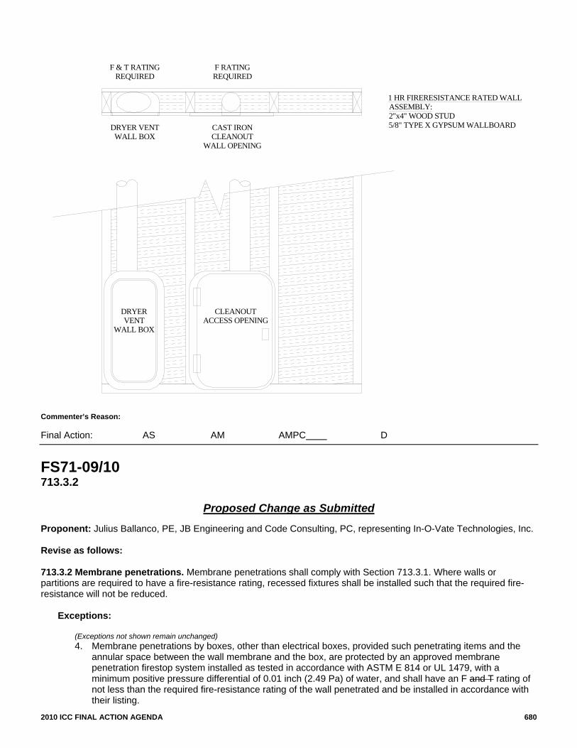
2010 ICC FINAL ACTION AGENDA 680
1 HR FIRERESISTANCE RATED WALLASSEMBLY:2"x4" WOOD STUD5/8" TYPE X GYPSUM WALLBOARDDRYER VENT
WALL BOX
DRYERVENT
WALL BOX
CLEANOUTACCESS OPENING
CAST IRONCLEANOUT
WALL OPENING
F & T RATINGREQUIRED
F RATINGREQUIRED
Commenter=s Reason: Final Action: AS AM AMPC D
FS71-09/10 713.3.2
Proposed Change as Submitted
Proponent: Julius Ballanco, PE, JB Engineering and Code Consulting, PC, representing In-O-Vate Technologies, Inc. Revise as follows: 713.3.2 Membrane penetrations. Membrane penetrations shall comply with Section 713.3.1. Where walls or partitions are required to have a fire-resistance rating, recessed fixtures shall be installed such that the required fire-resistance will not be reduced.
Exceptions:
(Exceptions not shown remain unchanged) 4. Membrane penetrations by boxes, other than electrical boxes, provided such penetrating items and the
annular space between the wall membrane and the box, are protected by an approved membrane penetration firestop system installed as tested in accordance with ASTM E 814 or UL 1479, with a minimum positive pressure differential of 0.01 inch (2.49 Pa) of water, and shall have an F and T rating of not less than the required fire-resistance rating of the wall penetrated and be installed in accordance with their listing.

2010 ICC FINAL ACTION AGENDA 681
Reason: I submitted this change to the last cycle when the “T rating” was added to the membrane box penetration. This was not a requirement in the 2006 edition of the IBC. Traditionally, the IBC has never required a “T rating” for horizontal penetrations. This is the first requirement for such a rating.
It is my opinion that the code should be consistent. I have submitted another change that adds the “T rating” for all horizontal penetrations. Either all horizontal penetrations or no horizontal penetrations should be required to have a “T rating.” The code cannot be inconsistent. Cost Impact: The code change proposal will not increase the cost of construction.
ICCFILENAME: BALLANCO-FS2-713.3.2.doc
Public Hearing Results Committee Action: Disapproved Committee Reason: The committee felt that the T-rating for the items described in item 4 of 713.3.2 was appropriate and was cost effective to achieve during the testing of the boxes and therefore should remain as a requirement. Assembly Action: None
Individual Consideration Agenda
This item is on the agenda for individual consideration because a public comment was submitted. Public Comment: Julius Balance, PE, JB Engineering and Code Consulting, PC, representing In-O-Vate Technologies, requests Approval as Submitted. Commenter=s Reason: The Committee failed to address the single concern that I raised with Code Change F71-09/10. That concern is, “Why does the code require a “T” rating for a box penetrating a wall while not requiring a “T” rating for any other wall penetration? Either a “T” rating is appropriate or it is not. I have included a drawing of the absurdity of the current code requirement. If a dryer vent box is located in a 1 hour wall, the box penetration must have an F and T rating. Right alongside the dryer vent box, a cleanout wall opening to a cast iron pipe is shown. That opening only requires an F rating. Yet, the hazard is the same for both openings. Anything you say about the one opening, you can say about the other opening. This is true for so many other wall penetrations that are not boxes. So, the real question is, do we need a T rating (in addition to an F rating) for wall penetrations? I do not believe we do. That is why I would encourage the membership to vote to approve Code Change F71-09/10. If the membership believes a T rating is necessary, then I have provided that opportunity with Code Change F70-09/10.
1 HR FIRERESISTANCE RATED WALLASSEMBLY:2"x4" WOOD STUD5/8" TYPE X GYPSUM WALLBOARDDRYER VENT
WALL BOX
DRYERVENT
WALL BOX
CLEANOUTACCESS OPENING
CAST IRONCLEANOUT
WALL OPENING
F & T RATINGREQUIRED
F RATINGREQUIRED
Final Action: AS AM AMPC D

2010 ICC FINAL ACTION AGENDA 682
FS72-09/10 713.2 (New)
Proposed Change as Submitted
Proponent: William E. Koffel, Koffel Associates, Inc, representing Firestop Contractors International Association Add new text as follows: 713.2 Contractor Qualifications. In buildings having occupied floors located more than 75 feet (22860 mm) above the lowest level of fire department vehicle access, through-penetration firestop systems shall be installed by contractors that are approved or qualified for such installations under programs administered by approved agencies, such as FM Approvals or Underwriters Laboratories. (Renumber subsequent sections) Reason: Proper Design, Installation, Inspection and Maintenance of Firestop Systems is critical to fire and life safety in buildings because firestopping is used in everything from egress corridors to separation of spaces. Firestopping is a highly technical industry, requiring specialized knowledge at the firestop contracting firm in the office and field to analyze conditions on construction documents and / or on-site, select the appropriate firestop system(s) from UL, FM, Intertek and other directories, then match the systems to penetrating items and annular spaces as they exist in the field, with no variances from the systems allowed. If the system is not installed to the parameters in the design, the ‘system’ may or may not work when called upon by fire. This code change proposal addresses installation of through penetration and membrane firestop systems to zero-tolerance parameters of the classified and listed firestop design. The concept has been proposed in the past and some felt the scope was too broad. Therefore, the scope of the proposed requirement has been limited to high-rise buildings. There are approval or qualification programs administered by approved agencies such as FM Approvals and Underwriters Laboratories for contractors who install materials that become firestop systems. Any contractor (trade or specialty firestop contractor) installing firestop systems can be approved or qualified to the programs administered by these agencies. The programs are similar to ISO 9000 that is used for the manufacturing environment, but adjusted for the construction environment. Successful completion means that the company has policies and procedures in place sufficient to control operations resulting in installations conforming to the listed firestop system. Any firm is eligible to obtain FM Approval and or UL Qualification. With costs ranging from $6000 to $10000 for the initial audit and about $3000 annually for ongoing audits by UL & FM, the cost is less than many contractors would spend on advertising in the “Blue Book” or in entertainment. Experience shows that the cost can be recovered through the benefits of improved processes and reduced errors on firestopping projects. Firestopping by a contractor firm who has been approved or qualified means that the firm has the processes in place in the company culture to handle the zero tolerance installation program needed for firestop systems for fire and life safety. The audits by FM & UL test the company’s ability to install fire and life safety through penetration firestop systems to these requirements, through extensive review of the company procedures. Below is a summary of what it takes for a contractor company to become FM 4991 Approved and / or UL Qualified: -Designated Responsible Individual (DRI) – Each firm employs a DRI who has passed an industry exam based on the Firestop Contractors International Association’s Firestop Industry Manual of Practice, FM Standard FM 4991, Standard for the Approval of Firestop Contractors, and - or the UL Qualified Firestop Contractor Program requirements, as well as selection of firestop systems from directories matched to field conditions. -Quality Audits – FM & UL then audit the firestop processes of the company: --Initial Audit - The process to install firestopping is very technical, and needs attention to detail. The specialty firestop contractor firm or trade contractor firm has their company quality manual audited and approved or qualified by an auditor from either FM Approvals or Underwriters Laboratories to be recognized by the approved agency as a ‘certified contractor’. This is a very robust, truly independent inspection of the contractors’ firestop systems selection, submittal, and installation and inspection processes by FM & UL Auditors. Auditors also visit a project site to verify that the procedures are actually in place throughout the company. Audits of the company include every discipline from training of employees, systems selection and communications to – from the field. --Annual Audit – FM and or UL visit the firm to review the company’s procedures annually to verify continued compliance to the FM 4991 Standard or UL Qualified Firestop Contractor Program. These visits are key to continued success of the firm’s quality management system. Firestopping is a vital part of effective compartmentation. When installation is not performed correctly, it can cause delays of certificate of occupancy, reducing building owners’ revenue streams and create a fire and life safety risk. FM Approved and UL Qualified Firestop Contractors can lower the risk of non compliant firestopping through a company culture that has embraced the quality management system approach through their company culture. Firestopping installation is a process that is knowledge sensitive, and requires a company (not just a worker) that has the quality management systems culture ingrained in it’s operations and, more importantly, it’s people. Plus, the production of the quality assurance manual at the company helps them gather important insight into company operations through self assessment followed up by a full audit by a credible, independent organization, FM & UL There are many contractor firms who have been approved or qualified, that cover most of the US, Dubai, with many more in process of becoming approved or qualified throughout the world. Since firestopping is lightweight, and knowledge travels, so too can FM Approved and UL Qualified Firestop Contractor Firms travel to serve local needs competitively, throughout North America. Contractors have even exported the process know how to the Middle East including the United Arab Emirates, and beyond. For more information, visit http://www.fcia.org to view Specialty Firestop Contractor Firms who have become FM 4991 Approved or UL Qualified, and see the approval and qualification documents to understand how the contractor company can get involved in the programs. Cost Impact: The code change proposal will not increase the costs of construction.
ICCFILENAME: KOFFELL-FS5-713.2 NEW
2010 ICC FINAL ACTION AGENDA 683
Public Hearing Results Committee Action: Disapproved Committee Reason: The committee felt that there was a concern over the availability of approved contractors to provide these installations nation-wide. Further, the term “approved agency” puts the responsibility on the code official to approve these agencies, which in many cases they are not qualified to do. Assembly Action: None
Individual Consideration Agenda
This item is on the agenda for individual consideration because a public comment was submitted. Public Comment: William E. Koffel, PE, Koffel Associates, Inc., representing Firestop Contractors International Association (FCIA), requests Approval as Modified by this Public Comment. Replace the proposal as follows: 713.2 Contractor Qualifications. In buildings having a building height of 420 feet (128 m) or more, through-penetration firestop systems shall be installed by contractors qualified by an approved agency. Exception: Where the work is of a minor nature as approved by the building official. Commenter=s Reason: The language of the proposed Public Comment addresses the issues and concerns of the Code Development Committee 1. Availability of contractors – The application of the section has been restricted to special high-rise buildings and the Code has already established
special requirements for such buildings. As such, there is a higher probability of access to multiple “qualified contractors.” Even if a “qualified contractor” is not immediately available in close proximity to the project, such large projects typically involve special construction teams that draw from a larger geographic area.
2. References to specific qualification programs – The proposed language in the Public Comment eliminates the references to UL and FM and instead used the phrase “approved agency” as defined in Chapter 17 of the Code.
3. Small projects – Just as Chapter 17 allows for special inspections, the proposed exception permits the Building Official to exempt small projects and minor work from the requirement. Proper design, installation, inspection, and maintenance of Firestop Systems is critical to fire and life safety in buildings because firestopping is
used in everything from egress corridors to separation of spaces. Firestopping is a highly technical industry, requiring specialized knowledge at the firestop contracting firm in the office and field to analyze conditions on construction documents and/or on-site, select the appropriate firestop system(s) from UL, FM, Intertek and other directories, then match the systems to penetrating items and annular spaces as they exist in the field, with no variances from the systems allowed. If the system is not installed to the parameters in the design, the ‘system’ may or may not work when called upon by fire. This Public Comment addresses installation of through penetration and membrane firestop systems to zero-tolerance parameters of the classified and listed firestop design. The concept has been proposed in the past and some felt the scope was too broad. Therefore, the scope of the proposed requirement has been limited to certain high-rise buildings.
There are approval or qualification programs administered by approved agencies such as FM Approvals and Underwriters Laboratories for contractors who install materials that become firestop systems. Any contractor (trade or specialty firestop contractor) installing firestop systems can be approved or qualified to the programs administered by these agencies. The programs are similar to ISO 9000 that is used for the manufacturing environment, but adjusted for the construction environment. Successful completion means that the company has policies and procedures in place sufficient to control operations resulting in installations conforming to the listed firestop system.
Any firm is eligible to obtain FM Approval and or UL Qualification. With costs ranging from $6000 to $10000 for the initial audit and about $3000 annually for ongoing audits by UL & FM, the cost is less than many contractors would spend on advertising in the “Blue Book” or in entertainment. Experience shows that the cost can be recovered through the benefits of improved processes and reduced errors on firestopping projects.
Firestopping by a contractor firm who has been approved or qualified means that the firm has the processes in place in the company culture to handle the zero tolerance installation program needed for firestop systems for fire and life safety. The audits by FM & UL test the company’s ability to install fire and life safety through penetration firestop systems to these requirements, through extensive review of the company procedures. Final Action: AS AM AMPC D
2010 ICC FINAL ACTION AGENDA 684
FS74-09/10 713.2.1 (New)
Proposed Change as Submitted
Proponent: William E. Koffel, Koffel Associates, Inc, representing Firestop Contractors International Association Add new text as follows: 713.2 Installation details. Where sleeves are used, they shall be securely fastened to the assembly penetrated. The space between the item contained in the sleeve and the sleeve itself and any space between the sleeve and the assembly penetrated shall be protected in accordance with this section. Insulation and coverings on or in the penetrating item shall not penetrate the assembly unless the specific material used has been tested as part of the assembly in accordance with this section. 713.2.1 Alternative Methods. Where the configuration of a penetrating item or group of items is such that listed penetration firestop system tested in accordance with ASTM E 814 or UL 1479 is determined to be non-existent and reconfiguration of the penetrations or fire resistance rated assembly is determined to be impractical or impossible, alternative methods for maintaining the integrity of the required fire–resistance rating of the assembly shall be permitted to be established by any of the following methods or procedures.
1. Designs documented in approved sources but not in public directories. 2. Calculations performed in an approved manner. 3. Engineering analysis based on a comparison of approved penetration firestop systems tested in accordance
with ASTM E 814 or UL 1479 that extrapolate specific similar features from these systems and combine them to formulate an equivalent fire resistant rated assembly as specifically designated by the manufacturer’s technical representative of the systems specified within the referenced approved penetration firestop system.
4. Alternative protection methods as allowed by Section 104.11 Reason: The purpose of this code change proposal is to clarify a part of the code that is confusing in the field to enforce. Although there are over 8000 classified systems in the Underwriters Laboratories Fire Resistance Directory and thousands more in Intertek, FM Approvals and other laboratories listings, there are still configurations that appear at project sites that have no qualified system listed in a directory. This is when our firestop contracting industry searches for advice from the manufacturers headquarters technical personnel to seek a determination that a combination of systems that closely resembles the situation be suggested for approval from the manufacturer, that is documented by the manufacturer for submittal. This service is performed by manufacturer’s qualified technical personnel who understand the fire performance of these products in systems, and use characteristics found in similar systems to make a determination about suitability for use of the products in the specific application. These suggestions are submitted by firestop manufacturer’s technical staff through the contractor for approval. Using knowledge from those who fire test the products frequently and understand their limitations, these manufacturer’s technical personnel reference the closest possible tested system(s) to determine an appropriate method that provides a system closest to the field condition. This code language is needed to set minimum requirements for how these determinations, (also known as Engineering Judgments, or Equivalent Fire Resistance Rated Assemblies) are created, and who at the company should be responsible for writing these determinations of suitability for use in specific applications. Companies are structured different ways, with many titles for field sales people. Those with the most experience with fire testing products at companies, and the most removed from the sales process seems to be the manufacturer’s technical personnel at headquarters locations. This code language is needed to provide the building official transparency in the process when presented engineering judgments from the industry…only if a listed system cannot be found in the directories from any manufacturer…even if it means switching manufacturers for a few applications. Cost Impact: The code change proposal will not increase the costs of construction. Analysis: Standards ASTM E814 and UL 1479 are currently referenced in the I-codes.
ICCFILENAME: KOFFELL-FS2-713.2.1 NEW
Public Hearing Results Committee Action: Disapproved Committee Reason: The committee felt some of the terms, such as “impractical” and “impossible” were too subjective and difficult to determine. Further, the phrase “calculations performed in an approve manner” is difficult to determine and perhaps unenforceable. Lastly, Section 104.11 already allows for alternative methods. Assembly Action: None

2010 ICC FINAL ACTION AGENDA 685
Individual Consideration Agenda This item is on the agenda for individual consideration because a public comment was submitted. Public Comment: William E. Koffel, PE, Koffel Associates, Inc., representing Firestop Contractors International Association (FICA), requests Approval as Modified by this Public Comment. Modify the proposal as follows: 713.2 Installation details. Where sleeves are used, they shall be securely fastened to the assembly penetrated. The space between the item contained in the sleeve and the sleeve itself and any space between the sleeve and the assembly penetrated shall be protected in accordance with this section. Insulation and coverings on or in the penetrating item shall not penetrate the assembly unless the specific material used has been tested as part of the assembly in accordance with this section. 713.2.1 Alternative Methods. Where the configuration of a penetrating item or group of items is such that listed penetration firestop system tested in accordance with ASTM E 814 or UL 1479 is determined to be non-existent and reconfiguration of the penetrations or fire resistance rated assembly is determined to be impractical or impossible, alternative methods for maintaining the integrity of the required fire–resistance rating of the assembly shall be permitted to be established by any of the following methods or procedures. using an engineering analysis based on a comparison of listed penetration firestop systems and prepared by a manufacturer’s technical representative of the systems specified or prepared by the laboratory that conducted the original test.
1. Designs documented in approved sources but not in public directories. 2. Calculations performed in an approved manner. 3. Engineering analysis based on a comparison of approved penetration firestop systems tested in accordance with ASTM E 814 or UL 1479
that extrapolate specific similar features from these systems and combine them to formulate an equivalent fire resistant rated assembly as specifically designated by the manufacturer’s technical representative of the systems specified within the referenced approved penetration firestop system.
4. Alternative protection methods as allowed by Section 104.11 Commenter=s Reason: The purpose of this Public Comment is to clarify a part of the Code that is confusing in the field to enforce. Although there are over 8000 classified systems in the Underwriters Laboratories Fire Resistance Directory and thousands more in Intertek, FM Approvals and other laboratories listings, there are still configurations that appear at project sites that have no qualified system listed in a directory. This is when the firestop contracting industry searches for advice from the manufacturer’s headquarters technical personnel to seek a determination that a combination of systems that closely resembles the situation be suggested for approval from the manufacturer.
This service is to be performed by manufacturer’s qualified technical personnel who understand the fire performance of these products in systems or a representative of the testing laboratory, and use characteristics found in similar systems to make a determination about suitability for use of the products in the specific application. These suggestions are submitted by firestop manufacturer’s technical staff through the contractor for approval. Using knowledge from those who fire test the products frequently and understand their limitations, the manufacturer’s technical personnel reference the closest possible tested system(s) to determine an appropriate method that provides a system closest to the field condition.
This Code language is needed to set minimum requirements for when these determinations are permitted to be used, how these determinations (also known as Engineering Judgments, or Equivalent Fire Resistance Rated Assemblies) are created, and who should be responsible for writing these determinations of suitability for use in specific applications.
Companies are structured different ways, with many titles for field sales people. Those with the most experience with fire testing products at companies, and the most removed from the sales process seems to be the manufacturer’s technical personnel at headquarters locations. This Code language is needed to provide the building official transparency in the process when presented engineering judgments from the industry…only if a listed system cannot be found in the directories from any manufacturer…even if it means switching manufacturers for a few applications.
During the Public Hearings various comments were raised ranging from this is desperately needed in the field to such language will encourage the further use of engineering judgments. By restricting the application to instances for which a listed system does not exist and who may prepare the engineering judgment we do not believe that the further use of engineering judgments will be encouraged. Although the Code will now specifically permit engineering judgments, something permitted today by the Code as an alternative method, most manufacturers will continue to test applications that are commonly used in the field since there is still a cost involved in preparing engineering judgments and the use of engineering judgments has the potential to increase the construction time due to the specific approval required for an engineering judgment.
In summary, the Public Comment simplifies the verbiage that was originally proposed in the Public Proposal. Furthermore, the verbiage of the Public Comment restricts the use of engineering judgments to those instances for which a listed system does not exist by any manufacturer. Lastly, the Public Comment retains the original concept that the engineering judgment must be prepared by someone who is familiar with the testing that has been performed. Final Action: AS AM AMPC D

2010 ICC FINAL ACTION AGENDA 686
FS75-09/10 713.4.1.2
Proposed Change as Submitted
Proponent: Tim Pate, City and County of Broomfield, representing the Colorado Chapter ICC Code Change Committee Revise as follows: 713.4.1.2 Membrane penetrations. Penetrations of membranes that are part of a horizontal assembly shall comply with Sections 713.4.1.1.1 or 713.4.1.1.2. Where floor/ceiling assemblies are required to have a fire resistance rating, recessed fixtures shall be installed such that the required fire resistance will not be reduced. Exceptions: (Exceptions 1-5 remain unchanged)
6. The ceiling membrane of 1 and 2 hour fire resistance rated horizontal assemblies is permitted to be interrupted with the double wood top plate of a fire resistance wall assembly provided that all penetrating items through the double top plates are protected in accordance with Section 713.4.1.1.1 or 713.4.1.1.2.
Reason: This code change will add a new exception to section 712.4.1.2 which will allow the ceiling membrane of a 1 or 2 hour fire rated floor/ceiling or roof/ceiling assembly to be interrupted by a double wood top plate of a fire rated wall. All penetrations of the top plates would have to be protected by approved through penetration firestop systems. This would codify the typical construction that we see with Type VA construction where the wood framed walls extend up and attach directly to the underside of wood floor joists/trusses or roof joists/trusses for structural requirements. Non fire rated wall top plates would not be allowed to interrupt the drywall membrane of the floor/ceiling or roof/ceiling. Section 711.4 would technically require this ceiling membrane to be continuous in these areas but it would be impossible to install this drywall on top of load bearing walls since the drywall would end up being crushed when building is fully loaded. This code change would get the IBC in line with the UL testing criteria and general notes. This code change would allow what we already see on every Type VA building. Cost Impact: The code change proposal will not increase the cost of construction.
ICCFILENAME: PATE-FS1-713.4.1.2
Public Hearing Results
Committee Action: Disapproved Committee Reason: The committee felt that the ceiling membrane should be continuous and uninterrupted; however if this proposal were to be considered it should be limited to nonfireresistance rated partitions or fire partitions. Assembly Action: None
Individual Consideration Agenda
These items are on the agenda for individual consideration because public comments were submitted. Public Comment 1: George Kellogg, Rocklin, CA, representing Sacramento Valley Association of Building Officials, requests Approval as Submitted. Commenter=s Reason: The proposed code change would codify the practical application of the code by clarifying that ceiling membrane of 1 and 2 hour fire-rated ceilings may be interrupted by the double top-plate of a supporting wall so long as penetrations are treated with appropriate fire stop assemblies. This proposal would allow for continuity of structural systems with the proper application of Section 713.4.1.1.1 or 713.4.1.1.2.

2010 ICC FINAL ACTION AGENDA 687
Public Comment 2: Tim Pate representing the Colorado Chapter of ICC, requests Approval as Modified by this Public Comment. Modify the proposal as follows: 713.4.1.2 Membrane penetrations. Penetrations of membranes that are part of a horizontal assembly shall comply with Sections 713.4.1.1.1 or 713.4.1.1.2. Where floor/ceiling assemblies are required to have a fire resistance rating, recessed fixtures shall be installed such that the required fire resistance will not be reduced.
Exceptions:
(Exceptions 1-5 remain unchanged) 6. The ceiling membrane of 1 and 2 hour fire resistance rated horizontal assemblies is permitted to be interrupted with the double wood
top plate of a fire resistance wall assembly, provided that all penetrating items through the double top plates are protected in accordance with Section 713.4.1.1.1 or 713.4.1.1.2. The fire resistance rating of the wall shall not be less than the rating of the horizontal assembly.
Commenter=s Reason: There was testimony in opposition to the original code change that this new exception could potentially allow a fire barrier to not be continuous through the fire resistance rated horizontal assembly. We respectfully disagree since Section 707.5 Continuity of Fire Barriers specifically requires these assemblies to be continuous to the under side of the floor or roof sheathing, slab or deck above. This would super cede this new exception since it is the more restrictive requirement. Section 709.4 Continuity of Fire Partitions has same language but allows them to stop at bottom membrane of horizontal assembly as long as there is adequate fire blocking or draftstopping above and within the interstitial space. As described in the original reason statement this code change will allow the two top plates to become equivalent to the ceiling membranes of either the one or two hour rated assembly. I have added language to clarify that the rating of the wall would need to match the rating of the horizontal – one hour wall for one hour assembly and two hour wall for two hour assembly. This exception would then only deal with the fire partitions and interior bearing walls based on the Table 601 requirements. Public Comment 3: Bruce Dimmig and Tom Hedges, Mesa, AZ, representing the Arizona Building Officials, requests Approved as Modified by this public comment. Modify the proposal as follows: 713.4.1.2 Membrane penetrations. Penetrations of membranes that are part of a horizontal assembly shall comply with Sections 713.4.1.1.1 or 713.4.1.1.2. Where floor/ceiling assemblies are required to have a fire resistance rating, recessed fixtures shall be installed such that the required fire resistance will not be reduced.
Exceptions: (Exceptions 1-5 remain unchanged) 6. The ceiling membrane of 1 and maximum 2-hour fire resistance rated horizontal assemblies is permitted to be interrupted with the double
wood top plate of a fire resistance rated wall assembly, having an equal or greater fire resistance rating than the horizontal assembly, provided that all penetrating items through the double top plates are protected in accordance with Section 713.4.1.1.1 or 713.4.1.1.2.
Commenter=s Reason: The committee reason that the ceiling membrane should be continuous and uninterrupted is not practical or possible as the existing exceptions demonstrate. Section 711.4 would technically require this ceiling membrane to be continuous in these areas but it would be impossible to install this drywall on top of load bearing walls or shear walls since the drywall would end up being crushed when building is fully loaded. A fire resistance rated wall could be of wood, masonry or steel. By stipulating a rating for the walls that can penetrate the ceiling membrane, a safe level of fire resistance will be provided. If the ceiling membrane is not permitted to be interrupted by walls, the following Fig. 1 and 2 examples of typical construction would no longer be permitted.

2010 ICC FINAL ACTION AGENDA 688
FIG. 1
FIG. 2
Final Action: AS AM AMPC D

2010 ICC FINAL ACTION AGENDA 689
FS76-09/10 713.4.2.3 (New)
Proposed Change as Submitted
Proponent: William E. Koffel, Koffel Associates, Inc, representing Firestop Contractors International Association 1. Revise as follows: 713.4.2 Nonfire-resistance-rated assemblies. Penetrations of nonfire-resistance-rated floor or floor/ceiling assemblies or the ceiling membrane of a nonfire-resistance-rated roof/ceiling assembly shall meet the requirements of Section 708 or shall comply with Section 713.4.2.1 or , 713.4.2.2., or 713.4.2.3. 713.4.2.1 Noncombustible penetrating items. Noncombustible penetrating items that connect not more than three stories are permitted, provided that the annular space is filled to resist the free passage of flame and the products of combustion with an approved noncombustible material or with a fill, void or cavity material that is tested and classified for use in through-penetration firestop systems. 712.4.2.2 Penetrating items. Penetrating items that connect not more than two stories are permitted, provided that the annular space is filled with an approved material to resist the free passage of flame and the products of combustion. 2. Add new text as follows: 713.4.2.3 Unlimited stories. Penetrating items shall be permitted provided the annular space is filled with a fill, void, cavity material, or device that is tested and classified for use in through-penetration firestop systems. Reason: Currently the Code limits the number of stories connected without a shaft when the floor is not required to have a fire resistance rating. The Code currently permits the use of approved materials. While fill, void, or cavity materials and devices tested for use in through penetration firestop systems would likely be approved materials, the proposed language clearly states that such materials shall be permitted without specific approval. The proposed language will also allow such materials without a height restriction. However, Table 503 limits most buildings with non-rated floor assemblies to heights less than three stories unless an automatic sprinkler system is provided. A void or cavity material that is tested and classified for use in through penetration firestop systems is an effective method for preventing the passage of fire and toxic gas. Very often this limitation in the code relating to the number of stories of penetrating items is overlooked because the floor is not required to be fire resistant and as a result penetrations are left inadequately protected. To require a shaft enclosure for what could be a very limited quantify of penetrations of a non-rated floor assembly is excessive when other acceptable means to protect the penetrations are available. Cost Impact: Much more cost effective methodology.
ICCFILENAME: KOFFELL-FS8-713.4.2 NEW
Public Hearing Results
Committee Action: Disapproved Committee Reason: Disapproval was requested by the proponent based on the committee’s action on FS56-09/10. Assembly Action: None

2010 ICC FINAL ACTION AGENDA 690
Individual Consideration Agenda This item is on the agenda for individual consideration because a public comment was submitted. Public Comment: William E. Koffel, PE, Koffel Associates, Inc., representing Firestop Contractors International Association (FCIA), requests Approval as Modified by this Public Comment. Modify the proposal as follows: 713.4.2 Nonfire-resistance-rated assemblies. Penetrations of nonfire-resistance-rated floor or floor/ceiling assemblies or the ceiling membrane of a nonfire-resistancerated roof/ceiling assembly shall meet the requirements of Section 708 or shall comply with Section 713.4.2.1 or 713.4.2.2, or 713.4.2.3. 713.4.2.1 Noncombustible penetrating items. Noncombustible penetrating items that connect not more than three five stories are permitted, provided that the annular space is filled to resist the free passage of flame and the products of combustion with an approved noncombustible material or with a fill, void, or cavity material, or device that is tested and classified for use in through-penetration firestop systems. 713.4.2.2 Penetrating items. Penetrating items that connect not more than two stories are permitted, provided that the annular space is filled with an approved material to resist the free passage of flame and the products of combustion. 713.4.2.3 Unlimited stories Combustible penetrating items. Combustible penetrating items that connect not more than five stories shall be permitted, provided the annular space is filled with a fill, void, or cavity material, or device that is tested and classified for use in through-penetration firestop systems. Commenter=s Reason: With the action taken on FS56-09/10, noncombustible penetrating items are permitted to connect up to five stories without a shaft enclosure when the horizontal assembly is not required to have a fire resistance rating. Combustible and noncombustible penetrations are permitted to connect two stories and only be protected by an approved material to fill the annual space. The Code makes no reference to the use of a fill, void, or cavity material or a device for combustible penetrations other than to presume they would be an “approved material” as required in 713.4.2.2.
The FCIA submitted proposal FS76-09/10 that would also allow the use of a fill, void, or cavity material or device for combustible penetrations. FS76-09/10 was recommended for Disapproval based upon the action taken on FS56-09/10. However, FS56-09/10 did not address combustible penetrations connecting more than two stories. The purpose of this Public Comment is to extend the permitted use of fill, void, or cavity materials materials or devices to protect non-rated floors for both combustible and noncombustible penetrations.
A fill, void or cavity material or a device that is tested and classified for use in through penetration firestop systems is an effective method for preventing the passage of fire and toxic gas. Very often this limitation in the code relating to the number of stories of combustible penetrating items is overlooked because the floor is not required to be fire resistant and as a result penetrations are left inadequately protected.
To require a shaft enclosure for what could be a very limited quantity of penetrations of a non-rated floor assembly is excessive when other acceptable means to protect the penetrations are available.
The change from three stories to five stories in 713.4.2.1 is consistent with the action taken on FS56-09/10. Although we would agree that the three paragraphs could be sequenced better, the language in the Public Comment has been formatted so that it can be incorporated into the action on FS56-09/10 by only changing the section numbers from 713.4.2 to 714.4.2. Final Action: AS AM AMPC D
FS81–09/10 714.1
Proposed Change as Submitted Proponent: Jesse J. Beitel, Hughes Associates, Inc., representing Metal Building Manufacturers Association Revise as follows: 714.1 General. Joints installed in or between fire-resistance-rated walls, floor or floor/ceiling assemblies and roofs or roof/ceiling assemblies shall be protected by an approved fire-resistant joint system designed to resist the passage of fire for a time period not less than the required fire-resistance rating of the wall, floor or roof in or between which it is installed. Fire-resistant joint systems shall be tested in accordance with Section 714.3. The void created at the intersection of a floor/ceiling assembly and an exterior curtain wall assembly shall be protected in accordance with Section 714.4.

2010 ICC FINAL ACTION AGENDA 691
Exceptions:
1. Fire-resistant joint systems shall not be required for joints in all of the following locations: 1.1. Floors within a single dwelling unit. 1.2. Floors where the joint is protected by a shaft enclosure in accordance with Section 708. 1.3. Floors within atriums where the space adjacent to the atrium is included in the volume of the atrium
for smoke control purposes. 1.4. Floors within malls. 1.5. Floors and ramps within open and enclosed parking garages or structures constructed in
accordance with Sections 406.3 and 406.4, respectively. 1.6. Mezzanine floors. 1.7. Walls that are permitted to have unprotected openings. 1.8. Roofs where openings are permitted. 1.9. Control joints not exceeding a maximum width of 0.625 inch (15.9 mm) and tested in accordance
with ASTM E 119 or UL 263. 2. The voids created at the intersection of a fire-resistance-rated wall assembly and a non-fire-resistance-
rated roof assembly shall be filled, but are not required to comply with the requirements of this section. The material or system used to fill the void shall be securely installed in or on the intersection for its entire length so as not to dislodge, loosen or otherwise impair its ability to accommodate expected building movements and to retard the passage of fire and hot gases.
Reason: The IBC defines joints as being an opening that occurs between two fire-resistance rated assemblies. However, in many instances there are openings/void spaces that occur between a fire-resistance rated assembly and a non-fire resistance rated assembly. One very common type of this situation occurs when a fire-resistance rated wall assembly terminates at the underside of a non-fire-resistance rated roof assembly in a low-rise metal building. This code change proposal has been submitted so as to clarify the requirements for these types of situations. The Metal Building Manufacturers Association requested a formal interpretation on this matter. Interpretation 34-08 dated February 20, 2009 states that Section 713.1 (2006 edition) did not apply to these intersections. Thus, this Code proposal is just adding new language to address the findings of the Code interpretation and therefore enhance the code. It is understood that this new Exception does not remove the continuity requirements for these types of assemblies as specified in the appropriate Sections of the Code. Also, the industry has specifically inserted the requirements for installation so as to address the proper installation of the materials and systems used in this application. Cost Impact: The code change proposal will not increase the cost of construction.
ICCFILENAME: BEITEL-FS3-714.1.doc
Public Hearing Results
Committee Action: Disapproved Committee Reason: The committee felt that the exception was in the wrong place and would be better located in the continuity provisions. Also, the committee felt there should be some referenced to an acceptable material to used to fill the void in question. Assembly Action: None
Individual Consideration Agenda This item is on the agenda for individual consideration because a public comment was submitted. Public Comment: Jesse J. Beitel, Hughes Associates, Inc., representing Metal Building Manufacturers Association, requests Approval as Modified by this Public Comment. Replace the proposal as follows: 707.5 Continuity. Fire barriers shall extend from the top of the floor/ceiling assembly below to the underside of the floor or roof sheathing, slab or deck above and shall be securely attached thereto. Such fire barriers shall be continuous through concealed space, such as the space above a suspended ceiling. Joints and voids at intersections shall comply with Section 707.8 and 707.9. 707.8 Joints. Joints made in or between fire barriers and joints at the intersection of fire barriers with the underside of a fire-resistance-rated the floor or roof sheathing, slab or deck above, shall comply with Section 714.

2010 ICC FINAL ACTION AGENDA 692
707.9 Voids At Intersections. The voids created at the intersection of a fire barrier and a non-fire-resistance-rated roof assembly shall be filled. An approved material or system shall be used to fill the void, shall be securely installed in or on the intersection for its entire length so as not to dislodge, loosen or otherwise impair its ability to accommodate expected building movements and to retard the passage of fire and hot gases. (Renumber subsequent section) Commenter=s Reason: This modified language addresses comments made by the Committee and others at the CDH. The basic language from our Proposal remains but the modification to the proposal addresses the concern of the appropriate location for this provision that addresses voids at the intersection of fire barriers and non-fire-resistance-rated roofs. The new Section 707.9 will provide the requirements. The additional language in Section 707.5 provides a pointer to the new Section and the new language in section 707.8 provides clarification. Additionally, the proposal requires that the material or system be approved. Thus, documentation to show that material or system will meet the performance requirements to retard the passage of fire and hot gases must be provided. The Metal Building Manufacturers Association (MBMA) has performed this type of testing and the information including UL’s test reports can be found at MBMA.com and follow the links to Technical Library, Fire Resistance, Head of Wall. Note to Staff: If FS56-09/10 is approved, wording of “voids at intersections” could be changed to ‘joints”. Final Action: AS AM AMPC D
FS83-09/10 714.1.1 (New)
Proposed Change as Submitted
Proponent: William E. Koffel, Koffel Associates, Inc, representing Firestop Contractors International Association Add new text as follows: 714.1 General. Joints installed in or between fire-resistance- rated walls, floor or floor/ceiling assemblies and roofs or roof/ceiling assemblies shall be protected by an approved fire-resistant joint system designed to resist the passage of fire for a time period not less than the required fire-resistance rating of the wall, floor or roof in or between which it is installed. Fire-resistant joint systems shall be tested in accordance with Section 714.3. The void created at the intersection of a floor/ceiling assembly and an exterior curtain wall assembly shall be protected in accordance with Section 714.4. Exception: Fire-resistant joint systems shall not be required for joints in all of the following locations:
1. Floors within a single dwelling unit. 2. Floors where the joint is protected by a shaft enclosure in accordance with Section 708. 3. Floors within atriums where the space adjacent to the atrium is included in the volume of the atrium for
smoke control purposes. 4. Floors within malls. 5. Floors and ramps within open and enclosed parking garages or structures constructed in accordance with
Sections 406.3 and 406.4, respectively. 6. Mezzanine floors. 7. Walls that are permitted to have unprotected openings. 8. Roofs where openings are permitted. 9. Control joints not exceeding a maximum width of 0.625 inch (15.9 mm) and tested in accordance with
ASTM E 119 or UL 263. 714.1.1 Alternative Methods. Where the configuration of a joint is such that a listed joint firestop system or perimeter fire containment system tested in accordance with ASTM E 1966 or UL 2079 or ASTM E 2307, is determined to be non-existent alternative methods for maintaining the integrity of the required fire–resistance rating of the assembly shall be permitted to be established by any of the following methods or procedures.
1. Designs documented in approved sources but not in public directories. 2. Calculations performed in an approved manner. 3. Engineering analysis based on a comparison of approved penetration firestop systems tested in accordance
with ASTM E 1966 or UL 2079 and or ASTM E 2307 that extrapolate specific similar features from these systems and combine them to formulate an equivalent fire resistant rated assembly as specifically designated by the manufacturer’s technical representative of the systems specified within a referenced approved penetration firestop system
4. Alternative protection methods as allowed by Section 104.11

2010 ICC FINAL ACTION AGENDA 693
Reason: The purpose of this code change proposal is to clarify a part of the code that is confusing in the field to enforce. Although there are over 8000 classified systems in the Underwriters Laboratories Fire Resistance Directory and thousands more in Intertek, FM Approvals and other laboratories listings, there are still configurations that appear at project sites that have no qualified system listed in a directory. This is when the firestop contracting industry searches for advice from the manufacturer’s technical personnel to seek a determination that a combination of systems that closely resembles the situation be suggested for approval based upon documentation from the manufacturer. This service is performed by manufacturer’s qualified technical personnel who understand the fire performance of these products in systems, and use characteristics found in similar systems to make a determination about suitability for use of the products in the specific application. These suggestions are submitted by firestop manufacturer’s technical staff through the contractor for approval. Using knowledge from those who fire test the products frequently and understand their limitations, these manufacturers technical personnel reference the closest possible tested system(s) to determine an appropriate method that provides a system closest to the field condition. This code language is needed to set minimum requirements for how these determinations, (also known as Engineering Judgments, or Equivalent Fire Resistance Rated Assemblies) are created, and who at the company should be responsible for writing these determinations of suitability for use in specific applications. Companies are structured different ways, with many titles for field sales people. Those with the most experience with fire testing products at companies, and the most removed from the sales process seem to be the manufacturers technical personnel often located at headquarter locations. This code language is needed to provide the building official transparency in the process when presented engineering judgments from the industry…only if a listed system cannot be found in the directories from any manufacturer…even if it means switching manufacturers for a few applications. Cost Impact: The code change proposal will not increase the costs of construction.
ICCFILENAME: KOFFELL-FS3-714.1.1 NEW
Public Hearing Results
Committee Action: Disapproved Committee Reason: The committee felt the phrase “calculations performed in an approve manner” is difficult to determine and perhaps unenforceable. Further, Section 104.11 already allows for alternative methods. Assembly Action: None
Individual Consideration Agenda This item is on the agenda for individual consideration because a public comment was submitted. Public Comment: William E. Koffel, PE, Koffel Associates, representing Firestop Contractors International Association (FCIA), requests Approved as Modified by this Public Comment. Modify the proposal as follows: 714.1.1 Alternative Methods: Where the configuration of a joint is such that a listed joint firestop system or perimeter fire containment system tested in accordance with ASTM E 1966 or UL 2079 or ASTM E 2307 is determined to be non-existent, alternative methods for maintaining the integrity of the required fire–resistance rating of the assembly shall be permitted to be established by any of the following methods or procedures using an engineering analysis based on a comparison of listed systems that is prepared by a manufacturer’s technical representative of the systems specified or prepared by the laboratory that conducted the original test.
1. Designs documented in approved sources but not in public directories. 2. Calculations performed in an approved manner. 3. Engineering analysis based on a comparison of approved penetration firestop systems tested in accordance with ASTM E 1966 or UL
2079 and or ASTM E 2307 that extrapolate specific similar features from these systems and combine them to formulate an equivalent fire resistant rated assembly as specifically designated by the manufacturer’s technical representative of the systems specified within a referenced approved penetration firestop system
4. Alternative protection methods as allowed by Section 104.11 Commenter=s Reason: The purpose of this Public Comment is to clarify a part of the Code that is confusing in the field to enforce. Although there are over 8000 classified systems in the Underwriters Laboratories Fire Resistance Directory and thousands more in Intertek, FM Approvals and other laboratories listings, there are still configurations that appear at project sites that have no qualified system listed in a directory. This is when the firestop contracting industry searches for advice from the manufacturer’s headquarters technical personnel to seek a determination that a combination of systems that closely resembles the situation be suggested for approval from the manufacturer.
This service is to be performed by manufacturer’s qualified technical personnel who understand the fire performance of these products in systems or a representative of the testing laboratory, and use characteristics found in similar systems to make a determination about suitability for use of the products in the specific application. These suggestions are submitted by firestop manufacturer’s technical staff through the contractor for approval. Using knowledge from those who fire test the products frequently and understand their limitations, the manufacturer’s technical personnel reference the closest possible tested system(s) to determine an appropriate method that provides a system closest to the field condition.
This Code language is needed to set minimum requirements for when these determinations are permitted to be used, how these determinations (also known as Engineering Judgments, or Equivalent Fire Resistance Rated Assemblies) are created, and who should be responsible for writing these determinations of suitability for use in specific applications.

2010 ICC FINAL ACTION AGENDA 694
Companies are structured different ways, with many titles for field sales people. Those with the most experience with fire testing products at companies, and the most removed from the sales process seems to be the manufacturer’s technical personnel at headquarters locations. This Code language is needed to provide the building official transparency in the process when presented engineering judgments from the industry…only if a listed system cannot be found in the directories from any manufacturer…even if it means switching manufacturers for a few applications.
During the Public Hearings various comments were raised ranging from this is desperately needed in the field to such language will encourage the further use of engineering judgments. By restricting the application to instances for which a listed system does not exist and who may prepare the engineering judgment we do not believe that the further use of engineering judgments will be encouraged. Although the Code will now specifically permit engineering judgments, something permitted today by the Code as an alternative method, most manufacturers will continue to test applications that are commonly used in the field since there is still a cost involved in preparing engineering judgments and the use of engineering judgments has the potential to increase the construction time due to the specific approval required for an engineering judgment.
In summary, the Public Comment simplifies the verbiage that was originally proposed in the Public Proposal. Furthermore, the verbiage of the Public Comment restricts the use of engineering judgments to those instances for which a listed system does not exist by any manufacturer. Lastly, the Public Comment retains the original concept that the engineering judgment must be prepared by someone who is familiar with the testing that has been performed. Final Action: AS AM AMPC D FS86-09/10 714.2.1 (New)
Proposed Change as Submitted
Proponent: William E. Koffel, Koffel Associates, Inc., representing Firestop Contractors International Association Add new text as follows: 714.2 Installation. Fire-resistant joint systems shall be securely installed in or on the joint for its entire length so as not to dislodge, loosen or otherwise impair its ability to accommodate expected building movements and to resist the passage of fire and hot gases. 714.2.1 Installation details, field installation. In buildings having occupied floors located more than 75 feet (22860 mm) above the lowest level of fire department vehicle access, fire-resistant joint systems shall be installed by contractors that are approved or qualified for such installations under programs administered by approved agencies, such as FM Approvals or Underwriters Laboratories. Reason: Proper Design, Installation, Inspection and Maintenance of Joint Systems is critical to fire and life safety in building. This is a highly technical industry, requiring specialized knowledge at the firestop contracting firm in the office and field to analyze conditions on construction documents and / or on-site, select the appropriate firestop system(s) from UL, FM, Intertek and other directories, then match the systems to penetrating items and annular spaces as they exist in the field, with no variances from the systems allowed. If the system is not installed to the parameters in the design, the ‘system’ may or may not work when called upon by fire. This code change proposal addresses installation of joint systems to zero-tolerance parameters of the classified and listed design. And, fire-resistant joint systems are very complicated systems, where the contractor firm installing must have special qualifications to accomplish the goal of limiting fire and smoke spread from the compartment of origin. The concept has been proposed in the past and some felt the scope was too broad. Therefore, the scope of the proposed requirement has been limited to high-rise buildings. There are approval or qualification programs administered by approved agencies such as FM Approvals and Underwriters Laboratories for contractors who install materials that become firestop systems. Any contractor (trade or specialty firestop contractor) installing firestop systems can be approved or qualified to the programs administered by these agencies. The programs are similar to ISO 9000 that is used for the manufacturing environment, but adjusted for the construction environment. Successful completion means that the company has policies and procedures in place sufficient to control operations resulting in installations conforming to the listed firestop system. Any firm is eligible to obtain FM Approval and or UL Qualification. With costs ranging from $6000 to $10000 for the initial audit and about $3000 annually for ongoing audits by UL & FM, the cost is less than many contractors would spend on advertising in the “Blue Book” or in entertainment. Experience shows that the cost can be recovered through the benefits of improved processes and reduced errors on firestopping projects. Firestopping by a contractor firm who has been approved or qualified means that the firm has the processes in place in the company culture to handle the zero tolerance installation program needed for firestop systems for fire and life safety. The audits by FM & UL test the company’s ability to install fire and life safety through penetration firestop systems to these requirements, through extensive review of the company procedures. Below is a summary of what it takes for a contractor company to become FM 4991 Approved and / or UL Qualified: -Designated Responsible Individual (DRI) – Each firm employs a DRI who has passed an industry exam based on the Firestop Contractors International Association’s Firestop Industry Manual of Practice, FM Standard FM 4991, Standard for the Approval of Firestop Contractors, and - or the UL Qualified Firestop Contractor Program requirements, as well as selection of firestop systems from directories matched to field conditions. -Quality Audits – FM & UL then audit the firestop processes of the company: --Initial Audit - The process to install firestopping is very technical, and needs attention to detail.The specialty firestop contractor firm or trade contractor firm has their company quality manual audited and approved or qualified by an auditor from either FM Approvals or Underwriters Laboratories to be recognized by the approved agency as a ‘certified contractor’. This is a very robust, truly independent inspection of the contractors’ firestop systems selection, submittal, and installation and inspection processes by FM & UL Auditors. Auditors also visit a project site to verify that the procedures are actually in place throughout the company. Audits of the company include every discipline from training of employees, systems selection and communications to – from the field. --Annual Audit – FM and or UL visit the firm to review the company’s procedures annually to verify continued compliance to the FM 4991 Standard or UL Qualified Firestop Contractor Program These visits are key to continued success of the firm’s quality management system.
2010 ICC FINAL ACTION AGENDA 695
Firestopping is a vital part of effective compartmentation. When installation is not performed correctly, it can cause delays of certificate of occupancy, reducing building owners’ revenue streams and create a fire and life safety risk. FM Approved and UL Qualified Firestop Contractors can lower the risk of non compliant firestopping through a company culture that has embraced the quality management system approach through their company culture. Firestopping installation is a process that is knowledge sensitive, and requires a company (not just a worker) that has the quality management systems culture ingrained in it’s operations and, more importantly, it’s people. Plus, the production of the quality assurance manual at the company helps them gather important insight into company operations through self assessment followed up by a full audit by a credible, independent organization, FM & UL There are many contractor firms who have been approved or qualified, that cover most of the US, Dubai, with many more in process of becoming approved or qualified throughout the world. Since firestopping is lightweight, and knowledge travels, so too can FM Approved and UL Qualified Firestop Contractor Firms travel to serve local needs competitively, throughout North America. Contractors have even exported the process know how to the Middle East including the United Arab Emirates, and beyond. For more information, visit http://www.fcia.org to view Specialty Firestop Contractor Firms who have become FM 4991 Approved or UL Qualified, and see the approval and qualification documents to understand how the contractor company can get involved in the programs. Cost Impact: There is no cost impact to this code change proposal. Approved or qualified firms assign the correct value to firestopping systems installed to the listed system.
ICCFILENAME: KOFFELL-FS9-714.1
Public Hearing Results
Committee Action: Disapproved Committee Reason: As with FS85-09/10, the committee felt there was a concern over the availability of approved contractors to provide these installations nation-wide. Further, the term “approved agency” puts the responsibility on the code official to approve these agencies, which in many cases they are not qualified to do. Assembly Action: None
Individual Consideration Agenda
This item is on the agenda for individual consideration because a public comment was submitted. Public Comment: William E. Koffel, PE, Koffel Associates, Inc., representing Firestop Contractors International Association (FCIA), requests Approval as Modified by this Public Comment. Replace the proposal as follows: 714.2 Contractor Qualifications. In buildings having a building height of 420 feet (128 m) or more, fire resistant joint systems shall be installed by contractors qualified by an approved agency.
Exception: Where the work is of a minor nature as approved by the building official. Commenter=s Reason: The language of the proposed Public Comment addresses the issues and concerns of the Code Development Committee 1. Availability of contractors – The application of the section has been restricted to special high-rise buildings and the Code has already established
special requirements for such buildings. As such, there is a higher probability of access to multiple “qualified contractors.” Even if a “qualified contractor” is not immediately available in close proximity to the project, such large projects typically involve special construction teams that draw from a larger geographic area.
2. References to specific qualification programs – The proposed language in the Public Comment eliminates the references to UL and FM and instead used the phrase “approved agency” as defined in Chapter 17 of the Code.
3. Small projects – Just as Chapter 17 allows for special inspections, the proposed exception permits the Building Official to exempt small projects and minor work from the requirement. Proper design, installation, inspection and maintenance of joint systems is critical to fire and life safety in building. This is a highly technical
industry, requiring specialized knowledge at the firestop contracting firm in the office and field to analyze conditions on construction documents and / or on-site, select the appropriate fire resistant joint system(s) from UL, FM, Intertek and other directories, then match the systems to conditions as they exist in the field, with no variances from the systems allowed. If the system is not installed to the parameters in the design, the ‘system’ may or may not work when called upon by fire. This Public Comment addresses installation of joint systems to zero-tolerance parameters of the classified and listed design. And, fire-resistant joint systems are very complicated systems, where the contractor firm installing must have special qualifications to accomplish the goal of limiting fire and smoke spread from the compartment of origin. The concept has been proposed in the past and some felt the scope was too broad. Therefore, the scope of the proposed requirement has been limited to high-rise buildings.
There are approval or qualification programs administered by approved agencies such as FM Approvals and Underwriters Laboratories for contractors who install materials that become fire resistant joing systems. Any contractor (trade or specialty firestop contractor) installing fire resistant joing systems can be approved or qualified to the programs administered by these agencies. The programs are similar to ISO 9000 that is used for the manufacturing environment, but adjusted for the construction environment. Successful completion means that the company has policies and procedures in place sufficient to control operations resulting in installations conforming to the listed fire resistant joint system.
Any firm is eligible to obtain FM Approval and or UL Qualification. With costs ranging from $6000 to $10000 for the initial audit and about $3000 annually for ongoing audits by UL & FM, the cost is less than many contractors would spend on advertising in the “Blue Book” or in entertainment. Experience shows that the cost can be recovered through the benefits of improved processes and reduced errors on projects.

2010 ICC FINAL ACTION AGENDA 696
Installation by a contractor firm who has been approved or qualified means that the firm has the processes in place in the company culture to handle the zero tolerance installation program needed for fire resistant joint systems for fire and life safety. The audits by FM & UL test the company’s ability to install fire and life safety fire resistant joint systems to these requirements, through extensive review of the company procedures. Final Action: AS AM AMPC D
FS87-09/10 714.4
Proposed Change as Submitted
Proponent: Jesse J. Beitel, Hughes Associates, Inc., representing self Revise as follows: 714.4 Exterior curtain wall/floor intersection. Where fire resistance-rated floor or floor/ceiling assemblies are required, voids created at the intersection of the exterior curtain wall assemblies and such floor assemblies shall be sealed with an approved system to prevent the interior spread of fire. Such systems shall be securely installed and tested in accordance with ASTM E 2307 to provide an F rating prevent the passage of flame for the a time period at least equal to the fire-resistance rating of the floor assembly and prevent the passage of heat and hot gases sufficient to ignite cotton waste. Height and fire-resistance requirements for curtain wall spandrels shall comply with Section 705.8.5. Reason: This Code change provides a better clarification of the requirements for the materials. The “F” rating as determined in ASTM E 2307 evaluates the material or assembly for passage of flame and passage of heat and hot gases sufficient to ignite cotton waste.
This change just clarifies that the requirements are only for an “F” rating and a “T” rating is not required. Cost Impact: The code change proposal will not increase the cost of construction.
ICCFILENAME: BEITEL-FS2-714.4.doc
Public Hearing Results
Committee Action: Approved as Submitted Committee Reason: The committee agreed that since the criteria for F rating includes passage of heat and hot gasses that this change was editorial and ultimately easier to enforce. Assembly Action: None
Individual Consideration Agenda
This item is on the agenda for individual consideration because a public comment was submitted. Public Comment: Tony Crimi, A.C. Consulting Solutions Inc., representing North American Insulation Manufacturers Association (NAIMA), requests Disapproval. Commenter=s Reason: The proposed change makes enforcement of 714.4 more difficult in that it gives the false impression of removing a long-standing IBC performance requirement, thereby reducing the level of performance of perimeter fire barrier joints from what has traditionally been required. The language in Section of 714.4 has been in the IBC prior to inclusion of ASTM E2307. The IBC has always established the desired level of performance of exterior curtain wall and floor intersections as being both preventing the passage of flame and “… prevent the passage of heat and hot gases sufficient to ignite cotton waste.” The inclusion of ASTM E2307 led to a clear requirement that the F-Rating determined by ASTM E2307 was to prevent the passage of flame for the time period at least equal to the fire-resistance rating of the floor assembly. The additional text clearly stated that the installed system also needed to prevent the passage of heat and hot gases sufficient to ignite cotton waste. This is very similar to the definition of “F”-Rating in ASTM E2307, which states that the rating of the perimeter fire barrier shall be determined as the time at which either fire penetrates through the perimeter joint protection or around its boundaries, or the passage of flames or hot gases are sufficient to ignite the cotton waste. The existing IBC text in 714.4 accurately identifies and separates these 2 requirements within 714.4. The proposed change has the effect of burying the second component of the requirement in the test standard.
While the committee felt that, since the criteria for F rating includes passage of heat and hot gasses, this change was editorial and ultimately easier to enforce. Our concern is that, without sufficient knowledge of the test method, the component of the performance requirement that limits the rate of passage of heat through the system is less apparent to Code users.

2010 ICC FINAL ACTION AGENDA 697
What ASTM E2307 measures is the performance of the perimeter joint system and its ability to maintain a barrier to prevent fire spread during the deflection and deformation of the exterior wall assembly and floor assembly during the fire test, while resisting fire exposure from an interior compartment fire as well as from the flame plume emitted from the window burner below. Final Action: AS AM AMPC D
FS88-09/10 714.4
Proposed Change as Submitted
Proponent: James P. Stahl Jr., representing Specified Technologies, Inc. Revise as follows: 714.4 Exterior curtain wall/floor intersection. Where fire resistance-rated floor or floor/ceiling assemblies are required, voids created at the intersection of the exterior curtain wall assemblies and such floor assemblies shall be sealed with an approved system to prevent the interior spread of fire. Such systems shall be securely installed and tested in accordance with ASTME 2307 to prevent the passage of flame for the time period at least equal to the fire-resistance rating of the floor assembly and prevent the passage of heat and hot gases sufficient to ignite cotton waste. Height and fire-resistance requirements for curtain wall spandrels shall comply with Section 705.8.5.
Exception: Voids created at the intersection of the exterior curtain wall assemblies and such floor assemblies where the vision glass extends down to the finished floor level shall be permitted to be sealed with an approved material to prevent the interior spread of fire. Such material shall be securely installed and cable of preventing the passage of flame and hot gases sufficient to ignite cotton waste where subjected to ASTM E119 time-temperature fire conditions under a minimum positive pressure differential of 0.01 inch (0.254 mm) of water column (2.5 Pa) for the time period at least equal to the fire-resistance rating of the floor assembly.
Reason: The purpose of the proposed change is to reinstate the allowance for testing at least some curtain wall assemblies, specifically those which incorporate full height vision glass, based on fire exposure to an ASTM E119 time-temperature curve. Justification: The proposed language in the exception existed in the Code until the 2009 edition of the IBC. While ASTM E2307 was specifically developed to test perimeter fire barrier systems, there is a problem for certain types of assemblies in terms of being able to meet the new performance criteria. The proposed exception would permit the continued use of full height vision glass curtain wall assemblies based on compliance with the traditional ASTM E119 testing. Cost Impact: This code change will not increase the cost of construction.
ICCFILENAME: STAHL-FS1-714.4
Public Hearing Results
Committee Action: Approved as Modified Modify the proposal as follows: 714.4 Exterior curtain wall/floor intersection. Where fire resistance-rated floor or floor/ceiling assemblies are required, voids created at the intersection of the exterior curtain wall assemblies and such floor assemblies shall be sealed with an approved system to prevent the interior spread of fire. Such systems shall be securely installed and tested in accordance with ASTME 2307 to prevent the passage of flame for the time period at least equal to the fire-resistance rating of the floor assembly and prevent the passage of heat and hot gases sufficient to ignite cotton waste. Height and fire-resistance requirements for curtain wall spandrels shall comply with Section 705.8.5.
Exception: Voids created at the intersection of the exterior curtain wall assemblies and such floor assemblies where the vision glass extends down to the finished floor level shall be permitted to be sealed with an approved material to prevent the interior spread of fire. Such material shall be securely installed and capable cable of preventing the passage of flame and hot gases sufficient to ignite cotton waste where subjected to ASTM E119 time-temperature fire conditions under a minimum positive pressure differential of 0.01 inch (0.254 mm) of water column (2.5 Pa) for the time period at least equal to the fire-resistance rating of the floor assembly.
Committee Reason: The committee agreed that this proposal appropriately allows for assemblies that are commonly used in current building practice to be approved based on ASTM E119 time-temperature exposure conditions. The modification recognizes that the glass could extend up or down. Changing cable to capable was considered editorial. Assembly Action: None

2010 ICC FINAL ACTION AGENDA 698
Individual Consideration Agenda This item is on the agenda for individual consideration because a public comment was submitted. Public Comment: Maureen Traxler, representing the City of Seattle Department of Planning & Development, requests Disapproval. Commenter=s Reason: The reason given for introducing the exception is “there is a problem for certain types of assemblies in terms of being able to meet the new performance criteria”. In other words, the assembly shouldn’t be required to be tested because it can’t pass the test. Testing according to ASTM E 2307 is required because there is a danger of fire lapping from floor to floor on the interior side of curtain walls. That danger is no less when glass extends to the floor. This code change proposal should be disapproved because no technical justification was provided to show why this construction should not be required to comply with the ASTM standard. In the 2009 IBC the requirements for exterior curtain wall/floor intersections were revised to recognize the newly-developed ASTM E 2307 standard. ASTM E 2307 was developed specifically to determine the fire resistance of perimeter fire barrier systems when subjected to standard fire exposure conditions using the intermediate scale, multistory test apparatus. The scope of ASTM E 2307 does not suggest that the test standard should not apply to situations where the vision glass extends to the finished floor level, and the risk of fire compromising these intersections is the same whether the curtain wall has vision glass that extend to the finished floor or not. In addition, since the proposed exception only references the time-temperature fire conditions from ASTM E 119, there is nothing which defines the minimum test sample size, the sample configuration and the acceptance criteria for how the assembly needs to perform during and after the fire exposure. Final Action: AS AM AMPC D
FS90-09/10 714.4, 714.4.1, 714.4.2 (New)
Proposed Change as Submitted
Proponent: Jesse J. Beitel, Rick Thornberry, Hughes Associates, Inc., The Code Consortium, representing Centria, Trespa North America, Inc., Alcan Composites USA, Inc. Revise as follows: 714.4 Exterior curtain wall/floor intersections. The intersections of exterior curtain wall assemblies and floor or floor/ceiling assemblies shall be protected against interior fire spread in accordance with Sections 714.4.1 through 714.4.3 as applicable. Height and fire-resistance requirements for curtain wall spandrels shall comply with Section 705.8.5. 714.4.1 Fire-resistance-rated exterior curtain wall/fire-resistance-rated floor intersections. Where fire resistance-rated floor or floor/ceiling assemblies are required, voids created at the intersection of the fire-resistance-rated exterior curtain wall assemblies and such floor assemblies shall be sealed with an approved system. to prevent the interior spread of fire. Such systems shall be securely installed and tested in accordance with ASTM E 2307 to prevent the passage of flame provide an “F” rating and a “T” rating for the a time period at least equal to the fire-resistance rating of the floor assembly. and prevent the passage of heat and hot gases sufficient to ignite cotton waste. Height and fire-resistance requirements for curtain wall spandrels shall comply with Section 705.8.5. 714.4.2 Nonfire-resistance-rated exterior curtain wall/fire-resistance-rated floor intersections. Voids created at the intersection of nonfire-resistance-rated exterior curtain wall assemblies and fire-resistance-rated floor assemblies shall be sealed with an approved system. Such systems shall be securely installed and tested in accordance with ASTM E2307 to provide an “F” rating when tested with the nonfire-resistance-rated exterior curtain wall assembly. The “F” rating shall be the greater of 30 minutes or the time at which one of the following occurs .
1. The “F” rating is determined in the ASTM E2307 test, or 2. A through-crack, hole or other opening is observed in the exterior exposed face of the curtain wall assembly at a
location above the upper surface of the floor assembly during the ASTM E2307 test. 714.4.1 3 Exterior curtain wall/nonfire-resistance-rated floor assembly intersections. Voids created at the intersec-tion of exterior curtain wall assemblies and nonfire-resistance-rated floor or floor/ceiling assemblies shall be sealed with an approved material or system to retard the interior spread of fire and hot gases between stories.

2010 ICC FINAL ACTION AGENDA 699
Reason: This code change is a revision to Section 714.4. This revision addresses several issues with respect to the existing wording and provides in some cases, new requirements. The proposed reorganization of Section of 714.4 now provides requirements based on the fire-resistance ratings of the types of wall assemblies and floors or floor/ceiling assemblies that intersect. This reorganization greatly simplifies the use of this section of the Code. One new item is the requirement for the seal when a fire-resistance-rated wall meets a fire-resistance-rated floor or floor/ceiling assembly. In this case, the seal must exhibit an “F” rating and a “T” rating equivalent to the fire-resistance rating of the floor or floor ceiling assembly. This change is appropriate for this application and incorporates the reported results of ASTM E2307 (‘F” and “T” ratings) and thus clarifies the requirements. Another change is the addition of a section to address the intersection of a nonfire-resistance-rated wall assembly and a fire-resistance-rated floor or floor/ceiling assembly. This is a very common type of intersection when curtain walls are used. In this case, the wall assembly does not have a fire-resistance rating and when tested in the ASTM E2307, the wall may not remain intact for the fire-resistance-rating period of the floor or floor/ceiling assembly. This new section recognizes this fact but still requires ASTM E2307 testing with the nonfire-resistance-rated wall assembly and requires a minimum fire-resistance rating for the seal material. The time period of 30 minutes was selected as providing a significant but yet realistic fire performance criteria for this condition. The current 714.4.1 which addresses the issue of nonfire-resistance-rated floors is unchanged. This reorganization provides significant clarity to this section of the Code and provides appropriate requirements based on the fire-resistance ratings of the intersecting walls and floors or floor ceiling assemblies. Cost Impact: This code change will not increase the cost of construction. Analysis: Code change proposals FS90 and FS91 address fire-resistance rated curtain wall/floor intersection requirements. The committee needs to make its intent clear with respect to these provisions.
ICCFILENAME: BEITEL-FS13-714.4
Public Hearing Results
Committee Action: Disapproved Committee Reason: The committee felt that these changes should be done in the development of the referenced standard rather than in the code. Further, the limit of 30 minutes in Section 714.4.2 may not be appropriate for situations where the floor fireresistance rating is greater than this. Assembly Action: None
Individual Consideration Agenda This item is on the agenda for individual consideration because a public comment was submitted. Public Comment: Rick Thornberry, PE, The Code Consortium and Jesse Beitel, Hughes Associates, Inc., representing Alcan Composites USA, Inc./Centria/Trespa North American, Ltd, requests Approval as Modified by this Public Comment. Modify the proposal as follows: 714.4 Exterior curtain wall/floor intersections. The intersections of exterior curtain wall assemblies and floor or floor/ceiling assemblies shall be protected against interior fire spread in accordance with Sections 714.4.1 through 714.4.3 as applicable. Height and fire-resistance requirements for curtain wall spandrels shall comply with Section 705.8.5. 714.4.1 Fire-resistance-rated exterior curtain wall/fire-resistance-rated floor intersections. Where fire-resistance-rated floor or floor/ceiling assemblies are required, the intersection of fire-resistance-rated exterior curtain wall assemblies and such floor assemblies shall be sealed with an approved system. Such systems shall be securely installed and tested in accordance with ASTM E 2307 to provide an “F” rating and a “T” rating for a time period at least equal to the required fire-resistance rating of the floor assembly. 714.4.2 Nonfire-resistance-rated exterior curtain wall/fire-resistance-rated floor intersections. Voids created at the intersection of nonfire-resistance-rated exterior curtain wall assemblies and fire-resistance-rated floor assemblies shall be sealed with an approved system. Such systems shall be securely installed and tested in accordance with ASTM E2307 to provide an “F” rating when tested with the nonfire-resistance-rated exterior curtain wall assembly. A “T” rating shall not be required. The “F” rating shall be the greater of 30 minutes or the time at which one of the following occurs: for a time period at least equal to the required fire-resistance rating of the floor assembly. 1. The “F” rating is determined in the ASTM E2307 test, or
Exception: Where the time at which 2.a through-crack, hole or other opening is observed in the exterior exposed face of the curtain wall assembly at a location above the upper surface of thefloor assembly during the ASTM E2307 test is less than the required “F” rating but not less than 30 minutes, the system shall not be required to have an “F” rating at least equal to the required fire-resistance rating of the floor assembly, provided the void created at the intersection of the exterior curtain wall assembly and the floor assembly is sealed with an approved material to prevent the interior spread of fire. Such material shall be securely installed and capable of preventing the passage of flame and hot gases sufficient to ignite cotton waste where subjected to ASTM E119 time-temperature fire conditions under a minimum positive pressure differential of 0.01 inch (0.254 mm) of water column (2.5 Pa) for the time period at least equal to the required fire-resistance rating of the floor assembly.
(Portions of proposal not shown remain unchanged.)

2010 ICC FINAL ACTION AGENDA 700
Commenter=s Reason: The Committee Reason Statement for disapproval of this Code Change focused mainly on Section 714.4.2 Nonfire-Resistance-Rated Exterior Curtain Wall/Fire-Resistance-Rated Floor Intersections since the Committee felt it contained criteria that more appropriately belonged within the referenced standard ASTM E 2307 rather than the code. However, this code change proposal actually consists of a reformatting of Section 714.4 Exterior Curtain Wall/Floor Intersections to break it down into logical subsections that address the different configurations and fire-resistance ratings of the building elements that make up the intersection that occurs at the exterior curtain wall and the floor in multistory buildings. We believe that the reformatting will definitely make this section more user friendly and enforceable. The Committee also expressed concerns about the minimum F rating only being required to be 30 minutes in Section 714.4.2 since the fire-resistance rating of the floor assembly will most likely be either 1-hour or 2-hours. The revisions we have incorporated into our original code change submittal, we believe, help to further clarify the intent of the code change while also making it consistent with actions taken on other code changes during this cycle that impact this section such as FS87-09/10 and FS88-09/10. In fact, Section 714.4.2 has been revised in this Public Comment to eliminate the minimum F rating of 30 minutes and instead allow for the use of a new Exception to current Section 714.4 that was approved as modified by the Committee in Code Change FS88-09/10. The Committee agreed that the Exception was necessary to accommodate exterior curtain wall assemblies containing vision glass that extends to the finished floor level. That is because such assemblies cannot be effectively tested in accordance with ASTM E 2307 as the glass will break out early in the fire test. We believe that the Exception is also appropriate for other exterior curtain wall assemblies that will also not remain fully intact during the duration of the ASTM E 2307 fire test. Such exterior curtain wall assemblies are generally constructed of aluminum or are supported by aluminum extrusions and brackets used as attachments to the structural subframe that supports the curtain wall system away from the edge of the floor slab. Such systems cannot resist direct fire exposure for significant periods of time and thus do not remain intact in place during the full fire exposure for the ASTM E 2307 fire test for cases where there are 1-hour or 2-hour fire-resistance rated floors. The Exception is invoked when a through-crack, hole, or other opening is observed in the exterior exposed face of the exterior curtain wall assembly at a location above the upper surface of the floor assembly during the ASTM E 2307 fire test. This would represent the loss of integrity of the curtain wall assembly similar to the breaking of visions glass. But the Exception is also conditional on the fact that such a failure of the exterior curtain wall assembly must not occur prior to 30 minutes of exposure during the ASTM E 2307 fire test. Thus, the curtain wall design must have some minimum substantial integrity for the first 30 minutes of fire exposure. Obviously, this limitation is more restrictive than for vision glass which breaks out of the curtain wall assembly generally within the first 15 minutes of the fire test. If those conditions are met, then the Exception approved by FS88-09/10 for vision glass can be applied. This Exception will still require the void at the intersection of the exterior curtain wall assembly and the fire-resistance rated floor assembly to be filled with a material that will resist the passage of flames and hot gases for a period of not less than that required by the fire-resistance rating of the floor assembly when tested to ASTM E 119 time-temperature conditions under a minimum positive pressure differential of 0.01 inches of water column. It should be noted that until the 2009 International Building Code (IBC), this method of testing the perimeter fire barrier protection at that void was either required or allowed as an alternative to the ASTM E 2307 fire test. We believe that this Public Comment adequately responds to the Committee’s concerns regarding our original code change proposal while meeting the intent of our original code change proposal for providing reasonable means for achieving the protection of the void created at the intersection of the exterior curtain wall assembly and the floor in multistory buildings, while not causing undue hardship on the installation of curtain wall assemblies that have traditionally been successfully used in multistory buildings for many years prior to the development of the ASTM E 2307 fire test method. Therefore, we respectfully request that the Class A voting members support our Public Comment by overturning the Committee’s recommendation for disapproval and voting for approval as modified in accordance with this Public Comment. Analysis: Public comments to FS90 and FS91 address fire-resistance rated curtain wall/floor intersection requirements. The membership needs to make their preference clear with respect to these provisions. Final Action: AS AM AMPC D
FS91-09/10 702, 714.4, 714.4.1, 714.4.1.1 (New), 714.4.3 (New)
Proposed Change as Submitted
Proponent: Rick Thornberry, PE, The Code Consortium, Inc., representing Alcan Composites USA, Inc. 1. Add new text as follows:
702 DEFINITIONS PERIMETER FIRE BARRIER. The perimeter joint protection installed between the exterior curtain wall assembly and the floor assembly to resist the passage of fire and hot gases between stories within the building at the voids created at the intersection of the exterior curtain wall assembly and the floor assembly. 2. Revise as follows: 714.4 Exterior curtain wall/floor intersection. Exterior curtain wall/floor intersections shall comply with Sections 714.4.1 and 714.4.2 as applicable. 714.4.1 Exterior curtain wall/fire-resistance rated floor assembly intersections. Where fire-resistance-rated floor or floor/ceiling assemblies are required, voids created at the intersection of the exterior curtain wall assemblies and such floor assemblies shall be protected by sealed with an approved perimeter fire barrier designed to resist system to

2010 ICC FINAL ACTION AGENDA 701
prevent the interior spread of fire and hot gases between stories. Such systems The perimeter fire barrier shall be securely installed and tested in accordance with ASTM E 2307 to prevent the passage of flame for the time period at least equal to the fire-resistance rating of the floor assembly and prevent the passage of heat and hot gases sufficient to ignite cotton waste. Height and fire-resistance requirements for curtain wall spandrels shall comply with Section 705.8.5. 714.4.1.1 Installation. The perimeter fire barrier shall be securely installed so as not to dislodge, loosen or otherwise impair its ability to accommodate expected building movements and to resist the passage of fire and hot gases. 714.4.12 Exterior curtain wall/nonfire-resistance-rated floor assembly intersections. Voids created at the intersection of exterior curtain wall assemblies and nonfire-resistance-rated floor or floor/ceiling assemblies shall be sealed with an approved material or system to retard the interior spread of fire and hot gases between stories. 714.4.3 Curtain wall spandrels. Height and fire-resistance requirements for curtain wall spandrels shall comply with Section 705.8.5. Reason: This section was revised during the last code cycle to eliminate the alternate method of testing which was utilized prior to the development of ASTM E 2307. So now the protection of the voids created at the intersection of exterior curtain wall assemblies and floor assemblies is required to be tested in accordance with ASTM E 2307. We believe it is appropriate to further revise this section to clarify that fact. Therefore, we have deleted some of the unnecessary terminology since that is already covered within the test method itself or within the new definition for “Perimeter Fire Barrier” which we are also including as a part of this code change proposal. The definition for “Perimeter Fire Barrier” being proposed is similar to that contained in ASTM E 2307 and is the term contained in the title of the standard which is “Standard Test Method for Determining Fire Resistance of Perimeter Fire Barriers Using Intermediate-Scale, Multi-story Test Apparatus.” So we have incorporated the term “Perimeter Fire Barrier” within this code change to make it very clear what protection the section prescribes based on tests conducted in accordance with ASTM E 2307. Some of the other terminology we have substituted parallels that in Section 714.1 General for fire-resistant joint systems so that they are consistent since Section 714.4 is a subsection of Section 714 Fire-Resistant Joint Systems. We have also reformatted Section 714.4 and subdivided it into two additional subsections. Subsection 714.4.1 specifically deals with the installation of the perimeter fire barrier where the floor assembly is required to have a fire-resistance rating and utilizes terminology based on Section 714.2 Installation for fire-resistant joint systems for consistency. Subsection 714.4.3 is simply the last sentence of Section 714.4 relocated. Current Subsection 714.4.1 has been renumbered as 714.4.2 to fit into this reformatting. We believe that this will provide for better clarity, interpretation, and enforcement of these provisions for exterior curtain wall/floor intersection protection utilizing perimeter fire barriers. In summary, no technical changes have been made to this section. It has simply been editorially revised to be consistent with the referenced test method ASTM E 2307 and similar requirements in Section 714 for fire-resistant joint systems of which this Section 714.4 is a subsection. Cost Impact: The code change proposal will not increase the cost of construction. Analysis: Code change proposals FS90 and FS91 address fire-resistance rated curtain wall/floor intersection requirements. The committee needs to make its intent clear with respect to these provisions.
ICCFILENAME: THORNBERRY-FS7-714.4.1
Public Hearing Results
Committee Action: Disapproved Committee Reason: The committee felt that the term “perimeter fire barrier” was not needed and could cause confusion rather than clarity. Assembly Action: None
Individual Consideration Agenda
This item is on the agenda for individual consideration because a public comment was submitted. Public Comment: Rick Thornberry, PE, The Code Consortium, Inc., representing Alcan Composites USA, Inc., requests Approval as Modified by this Public Comment. Modify the proposal as follows:
702 DEFINITIONS F RATING. The time period that the through-penetration firestop system limits the spread of fire through the penetration when tested in accordance with ASTM E 814 or UL 1479; the time period that the perimeter fire barrier limits the spread of flames or hot gases through the intersection of the exterior curtain wall assembly and the fire-resistance-rated floor or floor/ceiling assembly when tested in accordance with ASTM E 2307.
2010 ICC FINAL ACTION AGENDA 702
PERIMETER FIRE BARRIER. The perimeter joint protection installed between the exterior curtain wall assembly and the floor assembly to resist the passage of fire and hot gases between stories within the building at the voids created at the intersection of the exterior curtain wall assembly and the floor assembly. T RATING. The time period that the penetration firestop system, including the penetrating item, limits the maximum temperature rise to 325°F (163°C) above its initial temperature through the penetration on the nonfire side when tested in accordance with ASTM E814 or UL 1479; the time period that the perimeter fire barrier limits the maximum temperature rise to 325°F (181°C) above its initial temperature on the nonfire side when tested in accordance with ASTM E 2307. 714.4 Exterior curtain wall/floor intersection. Exterior curtain wall/floor intersections shall comply with Sections 714.4.1 and 714.4.2 as applicable. 714.4.1 Exterior curtain wall/fire-resistance rated floor assembly intersections. Where fire-resistance-rated floor or floor/ceiling assemblies are required, voids created at the intersection of the exterior curtain wall assemblies and such floor assemblies shall be protected by an approved perimeter fire barrier designed to resist the interior spread of fire and hot gases between stories. The perimeter fire barrier shall be tested in accordance with ASTM E2307 to provide an “F” rating for the a time period at least equal to the required fire-resistance rating of the floor assembly. A “T” rating shall not be required. 714.4.1.1 Installation. The perimeter fire barrier shall be securely installed so as not to dislodge, loosen or otherwise impair its ability to accommodate expected building movements and to resist the passage of fire and hot gases. 714.4.2 Exterior curtain wall/nonfire-resistance-rated floor assembly intersections. Voids created at the intersection of exterior curtain wall assemblies and nonfire-resistance-rated floor or floor/ceiling assemblies shall be sealed with an approved material or system to retard the interior spread of fire and hot gases between stories. 714.4.3 Curtain wall spandrels. Height and fire-resistance requirements for curtain wall spandrels shall comply with Section 705.8.5. Commenter=s Reason: The main reason the Committee voted to disapprove this Code Change was that they felt the proposed new definition for “Perimeter Fire Barrier” could cause confusion with the currently defined term “Fire Barrier.” We respectfully disagree with the Committee’s reason since defined terms are shown in italics in the code text, so any user of the code would be able to determine that the phrase “perimeter fire barrier” is different than the term “fire barrier.” Furthermore, the term “perimeter fire barrier” as noted in the Reason Statement to the original Code Change is the identical terminology used in the referenced test method ASTM E 2307. It concisely defines the protection that is required to be installed between the exterior curtain wall assembly and the floor assembly in order to resist the passage of fire and hot gases between stories. By providing this defined term, it will no longer be necessary to have a long descriptive phrase to identify the perimeter joint protection required by the code. We have also revised Section 714.4.1 to reflect changes made to Section 714.4 by Code Change FS87-09/10 which was recommended for approval by the Committee.
And one final important point, we have added second definitions to the current definitions for “F Rating” and “T Rating” to recognize the F rating and T rating determined in accordance with ASTM E 2307 so as not to confuse them with the currently defined terms for those ratings based on ASTM E 814/UL 1479 for through-penetration firestop systems.
With the revisions proposed in this Public Comment, we believe that Section 714.4 will be more user friendly and enforceable, as well as more closely correlated with the ASTM E 2307 fire test required by this section. Therefore, we respectfully request that the Class A voting members in attendance at the hearings to overturn the Committee recommendation for disapproval and vote for approval as modified for Code Change FS91-09/10 based on this Public Comment. Analysis: Public comments to FS90 and FS91 address fire-resistance rated curtain wall/floor intersection requirements. The membership needs to make their preference clear with respect to these provisions. Final Action: AS AM AMPC D
FS96-09/10 715.4.3.1
Proposed Change as Submitted
Proponent: Bill Ziegert, representing Smoke Guard, Inc. Revise as follows: 715.4.3.1 Smoke and draft control. Fire door assemblies including elevator hoistway doors opening into fire-resistance rated corridors shall also meet the requirements for a smoke and draft control door assembly tested in accordance with UL 1784. The air leakage rate of the door assembly shall not exceed 3.0 cubic feet per minute per square foot (0.01524 m3/s · m2) of door opening at 0.10 inch (24.9 Pa) of water for both the ambient temperature and elevated temperature tests. Louvers shall be prohibited. Installation of smoke doors shall be in accordance with NFPA 105. Reason: Just as it is important that room to corridor doors in fire rated corridors meet not only the fire-resistance rating requirements, but also the requirements for smoke and draft control, it is equally if not more important that the elevator hoistway doors which are fire- resistance rated meet the same smoke leakage requirements when they open into fire resistance rated corridors. Fires on one floor can potentially overcome the corridor doors, filling the corridor with smoke and then enter the elevator shaft where the stack effect would force the smoke out onto non affected floors. If the hoistway doors resist the passage of smoke, occupants on other floors would not be as likely to be exposed to the smoke hazard. Cost Impact: Moderate cost increase that would apply only to occupancies without elevator lobbies.
ICCFILENAME: ZIEGERT-FS2-715.4.3.1
2010 ICC FINAL ACTION AGENDA 703
Public Hearing Results Committee Action: Disapproved Committee Reason: The committee felt that these provisions were not necessary to enforce the code. Elevator manufacturers have indicated that they cannot achieve smoke and draft control requirements, therefore the option is to provide an enclosed elevator lobby, which are clearly provided for in the code. Assembly Action: None
Individual Consideration Agenda
This item is on the agenda for individual consideration because a public comment was submitted. Public Comment: Thomas Meyers, City of Central City, Colorado, representing Colorado Chapter of ICC, requests Approval as Modified by this Public Comment. Modify the proposal as follows: 715.4.3.1 Smoke and draft control. Fire door assemblies including elevator hoistway doors opening directly into fire-resistance rate corridors shall also meet the requirements for a smoke and draft control door assembly tested in accordance with UL 1784. The air leakage rate of the door assembly shall not exceed 3.0 cubic feet per minute per square foot (0.01524 m3/s · m2) of door opening at 0.10 inch (24.9 Pa) of water for both the ambient temperature and elevated temperature tests. Louvers shall be prohibited. Installation of smoke doors shall be in accordance with NFPA 105. Commenter=s Reason: The modification adds the word “directly” within the original proponent’s change to include elevator hoistway doors as being required to provide for smoke protection in accordance with the testing procedure contained in UL 1784. This is intended to clarify the committee’s concerns that the hoistway doors would be required to be protected in circumstances where a smoke protected elevator lobby is already provided with smoke and draft control door assemblies. Using the term “directly” indicates that the hoistway door is in direct communication with a corridor and not isolated via lobby or additional (3002.6) swinging doors. The change is needed to address inconsistency in enforcement of smoke and draft door provisions in fire resistance rated corridor applications penetrated with leaky elevator hoistway openings. Currently, some enforcing agencies require any elevator hoistway door to have smoke and draft control capacity whenever the corridor is rated, consistent with the requirement for other door assemblies in the corridor fire partition. Other jurisdications interpret the 708.14 elevator lobby provisions as providing the draft and smoke control provisions specific to the elevator hoistway opening for all circumstances, including corridor applications referencing 715.4.3.1. Approval as modified would provide clear resolution to this inconsistency. Elevators are known for their ability to convey smoke from level to level in a building. If the code insists on smoke and draft control at normal door openings, it is only logical to require it at the elevator hoistway opening. Final Action: AS AM AMPC D
FS97–09/10 715.4.3.2, Table 715.4
Proposed Change as Submitted Proponent: William F. O’Keeffe, representing SAFTIFirst 1. Revise as follows: 715.4.3.2 Glazing in door assemblies. Where Table 715.4 identifies 1-hour rated corridor walls or 1-hour rated smoke barriers, Iin a 20-minute fire door assembly, the glazing material in the door itself shall have a minimum fire-protection rating of 20 minutes and shall be exempt from the hose stream test. Glazing material in any other part of the door assembly including transom lites and sidelites, shall be tested for 45-minutes in accordance with NFPA 257 252 or UL 9 10C, including the hose stream test, in accordance with Section 715.5.Where Table 715.4 identifies 0.5-hour rated corridor walls or other fire partitions, in a 20-minute fire door assembly, the glazing material in the door vision panel, sidelights and transoms shall have a minimum fire-protection rating of 20 minutes when tested to NFPA 252 or UL 10C, and shall be exempt from the hose stream test.

2010 ICC FINAL ACTION AGENDA 704
2. Revise as follows:
TABLE 715.4 FIRE DOOR AND FIRE SHUTTER FIRE PROTECTION RATINGS
REQUIRED ASSEMBLY RATING
MINIMUM FIRE DOOR AND FIRE
TYPE OF ASSEMBLY (hours) SHUTTER ASSEMBLY RATING (hours)
4 3 Fire walls and fire barriers having a required fire-resistance
3 3a
rating greater than 1 hour 2 11/2 11/2 11/2 Fire barriers having a required fire-resistance rating of 1 hour:
Shaft, exit enclosure and exit passageway walls 1 1 Other fire barriers 1 3/4 Fire partitions: Corridor walls 1 1/3 b 0.5 1/3 b Other fire partitions 1 3/4 0.5 1/3 3 11/2 Exterior walls 2 11/
2 1 3/4
Smoke barriers 1 1/3 b
a. Two doors, each with a fire protection rating of 11/2 hours, installed on opposite sides of the same opening in a firewall, shall be deemed equivalent in fire protection rating to one 3-hour fire door.
b. For testing requirements, see Section 715.4.3. Reason: This code change provides for testing of a 20-minute door assembly, including the sidelight and transom panels, to NFPA 252 without hose stream, when the assembly is in a half-hour rated corridor or fire partition. Since a half hour wall tested to ASTM E119 is not required to be hose stream tested, there is no fire safety reason to require the door assembly component in that wall to meet a hose stream test. In past code cycle testimony it has been suggested that there is a reason to treat sidelights and transoms differently than the glazing in the vision panel of the door, because combustibles can be stacked next to a sidelight (of course, that argument doesn’t apply to the transom, because it is above the door). It has also been suggested that 20-minute tempered products are subject to “disintegration.” The first point is not a hose stream issue, but a radiant heat issue, and applying a hose stream test to products does not assure that they will block radiant heat from passing through the glazing and spreading the fire. Indeed, as seen by the test data in the supporting fire test video, http://www.safti.com/video/resist/resistive.html, one type of fire protection material, ceramic, transmits enough radiant heat in the first 20-minutes of fire exposure to cause spontaneous combustion. Wired glass, another fire protection product that can pass the hose stream test, likewise transmits dangerous levels of radiant heat during the early stages of a fire. The second point simply isn’t true, and was not substantiated by any test data showing alleged “disintegration.” Specialty tempered products have undergone rigorous fire testing, and have proven to be effective fire protection materials by fire case history. Millions of square feet of these products have been used worldwide without any reports of the alleged “disintegration” alleged by opponents to this code change. Significantly, opponents of this code change have never come forward with any reported instances of failure. The fact is, products not tested to the hose stream protect against fire equally as well as those that are tested. This change also changes the test standard for sidelights and transoms back to NFPA 252 and UL 10C, which is the standard historically applied to door assemblies that include sidelights and transoms, and is consistent with the test protocol specified in NFPA 80. The application of NFPA 257 under the existing provision has caused confusion and impractical test methods for testing one door assembly to two different test standards. In 20-minute window applications in half hour walls, there is no legitimate fire safety reason for requiring one element of the fire resistive construction to pass the hose stream test, where the half hour wall assembly and 20-minute door components do not pass that same test. Cost Impact: The code change proposal will reduce the cost of construction.
ICCFILENAME: OKEEFFE-FS6-715.4.3.2
Public Hearing Results
Committee Action: Disapproved Committee Reason: The committee felt that the proposed wording was confusing with respect to door requirements and door vision panel requirements. Further, NFPA 257 is the appropriate standard and should not be eliminated. Assembly Action: None

2010 ICC FINAL ACTION AGENDA 705
Individual Consideration Agenda This item is on the agenda for individual consideration because public comments were submitted. Public Comment 1: Jeff Inks, Window and Door Manufacturers Association, requests Approval as Modified by this Public Comment. Modify the proposal as follows: 715.4.3.2 Glazing in door assemblies. Where Table 715.4 identifies 1-hour rated corridor walls or 1-hour rated smoke barriers, In a 20-minute fire door assembly, the glazing material in the door itself shall have a minimum fire-protection rating of 20 minutes and shall be exempt from the hose stream test. Glazing material in any other part of the door assembly including transom lites and sidelites, shall be tested for 45-minutes in accordance with NFPA 252 or UL 10C, including the hose stream test, in accordance with Section 715.5.Where Table 715.4 identifies 0.5-hour rated corridor walls or other fire partitions, in a 20-minute fire door assembly, the glazing material in the door vision panel, sidelights and transoms shall have a minimum fire-protection rating of 20 minutes when tested to NFPA 252 or UL 10C, and shall be exempt from the hose stream test.
TABLE 715.4 FIRE DOOR AND FIRE SHUTTER FIRE PROTECTION RATINGS
REQUIRED ASSEMBLY RATING MINIMUM FIRE DOOR AND FIRE
TYPE OF ASSEMBLY (hours) SHUTTER ASSEMBLY RATING (hours)
4 3
Fire walls and fire barriers having a required fire-resistance 3 3a rating greater than 1 hour 2 11/2 11/2 11/2
Fire barriers having a required fire-resistance rating of 1 hour:
Shaft, exit enclosure and exit passageway walls 1 1
Other fire barriers 1 3/4
Fire partitions:
Corridor walls 1 1/3 b 0.5 1/3 b Other fire partitions 1 3/4 0.5 1/3 3 11/2
Exterior walls 2 11/2
1 3/4
Smoke barriers 1 1/3
b
a. Two doors, each with a fire protection rating of 11/2 hours, installed on opposite sides of the same opening in a firewall, shall be deemed equivalent in fire protection rating to one 3-hour fire door.
b. For testing requirements, see Section 715.4.3. Commenter’s Reason: WDMA concurs with the intent of the initial proposal and with the proponent’s supporting statements regarding the appropriate test standards transom lights and sidelights in 20-minute fire door assemblies which is the bases for this comment. We do not believe the testimony in opposition to this proposal or the Fire Safety Committee provided an adequate reason for rejecting it. . Both NFPA 252 – Standard Methods of Fire Tests of Door Assemblies, and UL 10 Standard for Positive Pressure Fire Tests of Door Assemblies, expressly include glazing as an integral part of the entire door assembly to be tested, while the NFPA 257 Standard on Fire Test for Window and Glass Block Assemblies, and UL 9 Fire Tests of Window Assemblies are limited only to glazing in window assemblies and do not include glazing in door assemblies. Requiring glazing in fire door assemblies to be tested to NFPA 257 or UL 9C therefore results in a very significant conflict in section 715.4.3 that is further exacerbated by requiring the hose stream for glazing in 20-minute rated fire door assemblies. This creates an impractical and unreasonable testing protocol by requiring different components in the same assembly to be tested to two different standards. Section 715.4.3. requires fire door assemblies, including side and transom lights and glazing in the door to have minimum fire rating of 20-minutes, tested to NFPA 252 or UL 10 without the hose stream test which is then followed by Section 715.4.3.2, that requires the same sidelight and transom light glazing to be tested to NFPA 257 or UL 9, including the hose stream test, for the same rating. In effect, this means taking glazing that was tested separately from the assembly, per NFPA 257, including the hose stream test, and installing it in a door assembly that was tested without the hose stream test per NFPA 252. This cannot be reasonably accomplished in a lab and makes little sense. This is also inconsistent with the protocols specified by NFPA 80, which together with the conflict in 715.4.3 is causing unnecessary confusion and as noted, an impractical and unreasonable testing protocol for testing requirements that have never been adequately justified in the first place. This public comment eliminates the fire testing conflicts currently created by the section.

2010 ICC FINAL ACTION AGENDA 706
Public Comment 2: Jeff Inks, Window and Door Manufacturers Association, requests Approval as Modified by this Public Comment. Modify the proposal as follows: 715.4.3.2 Glazing in door assemblies. Where Table 715.4 identifies 1-hour rated corridor walls or 1-hour rated smoke barriers, In a 20-minute fire door assembly, the glazing material in the door itself shall have a minimum fire-protection rating of 20 minutes and shall be exempt from the hose stream test. Glazing material in any other part of the door assembly including transom lites and sidelites, shall be tested for 45-minutes in accordance with NFPA 257 252 or UL 9 10C, including the hose stream test, in accordance with Section 715.5. Where Table 715.4 identifies 0.5-hour rated corridor walls or other fire partitions, in a 20-minute fire door assembly, the glazing material in the door vision panel, sidelights and transoms shall have a minimum fire-protection rating of 20 minutes when tested to NFPA 252 or UL 10C, and shall be exempt from the hose stream test.
Exception: Glazing material in any other part of the door assembly including transom lights and sidelights, in fire partitions required to be 1/2 hour rated by Table 715.4, shall be exempt from the hose stream test.
TABLE 715.4
FIRE DOOR AND FIRE SHUTTER FIRE PROTECTION RATINGS REQUIRED ASSEMBLY RATING MINIMUM FIRE DOOR AND FIRE
TYPE OF ASSEMBLY (hours) SHUTTER ASSEMBLY RATING (hours)
4 3
Fire walls and fire barriers having a required fire-resistance 3 3a rating greater than 1 hour 2 11/2 11/2 11/2
Fire barriers having a required fire-resistance rating of 1 hour:
Shaft, exit enclosure and exit passageway walls 1 1
Other fire barriers 1 3/4
Fire partitions:
Corridor walls 1 1/3 b 0.5 1/3 b Other fire partitions 1 3/4 0.5 1/3 3 11/2
Exterior walls 2 11/2
1 3/4
Smoke barriers 1 1/3
b
a. Two doors, each with a fire protection rating of 11/2 hours, installed on opposite sides of the same opening in a firewall, shall be deemed equivalent in fire protection rating to one 3-hour fire door.
b. For testing requirements, see Section 715.4.3. Commenter’s Reason: WDMA concurs with the intent of the initial proposal and with the proponent’s supporting statements regarding application of the hose stream test requirement on transom lights and sidelights in 20-minute fire door assemblies which is the bases for this comment. The proposal as amended by this comment addresses the Committee’s reason for disapproval by removing the proposed language the Committee felt was confusing, and clarifying it by adding a limited exception to accomplish the same objective. WDMA believes that the exception as proposed is wholly justified because of the continued lack of data, actual incidents of failure, or any other justification for requiring a hose stream test for the sidelight and transom light glazing in a 20-minute door assembly, especially when there is no hose stream test requirement for any other component of the assembly or partition because such a test is not necessary to assure the required performance. Having no requirement for a hose stream test in 20-minute assemblies is also consistent with the requirements in NFPA 101. The only bases for maintaining a requirement for the hose stream test for sidelight and transom light glazing in 20-minute door assemblies in the IBC continues to be unsubstantiated assertions by opponents to removing the requirement that fuel loads can be stacked by sidelight glazing, and tempered glass can fail when experiencing a significant temperature delta. Those assertions are not disputed in and of themselves. However, as noted, they have not been substantiated by data, actual incidents or any other sound technical information to establish that they are in fact the risk they are asserted to be in order to justify the need for the hose stream test for glazing in these assemblies. The argument that the potential for fuel loads to be stacked in front of a sidelight and that that potential poses a significant risk to these assemblies is subjective and unsupported. The other argument that glazing in these assemblies is vulnerable to failure due to thermal shock caused by water from an activated sprinkler is equally unsupported by data or documented failures under those circumstances. There is no record of reported incidents of failure due to thermal shock from fire sprinklers in the U.S. or anywhere in the world indicating a fire safety problem. In fact, specialty tempered products have undergone rigorous fire testing, and have proven to be effective fire protection materials by fire case history. Millions of square feet of these products have been used worldwide without any reports of the failures opponents have asserted that there is a too great a risk of. Final Action: AS AM AMPC D

2010 ICC FINAL ACTION AGENDA 707
FS100-09/10 715.4.4.1
Proposed Change as Submitted
Proponent: William F. O’Keeffe, representing SAFTIFirst Revise as follows: 715.4.4 Doors in exit enclosures and exit passageways. Fire door assemblies in exit enclosures and exit passageways shall have a maximum transmitted temperature end point of not more than 450o F (250o C) above ambient at the end of 30 minutes of standard fire test exposure.
Exception: The maximum transmitted temperature rise is not required in buildings equipped throughout with an automatic sprinkler system installed in accordance with Section 903.3.1.1 or 903.1.2.
715.4.4.1 Glazing in doors. Fire-protection-rated glazing in excess of 100 sq inches (0.065 m2) is not permitted. Fire-resistance rated glazing in excess of 100 sq inches (0.065 m2) shall be permitted in fire door assemblies when tested as components of the door assemblies, and not as glass lights, and shall have a maximum transmitted temperature rise of 450o F (250o C) in accordance with 715.4.4.
Exception: The maximum transmitted temperature end rise is not required in buildings equipped throughout with an automatic sprinkler system installed in accordance with Section 903.3.1.1 or 903.3.1.2.
Reason: This code change will make the size limits fire protection glazing in 60-and 90-minute doors in exit enclosures and passageways consistent with size limits for 60-and 90-minute doors elsewhere in the code. The presence of sprinklers in the building does not eliminate the life safety and fire spread hazard posed by unrestricted transmission of radiant heat flux through large sizes of fire protection rated glazing panels in 60-and-90-minute doors, especially when those doors are protecting exit enclosures and exit passageways deemed essential for occupant life safety.
Fire test data show that at 45-minutes, fire protection rated products such as ceramics and wired glass transmit in excess of 20 kW/m2. At 20 minutes of fire exposure, these materials transmit in excess of 10 kW/m2, and at 10 minutes of fire exposure, transmit 5 kW/m2. See http://www.safti.com/video/resist/resistive.html See Chart Cumulative Radiant Heat Energy Data Chart below, prepared by the test sponsor, Vetrotech SaintGobain. The Society of Fire Protection Engineers Fire Protection Engineering Handbook identifies a fairly obvious tolerance limit for exposure to radiant heat of 2.5 kW/m2 due to unbearable pain. (See SFPE Handbook of Fire Protection Engineering, 2nd edition, page 2-114)
Included as further support of this code change are two test reports from the Coast Guard testing of (1) Ceramic (FireLite) in steel bulkheads and (2) wired glass in steel bulkheads. Temperature rise and radiant heat flux measurements were recorded. The tests were intended to measure radiant heat flux and surface temperature performance at 60 minutes. The tests can be summarized as follows: Wired Glass Test The test of the wired glass panels resulted in glazing failure prior to 60-minutes, so radiant heat and temperature rise were only recorded up to the time of the wired glass failure. Test 1

2010 ICC FINAL ACTION AGENDA 708
Heat flux at end of test (41:24 minutes) - 71 kW/m sq. Surface temperature - wired glass temperature - 730 degrees C; steel frame - 540 degrees C Test 2 Heat flux at end of test (37:46 minutes) - 48 kW/m sq. Surface temperature - wired glass temperature - 730 degrees C; steel frame - 550 degrees C Test 3 Heat flux at end of test (48:30 minutes) - 57 kW/m sq. Surface temperature - wired glass temperature - 760 degrees C; steel frame - 585 degrees C
Conclusion on page 8 - As the window panes began to reach their melting point and flow out of the test frame, the recorded heat flux levels showed obvious increases. In all three tests, the recoded heat flux increased approximately 5-7 kW/m sq. until the wire glass fell out of the test frame and the test was terminated. Ceramic (FireLite) Test Test 1 Heat flux at end of test (60:00 minutes) - 75 kW/m sq. Surface temperature - ceramic glass temperature - 800 degrees C; steel frame - 600 degrees C Test 2 Heat flux at end of test (60:00 minutes) - 69 kW/m sq. Surface temperature -ceramic glass temperature - 800 degrees C; steel frame - 600 degrees C Test 3 Heat flux at end of test (60:00 minutes) - 73 kW/m sq. Surface temperature -ceramic glass temperature - 800 degrees C; steel frame - 600 degrees C
According to these test reports, the surface temperature is significantly higher on the glazing than it is on the steel frame. Also, the report notes that the radiant heat measurements taken that included the "cooler steel frame" were several percentages lower than the view that included just the glazing. (see Ceramic test report, page 6.) As further support, the following is a published listing of the ceramic product that was tested in the weblink video provided above, which shows a maximum tested area of 3627 sq. inches. Product Designation: Keralite FR-F, Keralite FR-R, Keralite FR-L, Keralite Thickness: 3/16 in. or 5/16 in. (5 or 8 mm) Glazing Compound: closed cell PVC tape for 3/4 hr and 1 hr ratings. Kerafix ceramic tape for 1-1/2 hr ratings. Furnace Pressure: Neutral and Positive
Rating
Application
Max Exposed Area of Glass (Sq In.)
Max Width of Exposed Glass (In.)
Max Height of Exposed Glass (In.)
Min Depth of Groove (In.)
Groove Width (In.)
Building Code Marking
1 hr. Door 3627 46-1/2 78 5/8 5/16, 7/16 D-H-NT-60
1 hr. Window, Transom, Sidelight 3627 46-1/2 78 5/8 5/16, 7/16 D-H-NT-60, OH-60
The use of this much glazing in a fire door protecting an exit enclosure or passageway is a threat to life safety, and should not be permitted. Finally, the current provision, which appears to allow fire protection rated glazing to exceed 100 sq. inches when the building is sprinklered, was
never intended by the proponent of the code change to the 2000 IBC that allowed fire resistance rated glazing that limited temperature rise to 450 F degrees to exceed 100 sq. inches. In the Draft 2000 IBC, there was one exception in the section specifying the requirements for temperature rise doors in exit enclosures and passageways, which applied to allow a non-temperature rise door when the building is sprinklered. The proposal submitted in 1998 that amended that section to allow fire resistance rated glazing to exceed 100 sq. inches when tested to limit temperature rise to 450- degrees F did not propose a second exception that would allow fire protection glazing to exceed 100 sq. inches when the building was sprinklered. However, when the monograph was published, a duplicate exception was printed, though never intended or proposed by the proponent of that code change.
The proponent of the 1998 code change intended this section to limit fire protection rated glazing to 100 sq. inches, consistent with the size limits provided by the legacy codes, and currently applicable in Section Section 715.4.7.1—regardless of whether the building is sprinklered. The same reasons for limiting fire protection glazing in 90-minute fire doors certainly apply in 60-minute exit enclosure and passageway fire doors.
As stated in NFPA 80 (2007), Annex I: Traditional glazing materials have been prohibited from being used in fire windows in exit stair enclosures because of the concern for radiant
heat transfer. Recently, the model building codes also incorporated requirements for limiting the temperature rise on the unexposed face of fire doors opening into exit stair enclosures in order to address the problem of heat transfer (both conducted and reradiated) that could expose evacuating occupants passing doors at each landing. Therefore, caution should be exercised when considering glazing materials with fire protection ratings of 60-minutes or more in such applications, since they can transmit excessive radiant heat into the exit stair enclosure. However, glazing materials with fire resistance ratings are suitable for such situations, since they have been tested to limit radiant heat transfer.
In sum, there is good reason to clarify that fire protection rated glazing is limited to 100 sq. inches in 1-hour exit enclosures and passageways, without an exception when automatic sprinklers are installed in accordance with Chapter 9 provisions. These exit enclosures and passageways are integral to life safety, and there is no justification for not providing for passive fire protection, protecting occupants from dangerous radiant heat levels from fully glazed exit enclosure doors, especially since the cost of fire resistance rated glazing is comparable to the cost of laminated safety-rated ceramics. Cost Impact: The code change proposal will not increase the cost of construction. Analysis: Code change proposals FS100 and FS107 propose similar revisions to Section 715.4.4.1. The committee needs to make its intent clear with respect to these provisions.
ICCFILENAME: OKeeffe-FS1-715.4.4.1

2010 ICC FINAL ACTION AGENDA 709

2010 ICC FINAL ACTION AGENDA 710
Public Hearing Results Committee Action: Approved as Submitted Committee Reason: The committee agreed that the presence of sprinklers in the building should not eliminate the life safety and fire spread hazard posed by unrestricted transmission of radiant heat flux through large sizes of fire protection rated glazing panels especially when those doors are protecting exit enclosures or passageways. Assembly Action: None
Individual Consideration Agenda
This item is on the agenda for individual consideration because a public comment was submitted. Public Comment: Bob Eugene, representing Underwriters Laboratories, Inc., requests Disapproval. Commenter=s Reason: The Committee action of Approval as Submitted manages to create confusion regarding doors in exit enclosures and exit passageways. Based on 715.4.4, in a NFPA 13 or 13R protected building, the opaque door panel is not limited to 450ºF temperature rise above ambient, but with the change to 715.4.4.1, the glazing within that same door panel would be limited to 450ºF temperature rise. This creates an inconsistency between 715.4.4 and 715.4.4.1 without technical justification.
It would also necessitate revising the marking scheme to add a designation for a fire-resistance-rated glazing that doesn't meet the ASTM E119 temperature requirements when in door applications, but does meet 450ºF temperature rise. The revised text adds confusion and will foster further misunderstanding on product use and application not only within the Code and Architectural Community but also with manufacturers and suppliers of doors and frames. Final Action: AS AM AMPC D