internally switched dual coil solenoids externally switched dual
TRANSCRIPT
Product Manual 36542 (Revision A, 05/2014)
Original Instructions
Internally Switched Dual Coil Solenoids Externally Switched Dual Coil Solenoids including Pull Coil Timer Modules & Coil CommandersTM
Wiring Instructions
General Precautions
Read this entire manual and all other publications pertaining to the work to be performed before installing, operating, or servicing this equipment.
Practice all plant and safety instructions and precautions.
Failure to follow instructions can cause personal injury and/or property damage.
Revisions
This publication may have been revised or updated since this copy was produced. To verify that you have the latest revision, check manual 26311 , Revision Status & Distribution Restrictions of Woodward Technical Publications, on the publications page of the Woodward website:
www.woodward.com/publications The latest version of most publications is available on the publications page. If your publication is not there, please contact your customer service representative to get the latest copy.
Proper Use
Any unauthorized modifications to or use of this equipment outside its specified mechanical, electrical, or other operating limits may cause personal injury and/or property damage, including damage to the equipment. Any such unauthorized modifications: (i) constitute "misuse" and/or "negligence" within the meaning of the product warranty thereby excluding warranty coverage for any resulting damage, and (ii) invalidate product certifications or listings.
Translated Publications
If the cover of this publication states "Translation of the Original Instructions" please note:
The original source of this publication may have been updated since this translation was made. Be sure to check manual 26311 , Revision Status & Distribution Restrictions of Woodward Technical Publications, to verify whether this translation is up to date. Out-of-date translations are marked with . Always compare with the original for technical specifications and for proper and safe installation and operation procedures.
Revisions—Changes in this publication since the last revision are indicated by a black line
alongside the text. Woodward reserves the right to update any portion of this publication at any time. Information provided by Woodward is believed to be correct and reliable. However, no responsibility is assumed by Woodward unless otherwise expressly undertaken.
Manual 36542 Copyright © Woodward 2014
All Rights Reserved
Manual 36542A Solenoid Wiring Instructions
Woodward i
Contents
WARNINGS AND NOTICES ........................................................................... II ELECTROSTATIC DISCHARGE AWARENESS ................................................ III CHAPTER 1. GENERAL INFORMATION .......................................................... 1 Introduction ............................................................................................................. 1 Solenoid Basics ...................................................................................................... 1
CHAPTER 2. EXTERNAL SWITCHING ............................................................ 2 Coil Commander vs PCTM Modules ...................................................................... 3 Solenoid Protection Devices Specifications ........................................................... 4
CHAPTER 3. INTERNAL SWITCHING ............................................................. 5 Internally Switched Solenoid Terminations ............................................................ 5
CHAPTER 4. ELECTRIC SHUT-OFF (ESO) APPLICATIONS ............................. 7 Externally Switched Solenoids ............................................................................... 7 Internally Switched Solenoids .............................................................................. 13
CHAPTER 5. THROTTLE OR CHOKE APPLICATIONS .................................... 14 Externally Switched Solenoids ............................................................................. 14 Internally Switched Solenoids .............................................................................. 16
CHAPTER 6. PRODUCT SUPPORT AND SERVICE OPTIONS........................... 17 Product Support Options ...................................................................................... 17 Product Service Options ....................................................................................... 17 Returning Equipment for Repair ........................................................................... 18 Replacement Parts ............................................................................................... 18 Engineering Services ............................................................................................ 19 Contacting Woodward’s Support Organization .................................................... 19 Technical Assistance ............................................................................................ 20
Illustrations and Tables
Figure 1. Externally Switched 3-Wire Solenoid ...................................................... 2 Figure 2. External Switching with Timer Module .................................................... 2 Figure 3. Woodward Solenoid Protection Devices ................................................. 3 Figure 4. Internally Switched Solenoid ................................................................... 5 Figure 5. Terminations on Internally Switched Solenoids ...................................... 6 Figure 6. Connection through Separate Relay ....................................................... 7 Figure 7. Direct Connection to Starter Motor .......................................................... 8 Figure 8. Connection to “S” Terminal Not Recommended ..................................... 9 Figure 9. Coil Commander (5-Wire) with Dual Relay ............................................. 9 Figure 10. Coil Commander (7-Wire) with Dual Relay ......................................... 10 Figure 11. Coil Commander (7-Wire) with Single Relay ...................................... 10 Figure 12. Coil Commander (7-Wire) Direct Wiring to Starter .............................. 11 Figure 13. Coil Commander SSR (7-Wire) with No Relay ................................... 11 Figure 14. PCTM 3-Wire Module Requiring Separate Fuel Solenoid Relay ........ 12 Figure 15. PCTM 6-Wire Module with Solid State Built-In Relay ......................... 12 Figure 16. Energized to Run Internally Switched Solenoid .................................. 13 Figure 17. Coil Commander (5-Wire) with Dedicated Relay ................................ 14 Figure 18. Coil Commander SSR (7-Wire) with No Relay ................................... 14 Figure 19. PCTM 3-Wire Module with Dedicated Relay ....................................... 15 Figure 20. PCTM 6-Wire Module with Solid State Built-In Relay ......................... 15 Figure 21. Throttle/Choke Solenoid Internally Switched ...................................... 16
Solenoid Wiring Instructions Manual 36542A
ii Woodward
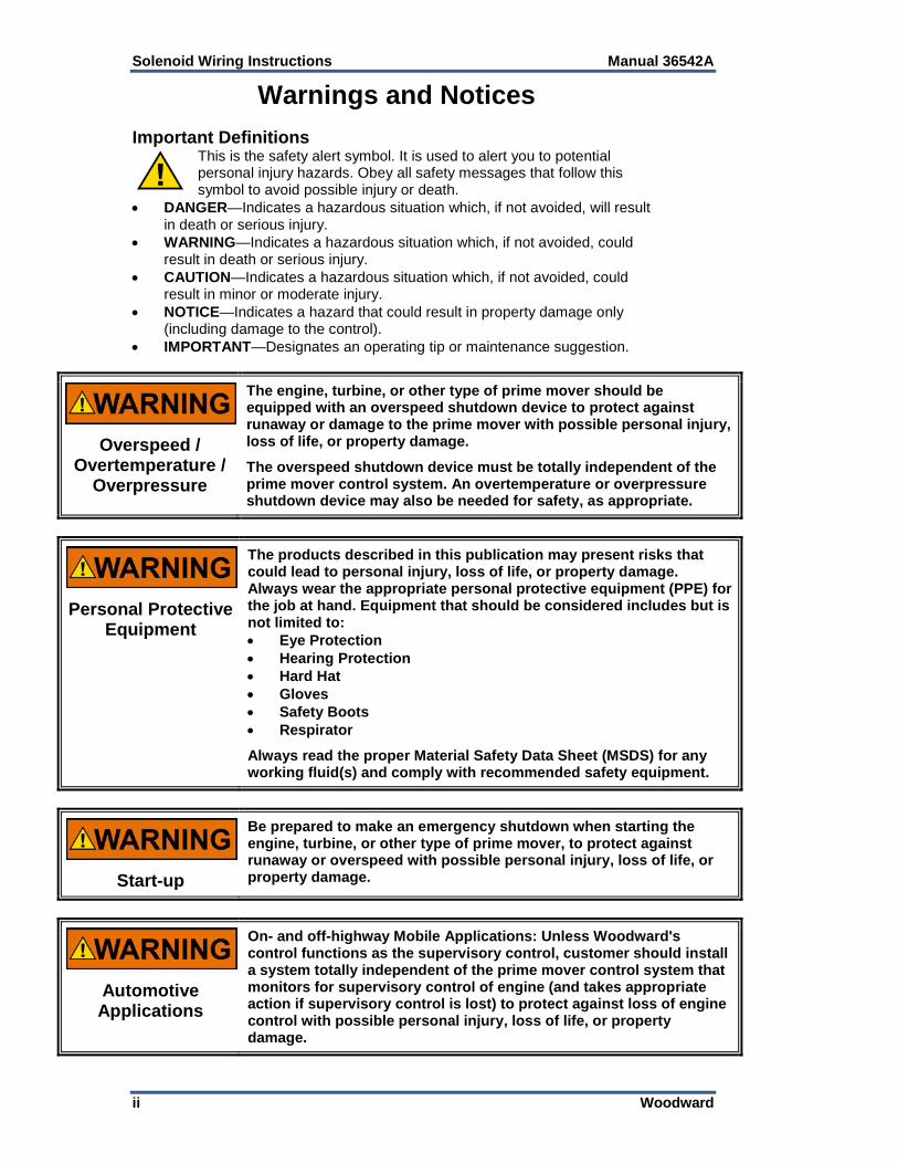
Warnings and Notices Important Definitions
This is the safety alert symbol. It is used to alert you to potential personal injury hazards. Obey all safety messages that follow this symbol to avoid possible injury or death.
• DANGER—Indicates a hazardous situation which, if not avoided, will result in death or serious injury.
• WARNING—Indicates a hazardous situation which, if not avoided, could result in death or serious injury.
• CAUTION—Indicates a hazardous situation which, if not avoided, could result in minor or moderate injury.
• NOTICE—Indicates a hazard that could result in property damage only (including damage to the control).
• IMPORTANT—Designates an operating tip or maintenance suggestion.
Overspeed / Overtemperature /
Overpressure
The engine, turbine, or other type of prime mover should be equipped with an overspeed shutdown device to protect against runaway or damage to the prime mover with possible personal injury, loss of life, or property damage.
The overspeed shutdown device must be totally independent of the prime mover control system. An overtemperature or overpressure shutdown device may also be needed for safety, as appropriate.
Personal Protective Equipment
The products described in this publication may present risks that could lead to personal injury, loss of life, or property damage. Always wear the appropriate personal protective equipment (PPE) for the job at hand. Equipment that should be considered includes but is not limited to: • Eye Protection • Hearing Protection • Hard Hat • Gloves • Safety Boots • Respirator
Always read the proper Material Safety Data Sheet (MSDS) for any working fluid(s) and comply with recommended safety equipment.
Start-up
Be prepared to make an emergency shutdown when starting the engine, turbine, or other type of prime mover, to protect against runaway or overspeed with possible personal injury, loss of life, or property damage.
Automotive Applications
On- and off-highway Mobile Applications: Unless Woodward's control functions as the supervisory control, customer should install a system totally independent of the prime mover control system that monitors for supervisory control of engine (and takes appropriate action if supervisory control is lost) to protect against loss of engine control with possible personal injury, loss of life, or property damage.
Manual 36542A Solenoid Wiring Instructions
Woodward iii
Battery Charging Device
To prevent damage to a control system that uses an alternator or battery-charging device, make sure the charging device is turned off before disconnecting the battery from the system.
Electrostatic Discharge Awareness
Electrostatic Precautions
Electronic controls contain static-sensitive parts. Observe the following precautions to prevent damage to these parts: • Discharge body static before handling the control (with power to
the control turned off, contact a grounded surface and maintain contact while handling the control).
• Avoid all plastic, vinyl, and Styrofoam (except antistatic versions) around printed circuit boards.
• Do not touch the components or conductors on a printed circuit board with your hands or with conductive devices.
To prevent damage to electronic components caused by improper handling, read and observe the precautions in Woodward manual 82715, Guide for Handling and Protection of Electronic Controls, Printed Circuit Boards, and Modules.
Follow these precautions when working with or near the control. 1. Avoid the build-up of static electricity on your body by not wearing clothing
made of synthetic materials. Wear cotton or cotton-blend materials as much as possible because these do not store static electric charges as much as synthetics.
2. Do not remove the printed circuit board (PCB) from the control cabinet unless absolutely necessary. If you must remove the PCB from the control cabinet, follow these precautions:
• Do not touch any part of the PCB except the edges. • Do not touch the electrical conductors, the connectors, or the
components with conductive devices or with your hands. • When replacing a PCB, keep the new PCB in the plastic antistatic
protective bag it comes in until you are ready to install it. Immediately after removing the old PCB from the control cabinet, place it in the antistatic protective bag.

Manual 36542A Solenoid Wiring Instructions
Woodward 1
Chapter 1. General Information
Introduction This manual is a guide to the wiring procedures recommended for internally and externally switched solenoids. For detailed information on Woodward solenoids, refer to Catalog 52132. For product specifications on the Coil CommandersTM and pull coil timer modules mentioned in this manual, refer to Manual 36585. Both documents may be viewed or downloaded from our website at www.woodward.com/publications.
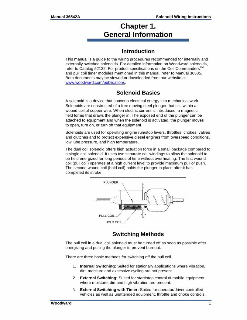
Solenoid Basics A solenoid is a device that converts electrical energy into mechanical work. Solenoids are constructed of a free moving steel plunger that sits within a wound coil of copper wire. When electric current is introduced, a magnetic field forms that draws the plunger in. The exposed end of the plunger can be attached to equipment and when the solenoid is activated, the plunger moves to open, turn on, or turn off that equipment. Solenoids are used for operating engine run/stop levers, throttles, chokes, valves and clutches and to protect expensive diesel engines from overspeed conditions, low lube pressure, and high temperature. The dual coil solenoid offers high actuation force in a small package compared to a single coil solenoid. It uses two separate coil windings to allow the solenoid to be held energized for long periods of time without overheating. The first wound coil (pull coil) operates at a high current level to provide maximum pull or push. The second wound coil (hold coil) holds the plunger in place after it has completed its stroke.
Switching Methods The pull coil in a dual coil solenoid must be turned off as soon as possible after energizing and pulling the plunger to prevent burnout. There are three basic methods for switching off the pull coil.
1. Internal Switching: Suited for stationary applications where vibration, dirt, moisture and excessive cycling are not present.
2. External Switching: Suited for start/stop control of mobile equipment where moisture, dirt and high vibration are present.
3. External Switching with Timer: Suited for operator/driver controlled vehicles as well as unattended equipment, throttle and choke controls.
PLUNGER
PULL COIL
HOLD COIL
Solenoid Wiring Instructions Manual 36542A
2 Woodward
Chapter 2. External Switching
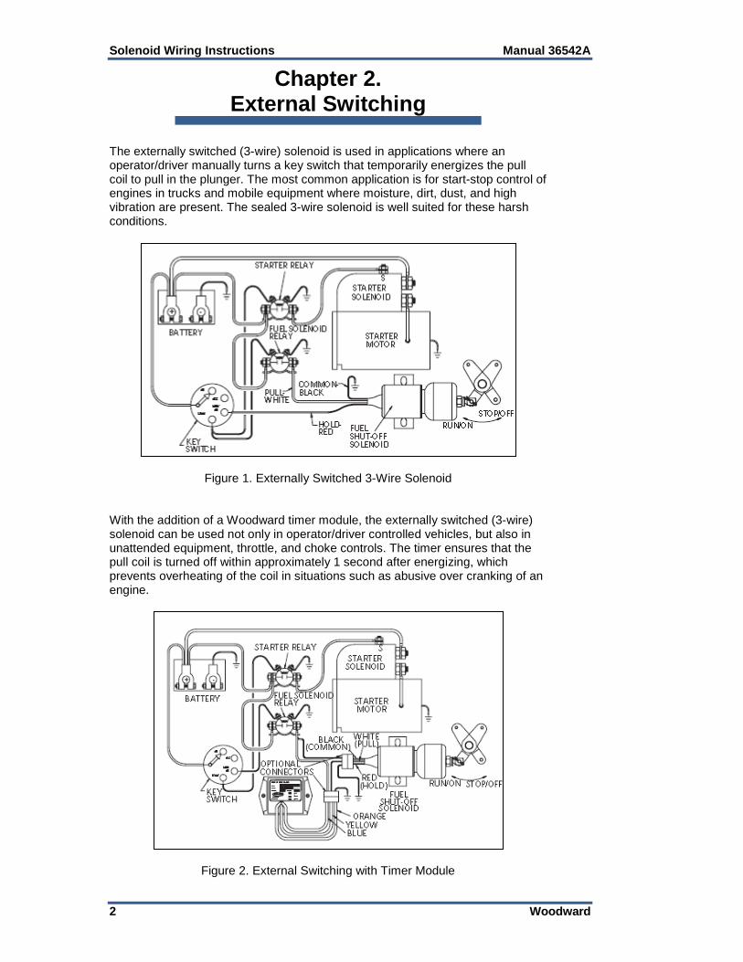
The externally switched (3-wire) solenoid is used in applications where an operator/driver manually turns a key switch that temporarily energizes the pull coil to pull in the plunger. The most common application is for start-stop control of engines in trucks and mobile equipment where moisture, dirt, dust, and high vibration are present. The sealed 3-wire solenoid is well suited for these harsh conditions.
Figure 1. Externally Switched 3-Wire Solenoid With the addition of a Woodward timer module, the externally switched (3-wire) solenoid can be used not only in operator/driver controlled vehicles, but also in unattended equipment, throttle, and choke controls. The timer ensures that the pull coil is turned off within approximately 1 second after energizing, which prevents overheating of the coil in situations such as abusive over cranking of an engine.
Figure 2. External Switching with Timer Module
Manual 36542A Solenoid Wiring Instructions
Woodward 3
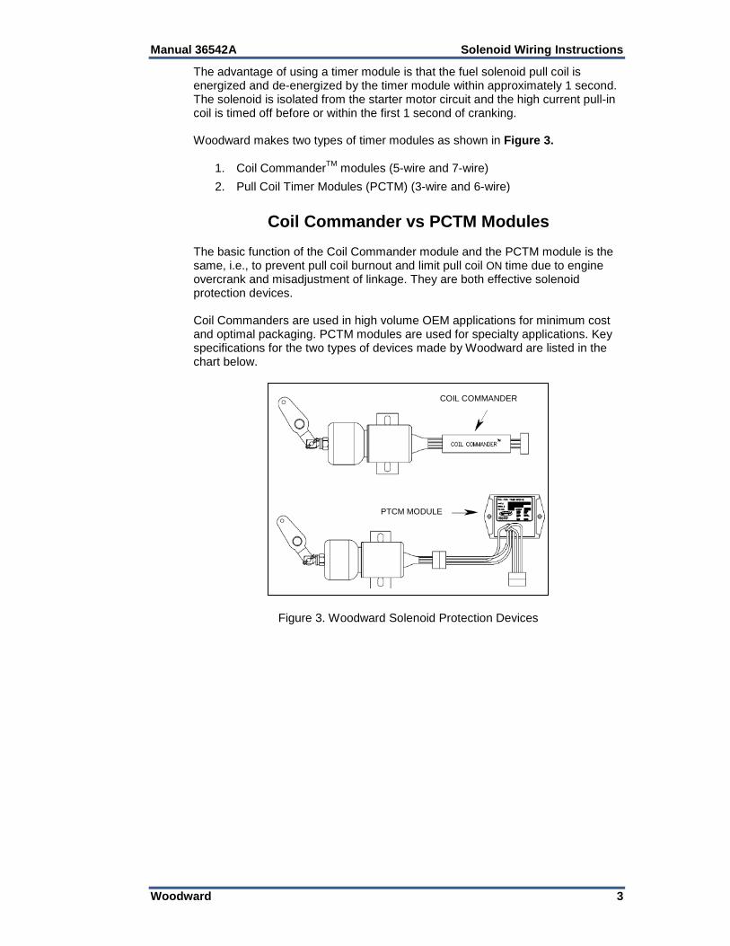
The advantage of using a timer module is that the fuel solenoid pull coil is energized and de-energized by the timer module within approximately 1 second. The solenoid is isolated from the starter motor circuit and the high current pull-in coil is timed off before or within the first 1 second of cranking. Woodward makes two types of timer modules as shown in Figure 3.
1. Coil CommanderTM modules (5-wire and 7-wire) 2. Pull Coil Timer Modules (PCTM) (3-wire and 6-wire)
Coil Commander vs PCTM Modules
The basic function of the Coil Commander module and the PCTM module is the same, i.e., to prevent pull coil burnout and limit pull coil ON time due to engine overcrank and misadjustment of linkage. They are both effective solenoid protection devices. Coil Commanders are used in high volume OEM applications for minimum cost and optimal packaging. PCTM modules are used for specialty applications. Key specifications for the two types of devices made by Woodward are listed in the chart below.
Figure 3. Woodward Solenoid Protection Devices
COIL COMMANDER
PTCM MODULE
Solenoid Wiring Instructions Manual 36542A
4 Woodward
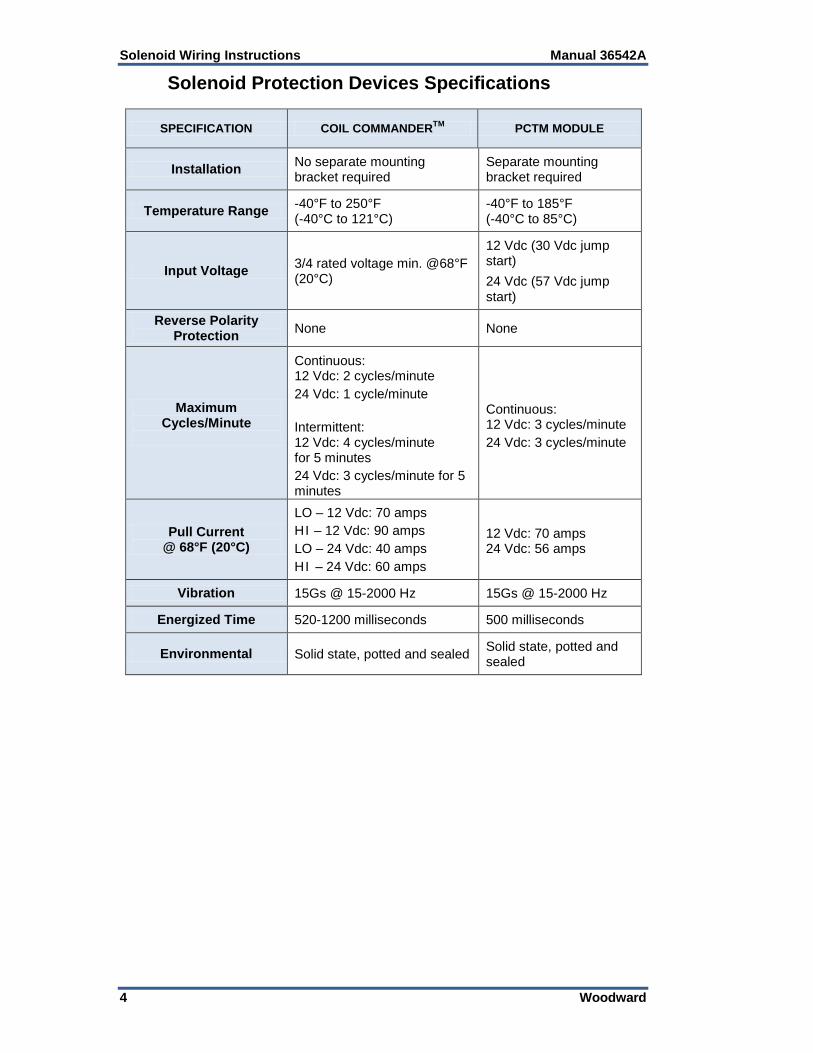
Solenoid Protection Devices Specifications
SPECIFICATION COIL COMMANDERTM PCTM MODULE
Installation No separate mounting bracket required
Separate mounting bracket required
Temperature Range -40°F to 250°F (-40°C to 121°C)
-40°F to 185°F (-40°C to 85°C)
Input Voltage 3/4 rated voltage min. @68°F (20°C)
12 Vdc (30 Vdc jump start) 24 Vdc (57 Vdc jump start)
Reverse Polarity Protection None None
Maximum Cycles/Minute
Continuous: 12 Vdc: 2 cycles/minute 24 Vdc: 1 cycle/minute Intermittent: 12 Vdc: 4 cycles/minute for 5 minutes 24 Vdc: 3 cycles/minute for 5 minutes
Continuous: 12 Vdc: 3 cycles/minute 24 Vdc: 3 cycles/minute
Pull Current @ 68°F (20°C)
LO – 12 Vdc: 70 amps HI – 12 Vdc: 90 amps LO – 24 Vdc: 40 amps HI – 24 Vdc: 60 amps
12 Vdc: 70 amps 24 Vdc: 56 amps
Vibration 15Gs @ 15-2000 Hz 15Gs @ 15-2000 Hz
Energized Time 520-1200 milliseconds 500 milliseconds
Environmental Solid state, potted and sealed Solid state, potted and sealed
Manual 36542A Solenoid Wiring Instructions
Woodward 5
Chapter 3. Internal Switching
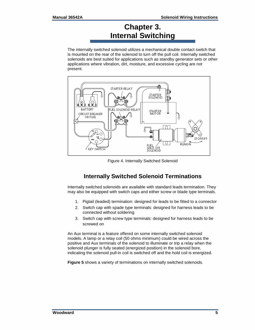
The internally switched solenoid utilizes a mechanical double contact switch that is mounted on the rear of the solenoid to turn off the pull coil. Internally switched solenoids are best suited for applications such as standby generator sets or other applications where vibration, dirt, moisture, and excessive cycling are not present.
Figure 4. Internally Switched Solenoid
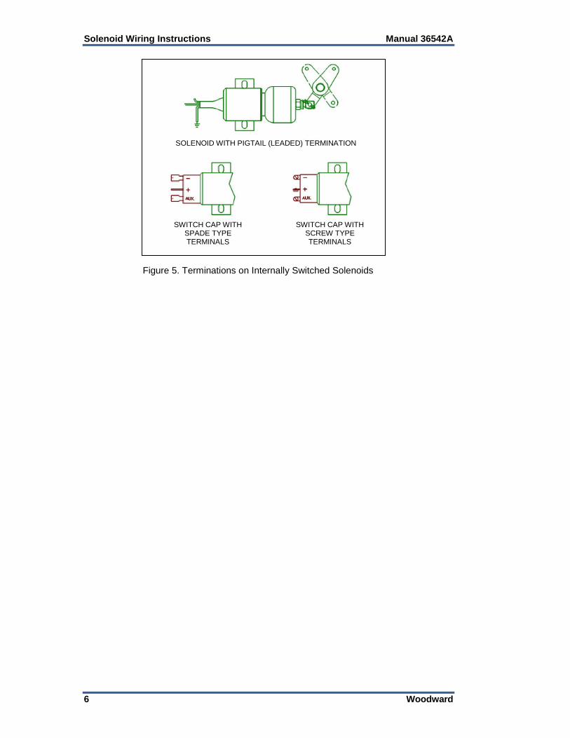
Internally Switched Solenoid Terminations Internally switched solenoids are available with standard leads termination. They may also be equipped with switch caps and either screw or blade type terminals.
1. Pigtail (leaded) termination: designed for leads to be fitted to a connector 2. Switch cap with spade type terminals: designed for harness leads to be
connected without soldering 3. Switch cap with screw type terminals: designed for harness leads to be
screwed on
An Aux terminal is a feature offered on some internally switched solenoid models. A lamp or a relay coil (50 ohms minimum) could be wired across the positive and Aux terminals of the solenoid to illuminate or trip a relay when the solenoid plunger is fully seated (energized position) in the solenoid bore, indicating the solenoid pull-in coil is switched off and the hold coil is energized. Figure 5 shows a variety of terminations on internally switched solenoids.
Solenoid Wiring Instructions Manual 36542A
6 Woodward
Figure 5. Terminations on Internally Switched Solenoids
SOLENOID WITH PIGTAIL (LEADED) TERMINATION
SWITCH CAP WITH SCREW TYPE TERMINALS
SWITCH CAP WITH SPADE TYPE TERMINALS
Manual 36542A Solenoid Wiring Instructions
Woodward 7
Chapter 4. Electric Shut-off (ESO)
Applications
Externally Switched Solenoids
There are five wiring methods for electric shut-off applications, energize to run (ETR):
1. Connection through separate relay 2. Direct connection to starter motor 3. Connection to “S” terminal of starter solenoid (Not Recommended) 4. Connection through Woodward Coil Commander modules 5. Connection through Woodward PCTM modules
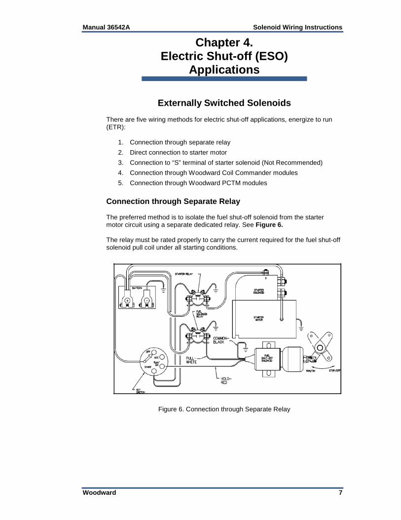
Connection through Separate Relay The preferred method is to isolate the fuel shut-off solenoid from the starter motor circuit using a separate dedicated relay. See Figure 6. The relay must be rated properly to carry the current required for the fuel shut-off solenoid pull coil under all starting conditions.
Figure 6. Connection through Separate Relay
Solenoid Wiring Instructions Manual 36542A
8 Woodward
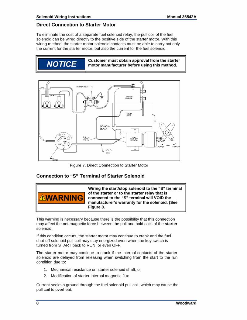
Direct Connection to Starter Motor To eliminate the cost of a separate fuel solenoid relay, the pull coil of the fuel solenoid can be wired directly to the positive side of the starter motor. With this wiring method, the starter motor solenoid contacts must be able to carry not only the current for the starter motor, but also the current for the fuel solenoid.
Customer must obtain approval from the starter motor manufacturer before using this method.
Figure 7. Direct Connection to Starter Motor
Connection to “S” Terminal of Starter Solenoid
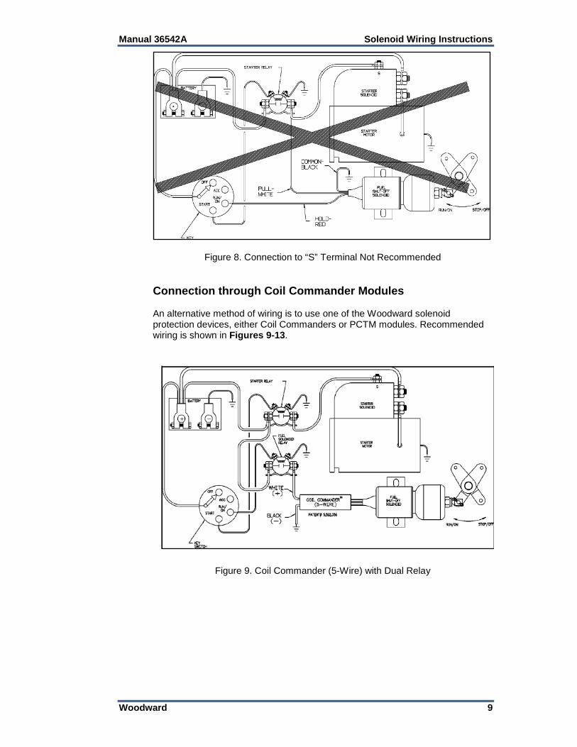
Wiring the start/stop solenoid to the “S” terminal of the starter or to the starter relay that is connected to the “S” terminal will VOID the manufacturer’s warranty for the solenoid. (See Figure 8.
This warning is necessary because there is the possibility that this connection may affect the net magnetic force between the pull and hold coils of the starter solenoid. If this condition occurs, the starter motor may continue to crank and the fuel shut-off solenoid pull coil may stay energized even when the key switch is turned from START back to RUN, or even OFF. The starter motor may continue to crank if the internal contacts of the starter solenoid are delayed from releasing when switching from the start to the run condition due to:
1. Mechanical resistance on starter solenoid shaft, or 2. Modification of starter internal magnetic flux
Current seeks a ground through the fuel solenoid pull coil, which may cause the pull coil to overheat.
Manual 36542A Solenoid Wiring Instructions
Woodward 9
Figure 8. Connection to “S” Terminal Not Recommended Connection through Coil Commander Modules An alternative method of wiring is to use one of the Woodward solenoid protection devices, either Coil Commanders or PCTM modules. Recommended wiring is shown in Figures 9-13.
Figure 9. Coil Commander (5-Wire) with Dual Relay
Solenoid Wiring Instructions Manual 36542A
10 Woodward
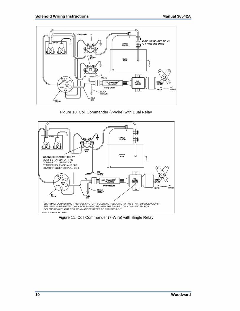
Figure 10. Coil Commander (7-Wire) with Dual Relay
Figure 11. Coil Commander (7-Wire) with Single Relay
WARNING: STARTER RELAY MUST BE RATED FOR THE COMBINED CURRENT OF STARTER SOLENOID AND FUEL SHUTOFF SOLENOID PULL COIL
WARNING: CONNECTING THE FUEL SHUTOFF SOLENOID PULL COIL TO THE STARTER SOLENOID “S” TERMINAL IS PERMTTED ONLY FOR SOLENOIDS WITH THE 7-WIRE COIL COMMANDER. FOR SOLENOIDS WITHOUT COIL COMMANDER REFER TO FIGURES 6 & 7.
Manual 36542A Solenoid Wiring Instructions
Woodward 11
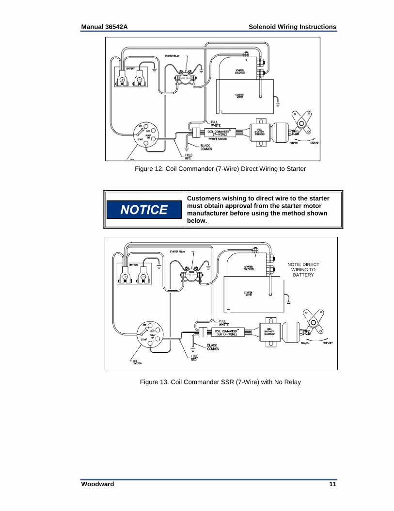
Figure 12. Coil Commander (7-Wire) Direct Wiring to Starter
Customers wishing to direct wire to the starter must obtain approval from the starter motor manufacturer before using the method shown below.
Figure 13. Coil Commander SSR (7-Wire) with No Relay
NOTE: DIRECT WIRING TO BATTERY
Solenoid Wiring Instructions Manual 36542A
12 Woodward
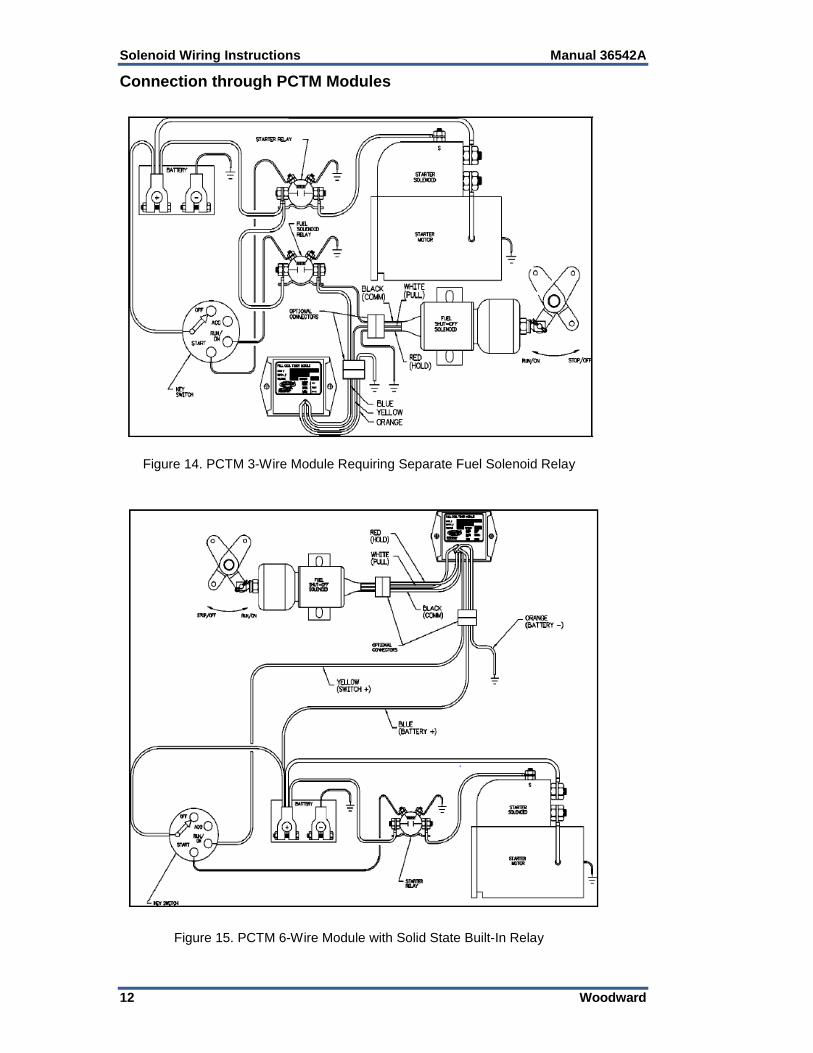
Connection through PCTM Modules
Figure 14. PCTM 3-Wire Module Requiring Separate Fuel Solenoid Relay
Figure 15. PCTM 6-Wire Module with Solid State Built-In Relay
Manual 36542A Solenoid Wiring Instructions
Woodward 13
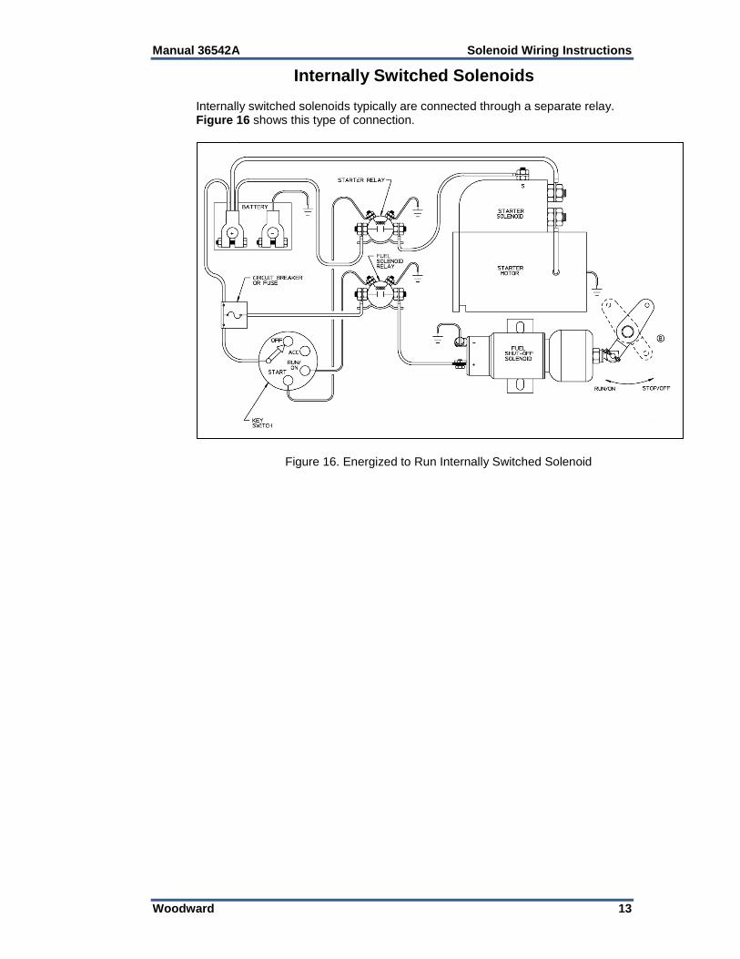
Internally Switched Solenoids
Internally switched solenoids typically are connected through a separate relay. Figure 16 shows this type of connection.
Figure 16. Energized to Run Internally Switched Solenoid
Solenoid Wiring Instructions Manual 36542A
14 Woodward
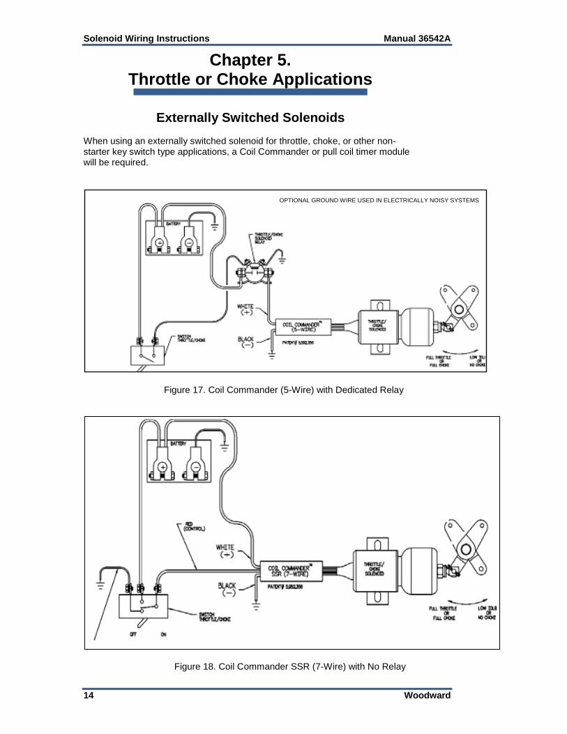
Chapter 5. Throttle or Choke Applications
Externally Switched Solenoids When using an externally switched solenoid for throttle, choke, or other non-starter key switch type applications, a Coil Commander or pull coil timer module will be required.
Figure 17. Coil Commander (5-Wire) with Dedicated Relay
Figure 18. Coil Commander SSR (7-Wire) with No Relay
OPTIONAL GROUND WIRE USED IN ELECTRICALLY NOISY SYSTEMS
Manual 36542A Solenoid Wiring Instructions
Woodward 15
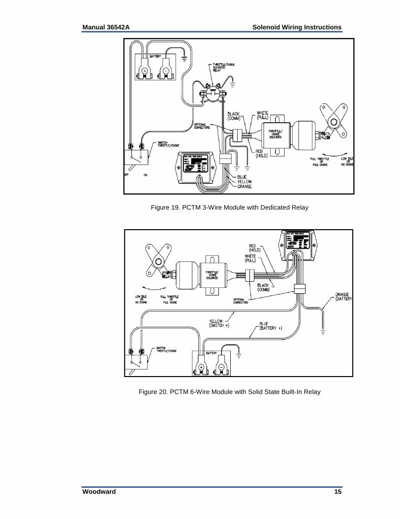
Figure 19. PCTM 3-Wire Module with Dedicated Relay
Figure 20. PCTM 6-Wire Module with Solid State Built-In Relay
Solenoid Wiring Instructions Manual 36542A
16 Woodward
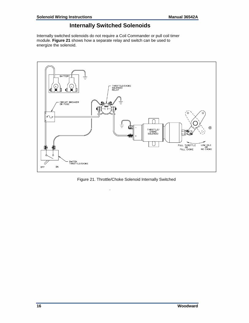
Internally Switched Solenoids
Internally switched solenoids do not require a Coil Commander or pull coil timer module. Figure 21 shows how a separate relay and switch can be used to energize the solenoid.
Figure 21. Throttle/Choke Solenoid Internally Switched .
Manual 36542A Solenoid Wiring Instructions
Woodward 17
Chapter 6. Product Support and Service Options
Product Support Options If you are experiencing problems with the installation, or unsatisfactory performance of a Woodward product, the following options are available: 1. Consult the troubleshooting guide in the manual. 2. Contact the OE Manufacturer or Packager of your system. 3. Contact the Woodward Business Partner serving your area. 4. Contact Woodward technical assistance via email
([email protected]) with detailed information on the product, application, and symptoms. Your email will be forwarded to an appropriate expert on the product and application to respond by telephone or return email.
5. If the issue cannot be resolved, you can select a further course of action to pursue based on the available services listed in this chapter.
OEM or Packager Support: Many Woodward controls and control devices are installed into the equipment system and programmed by an Original Equipment Manufacturer (OEM) or Equipment Packager at their factory. In some cases, the programming is password-protected by the OEM or packager, and they are the best source for product service and support. Warranty service for Woodward products shipped with an equipment system should also be handled through the OEM or Packager. Please review your equipment system documentation for details. Woodward Business Partner Support: Woodward works with and supports a global network of independent business partners whose mission is to serve the users of Woodward controls, as described here:
• A Full-Service Distributor has the primary responsibility for sales, service, system integration solutions, technical desk support, and aftermarket marketing of standard Woodward products within a specific geographic area and market segment.
• An Authorized Independent Service Facility (AISF) provides authorized service that includes repairs, repair parts, and warranty service on Woodward's behalf. Service (not new unit sales) is an AISF's primary mission.
• A Recognized Engine Retrofitter (RER) is an independent company that does retrofits and upgrades on reciprocating gas engines and dual-fuel conversions, and can provide the full line of Woodward systems and components for the retrofits and overhauls, emission compliance upgrades, long term service contracts, emergency repairs, etc.
A current list of Woodward Business Partners is available at www.woodward.com/directory.
Product Service Options Depending on the type of product, the following options for servicing Woodward products may be available through your local Full-Service Distributor or the OEM or Packager of the equipment system. • Replacement/Exchange (24-hour service) • Flat Rate Repair • Flat Rate Remanufacture
Solenoid Wiring Instructions Manual 36542A
18 Woodward
Replacement/Exchange: Replacement/Exchange is a premium program designed for the user who is in need of immediate service. It allows you to request and receive a like-new replacement unit in minimum time (usually within 24 hours of the request), providing a suitable unit is available at the time of the request, thereby minimizing costly downtime. This option allows you to call your Full-Service Distributor in the event of an unexpected outage, or in advance of a scheduled outage, to request a replacement control unit. If the unit is available at the time of the call, it can usually be shipped out within 24 hours. You replace your field control unit with the like-new replacement and return the field unit to the Full-Service Distributor. Flat Rate Repair: Flat Rate Repair is available for many of the standard mechanical products and some of the electronic products in the field. This program offers you repair service for your products with the advantage of knowing in advance what the cost will be. Flat Rate Remanufacture: Flat Rate Remanufacture is very similar to the Flat Rate Repair option, with the exception that the unit will be returned to you in “like-new” condition. This option is applicable to mechanical products only.
Returning Equipment for Repair If a control (or any part of an electronic control) is to be returned for repair, please contact your Full-Service Distributor in advance to obtain Return Authorization and shipping instructions. When shipping the item(s), attach a tag with the following information: • return number; • name and location where the control is installed; • name and phone number of contact person; • complete Woodward part number(s) and serial number(s); • description of the problem; • instructions describing the desired type of repair. Packing a Control Use the following materials when returning a complete control: • protective caps on any connectors; • antistatic protective bags on all electronic modules; • packing materials that will not damage the surface of the unit; • at least 100 mm (4 inches) of tightly packed, industry-approved packing
material; • a packing carton with double walls; • a strong tape around the outside of the carton for increased strength.
To prevent damage to electronic components caused by improper handling, read and observe the precautions in Woodward manual 82715, Guide for Handling and Protection of Electronic Controls, Printed Circuit Boards, and Modules.
Replacement Parts When ordering replacement parts for controls, include the following information: • the part number(s) (XXXX-XXXX) that is on the enclosure nameplate; • the unit serial number, which is also on the nameplate.
Manual 36542A Solenoid Wiring Instructions
Woodward 19
Engineering Services Woodward’s Full-Service Distributors offer various Engineering Services for our products. For these services, you can contact the Distributor by telephone or by email. • Technical Support • Product Training • Field Service Technical Support is available from your equipment system supplier, your local Full-Service Distributor, or from many of Woodward’s worldwide locations, depending upon the product and application. This service can assist you with technical questions or problem solving during the normal business hours of the Woodward location you contact. Product Training is available as standard classes at many Distributor locations. Customized classes are also available, which can be tailored to your needs and held at one of our Distributor locations or at your site. This training, conducted by experienced personnel, will assure that you will be able to maintain system reliability and availability. Field Service engineering on-site support is available, depending on the product and location, from one of our Full-Service Distributors. The field engineers are experienced both on Woodward products as well as on much of the non-Woodward equipment with which our products interface. For information on these services, please contact one of the Full-Service Distributors listed at www.woodward.com/directory.
Contacting Woodward’s Support Organization For the name of your nearest Woodward Full-Service Distributor or service facility, please consult our worldwide directory published at www.woodward.com/directory. You can also contact the Woodward Customer Service Department at one of the following Woodward facilities to obtain the address and phone number of the nearest facility at which you can obtain information and service.
Products Used In Electrical Power Systems
Facility ---------------- Phone Number Brazil ------------- +55 (19) 3708 4800 China ----------- +86 (512) 6762 6727 Germany: Kempen ---- +49 (0) 21 52 14 51 Stuttgart -- +49 (711) 78954-510 India --------------- +91 (129) 4097100 Japan -------------- +81 (43) 213-2191 Korea -------------- +82 (51) 636-7080 Poland --------------- +48 12 295 13 00 United States ---- +1 (970) 482-5811
Products Used In Engine Systems
Facility ---------------- Phone Number Brazil ------------- +55 (19) 3708 4800 China ----------- +86 (512) 6762 6727 Germany ------- +49 (711) 78954-510 India --------------- +91 (129) 4097100 Japan -------------- +81 (43) 213-2191 Korea -------------- +82 (51) 636-7080 The Netherlands - +31 (23) 5661111 United States ---- +1 (970) 482-5811
Products Used In Industrial Turbomachinery
Systems Facility ---------------- Phone Number Brazil ------------- +55 (19) 3708 4800 China ----------- +86 (512) 6762 6727 India --------------- +91 (129) 4097100 Japan -------------- +81 (43) 213-2191 Korea -------------- +82 (51) 636-7080 The Netherlands - +31 (23) 5661111 Poland --------------- +48 12 295 13 00 United States ---- +1 (970) 482-5811
For the most current product support and contact information, please visit our website directory at www.woodward.com/directory.
Solenoid Wiring Instructions Manual 36542A
20 Woodward
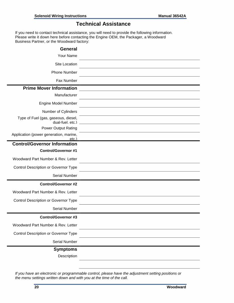
Technical Assistance
If you need to contact technical assistance, you will need to provide the following information. Please write it down here before contacting the Engine OEM, the Packager, a Woodward Business Partner, or the Woodward factory:
General
Your Name
Site Location
Phone Number
Fax Number
Prime Mover Information
Manufacturer
Engine Model Number
Number of Cylinders
Type of Fuel (gas, gaseous, diesel, dual-fuel, etc.)
Power Output Rating
Application (power generation, marine, etc.)
Control/Governor Information
Control/Governor #1
Woodward Part Number & Rev. Letter
Control Description or Governor Type
Serial Number
Control/Governor #2
Woodward Part Number & Rev. Letter
Control Description or Governor Type
Serial Number
Control/Governor #3
Woodward Part Number & Rev. Letter
Control Description or Governor Type
Serial Number
Symptoms
Description
If you have an electronic or programmable control, please have the adjustment setting positions or the menu settings written down and with you at the time of the call.

We appreciate your comments about the content of our publications.
Send comments to: [email protected]
Please reference publication 36542A.
PO Box 1519, Fort Collins CO 80522-1519, USA 1000 East Drake Road, Fort Collins CO 80525, USA Phone +1 (970) 482-5811 Fax +1 (970) 498-3058
Email and Website—www.woodward.com
Woodward has company-owned plants, subsidiaries, and branches, as well as authorized distributors and other authorized service and sales facilities throughout the world.
Complete address / phone / fax / email information for all locations is available on our website.