interferometers history
TRANSCRIPT
1
INTERFEROMETERSHISTORY
SOLO HERMELINUpdated: 6.01.11
4.01.15http://www.solohermelin.com
2
InterferenceSOLO
Table of Content
Introduction
Haidinger Fringes
Fizeau Experiment
Jamin’s Interferometer
Fizeau Experiment in Moving Media and Fizeau Interferometer
Foucault Experiment
Michelson Interferometer
Mach-Zehnder Interferometer
Rayleigh’s Interferometer
Sirks-Pringsheim Interferometer
Fabry – Perot Interferometer
Sagnac Effect
Twyman-Green Interferometer
Michelson’s Experiments
Dyson’s Interferometer
Hanbury-Brown and Twiss InterferometerGires-Tournois Etalon
3
InterferenceSOLO
Table of Content (continue – 1)
Interference of Two Monochromatic Waves
Two Basic Classes of Interferometers
Fresnel’s Double Mirror (1819*)
Fresnel’s Double Prism
Lloyd’s Mirror Interferometer
Young’s ExperimentDivision of Wavefront
Optical Reflected Path Length Difference: Parallel Interfaces
Amplitude Split InterferometersStokes Treatment of Reflection and Refraction
Optical Transmitted Path Length Difference: Parallel Interfaces
Haidinger Interference Fringes
Interference of Many Monochromatic Waves
Gas Refrectometer
References
4
InterferenceSOLO
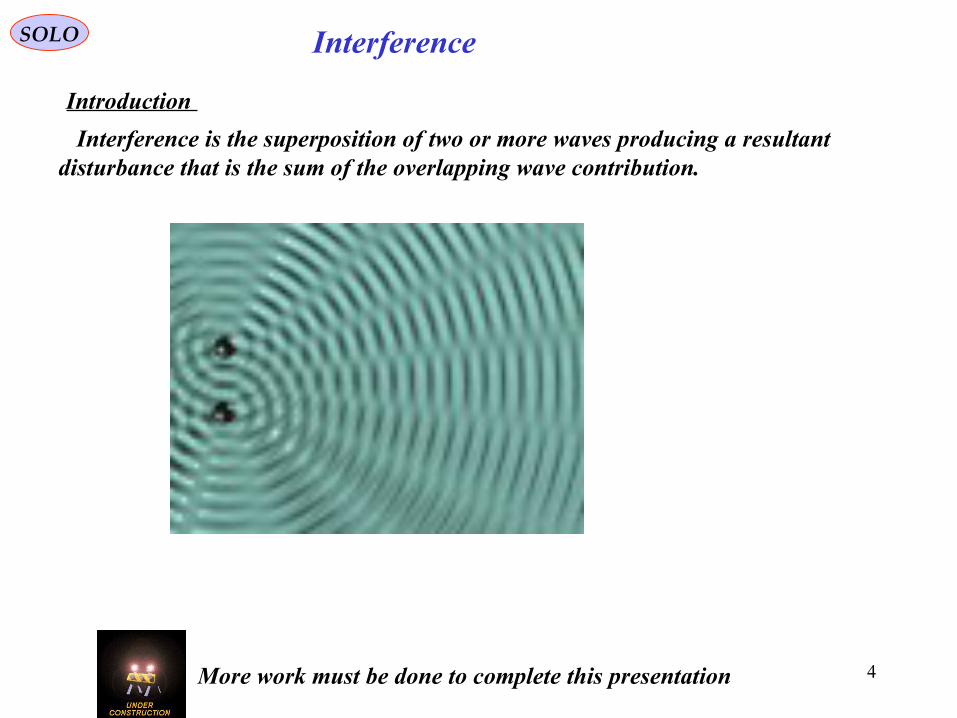
Introduction
Interference is the superposition of two or more waves producing a resultant disturbance that is the sum of the overlapping wave contribution.
More work must be done to complete this presentation
5
SOLO Diffraction
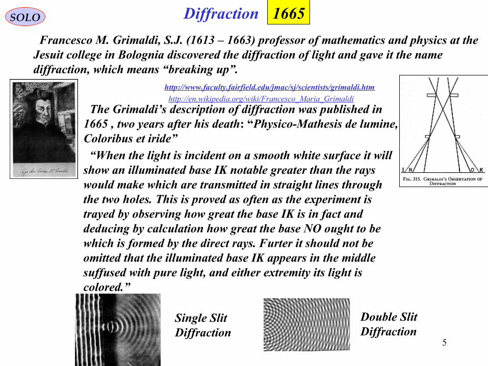
The Grimaldi’s description of diffraction was published in1665 , two years after his death: “Physico-Mathesis de lumine,Coloribus et iride”
Francesco M. Grimaldi, S.J. (1613 – 1663) professor of mathematics and physics at theJesuit college in Bolognia discovered the diffraction of light and gave it the namediffraction, which means “breaking up”.
http://www.faculty.fairfield.edu/jmac/sj/scientists/grimaldi.htm
“When the light is incident on a smooth white surface it will show an illuminated base IK notable greater than the rays would make which are transmitted in straight lines through the two holes. This is proved as often as the experiment is trayed by observing how great the base IK is in fact and deducing by calculation how great the base NO ought to bewhich is formed by the direct rays. Furter it should not beomitted that the illuminated base IK appears in the middlesuffused with pure light, and either extremity its light iscolored.”
Single SlitDiffraction
Double SlitDiffraction
http://en.wikipedia.org/wiki/Francesco_Maria_Grimaldi
1665
6
SOLO Microscope
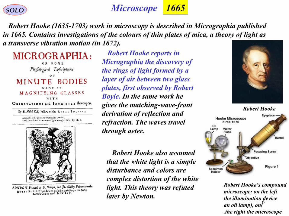
Robert Hooke (1635-1703) work in microscopy is described in Micrographia published in 1665. Contains investigations of the colours of thin plates of mica, a theory of light as a transverse vibration motion (in 1672).
1665
Robert Hooke (1635-1703)
Robert Hooke’s compoundmicroscope: on the leftthe illumination device
(an oil lamp), onthe right the microscope.
Robert Hooke reports in Micrographia the discovery of the rings of light formed by a layer of air between two glass plates, first observed by Robert Boyle. In the same work he gives the matching-wave-frontderivation of reflection and refraction. The waves travel through aeter.
Robert Hooke also assumed that the white light is a simple disturbance and colors are complex distortion of the white light. This theory was refuted later by Newton.
7
Optics SOLO
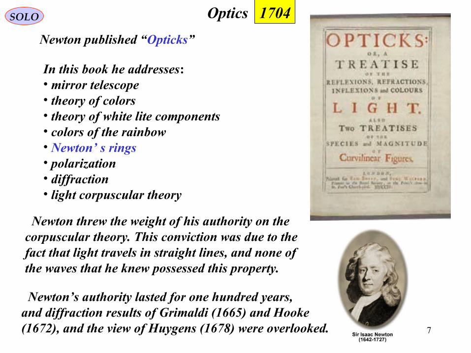
Newton published “Opticks”
1704
In this book he addresses:• mirror telescope• theory of colors• theory of white lite components• colors of the rainbow • Newton’ s rings • polarization• diffraction • light corpuscular theory
Newton threw the weight of his authority on thecorpuscular theory. This conviction was due to thefact that light travels in straight lines, and none of the waves that he knew possessed this property.
Newton’s authority lasted for one hundred years,and diffraction results of Grimaldi (1665) and Hooke (1672), and the view of Huygens (1678) were overlooked.
8
InterferenceSOLO
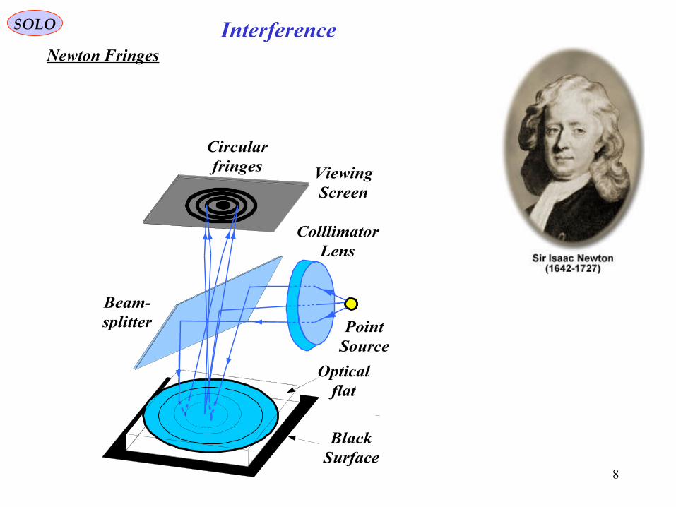
Newton Fringes
ColllimatorLens
Beam-splitter Point
Source
ViewingScreen
Opticalflat
Circularfringes
BlackSurface
9
OpticsSOLO
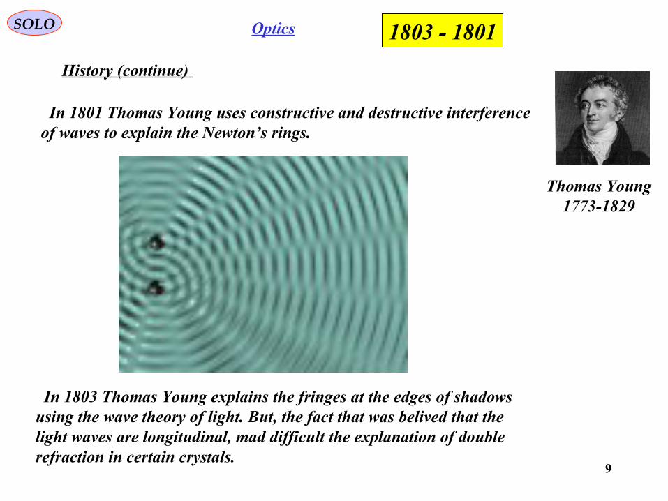
History (continue)
In 1801 Thomas Young uses constructive and destructive interference of waves to explain the Newton’s rings.
Thomas Young1773-1829
1801 - 1803
In 1803 Thomas Young explains the fringes at the edges of shadows using the wave theory of light. But, the fact that was belived that the light waves are longitudinal, mad difficult the explanation of double refraction in certain crystals.
10
POLARIZATIONSOLO
History
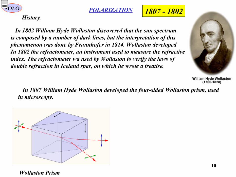
In 1802 William Hyde Wollaston discovered that the sun spectrumis composed by a number of dark lines, but the interpretation of thisphenomenon was done by Fraunhofer in 1814. Wollaston developed In 1802 the refractometer, an instrument used to measure the refractiveindex. The refractometer wa used by Wollaston to verify the laws of double refraction in Iceland spar, on which he wrote a treatise.
Wollaston Prism
In 1807 William Hyde Wollaston developed the four-sided Wollaston prism, usedin microscopy.
1802 - 1807
11
SOLO
History
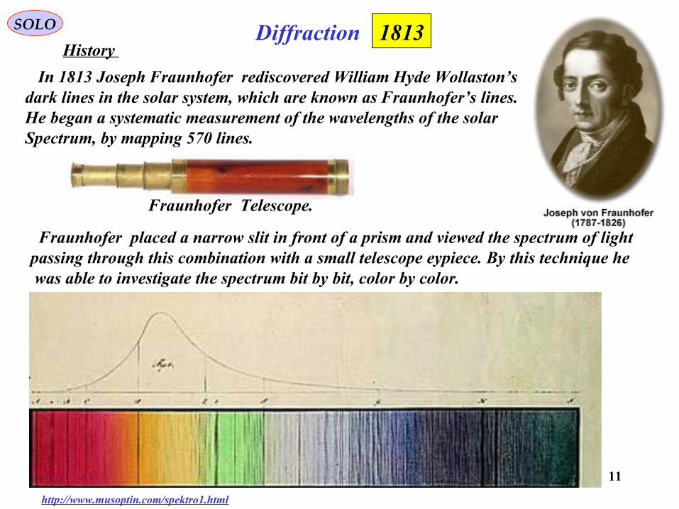
In 1813 Joseph Fraunhofer rediscovered William Hyde Wollaston’s dark lines in the solar system, which are known as Fraunhofer’s lines.He began a systematic measurement of the wavelengths of the solar Spectrum, by mapping 570 lines.
Diffraction
http://www.musoptin.com/spektro1.html
1813
Fraunhofer Telescope.
Fraunhofer placed a narrow slit in front of a prism and viewed the spectrum of lightpassing through this combination with a small telescope eypiece. By this technique he was able to investigate the spectrum bit by bit, color by color.
12
SOLO
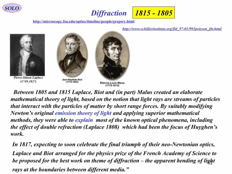
Between 1805 and 1815 Laplace, Biot and (in part) Malus created an elaborate mathematical theory of light, based on the notion that light rays are streams of particles that interact with the particles of matter by short range forces. By suitably modifying Newton’s original emission theory of light and applying superior mathematical methods, they were able to explain most of the known optical phenomena, including the effect of double refraction (Laplace 1808) which had been the focus of Huyghen’s work.
Diffractionhttp://microscopy.fsu.edu/optics/timeline/people/gregory.html
http://www.schillerinstitute.org/fid_97-01/993poisson_jbt.html
Pierre-Simon Laplace(1749-1827)
1805 - 1815
In 1817, expecting to soon celebrate the final triumph of their neo-Newtonian optics,
Laplace and Biot arranged for the physics prize of the French Academy of Science to be proposed for the best work on theme of diffraction – the apparent bending of light
rays at the boundaries between different media.”
13
SOLO
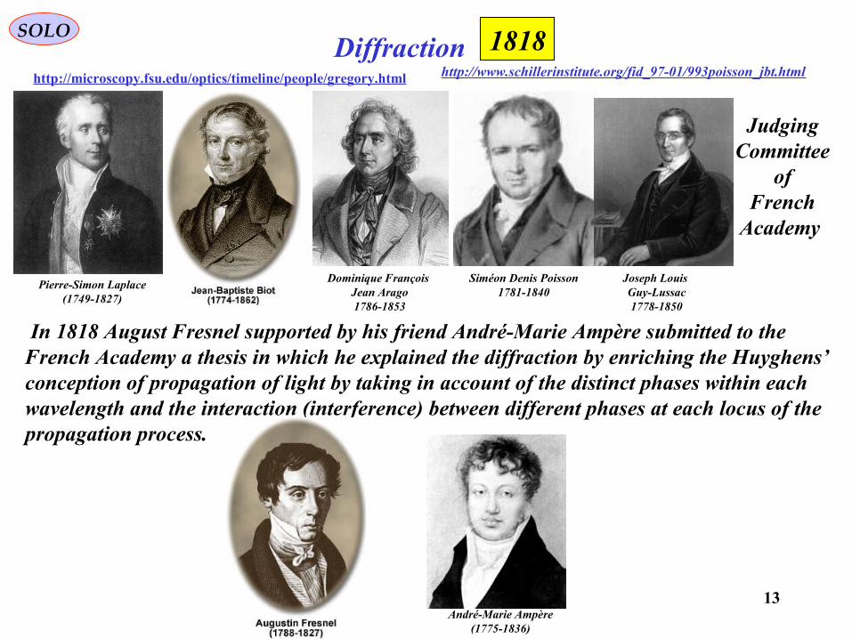
In 1818 August Fresnel supported by his friend André-Marie Ampère submitted to the French Academy a thesis in which he explained the diffraction by enriching the Huyghens’ conception of propagation of light by taking in account of the distinct phases within each wavelength and the interaction (interference) between different phases at each locus of the propagation process.
Diffractionhttp://microscopy.fsu.edu/optics/timeline/people/gregory.html http://www.schillerinstitute.org/fid_97-01/993poisson_jbt.html
André-Marie Ampère(1775-1836)
Dominique François Jean Arago1786-1853
Siméon Denis Poisson1781-1840
Pierre-Simon Laplace(1749-1827)
Joseph Louis Guy-Lussac1778-1850
JudgingCommittee
ofFrench
Academy
1818
14
SOLODiffraction
http://microscopy.fsu.edu/optics/timeline/people/gregory.html http://www.schillerinstitute.org/fid_97-01/993poisson_jbt.html
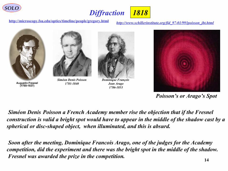
Dominique François Jean Arago1786-1853
Siméon Denis Poisson a French Academy member rise the objection that if the Fresnel construction is valid a bright spot would have to appear in the middle of the shadow cast by a spherical or disc-shaped object, when illuminated, and this is absurd.
Soon after the meeting, Dominique Francois Arago, one of the judges for the Academy competition, did the experiment and there was the bright spot in the middle of the shadow. Fresnel was awarded the prize in the competition.
Siméon Denis Poisson1781-1840
Poisson’s or Arago’s Spot
1818
15
POLARIZATION
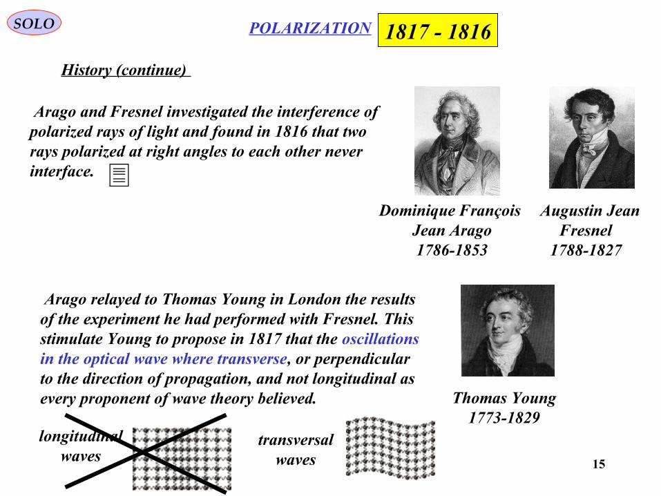
Arago and Fresnel investigated the interference of polarized rays of light and found in 1816 that tworays polarized at right angles to each other never interface.
SOLO
History (continue)
Dominique François Jean Arago1786-1853
Augustin Jean Fresnel
1788-1827
Arago relayed to Thomas Young in London the resultsof the experiment he had performed with Fresnel. This stimulate Young to propose in 1817 that the oscillationsin the optical wave where transverse, or perpendicular to the direction of propagation, and not longitudinal as every proponent of wave theory believed. Thomas Young
1773-1829
1816 - 1817
longitudinalwaves
transversalwaves
16
Diffraction SOLO
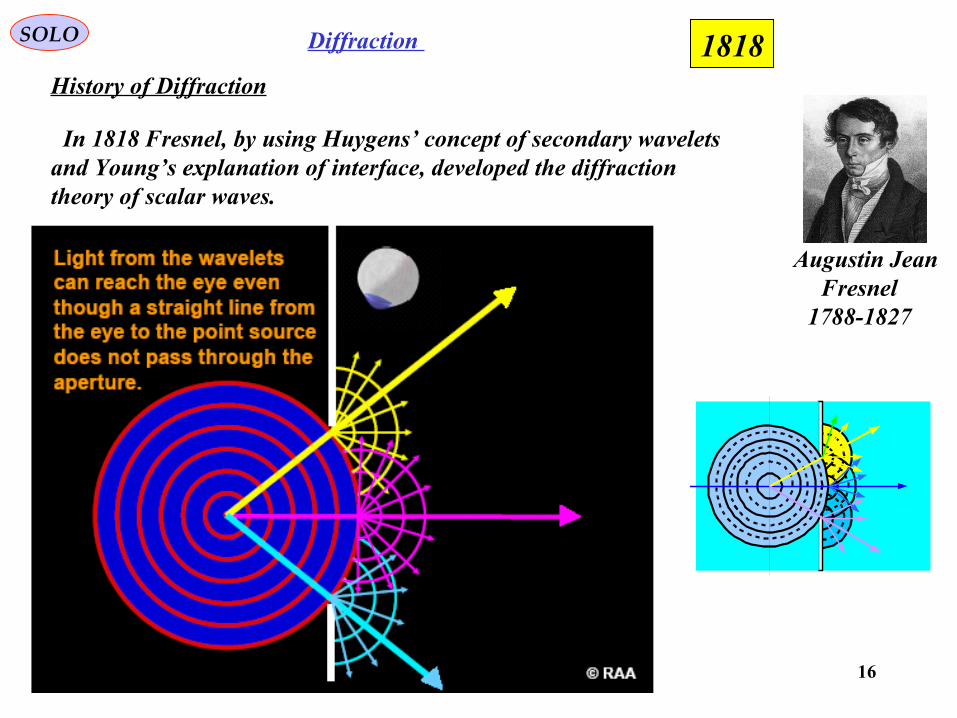
History of Diffraction
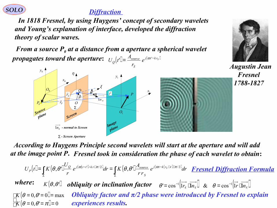
Augustin Jean Fresnel
1788-1827
In 1818 Fresnel, by using Huygens’ concept of secondary wavelets and Young’s explanation of interface, developed the diffraction theory of scalar waves.
1818
17
Diffraction SOLO
Augustin Jean Fresnel
1788-1827
In 1818 Fresnel, by using Huygens’ concept of secondary wavelets and Young’s explanation of interface, developed the diffraction theory of scalar waves.
P
0P
Q1x
0x1y
0y η
ξ
Fr
Sr
ρr
O
'θ θ
Screen
Image
plane
Source
plane
0O
1O
Sn1
Σ
Σ - Screen Aperture
Sn1 - normal to Screen
From a source P0 at a distance from a aperture a spherical wavelet propagates toward the aperture: ( ) ( )Srktj
S
sourceQ e
r
AtU −= '' ω
According to Huygens Principle second wavelets will start at the aperture and will add at the image point P.
( ) ( ) ( )( ) ( ) ( )( )∫∫Σ
++−
Σ
+−− == drerr
AKdre
r
UKtU rrktj
S
sourcerkttjQP
S 2/2/' ',', πωπω θθθθ
where: ( )',θθK obliquity or inclination factor ( ) ( )SSS nrnr 11cos&11cos' 11 ⋅=⋅= −− θθ
( )( )
======0',0
max0',0
πθθθθ
K
K Obliquity factor and π/2 phase were introduced by Fresnel to explain experiences results.
Fresnel Diffraction Formula
Fresnel took in consideration the phase of each wavelet to obtain:
18
SOLO
History
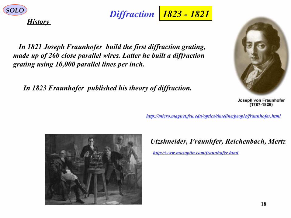
In 1821 Joseph Fraunhofer build the first diffraction grating, made up of 260 close parallel wires. Latter he built a diffractiongrating using 10,000 parallel lines per inch.
Diffraction
Utzshneider, Fraunhfer, Reichenbach, Mertz
http://www.musoptin.com/fraunhofer.html
1821 - 1823
In 1823 Fraunhofer published his theory of diffraction.
http://micro.magnet.fsu.edu/optics/timeline/people/fraunhofer.html
19
SOLO ELECTROMAGNETICS
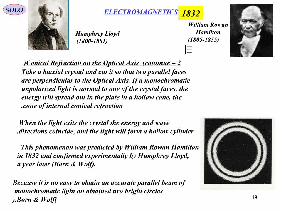
Conical Refraction on the Optical Axis (continue – 2) Take a biaxial crystal and cut it so that two parallel faces
are perpendicular to the Optical Axis. If a monochromaticunpolarized light is normal to one of the crystal faces, theenergy will spread out in the plate in a hollow cone, thecone of internal conical refraction.
When the light exits the crystal the energy and wave directions coincide, and the light will form a hollow cylinder.
This phenomenon was predicted by William Rowan Hamiltonin 1832 and confirmed experimentally by Humphrey Lloyd, a year later (Born & Wolf).
Because it is no easy to obtain an accurate parallel beam ofmonochromatic light on obtained two bright circles
(Born & Wolf).
1832William Rowan
Hamilton(1805-1855)
Humphrey Lloyd(1800-1881)
20
SOLO
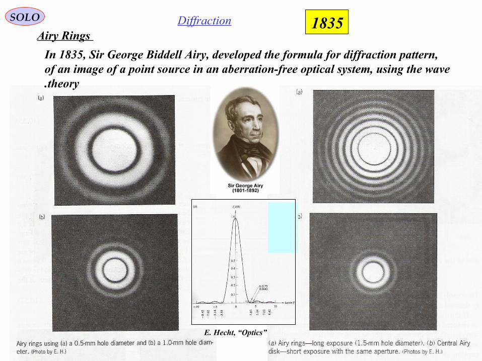
Airy Rings
In 1835, Sir George Biddell Airy, developed the formula for diffraction pattern, of an image of a point source in an aberration-free optical system, using the wave theory.
E. Hecht, “Optics”
Diffraction 1835
21
InterferenceSOLO
Haidinger Fringes1846
Wilhelm Karl, Ritter von Haidinger
1795 - 1871
Lens
Beam-splitter
ExtendedSources
ViewingScreen
Dielectricfilm
Blackbackground
Circularfringes
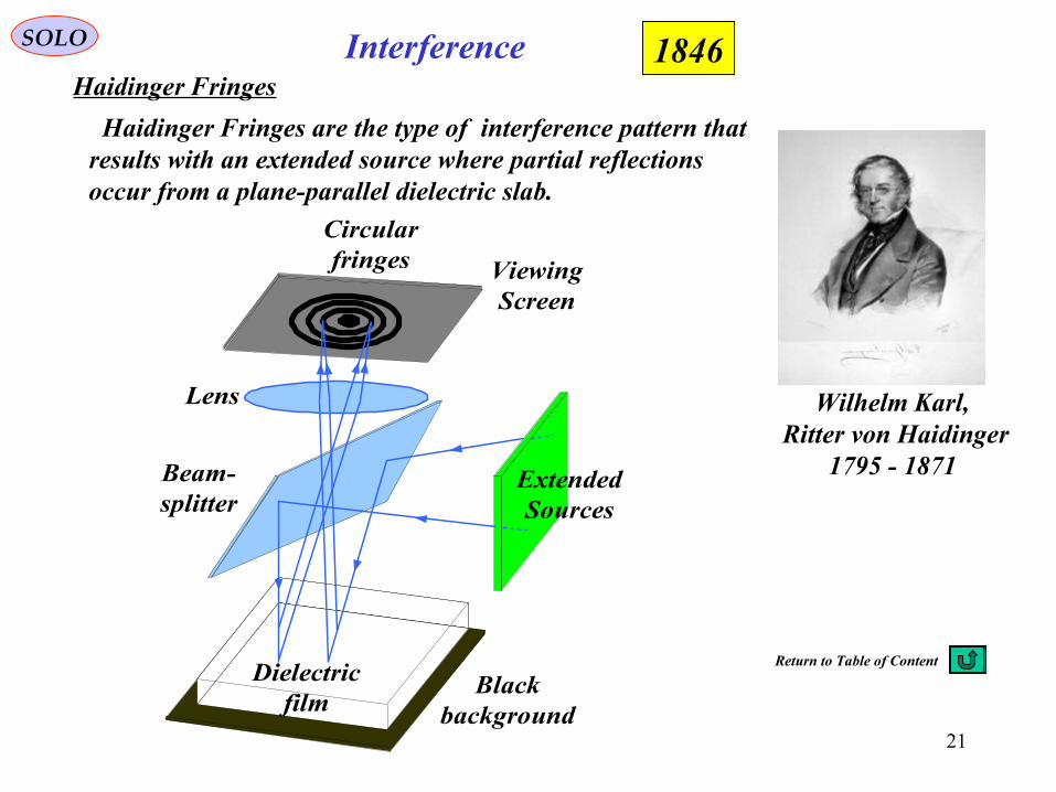
Haidinger Fringes are the type of interference pattern that results with an extended source where partial reflectionsoccur from a plane-parallel dielectric slab.
Return to Table of Content
22
SOLO
Fizeau Experiment
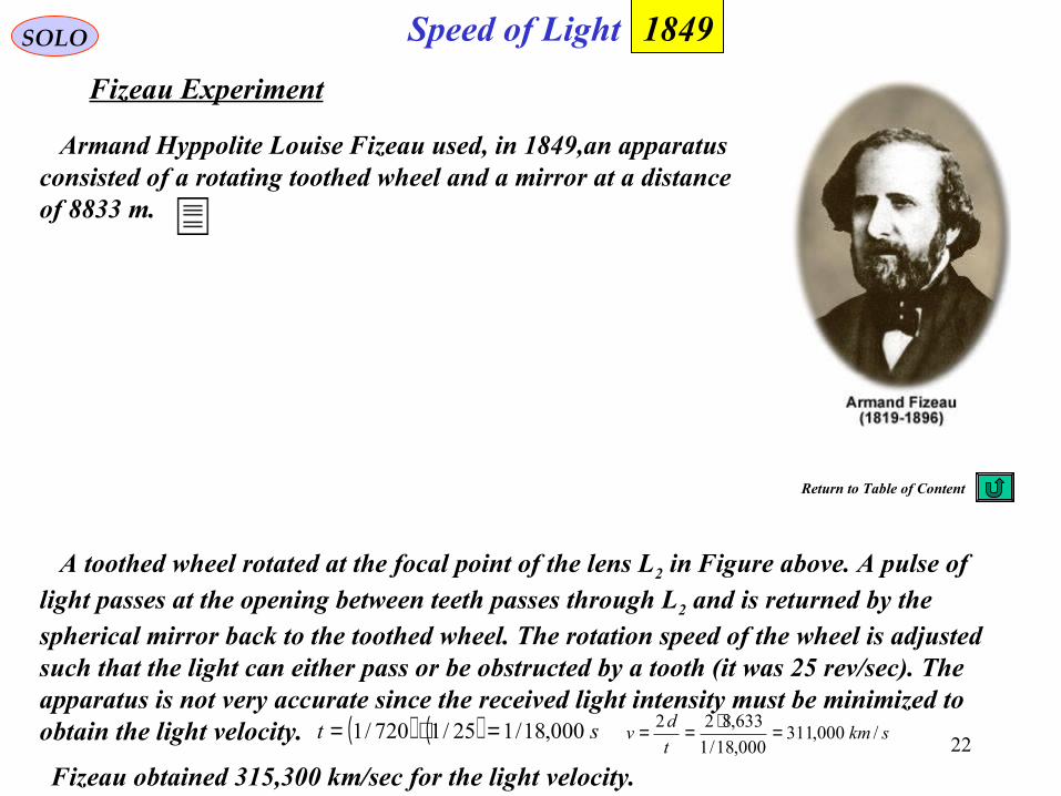
Armand Hyppolite Louise Fizeau used, in 1849,an apparatus consisted of a rotating toothed wheel and a mirror at a distance of 8833 m.
Speed of Light
A toothed wheel rotated at the focal point of the lens L2 in Figure above. A pulse oflight passes at the opening between teeth passes through L2 and is returned by thespherical mirror back to the toothed wheel. The rotation speed of the wheel is adjustedsuch that the light can either pass or be obstructed by a tooth (it was 25 rev/sec). The apparatus is not very accurate since the received light intensity must be minimized to obtain the light velocity.
Fizeau obtained 315,300 km/sec for the light velocity.
( ) ( ) st 000,18/125/1720/1 =⋅= skmt
dv /000,311
000,18/1
633,822 =⋅==
1849
Return to Table of Content
23
InterferenceSOLO
Jamin’s Interferometer
1856
J. Jamin, C.R. Acad. Sci. Paris, 42, p.482, 1856
Jules Célestin Jamin1818 - 1886
S
2T
1T 1C
2CD
D
1C 2C
E
1G
2G
1
2
Jamin's Interferometer
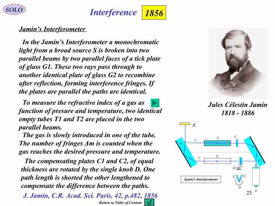
In the Jamin’s Interferometer a monochromaticlight from a broad source S is broken into two parallel beams by two parallel faces of a tick plate of glass G1. These two rays pass through to another identical plate of glass G2 to recombine after reflection, forming interference fringes. If the plates are parallel the paths are identical.
To measure the refractive index of a gas asfunction of presure and temperature, two identicalempty tubes T1 and T2 are placed in the twoparallel beams. The gas is slowly introduced in one of the tube.The number of fringes Δm is counted when the gas reaches the desired pressure and temperature. The compensating plates C1 and C2, of equalthickness are rotated by the single knob D. Onepath length is shorted the other lengthened tocompensate the difference between the paths.
Return to Table of Content
24
SOLO
Fizeau Experiment in Moving Media
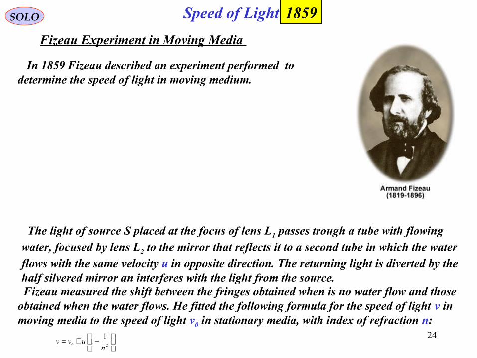
In 1859 Fizeau described an experiment performed to determine the speed of light in moving medium.
Speed of Light
The light of source S placed at the focus of lens L1 passes trough a tube with flowing water, focused by lens L2 to the mirror that reflects it to a second tube in which the water flows with the same velocity u in opposite direction. The returning light is diverted by thehalf silvered mirror an interferes with the light from the source.
Fizeau measured the shift between the fringes obtained when is no water flow and those obtained when the water flows. He fitted the following formula for the speed of light v in moving media to the speed of light v0 in stationary media, with index of refraction n:
−+=
20
11
nuvv
1859
25
InterferenceSOLO
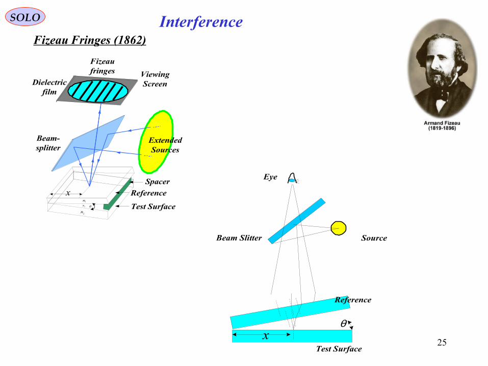
Fizeau Fringes (1862)
Spacer
Beam-splitter
ExtendedSources
ViewingScreenDielectric
film
Fizeaufringes
xα
1n
fn
2n
Reference
Test Surface
Test Surface
Reference
Beam Slitter
Eye
Source
θx
26
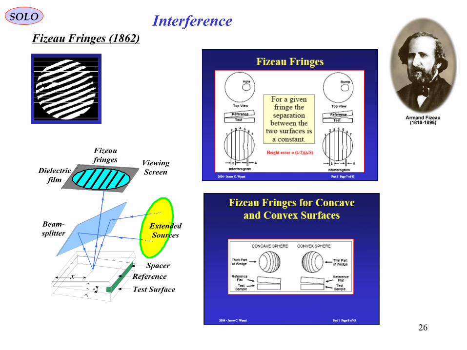
InterferenceSOLO
Fizeau Fringes (1862)
Spacer
Beam-splitter
ExtendedSources
ViewingScreenDielectric
film
Fizeaufringes
xα
1n
fn
2n
Reference
Test Surface
27
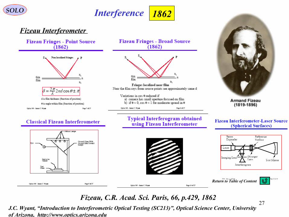
InterferenceSOLO
Fizeau Interferometer
1862
Fizeau, C.R. Acad. Sci. Paris, 66, p.429, 1862 J.C. Wyant, “Introduction to Interferometric Optical Testing (SC213)”, Optical Science Center, University of Arizona, http://www.optics.arizona.edu
Return to Table of Content
28
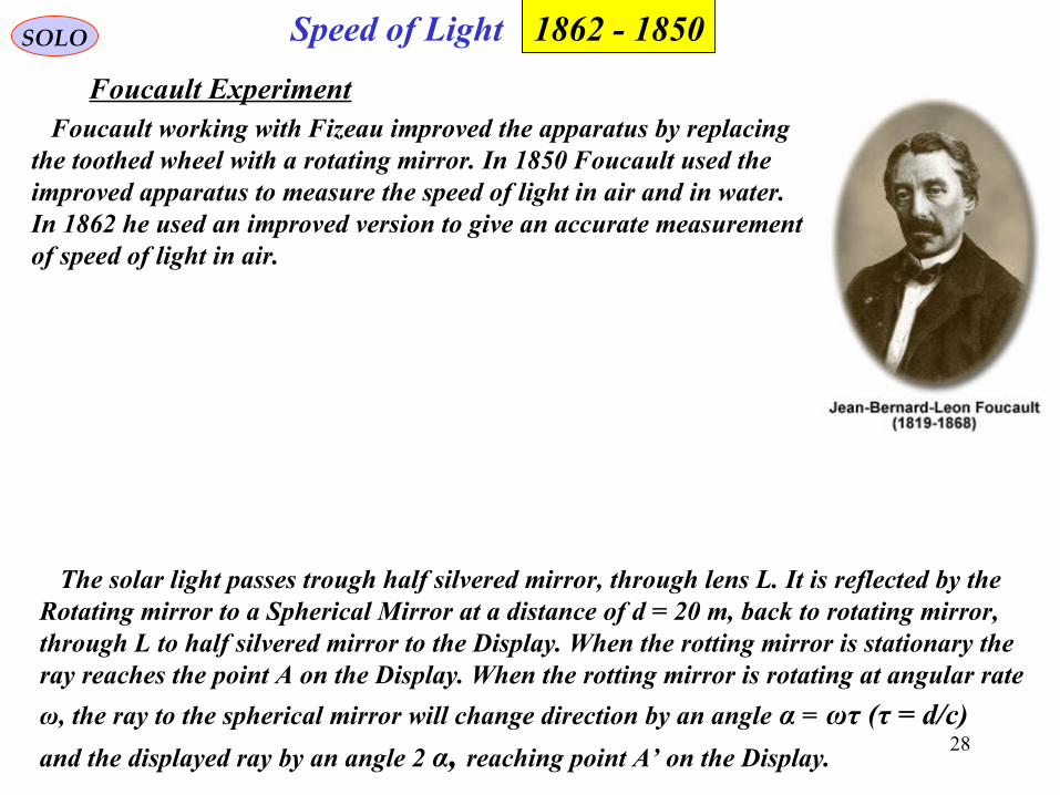
SOLO
Foucault Experiment Foucault working with Fizeau improved the apparatus by replacing the toothed wheel with a rotating mirror. In 1850 Foucault used theimproved apparatus to measure the speed of light in air and in water.In 1862 he used an improved version to give an accurate measurementof speed of light in air.
Speed of Light
The solar light passes trough half silvered mirror, through lens L. It is reflected by the Rotating mirror to a Spherical Mirror at a distance of d = 20 m, back to rotating mirror, through L to half silvered mirror to the Display. When the rotting mirror is stationary theray reaches the point A on the Display. When the rotting mirror is rotating at angular rate
ω, the ray to the spherical mirror will change direction by an angle α = ωτ (τ = d/c)
and the displayed ray by an angle 2 α, reaching point A’ on the Display.
1850 - 1862
29
SOLO
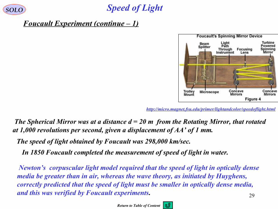
Foucault Experiment (continue – 1)
Speed of Light
http://micro.magnet.fsu.edu/primer/lightandcolor/speedoflight.html
The Spherical Mirror was at a distance d = 20 m from the Rotating Mirror, that rotated at 1,000 revolutions per second, given a displacement of AA’ of 1 mm.
The speed of light obtained by Foucault was 298,000 km/sec.
In 1850 Foucault completed the measurement of speed of light in water.
Newton’s corpuscular light model required that the speed of light in optically dense media be greater than in air, whereas the wave theory, as initiated by Huyghens, correctly predicted that the speed of light must be smaller in optically dense media,and this was verified by Foucault experiments.
Return to Table of Content

30
SOLO
Michelson Interferometer – Interference Fringes
Interference 1882 Nobel Prize 1907
José Antonio Diaz Navashttp://www.ugr.es/~jadiaz/
+
+++= π
λπ
f
yxdIIIII
22
2121 2cos2
cos2
I – intensity of the interference fringes
I1, I2 – intensity of the intensities of the two beamsλ – wavelengthd – path length difference between the two interferometers arms
x,y – coordinates of the focal plane of a lens of focal length f
“Interference Phenomena in a new form of Refractometer”,American J. of Science (3), 23, (1882), pp.392-400 andPhilos. Mag. (5) 13 (1892), pp.236-242
31
SOLO
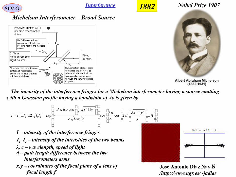
Michelson Interferometer – Broad Source
Interference 1882 Nobel Prize 1907
José Antonio Diaz Navashttp://www.ugr.es/~jadiaz/
[ ]
+
+
+∆
−++= πλπ
υπ
f
yxd
Logc
yxf
d
IIIII22
22
2121 2cos2
cos2
1cos
exp2
I – intensity of the interference fringes
I1, I2 – intensity of the intensities of the two beams
λ, c – wavelength, speed of lightd – path length difference between the two interferometers armsx,y – coordinates of the focal plane of a lens of focal length f
The intensity of the interference fringes for a Michelson interferometer having a source emitting with a Gaussian profile having a bandwidth of Δν is given by
32
SPECIAL RELATIVITY
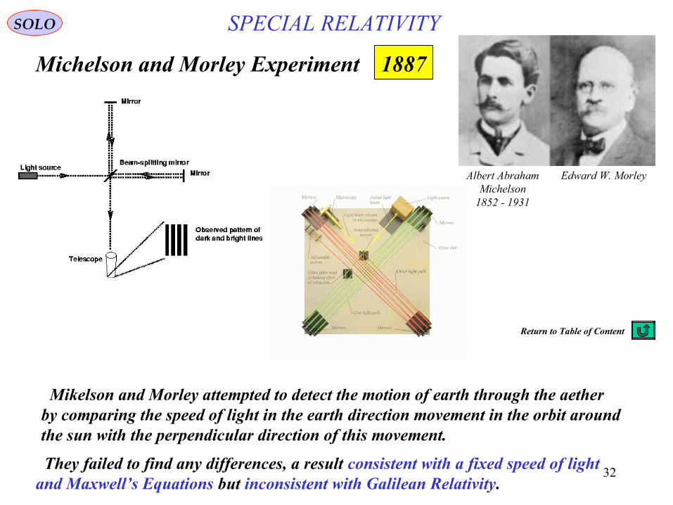
Michelson and Morley Experiment
Albert AbrahamMichelson
1852 - 1931
Edward W. Morley
Mikelson and Morley attempted to detect the motion of earth through the aether by comparing the speed of light in the earth direction movement in the orbit around the sun with the perpendicular direction of this movement.
They failed to find any differences, a result consistent with a fixed speed of lightand Maxwell’s Equations but inconsistent with Galilean Relativity.
SOLO
1887
Return to Table of Content
33
InterferometersSOLO
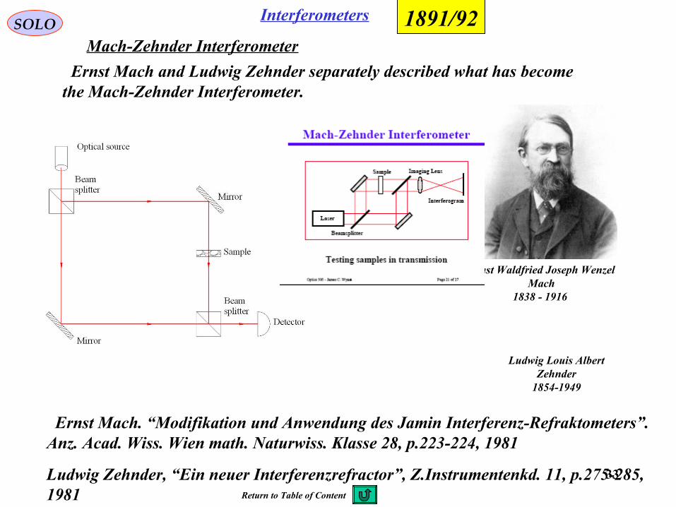
Ernst Mach and Ludwig Zehnder separately described what has become the Mach-Zehnder Interferometer.
1891/92
Ludwig Louis AlbertZehnder
1854-1949
Ernst Waldfried Joseph WenzelMach
1838 - 1916
Ernst Mach. “Modifikation und Anwendung des Jamin Interferenz-Refraktometers”.Anz. Acad. Wiss. Wien math. Naturwiss. Klasse 28, p.223-224, 1981
Ludwig Zehnder, “Ein neuer Interferenzrefractor”, Z.Instrumentenkd. 11, p.275-285,1981
Mach-Zehnder Interferometer
Return to Table of Content
34
InterferenceSOLO
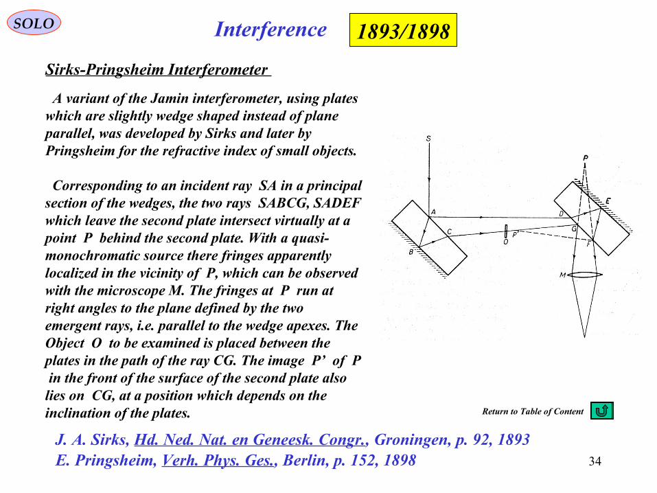
Sirks-Pringsheim Interferometer
1893/1898
J. A. Sirks, Hd. Ned. Nat. en Geneesk. Congr., Groningen, p. 92, 1893E. Pringsheim, Verh. Phys. Ges., Berlin, p. 152, 1898
A variant of the Jamin interferometer, using plates which are slightly wedge shaped instead of plane parallel, was developed by Sirks and later by Pringsheim for the refractive index of small objects.
Corresponding to an incident ray SA in a principal section of the wedges, the two rays SABCG, SADEF which leave the second plate intersect virtually at a point P behind the second plate. With a quasi-monochromatic source there fringes apparently localized in the vicinity of P, which can be observed with the microscope M. The fringes at P run at right angles to the plane defined by the two emergent rays, i.e. parallel to the wedge apexes. The Object O to be examined is placed between the plates in the path of the ray CG. The image P’ of P in the front of the surface of the second plate also lies on CG, at a position which depends on the inclination of the plates. Return to Table of Content
35
InterferenceSOLO
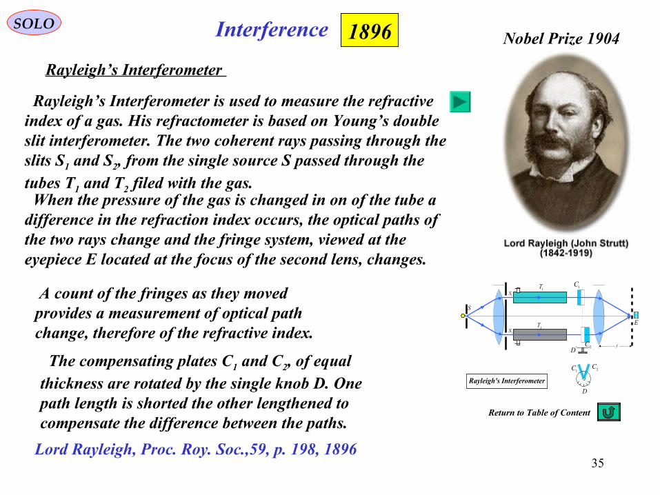
Rayleigh’s Interferometer
1896
Lord Rayleigh, Proc. Roy. Soc.,59, p. 198, 1896
Nobel Prize 1904
Rayleigh’s Interferometer is used to measure the refractiveindex of a gas. His refractometer is based on Young’s doubleslit interferometer. The two coherent rays passing through the slits S1 and S2, from the single source S passed through the tubes T1 and T2 filed with the gas. When the pressure of the gas is changed in on of the tube a difference in the refraction index occurs, the optical paths of the two rays change and the fringe system, viewed at the eyepiece E located at the focus of the second lens, changes.
A count of the fringes as they moved provides a measurement of optical path change, therefore of the refractive index.
The compensating plates C1 and C2, of equalthickness are rotated by the single knob D. Onepath length is shorted the other lengthened tocompensate the difference between the paths.
S
1S
2S2T
1T
f
1C
2CD
D
1C 2C
E
Rayleigh's Interferometer
Return to Table of Content
36
InterferenceSOLO
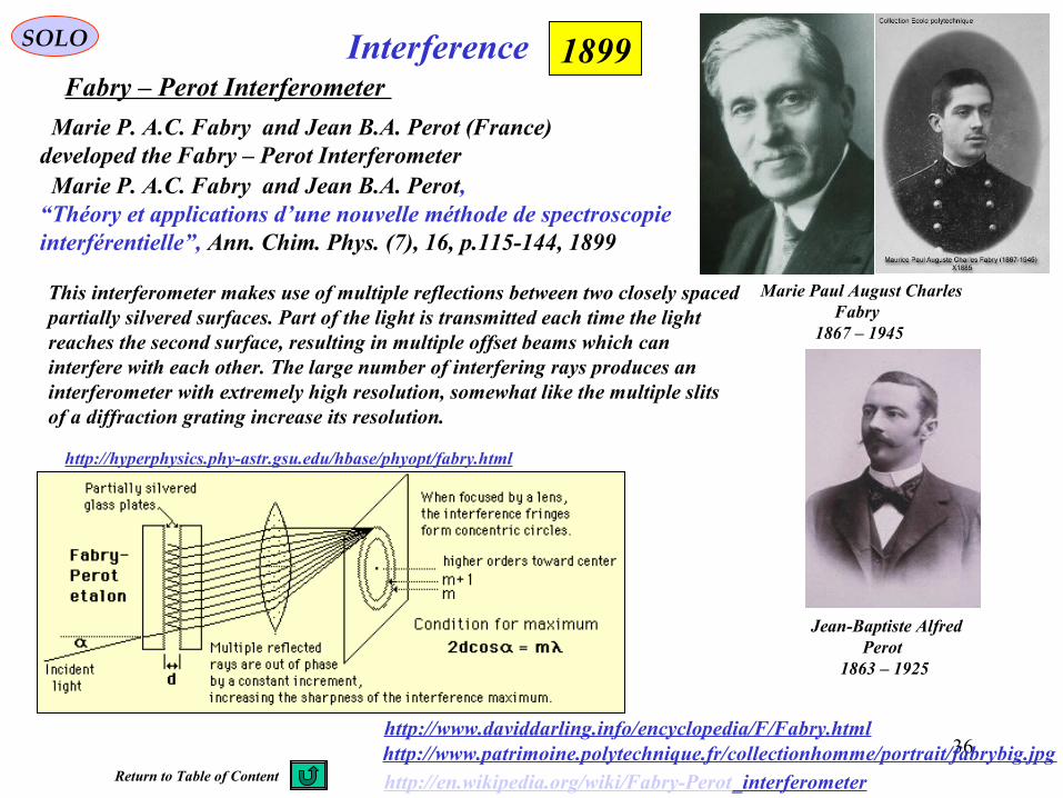
Fabry – Perot Interferometer 1899
http://en.wikipedia.org/wiki/Fabry-Perot_interferometer
Marie P. A.C. Fabry and Jean B.A. Perot (France) developed the Fabry – Perot Interferometer
Jean-Baptiste Alfred Perot
1863 – 1925
Marie P. A.C. Fabry and Jean B.A. Perot, “Théory et applications d’une nouvelle méthode de spectroscopie interférentielle”, Ann. Chim. Phys. (7), 16, p.115-144, 1899
http://www.daviddarling.info/encyclopedia/F/Fabry.html
Marie Paul August Charles Fabry
1867 – 1945
http://www.patrimoine.polytechnique.fr/collectionhomme/portrait/fabrybig.jpg
This interferometer makes use of multiple reflections between two closely spaced partially silvered surfaces. Part of the light is transmitted each time the light reaches the second surface, resulting in multiple offset beams which can interfere with each other. The large number of interfering rays produces an interferometer with extremely high resolution, somewhat like the multiple slits of a diffraction grating increase its resolution.
http://hyperphysics.phy-astr.gsu.edu/hbase/phyopt/fabry.html
Return to Table of Content
3737
Optics HistorySOLO
Sagnac, G. 1913. Comptes Rendus, 157:708 & 1410
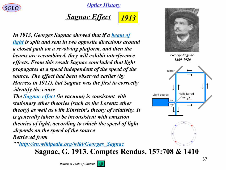
1913Sagnac Effect
In 1913, Georges Sagnac showed that if a beam of light is split and sent in two opposite directions around a closed path on a revolving platform, and then the beams are recombined, they will exhibit interference effects. From this result Sagnac concluded that light propagates at a speed independent of the speed of the source. The effect had been observed earlier (by Harress in 1911), but Sagnac was the first to correctly identify the cause.
The Sagnac effect (in vacuum) is consistent with stationary ether theories (such as the Lorentz ether theory) as well as with Einstein's theory of relativity. It is generally taken to be inconsistent with emission theories of light, according to which the speed of light depends on the speed of the source.
Retrieved from "http://en.wikipedia.org/wiki/Georges_Sagnac"
George Sagnac 1869-1926
Return to Table of Content
38
InterferenceSOLO
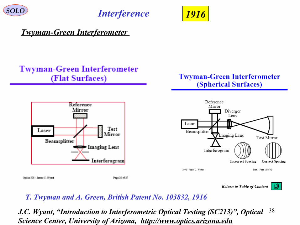
Twyman-Green Interferometer
1916
T. Twyman and A. Green, British Patent No. 103832, 1916
J.C. Wyant, “Introduction to Interferometric Optical Testing (SC213)”, Optical Science Center, University of Arizona, http://www.optics.arizona.edu
Return to Table of Content
39
SOLO
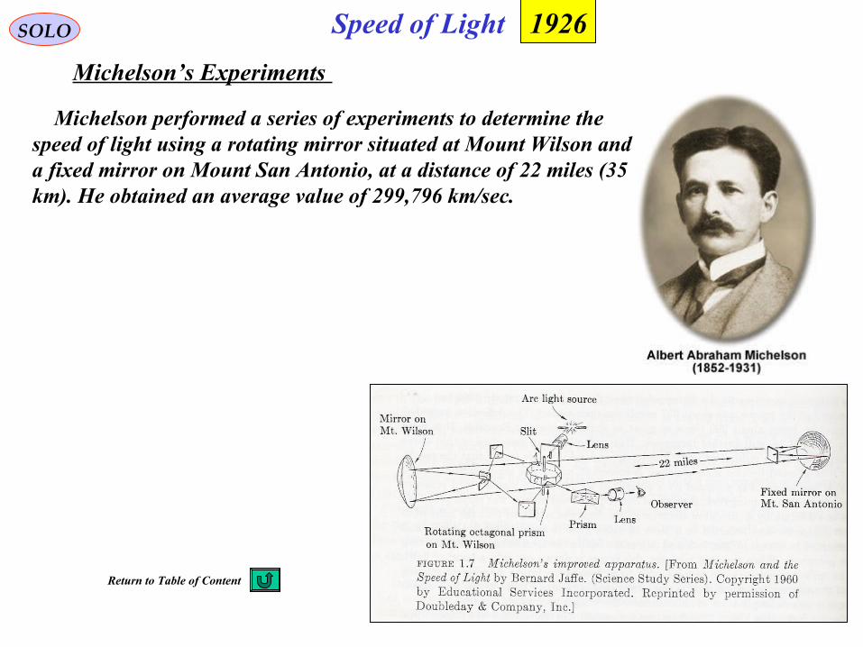
Michelson’s Experiments
Michelson performed a series of experiments to determine the speed of light using a rotating mirror situated at Mount Wilson and a fixed mirror on Mount San Antonio, at a distance of 22 miles (35 km). He obtained an average value of 299,796 km/sec.
Speed of Light 1926
Return to Table of Content
40
InterferenceSOLO
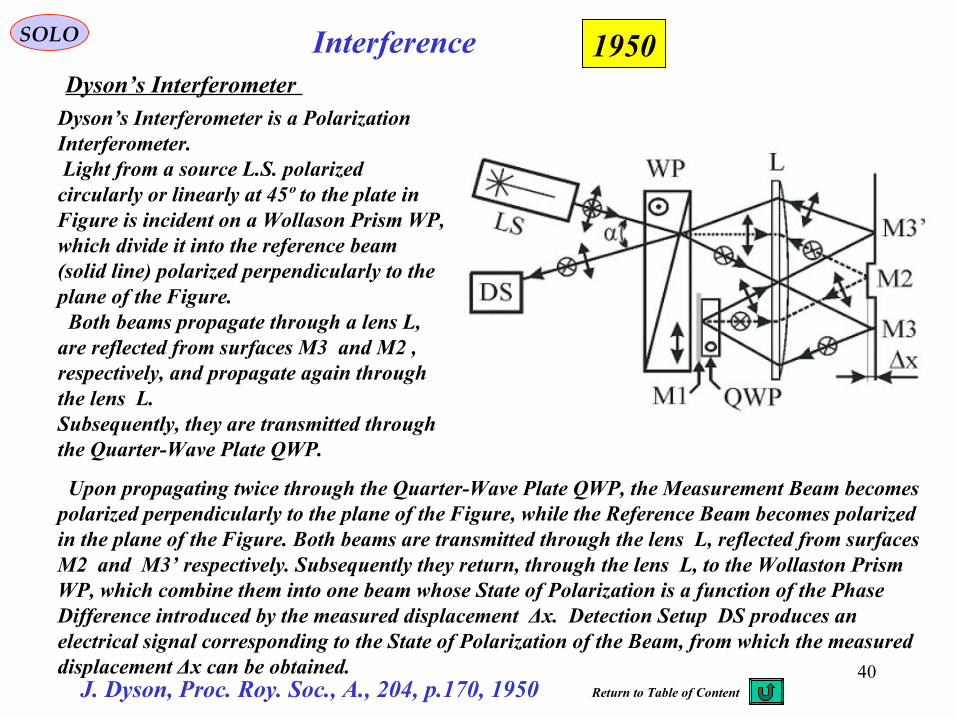
Dyson’s Interferometer
1950
J. Dyson, Proc. Roy. Soc., A., 204, p.170, 1950
Dyson’s Interferometer is a Polarization Interferometer. Light from a source L.S. polarized circularly or linearly at 45º to the plate in Figure is incident on a Wollason Prism WP, which divide it into the reference beam (solid line) polarized perpendicularly to the plane of the Figure. Both beams propagate through a lens L, are reflected from surfaces M3 and M2 , respectively, and propagate again through the lens L.Subsequently, they are transmitted through the Quarter-Wave Plate QWP.
Upon propagating twice through the Quarter-Wave Plate QWP, the Measurement Beam becomes polarized perpendicularly to the plane of the Figure, while the Reference Beam becomes polarized in the plane of the Figure. Both beams are transmitted through the lens L, reflected from surfaces M2 and M3’ respectively. Subsequently they return, through the lens L, to the Wollaston Prism WP, which combine them into one beam whose State of Polarization is a function of the Phase Difference introduced by the measured displacement Δx. Detection Setup DS produces an electrical signal corresponding to the State of Polarization of the Beam, from which the measured displacement Δx can be obtained.
Return to Table of Content
41
InterferenceSOLO
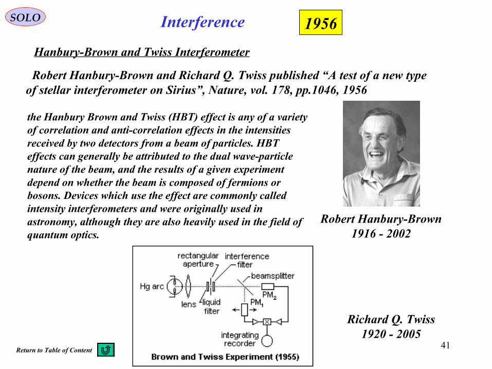
Hanbury-Brown and Twiss Interferometer
1956
Robert Hanbury-Brown and Richard Q. Twiss published “A test of a new typeof stellar interferometer on Sirius”, Nature, vol. 178, pp.1046, 1956
Richard Q. Twiss1920 - 2005
Robert Hanbury-Brown1916 - 2002
the Hanbury Brown and Twiss (HBT) effect is any of a variety of correlation and anti-correlation effects in the intensities received by two detectors from a beam of particles. HBT effects can generally be attributed to the dual wave-particle nature of the beam, and the results of a given experiment depend on whether the beam is composed of fermions or bosons. Devices which use the effect are commonly called intensity interferometers and were originally used in astronomy, although they are also heavily used in the field of quantum optics.
Return to Table of Content
42
InterferenceSOLO
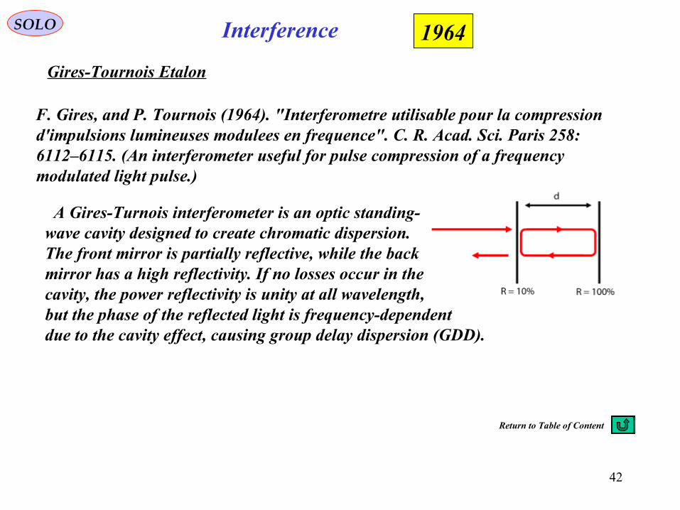
Gires-Tournois Etalon
1964
F. Gires, and P. Tournois (1964). "Interferometre utilisable pour la compression d'impulsions lumineuses modulees en frequence". C. R. Acad. Sci. Paris 258: 6112–6115. (An interferometer useful for pulse compression of a frequency modulated light pulse.)
A Gires-Turnois interferometer is an optic standing-wave cavity designed to create chromatic dispersion.The front mirror is partially reflective, while the backmirror has a high reflectivity. If no losses occur in thecavity, the power reflectivity is unity at all wavelength,but the phase of the reflected light is frequency-dependentdue to the cavity effect, causing group delay dispersion (GDD).
Return to Table of Content
43
InterferenceSOLO
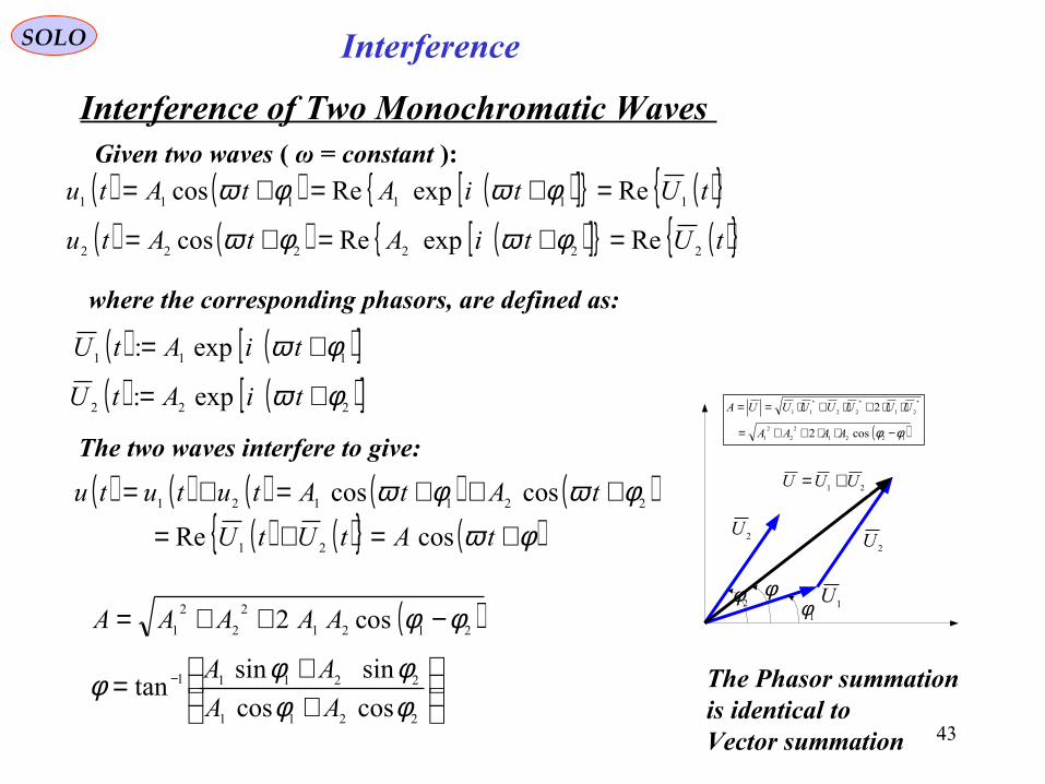
Interference of Two Monochromatic Waves Given two waves ( ω = constant ):
( ) ( ) ( )[ ]{ } ( ){ }tUtiAtAtu 111111 ReexpRecos =+=+= φωφω
where the corresponding phasors, are defined as:
( ) ( )[ ]111 exp: φω += tiAtU
The two waves interfere to give:
( ) ( ) ( ) ( ) ( )( ) ( ){ } ( )φω
φωφω+=+=
+++=+=
tAtUtU
tAtAtututu
cosRe
coscos
21
221121
( ) ( ) ( )[ ]{ } ( ){ }tUtiAtAtu 222222 ReexpRecos =+=+= φωφω
( ) ( )[ ]222 exp: φω += tiAtU
1U
2U
21 UUU +=
1φ2φ φ
( )1221
2
2
2
1
212211
cos2
2
φφ −⋅⋅++=
⋅⋅+⋅+⋅== ∗∗∗
AAAA
UUUUUUUA
2U
( )
++=
−++=
−
2211
22111
2121
2
2
2
1
coscos
sinsintan
cos2
φφφφφ
φφ
AA
AA
AAAAA
The Phasor summationis identical toVector summation
44
InterferenceSOLO
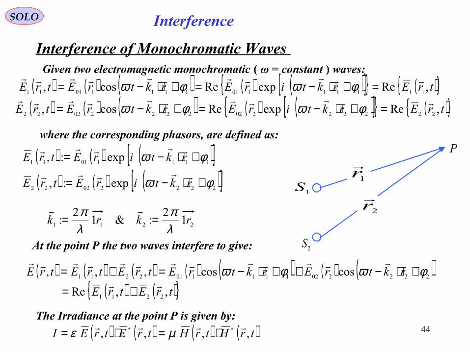
Interference of Monochromatic Waves Given two electromagnetic monochromatic ( ω = constant ) waves:
( ) ( ) ( ) ( ) ( )[ ]{ } ( ){ }trErktirErktrEtrE ,ReexpRecos, 1111110111110111
=+⋅−=+⋅−= φωφω
( ) ( ) ( ) ( ) ( )[ ]{ } ( ){ }trErktirErktrEtrE ,ReexpRecos, 2222220222220222
=+⋅−=+⋅−= φωφω
where the corresponding phasors, are defined as:
( ) ( ) ( )[ ]11110111 exp:, φω +⋅−= rktirEtrE
( ) ( ) ( )[ ]22220222 exp:, φω +⋅−= rktirEtrE
1S
2S
P
1r
2r
2211 12
:&12
: rkrkλπ
λπ ==
At the point P the two waves interfere to give:
( ) ( ) ( ) ( ) ( ) ( ) ( )( ) ( ){ }trEtrE
rktrErktrEtrEtrEtrE
,,Re
coscos,,,
2211
2222021111012211
+=
+⋅−++⋅−=+= φωφω
The Irradiance at the point P is given by:
( ) ( ) ( ) ( )trHtrHtrEtrEI ,,,, ∗∗ ⋅=⋅= µε
45
InterferenceSOLO
Interference of Monochromatic Waves
1S
2S
P
1r
2r
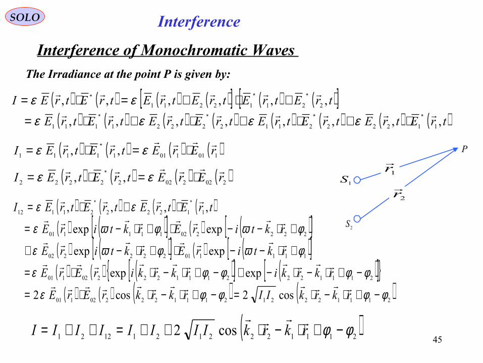
The Irradiance at the point P is given by:
( ) ( ) ( ) ( )[ ] ( ) ( )[ ]( ) ( ) ( ) ( ) ( ) ( ) ( ) ( )trEtrEtrEtrEtrEtrEtrEtrE
trEtrEtrEtrEtrEtrEI
,,,,,,,,
,,,,,,
1122221122221111
22112211
∗∗∗∗
∗∗∗
⋅+⋅+⋅+⋅=
+⋅+=⋅=
εεεεεε
( ) ( ) ( ) ( )10110111111 ,, rErEtrEtrEI
⋅=⋅= ∗ εε
( ) ( ) ( ) ( )20220222222 ,, rErEtrEtrEI
⋅=⋅= ∗ εε
( ) ( ) ( ) ( )( ) ( )[ ] ( ) ( )[ ]( ) ( )[ ] ( ) ( )[ ]( ) ( ) ( )[ ] ( )[ ]{ }
( ) ( ) ( ) ( )21112221211122202101
211122211122202101
111101222202
222202111101
1122221112
cos2cos2
expexp
expexp
expexp
,,,,
φφφφε
φφφφε
φωφωε
φωφωε
εε
−+⋅−⋅=−+⋅−⋅⋅=
−+⋅−⋅−+−+⋅−⋅⋅=
+⋅−−⋅+⋅−+
+⋅−−⋅+⋅−=
⋅+⋅= ∗∗
rkrkIIrkrkrErE
rkrkirkrkirErE
rktirErktirE
rktirErktirE
trEtrEtrEtrEI
( )21112221211221 cos2 φφ −+⋅−⋅++=++= rkrkIIIIIIII
46
InterferenceSOLO
Interference of Monochromatic Waves 1S
2S
P
1r
2r
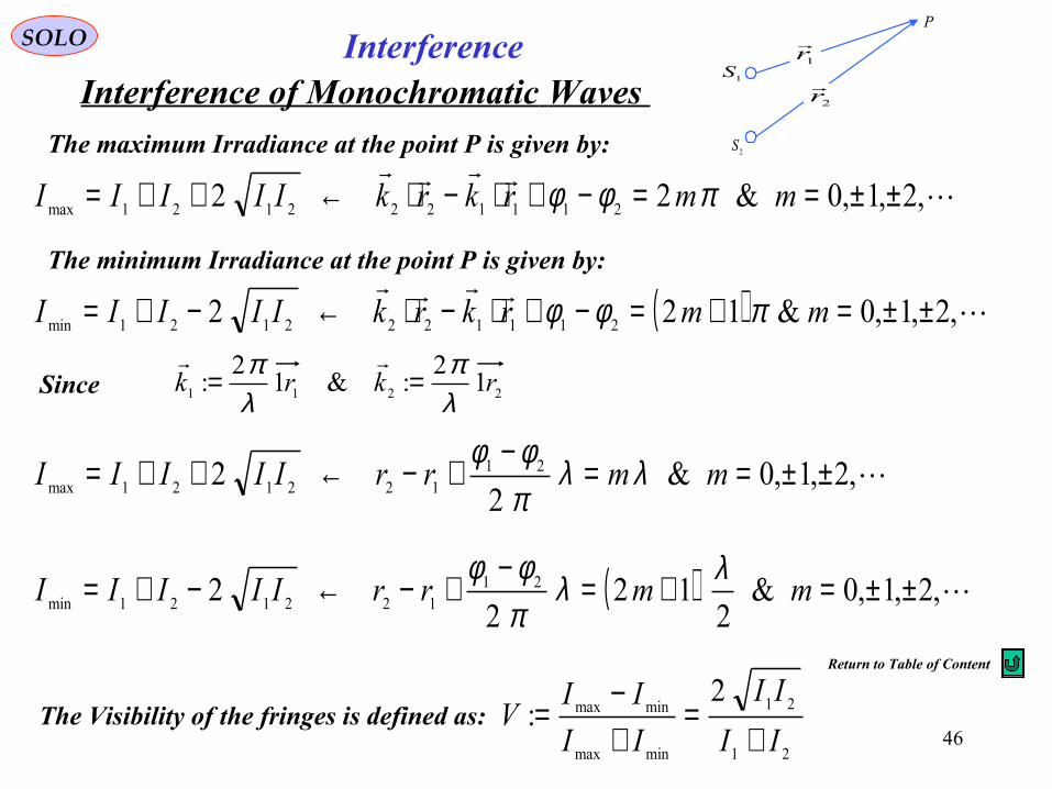
The maximum Irradiance at the point P is given by:
,2,1,0&22 2111222121max ±±==−+⋅−⋅←++= mmrkrkIIIII πφφ
The minimum Irradiance at the point P is given by:
( )
,2,1,0&122 2111222121min ±±=+=−+⋅−⋅←−+= mmrkrkIIIII πφφ
2211 12
:&12
: rkrkλπ
λπ ==
Since
,2,1,0&2
2 21122121max ±±==−+−←++= mmrrIIIII λλ
πφφ
( ) ,2,1,0&2
122
2 21122121min ±±=+=−+−←−+= mmrrIIIII
λλπφφ
The Visibility of the fringes is defined as:21
21
minmax
minmax2
:II
II
II
IIV
+=
+−
=
Return to Table of Content
47
InterferenceSOLO
Billet’s Split Lens
Meslin’s Experiment
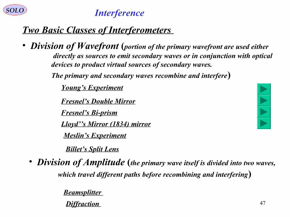
Two Basic Classes of Interferometers
• Division of Wavefront (portion of the primary wavefront are used either directly as sources to emit secondary waves or in conjunction with opticaldevices to product virtual sources of secondary waves.
The primary and secondary waves recombine and interfere)
• Division of Amplitude (the primary wave itself is divided into two waves,
which travel different paths before recombining and interfering)
Beamsplitter
Diffraction
Young’s Experiment
Fresnel’s Double Mirror
Fresnel’s Bi-prism
Lloyd’’s Mirror (1834) mirror
48
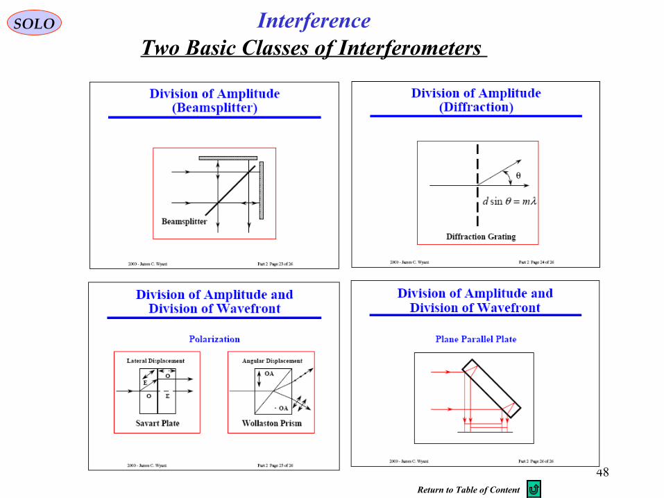
Two Basic Classes of Interferometers InterferenceSOLO
Return to Table of Content
49
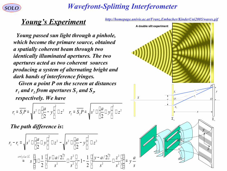
Wavefront-Splitting Interferometer SOLO
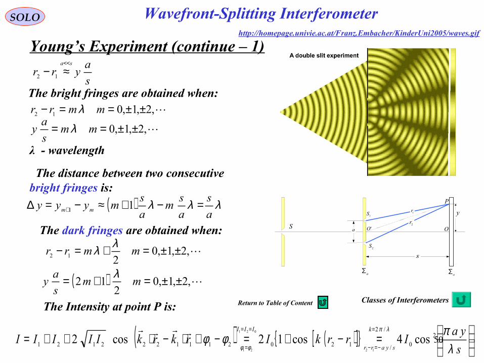
Young’s Experiment
1r
2r
s
a
y
2S
1S
P
OS 'O
aΣoΣ
Young passed sun light through a pinhole,which become the primare source, obtaineda spatially coherent beam through twoidentically illuminated apertures. The twoapertures acted as two coherent sourcesproducing a system of alternating bright anddark bands of interference fringes. Given a point P on the screen at distancesr1 and r2 from apertures S1 and S2, respectively. We have
The path difference is:
2
2
2
22
2
2
2
11 22zy
asPSrzy
asPSr +
++==+
−+==
( ) ( ) ( )s
ay
s
z
s
ay
s
z
s
ays
zya
szya
srr
ays
=
+−−−
+++≈
+
−+−+
++=−
+>>
2
2
2
2
2
2
2
22/
2
2
22
2
2
12
2/
2
11
2/
2
11
22
http://homepage.univie.ac.at/Franz.Embacher/KinderUni2005/waves.gif
2S
1S
y
z
50
SOLO
Young’s Experiment (continue – 1)
s
ayrr
sa<<
≈− 12
The bright fringes are obtained when:,2,1,012 ±±==− mmrr λ
,2,1,0 ±±== mms
ay λ
The distance between two consecutive bright fringes is:
( ) λλλa
s
a
sm
a
smyyy mm =−+≈−=∆ + 11
The dark fringes are obtained when:
,2,1,0212 ±±=+=− mmrrλλ
( ) ,2,1,02
12 ±±=+= mms
ay
λ
λ - wavelength
The Intensity at point P is:
( ) ( )[ ]{ }
=−+=−+⋅−⋅++=
=
−=−
==
= s
yaIrrkIrkrkIIIII
k
syarr
III
λπφφ
λπ
φφ
2
0
/2
/1202111222121 cos4cos12cos212
021
21
1r
2r
s
a
y
2S
1S
P
OS 'O
aΣoΣ
http://homepage.univie.ac.at/Franz.Embacher/KinderUni2005/waves.gif
Wavefront-Splitting Interferometer
Classes of InterferometersReturn to Table of Content
51
SOLO
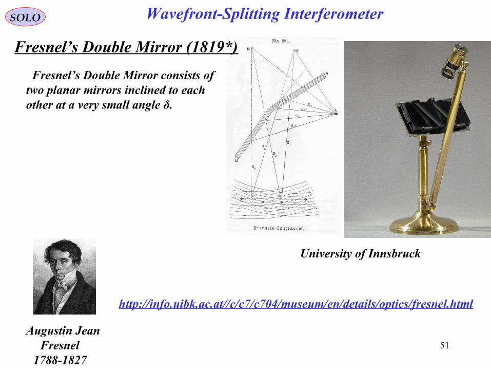
http://info.uibk.ac.at//c/c7/c704/museum/en/details/optics/fresnel.html
University of Innsbruck
Fresnel’s Double Mirror consists oftwo planar mirrors inclined to eachother at a very small angle δ.
Wavefront-Splitting Interferometer
Augustin Jean Fresnel
1788-1827
Fresnel’s Double Mirror (1819*)
52
SOLO
Fresnel’s Double Mirror (continue – 1)
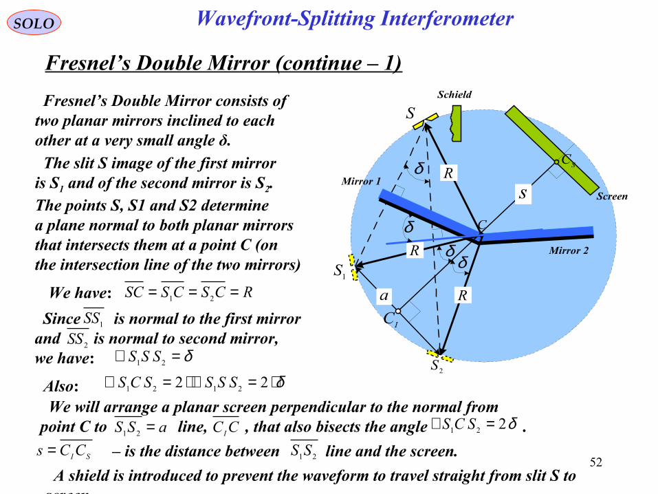
Fresnel’s Double Mirror consists oftwo planar mirrors inclined to eachother at a very small angle δ. The slit S image of the first mirroris S1 and of the second mirror is S2.The points S, S1 and S2 determinea plane normal to both planar mirrorsthat intersects them at a point C (onthe intersection line of the two mirrors)
We have: RCSCSSC === 21
δ=∠ 21 SSS
Since is normal to the first mirrorand is normal to second mirror, we have:
1SS
2SS
Also: δ⋅=∠⋅=∠ 22 2121 SSSSCS
a1S
2S
S
R
R
R
Screen
Schield
Mirror 2
C
δ
δδ
δ
sMirror 1
SC
IC
We will arrange a planar screen perpendicular to the normal from point C to line, , that also bisects the angle .aSS =21
δ221 =∠ SCSCC I
– is the distance between line and the screen.21SSSI CCs = A shield is introduced to prevent the waveform to travel straight from slit S to screen.
Wavefront-Splitting Interferometer
53
SOLO
Fresnel’s Double Mirror (continue – 2)
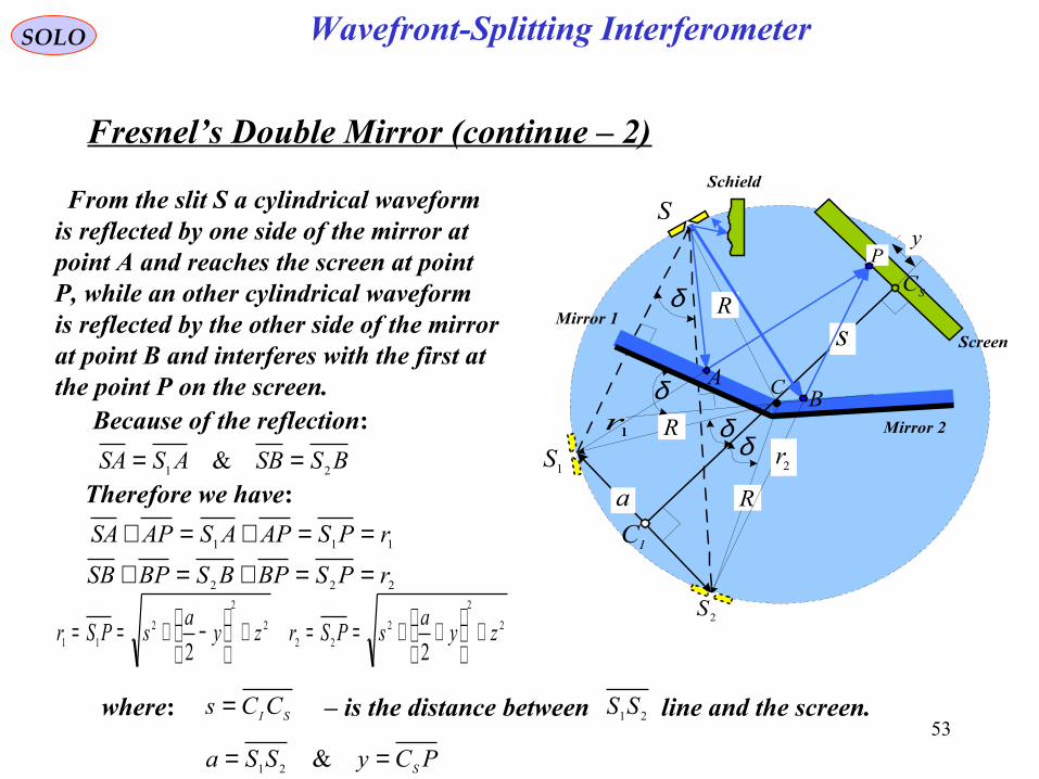
From the slit S a cylindrical waveformis reflected by one side of the mirror atpoint A and reaches the screen at pointP, while an other cylindrical waveformis reflected by the other side of the mirrorat point B and interferes with the first atthe point P on the screen.
Because of the reflection:
BSSBASSA 21 & == Therefore we have:
111 rPSAPASAPSA ==+=+
222 rPSBPBSBPSB ==+=+
a1S
2S
S
AB
P
R
R
R
Screen
Schield
Mirror 2
C
δ
δδ
δ
s
2r1r
Mirror 1
y
SC
IC
where: – is the distance between line and the screen.21SSSI CCs =
PCySSa S== &21
2
2
2
22
2
2
2
11 22zy
asPSrzy
asPSr +
++==+
−+==
Wavefront-Splitting Interferometer
54
SP
R
Screen
Schield
Mirror 2
C
δ
sMirror 1
Slit
SCy
z
SOLO
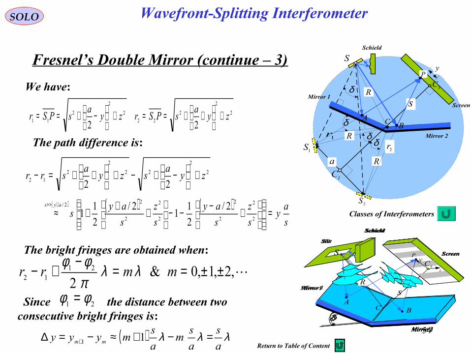
Fresnel’s Double Mirror (continue – 3)
We have:
The path difference is:
The bright fringes are obtained when:
( ) λλλa
s
a
sm
a
smyyy mm =−+≈−=∆ + 11
a1S
2S
S
AB
P
R
R
R
Screen
Schield
Mirror 2
C
δ
δδ
δ
s
2r1r
Mirror 1
y
SC
IC
S
AB
P
R
Screen
Schield
Mirror 2
C
δ
sMirror 1
Slit
SCy
z
S
AB
P
R
Screen
Schield
Mirror 2
C
δ
sMirror 1
Slit
ySC
z
P
2
2
2
22
2
2
2
11 22zy
asPSrzy
asPSr +
++==+
−+==
( ) ( ) ( )s
ay
s
z
s
ay
s
z
s
ays
zya
szya
srr
ays
=
+−−−
+++≈
+
−+−+
++=−
+>>
2
2
2
2
2
2
2
22/
2
2
22
2
2
12
2/
2
11
2/
2
11
22
Wavefront-Splitting Interferometer
,2,1,0&2
2112 ±±==−+− mmrr λλ
πφφ
Since the distance between two consecutive bright fringes is:
21 φφ =
Classes of Interferometers
Return to Table of Content
55
SOLO
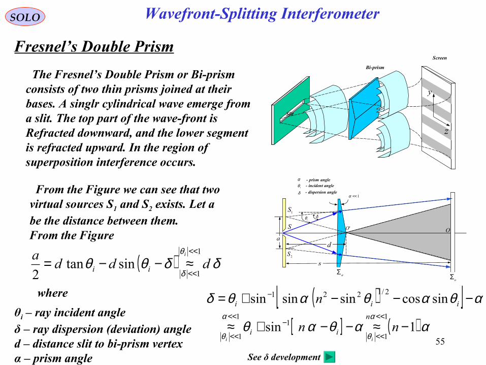
Fresnel’s Double Prism
The Fresnel’s Double Prism or Bi-prism consists of two thin prisms joined at their bases. A singlr cylindrical wave emerge froma slit. The top part of the wave-front is Refracted downward, and the lower segment is refracted upward. In the region of superposition interference occurs.
Screen
Bi-prism
Slit
y
z
δ
s
a
2S
1S
OS 'O
aΣoΣ
1<<α
iθ
d
iθ - incident angle
δ - dispersion angle
α - prism angle
From the Figure we can see that twovirtual sources S1 and S2 exists. Let abe the distance between them.From the Figure
( ) δδθθθ
δddd
a i
ii
1
1sintan
2
<<
<<≈−−=
where
θi – ray incident angleδ – ray dispersion (deviation) angled – distance slit to bi-prism vertexα – prism angle
( )[ ][ ] ( ) ααθαθ
αθαθαθδα
θ
α
θ1sin
sincossinsinsin1
1
11
1
2/1221
−≈−−+≈
−−−+=<<
<<
−<<
<<
−
nn
nn
ii
iii
ii
See δ development
Wavefront-Splitting Interferometer
56
SOLO
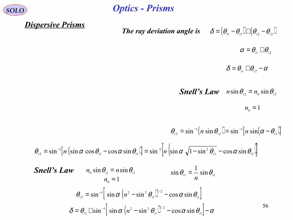
Dispersive Prisms( ) ( )2211 itti θθθθδ −+−=
21 it θθα +=
αθθδ −+= 21 ti
202 sinsin ti nn θθ =Snell’s Law
10 ≈n
( ) ( )[ ]1
1
2
1
2 sinsinsinsin tit nn θαθθ −== −−
( )[ ] ( )[ ]11
21
11
1
2 sincossin1sinsinsincoscossinsin ttttt nn θαθαθαθαθ −−=−= −−
Snell’s Law 110 sinsin ti nn θθ =11 sin
1sin it n
θθ =10 ≈n
( )[ ]12/1
1
221
2 sincossinsinsin iit n θαθαθ −−= −
( )[ ] αθαθαθδ −−−+= −1
2/1
1
221
1 sincossinsinsin iii n
The ray deviation angle is
Optics - Prisms
57
SOLO
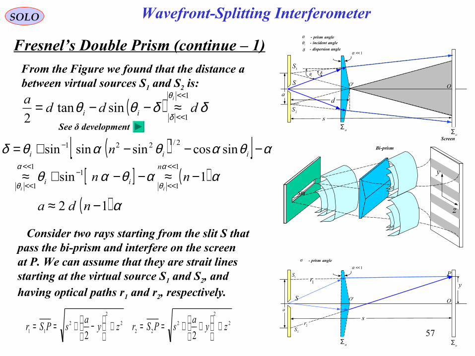
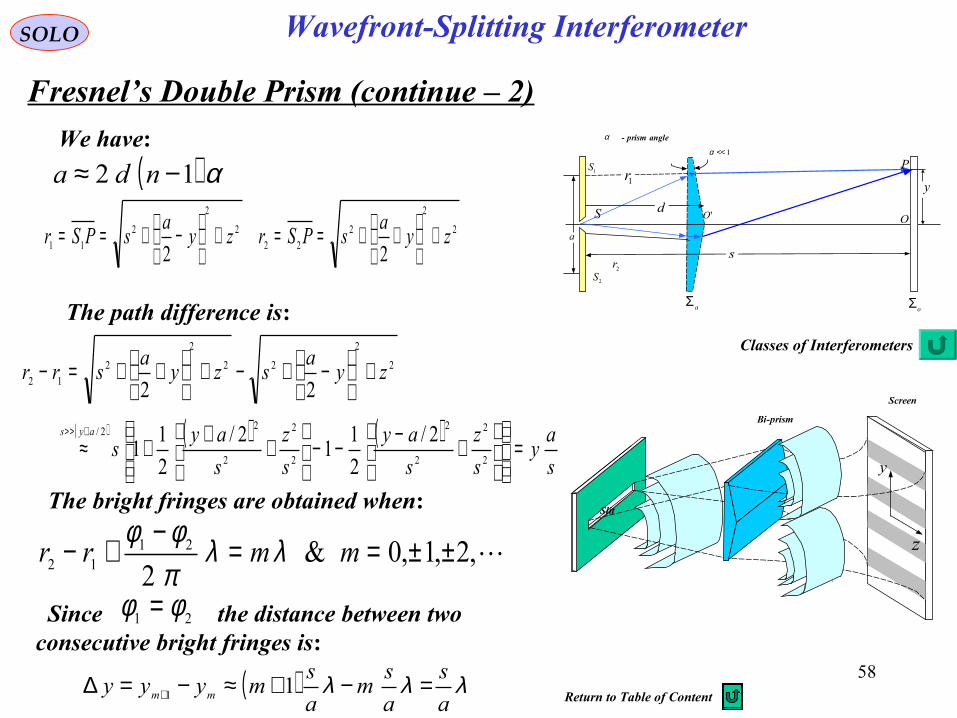
Fresnel’s Double Prism (continue – 1)
From the Figure we found that the distance abetween virtual sources S1 and S2 is:
( ) δδθθθ
δddd
a i
ii
1
1sintan
2
<<
<<≈−−=
( )[ ][ ] ( ) ααθαθ
αθαθαθδα
θ
α
θ1sin
sincossinsinsin1
1
11
1
2/1221
−≈−−+≈
−−−+=<<
<<
−<<
<<
−
nn
nn
ii
iii
ii
See δ development
( ) α12 −≈ nda
s
a
y
2S
1S P
OS 'O
aΣoΣ
1<<α
α - prism angle
1r
2r
Screen
Bi-prism
Slit
y
z
Consider two rays starting from the slit S thatpass the bi-prism and interfere on the screen at P. We can assume that they are strait lines starting at the virtual source S1 and S2, andhaving optical paths r1 and r2, respectively.
2
2
2
22
2
2
2
11 22zy
asPSrzy
asPSr +
++==+
−+==
Wavefront-Splitting Interferometer
δ
s
a
2S
1S
OS 'O
aΣoΣ
1<<α
iθ
d
iθ - incident angle
δ - dispersion angle
α - prism angle
58
SOLO
Fresnel’s Double Prism (continue – 2)
( ) α12 −≈ nda
s
a
y
2S
1S P
OS 'O
aΣoΣ
1<<α
α - prism angle
1r
2r
d
Screen
Bi-prism
Slit
y
z
2
2
2
22
2
2
2
11 22zy
asPSrzy
asPSr +
++==+
−+==
The path difference is:
The bright fringes are obtained when:
( ) λλλa
s
a
sm
a
smyyy mm =−+≈−=∆ + 11
( ) ( ) ( )s
ay
s
z
s
ay
s
z
s
ays
zya
szya
srr
ays
=
+−−−
+++≈
+
−+−+
++=−
+>>
2
2
2
2
2
2
2
22/
2
2
22
2
2
12
2/
2
11
2/
2
11
22
We have:
Wavefront-Splitting Interferometer
,2,1,0&2
2112 ±±==−+− mmrr λλ
πφφ
Since the distance between two consecutive bright fringes is:
21 φφ =
Classes of Interferometers
Return to Table of Content
59
SOLO
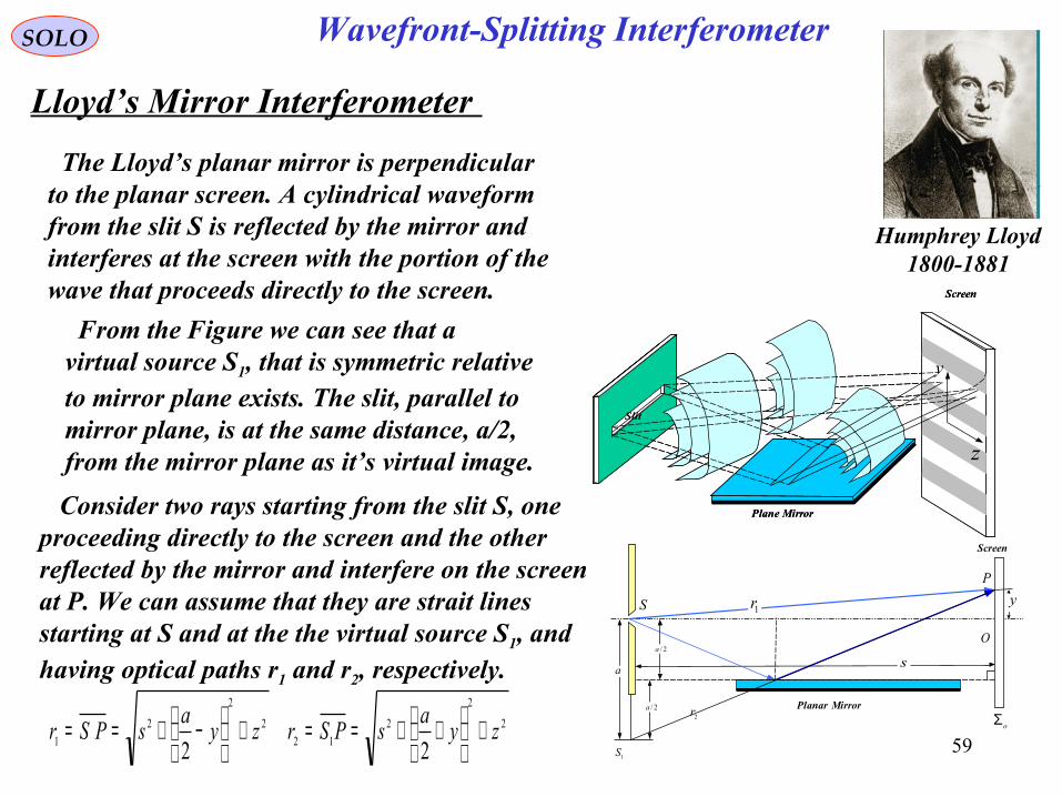
Lloyd’s Mirror Interferometer
The Lloyd’s planar mirror is perpendicularto the planar screen. A cylindrical waveformfrom the slit S is reflected by the mirror andinterferes at the screen with the portion of thewave that proceeds directly to the screen. Screen
Plane Mirror
Slit
y
z
From the Figure we can see that avirtual source S1, that is symmetric relativeto mirror plane exists. The slit, parallel tomirror plane, is at the same distance, a/2,from the mirror plane as it’s virtual image.
Wavefront-Splitting Interferometer
sa
y
1S
P
O
S
oΣ
1r
2r2/a
2/a
Planar Mirror
Screen
Screen
Plane Mirror
Slit
y
z
Consider two rays starting from the slit S, oneproceeding directly to the screen and the otherreflected by the mirror and interfere on the screen at P. We can assume that they are strait lines starting at S and at the the virtual source S1, andhaving optical paths r1 and r2, respectively.
2
2
2
12
2
2
2
1 22zy
asPSrzy
asPSr +
++==+
−+==
Humphrey Lloyd1800-1881
60
SOLO
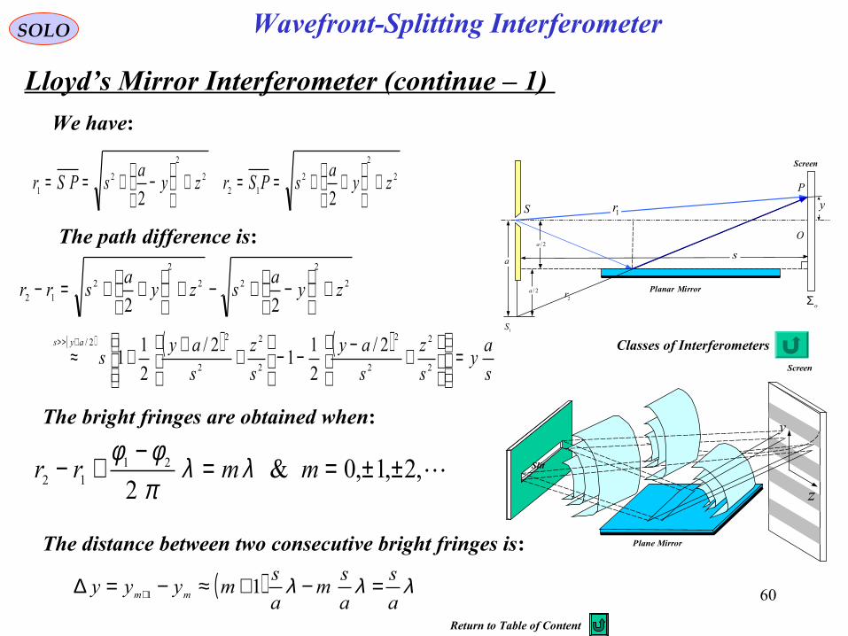
Lloyd’s Mirror Interferometer (continue – 1)
Wavefront-Splitting Interferometer
sa
y
1S
P
O
S
oΣ
1r
2r2/a
2/a
Planar Mirror
Screen
Screen
Plane Mirror
Slit
y
z
The path difference is:
The bright fringes are obtained when:
The distance between two consecutive bright fringes is:
( ) λλλa
s
a
sm
a
smyyy mm =−+≈−=∆ + 11
( ) ( ) ( )s
ay
s
z
s
ay
s
z
s
ays
zya
szya
srr
ays
=
+−−−
+++≈
+
−+−+
++=−
+> >
2
2
2
2
2
2
2
22/
2
2
22
2
2
12
2/
2
11
2/
2
11
22
We have:
2
2
2
12
2
2
2
1 22zy
asPSrzy
asPSr +
++==+
−+==
,2,1,0&2
2112 ±±==−+− mmrr λλ
πφφ
Classes of Interferometers
Return to Table of Content
61
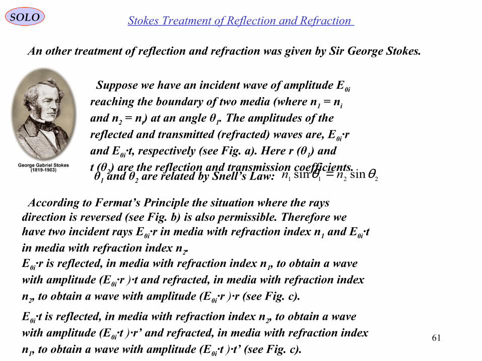
Stokes Treatment of Reflection and Refraction SOLO
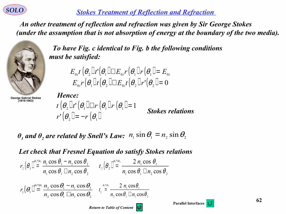
An other treatment of reflection and refraction was given by Sir George Stokes.
Suppose we have an incident wave of amplitude E0i
reaching the boundary of two media (where n1 = ni and n2 = nt) at an angle θ1. The amplitudes of the reflected and transmitted (refracted) waves are, E0i·r and E0i·t, respectively (see Fig. a). Here r (θ1) and t (θ2) are the reflection and transmission coefficients.
According to Fermat’s Principle the situation where the rays direction is reversed (see Fig. b) is also permissible. Therefore we have two incident rays E0i·r in media with refraction index n1 and E0i·t in media with refraction index n2.E0i·r is reflected, in media with refraction index n1, to obtain a wave with amplitude (E0i·r )·t and refracted, in media with refraction index n2, to obtain a wave with amplitude (E0i·r )·r (see Fig. c).
E0i·t is reflected, in media with refraction index n2, to obtain a wave with amplitude (E0i·t )·r’ and refracted, in media with refraction index n1, to obtain a wave with amplitude (E0i·t )·t’ (see Fig. c).
θ1 and θ2 are related by Snell’s Law: 2211 sinsin θθ nn =
62
Stokes Treatment of Reflection and Refraction SOLO
An other treatment of reflection and refraction was given by Sir George Stokes(under the assumption that is not absorption of energy at the boundary of the two media).
To have Fig. c identical to Fig. b the following conditions must be satisfied:
( ) ( ) ( ) ( ) iii ErrEttE 0110120 ' =+ θθθθ( ) ( ) ( ) ( ) 0' 220210 =+ θθθθ rtEtrE ii
Hence:
( ) ( ) ( ) ( )( ) ( )12
1112
'
1'
θθθθθθ
rr
rrtt
−==+
Stokes relations
θ1 and θ2 are related by Snell’s Law: 2211 sinsin θθ nn =
Let check that Fresnel Equation do satisfy Stokes relations
( )2211
112 coscos
cos221
θθθθ
µµ
nn
nt
+==
⊥
2112
11|| coscos
cos221
θθθµµ
nn
nt
+==
( )2211
22111 coscos
coscos21
θθθθθ
µµ
nn
nnr
+−
==
⊥
( )2112
21121|| coscos
coscos21
θθθθθ
µµ
nn
nnr
+−=
=
Parallel InterfacesReturn to Table of Content
63
SOLO
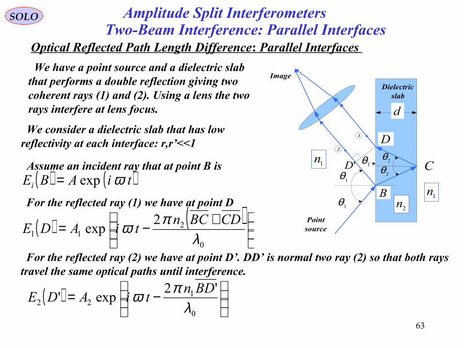
Optical Reflected Path Length Difference: Parallel Interfaces Two-Beam Interference: Parallel Interfaces
We have a point source and a dielectric slabthat performs a double reflection giving two coherent rays (1) and (2). Using a lens the tworays interfere at lens focus.
'D1θ
1θ
1θ 2θ2θ
d
C
B
D
1n
2n1n
Pointsource
Image
1
2
Dielectricslab
We consider a dielectric slab that has low reflectivity at each interface: r,r’<<1
Assume an incident ray that at point B is( ) ( )tiABEi ωexp=
For the reflected ray (1) we have at point D
( )
−=
0
122
'2exp'
λπω BDn
tiADE
For the reflected ray (2) we have at point D’. DD’ is normal two ray (2) so that both raystravel the same optical paths until interference.
( ) ( )
+−=0
211
2exp
λπω CDBCn
tiADE
Amplitude Split Interferometers
64
SOLO
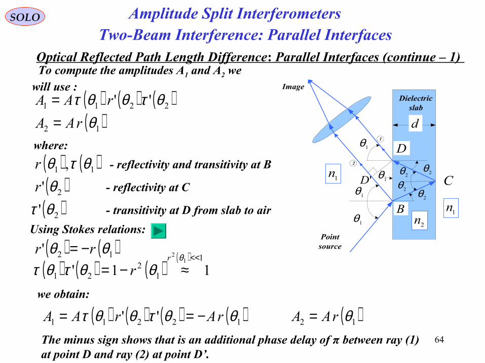
Optical Reflected Path Length Difference: Parallel Interfaces (continue – 1)
Two-Beam Interference: Parallel Interfaces
To compute the amplitudes A1 and A2 we will use :
'D1θ
1θ
1θ 2θ2θ
d
C
B
D
1n
2n1n
Pointsource
Image
1
2
Dielectricslab
2θ
2θ
1θ
( ) ( ) ( )2211 '' θτθθτ rAA =( )12 θrAA =
Using Stokes relations:
where:
( ) ( )11 , θτθr - reflectivity and transitivity at B
( )2' θr - reflectivity at C
( )2' θτ - transitivity at D from slab to air
( ) ( )12' θθ rr −=( ) ( ) ( )
( )11'1
12
21
12 <<
≈−=θ
θθτθτr
r
( ) ( ) ( ) ( )12211 '' θθτθθτ rArAA −==we obtain:
( )12 θrAA =The minus sign shows that is an additional phase delay of π between ray (1) at point D and ray (2) at point D’.
Amplitude Split Interferometers
65
SOLO
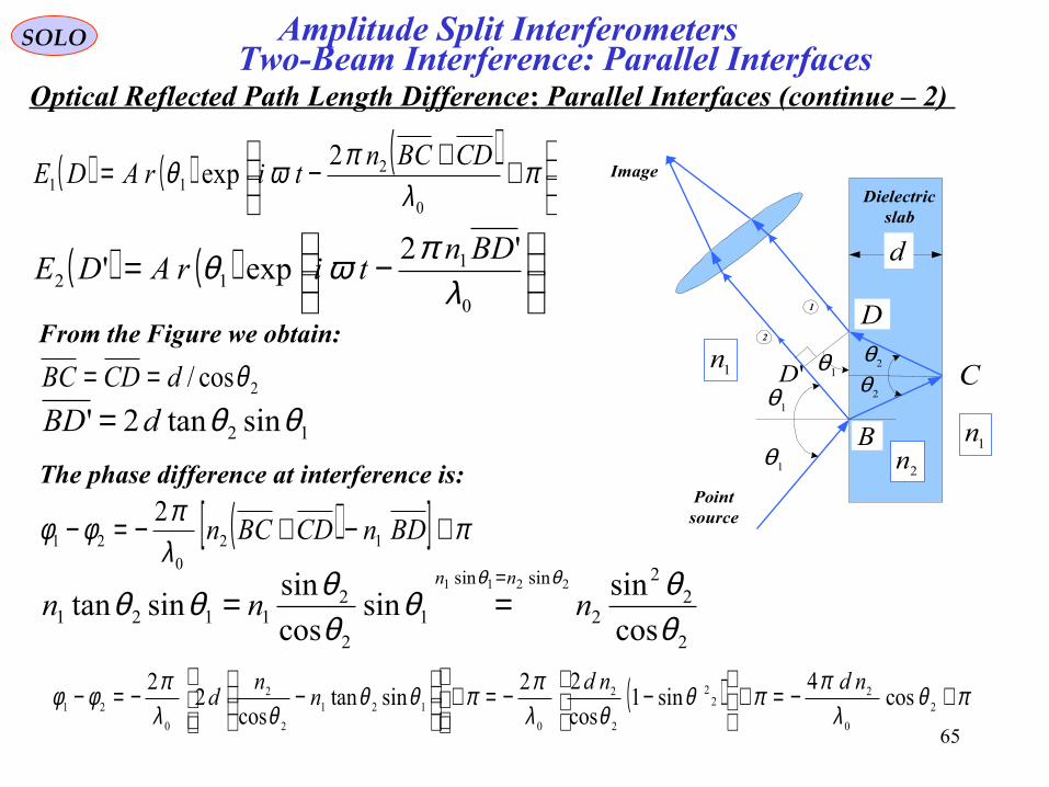
Optical Reflected Path Length Difference: Parallel Interfaces (continue – 2) Two-Beam Interference: Parallel Interfaces
'D1θ
1θ
1θ 2θ2θ
d
C
B
D
1n
2n1n
Pointsource
Image
1
2
Dielectricslab
( ) ( )
−=
0
112
'2exp'
λπωθ BDn
tirADE
( ) ( ) ( )
++−= π
λπωθ
0
211
2exp
CDBCntirADE
2cos/ θdCDBC ==From the Figure we obtain:
12 sintan2' θθdBD =The phase difference at interference is:
( )[ ] πλπφφ +−+−=− BDnCDBCn 120
21
2
2
22
2
sinsin
12
21121 cos
sinsin
cos
sinsintan
2211
θθθ
θθθθ
θθnnn
nn =
==
( ) πθλ
ππθθλ
ππθθθλ
πφφ +−=+
−−=+
−−=− 2
0
222
2
2
0
121
2
2
0
21 cos4
sin1cos
22sintan
cos2
2 ndndn
nd
Amplitude Split Interferometers
66
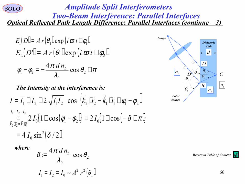
SOLO
Optical Reflected Path Length Difference: Parallel Interfaces (continue – 3) Two-Beam Interference: Parallel Interfaces
'D1θ
1θ
1θ 2θ2θ
d
C
B
D
1n
2n1n
Pointsource
Image
1
2
Dielectricslab
( ) ( ) ( )212 exp' φωθ += tirADE
( ) ( ) ( )111 exp φωθ += tirADE
πθλ
πφφ +−=− 20
221 cos
4 nd
The Intensity at the interference is:
( )( ){ } ( ){ }
( )2/sin4
cos12cos12
cos2
20
0210
2111222121
021
122
δ
πδφφ
φφ
I
II
rkrkIIIIIIII
rkrk
=
+−+=−+=
−+⋅−⋅++===
⋅=⋅
where
20
2 cos4
: θλ
πδ nd=
( )122021 ~ θrAIII ==
Amplitude Split Interferometers
Return to Table of Content
67
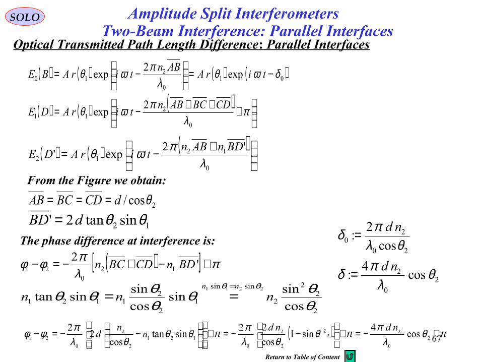
SOLO
Optical Transmitted Path Length Difference: Parallel InterfacesTwo-Beam Interference: Parallel Interfaces
Amplitude Split Interferometers
( ) ( ) ( )
+−=0
1212
'2exp'
λπωθ BDnABn
tirADE
( ) ( ) ( )
+++−= π
λπωθ
0
211
2exp
CDBCABntirADE
2cos/ θdCDBCAB ===From the Figure we obtain:
12 sintan2' θθdBD =The phase difference at interference is:
( )[ ] πλπφφ +−+−=− '2
120
21 BDnCDBCn
2
22
2
sinsin
12
21121 cos
sinsin
cos
sinsintan
2211
θθθ
θθθθ
θθnnn
nn =
==
( ) πθλ
ππθθλ
ππθθθλ
πφφ +−=+
−−=+
−−=− 2
0
222
2
2
0
121
2
2
0
21 cos4
sin1cos
22sintan
cos2
2 ndndn
nd
( ) ( ) ( ) ( )010
210 exp
2exp δωθ
λπωθ −=
−= tirA
ABntirABE
20
2
20
20
cos4
:
cos
2:
θλ
πδ
θλπδ
nd
nd
=
=
Return to Table of Content
68
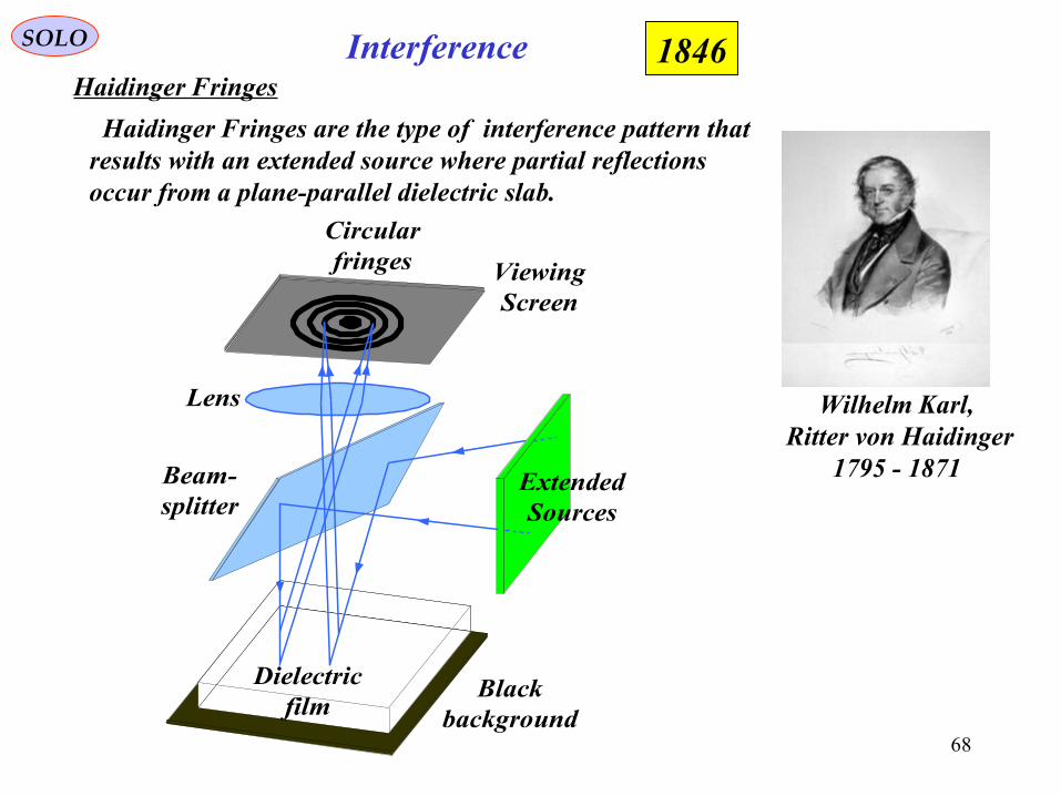
InterferenceSOLO
Haidinger Fringes1846
Wilhelm Karl, Ritter von Haidinger
1795 - 1871
Lens
Beam-splitter
ExtendedSources
ViewingScreen
Dielectricfilm
Blackbackground
Circularfringes
Haidinger Fringes are the type of interference pattern that results with an extended source where partial reflectionsoccur from a plane-parallel dielectric slab.
69
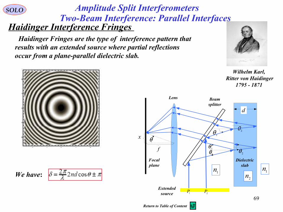
SOLO
Haidinger Interference Fringes Two-Beam Interference: Parallel Interfaces
We have:
1θ
1θ
2θ
2θ
d
1n2n
1n
Extendedsource
Focalplane
1P2P
1θ
Dielectricslab
Beamsplitter
Lens
θ
f
x
Haidinger Fringes are the type of interference pattern that results with an extended source where partial reflectionsoccur from a plane-parallel dielectric slab.
Wilhelm Karl, Ritter von Haidinger
1795 - 1871
Amplitude Split Interferometers
Return to Table of Content
70
InterferenceSOLO
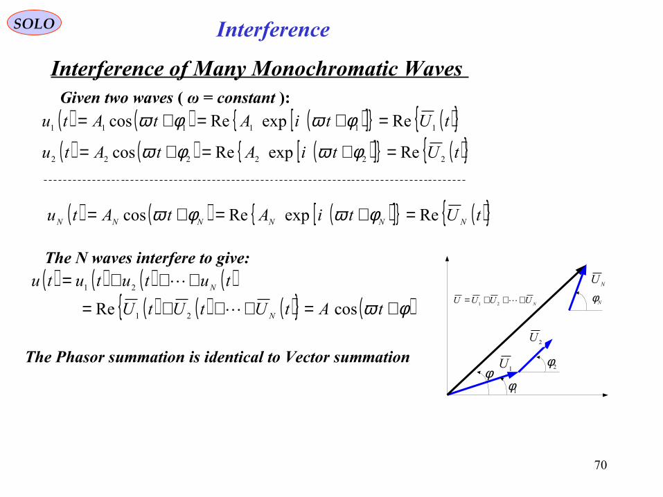
Interference of Many Monochromatic Waves Given two waves ( ω = constant ):
( ) ( ) ( )[ ]{ } ( ){ }tUtiAtAtu 111111 ReexpRecos =+=+= φωφω
The N waves interfere to give:( ) ( ) ( ) ( )
( ) ( ) ( ){ } ( )φω +=+++=
+++=
tAtUtUtU
tutututu
N
N
cosRe 21
21
( ) ( ) ( )[ ]{ } ( ){ }tUtiAtAtu 222222 ReexpRecos =+=+= φωφω
1U
NUUUU +++= 21
1φ
2φφ
2U
NU
Nφ
The Phasor summation is identical to Vector summation
( ) ( ) ( )[ ]{ } ( ){ }tUtiAtAtu NNNNNN ReexpRecos =+=+= φωφω
71
InterferenceSOLO
Multiple Beam Interference from a Parallel Film We have a point source and a dielectric slab that performs a multiple reflection and transmission.
72
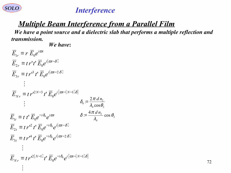
InterferenceSOLO
Multiple Beam Interference from a Parallel Film
( )
( )
( )[ ]
δω
δω
δω
ω
10
32
20
33
02
01
''
''
''
−−−
−
−
=
=
=
=
NtiNrN
tir
tir
tir
eEtrtE
eEtrtE
eEtrtE
eErE
We have:
We have a point source and a dielectric slab that performs a multiple reflection and transmission.
( )
( )
( ) ( )[ ]
δωδ
δωδ
δωδ
ωδ
10
12
20
43
02
2
01
0
0
0
0
''
''
''
'
−−−−
−−
−−
−
=
=
=
=
NtiiNrN
tiit
tiit
tiit
eeEtrtE
eeEtrtE
eeEtrtE
eeEttE 20
2
20
20
cos4
:
cos
2:
θλ
πδ
θλπδ
nd
nd
=
=
73
InterferenceSOLO
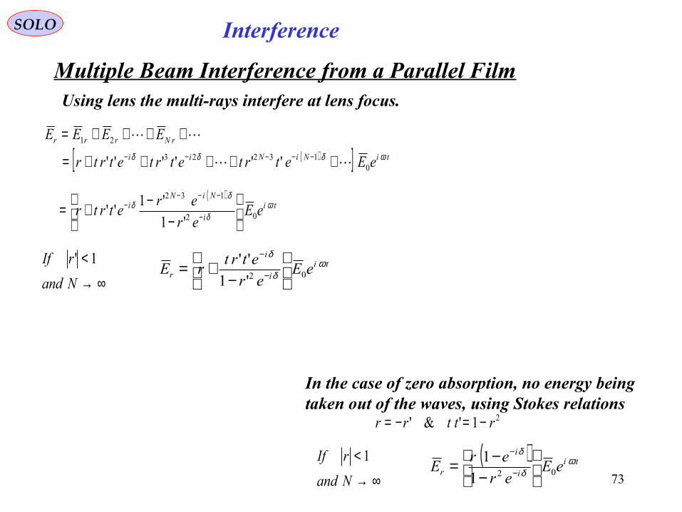
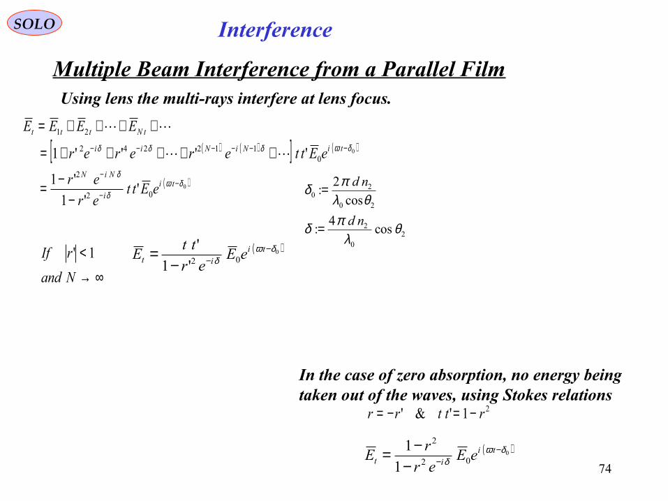
Multiple Beam Interference from a Parallel FilmUsing lens the multi-rays interfere at lens focus.
( )[ ] tiNiNii
rNrrr
eEetrtetrtetrtr
EEEEωδδδ
013223
21
''''''
+++++=
++++=−−−−−
( )ti
i
NiNi eE
er
eretrtr ω
δ
δδ
02
132
'1
'1''
−
−+= −
−−−−
∞→<
Nand
rIf 1' tii
i
r eEer
etrtrE ω
δ
δ
02'1
''
−
+= −
−
In the case of zero absorption, no energy being taken out of the waves, using Stokes relations
21'&' rttrr −=−=
( ) tii
i
r eEer
erE ω
δ
δ
021
1
−
−= −
−
∞→<
Nand
rIf 1
74
InterferenceSOLO
Multiple Beam Interference from a Parallel FilmUsing lens the multi-rays interfere at lens focus.
( ) ( )[ ] ( )00
112242
21
''''1 δωδδδ −−−−−− +++++=
++++=tiNiNii
tNttt
eEttererer
EEEE
( )002
2
''1
'1 δωδ
δ−
−
−
−−= ti
i
NiN
eEtter
er
∞→<
Nand
rIf 1' ( )002'1
' δωδ
−−−
= tiit eE
er
ttE
In the case of zero absorption, no energy being taken out of the waves, using Stokes relations
21'&' rttrr −=−=
( )002
2
1
1 δωδ
−−−
−= tiit eE
er
rE
20
2
20
20
cos4
:
cos
2:
θλ
πδ
θλπδ
nd
nd
=
=
75
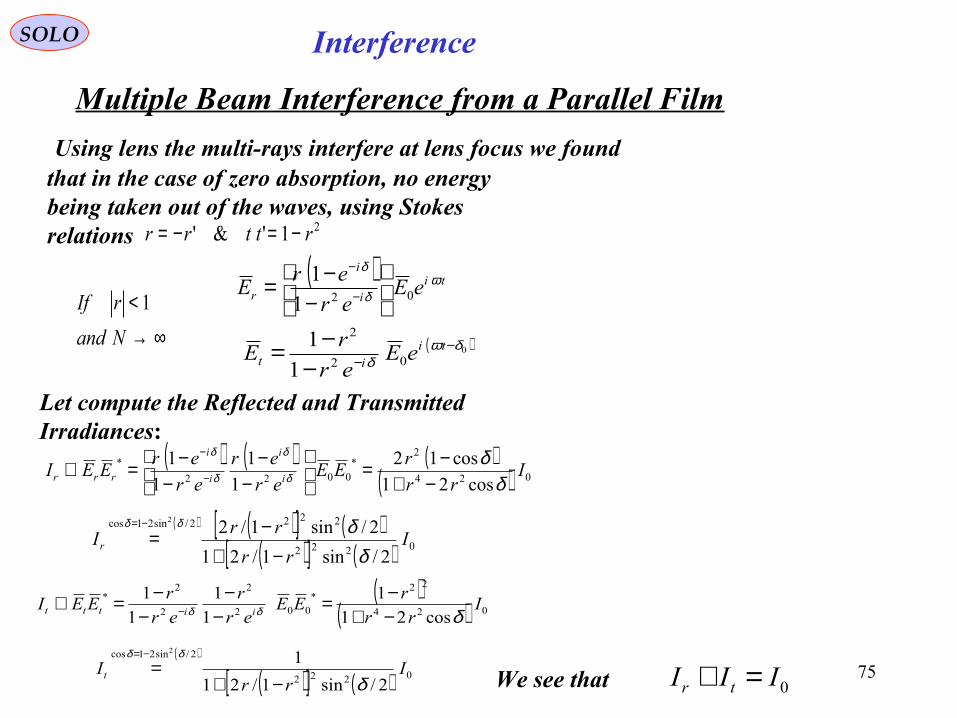
InterferenceSOLO
Multiple Beam Interference from a Parallel Film
∞→<
Nand
rIf 1( ) ti
i
i
r eEer
erE ω
δ
δ
021
1
−
−= −
−
( )002
2
1
1 δωδ
−−−
−= tiit eE
er
rE
Let compute the Reflected and Transmitted Irradiances:
( ) ( ) ( )( ) 024
2*
0022
*
cos21
cos12
1
1
1
1I
rr
rEE
er
er
er
erEEI
i
i
i
i
rrr δδ
δ
δ
δ
δ
−+−=
−
−−
−=∝ −
−
( )( ) 024
22*
002
2
2
2*
cos21
1
1
1
1
1I
rr
rEE
er
r
er
rEEI
iittt δδδ −+−=
−−
−−=∝ −
Using lens the multi-rays interfere at lens focus we foundthat in the case of zero absorption, no energy being taken out of the waves, using Stokes relations 21'&' rttrr −=−=
0III tr =+
( ) ( )[ ] ( )( )[ ] ( ) 0222
2222/sin21cos
2/sin1/21
2/sin1/22
Irr
rrIr
δδδδ
−+−=
−=
( )
( )[ ] ( ) 0222
2/sin21cos
2/sin1/21
12
Irr
Itδ
δδ
−+=
−=
We see that
76
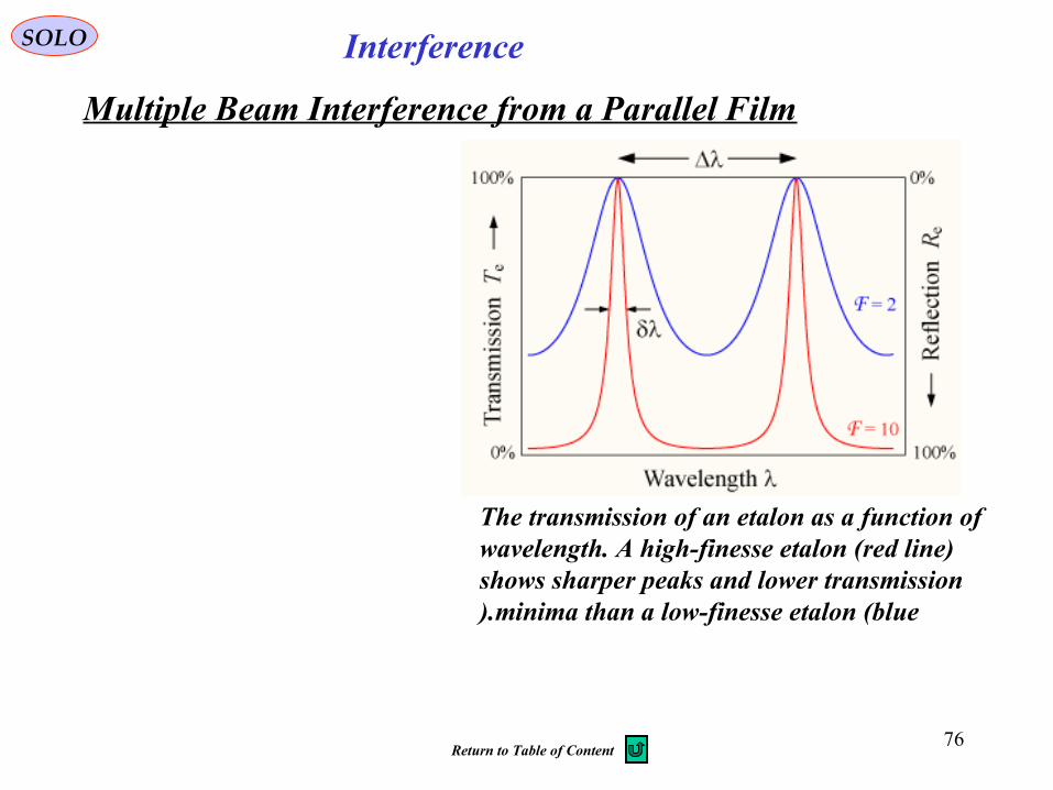
The transmission of an etalon as a function of wavelength. A high-finesse etalon (red line) shows sharper peaks and lower transmission
minima than a low-finesse etalon (blue).
InterferenceSOLO
Multiple Beam Interference from a Parallel Film
Return to Table of Content
77
Gas RefrectometerSOLO
S
1S
2S2T
1T
f
1C
2CD
D
1C 2C
E
Rayleigh's Interferometer
t
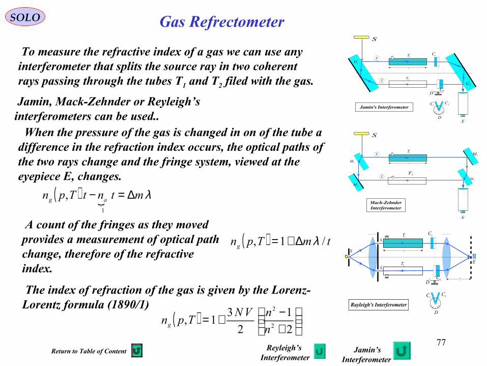
To measure the refractive index of a gas we can use any interferometer that splits the source ray in two coherent rays passing through the tubes T1 and T2 filed with the gas.
When the pressure of the gas is changed in on of the tube a difference in the refraction index occurs, the optical paths of the two rays change and the fringe system, viewed at the eyepiece E, changes.
A count of the fringes as they moved provides a measurement of optical path change, therefore of the refractive index.
Jamin, Mack-Zehnder or Reyleigh’s interferometers can be used..
S
2T
1T 1C
2CD
D
1C 2C
E
1G
2G
1
2
Jamin's Interferometer
t
S
1T
E
1M
2G
1
2
Mach-ZehnderInterferometer
2M
3M
4M2T
t
( ) λmtntTpn ag ∆=−1
,
( ) tmTpng /1, λ∆+=
The index of refraction of the gas is given by the Lorenz-Lorentz formula (1890/1)
( )
+−+=
2
1
2
31,
2
2
n
nVNTpng
Reyleigh’s Interferometer
Jamin’sInterferometer
Return to Table of Content
78
Interferometers HistorySOLOReferences
M.V.Klein, T.E. Furtak, “Optics”, 2nd Ed., John Wiley & Sons, 1986 , Ch. 5, Interference
M. Born, E. Wolf, “Principles of Optics”, Pergamon Press,6th Ed., 1980, Ch. VII,Elements of the Theory of Interference and Interferometers
S.G. Lipson, H. Lipson, “Optical Physics”, Cambridge University Press, 1969, Ch. 7,Fraunhofer Diffraction and Interference
E. Hecht, “Optics”, Addison Wesley, 2002, 4th Ed., Ch. 9, Interference
Françon, M., “Optical Interferometry”, Academic Press, 1966
M.V.Klein,“Optics”, 2nd Ed., John Wiley & Sons, 1970, Ch. 5, Interference
Steel, W.,H., “Interferometry”, Cambridge University Press, 1967
M. Kerker, “Scattering of Light and Other Electromagnetic Radiation”, Academic Press, 1969
J.C. Wyant, “Introduction to Interferometric Optical Testing (SC213)”, Optical Science Center, University of Arizona, http://www.optics.arizona.edu/jcwyant/
Return to Table of Content
January 5, 2015 79
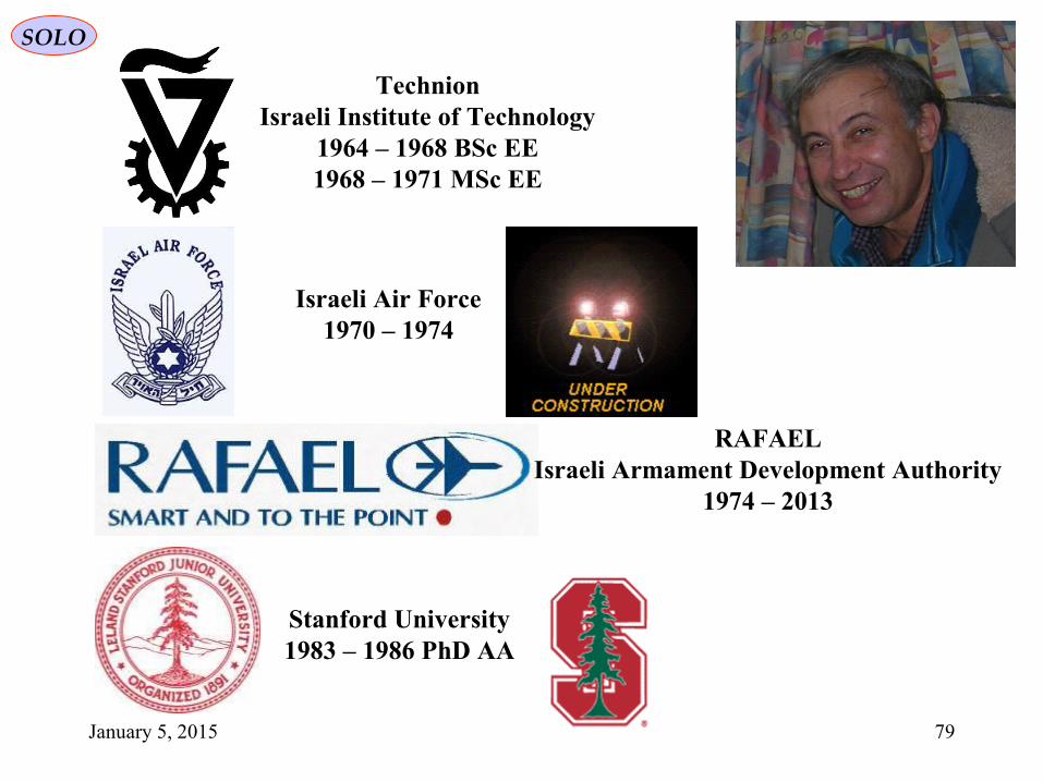
SOLO
TechnionIsraeli Institute of Technology
1964 – 1968 BSc EE1968 – 1971 MSc EE
Israeli Air Force1970 – 1974
RAFAELIsraeli Armament Development Authority
1974 – 2013
Stanford University1983 – 1986 PhD AA
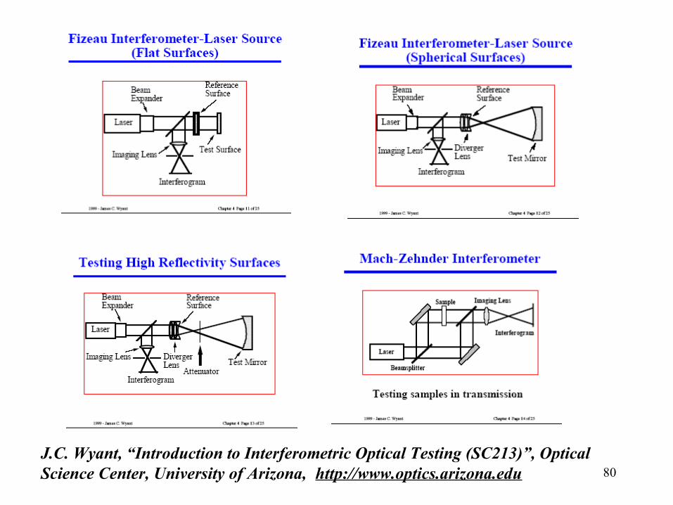
80J.C. Wyant, “Introduction to Interferometric Optical Testing (SC213)”, Optical Science Center, University of Arizona, http://www.optics.arizona.edu
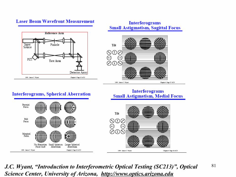
81J.C. Wyant, “Introduction to Interferometric Optical Testing (SC213)”, Optical Science Center, University of Arizona, http://www.optics.arizona.edu
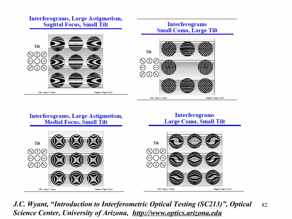
82J.C. Wyant, “Introduction to Interferometric Optical Testing (SC213)”, Optical Science Center, University of Arizona, http://www.optics.arizona.edu
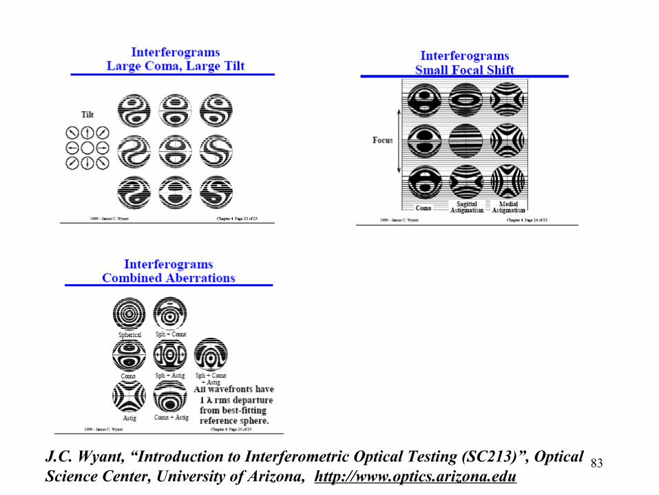
83J.C. Wyant, “Introduction to Interferometric Optical Testing (SC213)”, Optical Science Center, University of Arizona, http://www.optics.arizona.edu
84
85
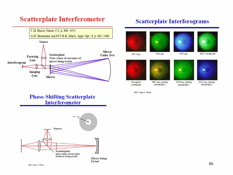
86
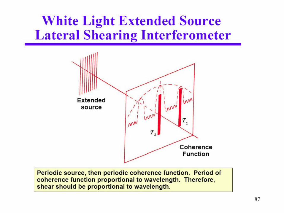
87
88
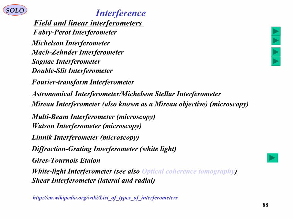
Field and linear interferometers InterferenceSOLO
Double-Slit Interferometer
Fourier-transform Interferometer
Astronomical Interferometer/Michelson Stellar Interferometer
Mireau Interferometer (also known as a Mireau objective) (microscopy)
Multi-Beam Interferometer (microscopy) Watson Interferometer (microscopy)
Linnik Interferometer (microscopy)
Diffraction-Grating Interferometer (white light)
White-light Interferometer (see also Optical coherence tomography) Shear Interferometer (lateral and radial)
http://en.wikipedia.org/wiki/List_of_types_of_interferometers
Michelson InterferometerMach-Zehnder Interferometer
Fabry-Perot Interferometer
Sagnac Interferometer
Gires-Tournois Etalon
89
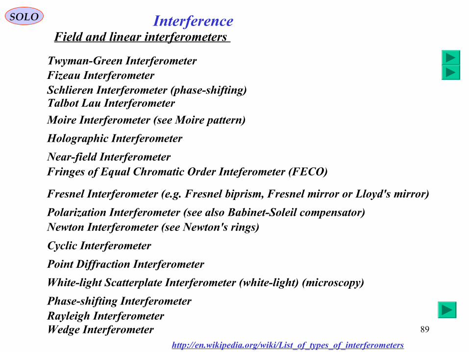
Field and linear interferometers InterferenceSOLO
Moire Interferometer (see Moire pattern)
Holographic Interferometer
Near-field InterferometerFringes of Equal Chromatic Order Inteferometer (FECO)
Fresnel Interferometer (e.g. Fresnel biprism, Fresnel mirror or Lloyd's mirror)
Polarization Interferometer (see also Babinet-Soleil compensator) Newton Interferometer (see Newton's rings)
Cyclic Interferometer
Point Diffraction Interferometer
White-light Scatterplate Interferometer (white-light) (microscopy)
Phase-shifting Interferometer
Wedge Interferometer
Schlieren Interferometer (phase-shifting) Talbot Lau Interferometer
http://en.wikipedia.org/wiki/List_of_types_of_interferometers
Fizeau Interferometer
Rayleigh Interferometer
Twyman-Green Interferometer
90
Intensity and nonlinear interferometers
InterferenceSOLO
http://en.wikipedia.org/wiki/List_of_types_of_interferometers
Intensity Interferometer
Intensity Optical CorrelatorFrequency-Resolved Optical Gating (FROG)
Spectral Phase Interferometry for Direct Electric-field Reconstruction (SPIDER)
Quantum optics interferometers Hong-Ou-Mandel Interferometer (HOM) (see Leonard Mandel)
Interferometers outside optics
Francon Interferometer
Atom InterferometerRamsey InterferometerMini Grail Interferometer
Hanbury-Brown Twiss Interferometer
91
http://www.grahamoptical.com/phase.html
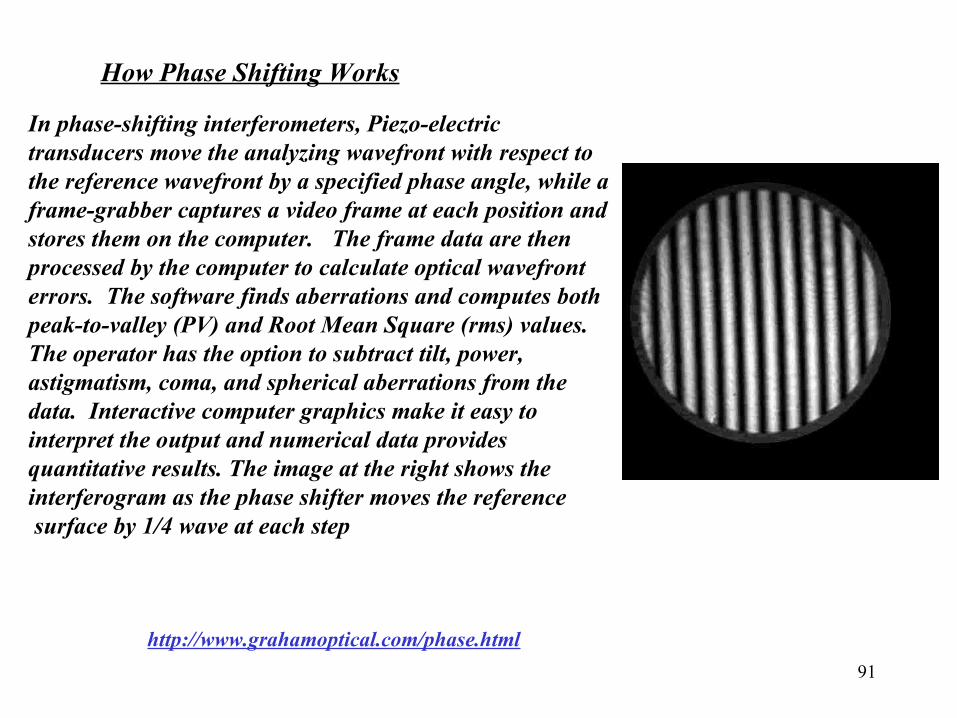
In phase-shifting interferometers, Piezo-electric transducers move the analyzing wavefront with respect to the reference wavefront by a specified phase angle, while a frame-grabber captures a video frame at each position and stores them on the computer. The frame data are then processed by the computer to calculate optical wavefront errors. The software finds aberrations and computes both peak-to-valley (PV) and Root Mean Square (rms) values. The operator has the option to subtract tilt, power, astigmatism, coma, and spherical aberrations from the data. Interactive computer graphics make it easy to interpret the output and numerical data provides quantitative results. The image at the right shows the interferogram as the phase shifter moves the reference surface by 1/4 wave at each step
How Phase Shifting Works
92
http://www.grahamoptical.com/phase.html
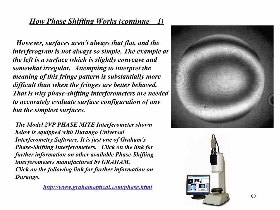
How Phase Shifting Works (continue – 1)
However, surfaces aren't always that flat, and the interferogram is not always so simple, The example at the left is a surface which is slightly convcave and somewhat irregular. Attempting to interpret the meaning of this fringe pattern is substantially more difficult than when the fringes are better behaved. That is why phase-shifting interferometers are needed to accurately evaluate surface configuration of any but the simplest surfaces.
The Model 2VP PHASE MITE Interferometer shown below is equipped with Durango Universal Interferometry Software. It is just one of Graham's Phase-Shifting Interferometers. Click on the link for further information on other available Phase-Shifting interferometers manufactured by GRAHAM. Click on the following link for further information on Durango.
93