interconnection of distributed energy resources · procedure for advanced ... use screens to speed...
TRANSCRIPT

Interconnection of Distributed Energy Resources
Emerson Reiter
NREL/PR-7A40-68595
April 19, 2017

2
• Understand the relationships between different aspects of interconnection
• Discuss best practices and lessons from US states and utility territories
• Provide an update on technical advances and standards for interconnection
Goals for this Session

Motivations

4
Solar Energy: Cost
Source: Tracking the Sun IX: The Installed Price of Residential and Non-Residential Photovoltaic Systems in the United States

5
Type of system determined by local solar resource
M
Solar Energy: Resources

6
Solar Energy: Utility Experiences of 10x Growth
0
100
200
300
400
500
Jan-13 Jan-14 Jan-15 Jan-16
Net
Met
ered
PV
inst
alla
tions
Empire District Electric Co (MO)
0
500
1000
1500
2000
2500
3000
Jan-13 Jan-14 Jan-15 Jan-16
Net
Met
ered
PV
inst
alla
tions
Modesto Irrigation District (CA)
0
5000
10000
15000
20000
Jan-13 Jan-14 Jan-15 Jan-16
Net
Met
ered
PV
inst
alla
tions
Nevada Power Co (NV)
Story: Strong rebates, implemented in May 2015, push solar into wide viability.
Story: Growing economic viability overcomes decline in state incentives to drive steady growth.
Story: Solar reaches economic “tipping point” in late 2014, attracting scale from national installers. Pre-Dec 2015 installs were granted grandfathering.

7
Solar Energy: TVPPA Context
Utility Name Total Customers
Additional DG systems/mo for 10x growth over 3 yrs
Nashville Electric Service 378,117 62 Johnson City - (TN) 77,025 18 Southwest Tennessee E M C 49,589 5 Joe Wheeler Elec Member Corp 42,812 2 Gibson Electric Members Corp 34,436 5 Fort Loudoun Electric Coop 31,571 8 Decatur Utilities 26,492 1 City of Newport 21,497 6 Tennessee Valley Electric Coop 19,442 2 Tri-State Electric Member Corp 18,475 12 City of Rockwood - (TN) 14,566 2 City of Hopkinsville 12,874 1 Bolivar Energy Authority 11,058 1 Forked Deer Electric Coop, Inc 9,871 1 McMinnville Electric System 8,002 0 Guntersville Electric Board 6,331 1

Intro to the Interconnection Process

9
• Outward-facing, customer service activity • Technical assessment by the utility • Internal business process for utility • Coordination effort with local AHJ
What is the Interconnection Process?

10
Who does what?
Installer
AHJ
Utility

11
What are the utility’s typical responsibilities?
Utility

Standards, Codes, and Interconnection Requirements

13
Standards & Codes are Foundational
Installer
AHJ
Utility
Standards and codes affect what is submitted to the AHJ and utility

14
Interconnection Codes & Standards

15
• Often used as Utility Manual of Safe Practices
• Covers basic provisions for safeguarding persons from hazards arising from installation, operation, and maintenance of conductors
• Typically applies to utilities and industrial users under the control of qualified persons
• Note: Section 444 of the NESC details “De-energizing equipment of lines to protect employees”
NESC – Minimizing Contact Risks

16
• Service Voltage – voltage at the point of delivery
• Range A (114-126V) is favorable, Range B (110-127V) is tolerable
ANSI C84.1

17
IEEE 1547™ (under full review/revision)
• Provides a uniform standard for interconnection of DR with EPS
• Set of standards govern performance, operation, testing, and safety

18
National Electrical Code (NEC)
National Fire Protection Association (NFPA) 70
• Adopted as law in most U.S. states, other areas
• Applies to Residential, Commercial, and Industrial facilities
• Often used in utility power plants, service centers
• Articles 690 (PV systems) & 705 (Interconnected Electric Power Production Sources)
• New Article 691 in next code cycle (Utility-Scale PV)

19
UL 1741
Inverters, Converters, Controllers, and Interconnection System Equipment for Use with Distributed Energy Resources
• Adopted as Legal Requirement in most U.S. states • Applies to the inverter and interconnection equipment • Inverters should be “listed” to this standard • Harmonized with IEEE 1547 • Underwriters Laboratories – Standard for Safety • UL 1741 has been updated for “Smart Inverter Use”
• UL 1741 Supplement A (SA)

20
Dependencies in Technical Standards
Prior to Supplement A, UL 1741 did not have a testing
procedure for advanced inverters
Without a developed testing program under UL 1741,
advanced inverters could not achieve UL listing
Installations using advanced inverters which are not UL-
listed cannot comply with the National Electrical Code
Installations which do not comply with the National Electrical Code will violate
state or local building codes
IEEE 1547-2003 does not allow inverters to perform "advanced" functions beyond those in IEEE
1547a-2014
In most states, an inverter which violates IEEE 1547-2003 does not
meet state interconnection standards
Inverter deployments which do not meet state standards will not pass utility interconnection processes
Equipment Safety Interconnection Performance

Technical Screens

22
Technical Screens are Key to Application Review
Installer
AHJ
Utility

23
Generic Utility Interconnection Review Process

24
Fast Track Screens (from FERC SGIP)
1. Aggregated DG <15% of peak load on line section (Penetration Screen)
2. For connection to a spot network: DG is inverter-based, aggregated DG capacity is <5% of peak load & <50 kW
3. Aggregated DG contribution to maximum short circuit current is <10%
4. Aggregated DG does not cause protective device to exceed 87.5% of short circuit interrupting capability
5. DG interface is compatible with type of primary distribution line (Wye/Delta)
6. For a single-phase shared secondary, aggregated DG capacity <20kW
7. Resulting imbalance <20% of service transformer rating of 240 V service
8. Aggregated transmission connected DG capacity <10 MW for stability-limited area
9. Construction not required for interconnection

25
Supplemental Review May Occur if Fast-Track not Achieved

26
• Evaluate transformer serving customer (Is it sufficient, can it be easily changed)
• Evaluate secondary lines serving customer
• Consider location of proposed PV to substation (short distance, large conductors, etc.)
• If Penetration Screen failed, consider other metrics such as 100% of minimum daytime load on line section (recommended by FERC)
Supplemental Screen Examples

27
Tension in Screening Process

Interconnection Studies and Mitigations

29
Detailed Studies Can Occur in Application Review
Installer
AHJ
Utility
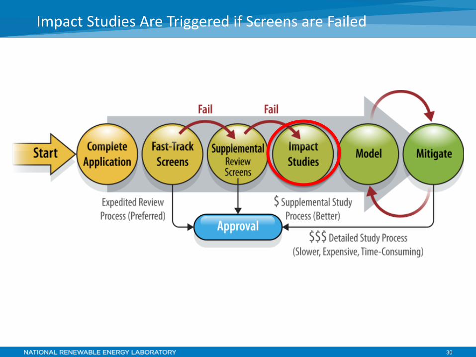
30
Impact Studies Are Triggered if Screens are Failed

31
21 Utility Survey (SGIP Focused)
PG&E SCE SDG&E SMUD
NSP Com Ed Detroit Edison Nashville Electric
PSCO PNM APS Tri County Electric Coop Austin Power SPS
NSTAR National Grid Con Ed O&R Central Hudson LIPA PEPCO

32
Major Utility Concerns
Voltage Regulation 76% Reverse power flow 52% Protection system coordination 48% Increased duty of line regulation equipment 38% Unintentional islanding 38% Secondary network protection 29% Variability due to clouds 24% Increased switching of capacitors 19%

33
Voltage Regulation – No PV

34
Voltage Regulation – w/ PV

35
Voltage Regulation – w/ PV

36
Most utilities employ one or more of the following;
• Power Flow (common) • Short Circuit (common) • Voltage (common)
• Feasibility • Facility • Flicker • Power Quality
• Dynamic/Transient Stability • Electromagnetic Transient
Detailed Impact Study Types
Most Commonly used Distribution Software
• SynerGi • CymDist • Milsoft Windmil • ASPEN

37
Mitigation Tools Available
Tools in the “Toolbox” • Upgrade Line Section • Modify Protection Scheme (breakers & fuses) • Voltage Regulation Devices (Add or chance control) • Direct Transfer Trip • Advanced Inverters Required • Communication & Control Technologies • Power Factor Controls (Often advanced inverters) • Grounding Transformers • Static VAR Compensators • Capacitor Control Modifications • Volt/VAR Controls

Interconnection as Business Process

39
1. Be clear 2. Be quick
How Can a Utility Improve Customer Service?

40
1. Be Clear
Installer
AHJ
Utility
Provide easily accessible guidance based on accepted standards
Have a designated point of contact for questions
Consolidate submission of applications to single channel (electronic)
Provide a way to track progress and/or maintain clear communication

41
Be clear o Easily accessible interconnection guidelines based on accepted standards
– Model procedures: FERC Small Generator Interconnection Procedure (SGIP), IREC
o Designated points of contact at utilities – Ideally, a real person, not a generic inbox
o Single channel for submission of application materials (electronic) – Eliminates coordination of mail, fax, e-mail applications
o Provide a way for installers to track progress and/or clear communication of decisions, timelines, and cost
– Email templates of standard updates
How Can a Utility Improve Customer Service?

42
2. Be Quick
Utility
Resolve application completeness quickly
Consider fast-track process (e.g. inverter-based, under 10 kW)
Process PTO paperwork quickly, last touch-point in the process
Use screens to speed processing, reduce burden on staff

43
Be clear o Easily accessible interconnection guidelines based on accepted standards o Designated points of contact at utilities o Single channel for submission of application materials (electronic) o Provide a way for installers to track progress and/or clear communication of
decisions, timelines, and cost Be quick
o Use checks for completeness – Engaging installers quickly can avoid long, frustrating waits
o Fast-track process (e.g. inverter-based systems under 10 kW) – Included in FERC SGIP and IREC model procedures
o Use screens to analyze systems quickly, reduce analytical burden on staff o Move paperwork quickly and efficiently
– Permission to Operate is simply confirming documents received and in order, last touch-point with customer in the process
o Bonus points: coordinate with local permitting process
How Can a Utility Improve Customer Service?

44
Municipal utilities may have unique opportunities to streamline the interconnection, incentive and building permit approval process as a result of having one centralized authority in control of the processes
Reducing Time and Cost of Interconnection

45
Municipalities Can Merge Permitting and Interconnection
Installer
AHJ
Utility
One application, same-day in-person review and approval

Advanced or “Smart” Inverters

47
Function Description Connect/disconnect Electrically connects to or disconnects from the grid Maximum generation limit Constrains real power output Volt-VAR function Adjusts reactive power output based on service voltage Volt-Watt function Adjusts real power output based on service voltage Frequency-Watt function Adjusts real power output based on service frequency Low/high frequency ride-through Defines frequency range for which inverter remains on-line Low/high voltage ride-through Defines voltage range for which inverter remains on-line Event/history logging Log and report standardized set of events Status reporting Report current device status
What is a “Smart” Inverter - Functions
Multiple efforts have been made to standardized function set for smart inverters Key capabilities include (but not limited to):
For More: EPRI, Common Functions for Smart Inverters, Version 3, Report # 3002002233 http://www.epri.com/abstracts/Pages/ProductAbstract.aspx?ProductId=000000003002002233 Distributed Energy Management (DER): Advanced Power System Management Functions and Information Exchanges for Inverter-based DER Devices, Modelled in IEC 61850-90-7 http://xanthus-consulting.com/Publications/documents/Advanced_Functions_for_DER_Inverters_Modeled_in_IEC_61850-90-7.pdf

48
• Increased grid stability o Local – voltage control from volt-VAR and volt-Watt functions o System – greater resiliency during frequency deviations
• Increased visibility into distribution system conditions via data collection
• Potential to defer investments in other distribution system hardware
What is a “Smart” Inverter - Benefits

49
Key Standards for Advanced Inverters • UL 1741
o Developed by Underwriter’s Laboratory (UL) o Primarily an equipment safety standard o Sets design requirements and testing procedures
• IEEE 1547 o Developed by Institute of Electrical and Electronics
Engineers (IEEE) o Primarily an interconnection performance standard o Governs how inverters affect electrical conditions at the
point of common coupling (PCC) with the grid
Key Barrier – Technical Standards

50
Standards acted as a barrier because other regulations rely on these measures
Key Barriers – Technical Standards
Prior to Supplement A, UL 1741 did not have a testing procedure for advanced inverters
Without a developed testing program under UL 1741, advanced inverters could not achieve
UL listing
Installations using advanced inverters which are not UL-listed cannot comply with the
National Electrical Code
Installations which do not comply with the National Electrical Code will violate
state or local building codes
IEEE 1547-2003 does not allow inverters to perform "advanced" functions beyond those in
IEEE 1547a-2014
In most states, an inverter which violates IEEE 1547-2003 does not meet
state interconnection standards
Inverter deployments which do not meet state standards will not pass
utility interconnection processes
Equipment Safety Interconnection Performance

51
Updated to include advanced functions Approved September 2016 Several inverters have been certified to date
UL 1741 Supplement A (UL 1741 SA)

52
Complete overhaul of interconnection requirements New content on: • Reactive power • Ride-through requirements • DER on secondary networks • Interoperability and communications • Test and verification requirements In balloting now, publication anticipated summer 2017
IEEE 1547 full revision

53
Communications bring challenges and benefits Challenges • Many layers of physical and software infrastructure • Standardization to maximize value requires coordination
across many parties Benefits • Enables certain high-value functions
o E.g. real power curtailment • Supports more frequent updates to otherwise-
autonomous functions • Increases visibility for distribution management
Key Barriers - Communications

54
Communications Level Inverter Functions Proceedings and Standards
Autonomous
– No communications architecture needed – Behavior controlled by operating parameters – Parameters defined at system commissioning – Parameters can be adjusted, behavior activated or deactivated at later date via remote or on-site changes
Low- / High-voltage ridethrough SIWG Phase 1
IEEE 1547a-2014
Low- / High-frequency ridethrough Volt-var control Anti-islanding
Ramp-rate controls Provide reactive power (via fixed power factor) Reconnect via “soft-start” Frequency-watt SIWG
Phase 3 Voltage-watt Dynamic current support Smooth frequency deviations
Non-Autonomous
– Communications and control infrastructure required – Direct control of inverter behavior – Control from remote operator commands or feedback, based on conditions at point of common coupling
Command DER to connect/disconnect SIWG Phase 3
Limit real power Set real power Provide black-start capability Respond to real power pricing signals Participate in automatic generator control (AGC) Provide spinning reserves or bid into market Update static set points for autonomous functions (fixed power factor, volt-var curves, voltage ride-through, frequency ride-through)
Key Barriers - Communications
Adapted from: http://www.pjm.com/~/media/committees-groups/committees/pc/20140428-advance/20140428-item-04-sma-smart-inverter-grid-support-capabilities.ashx
55
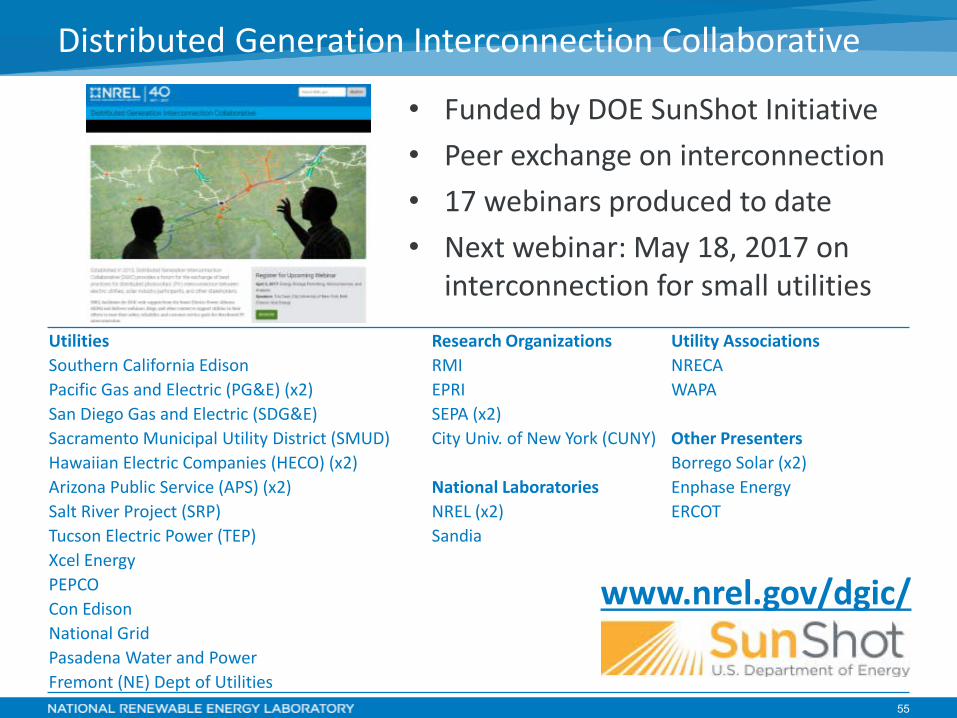
• Funded by DOE SunShot Initiative • Peer exchange on interconnection • 17 webinars produced to date • Next webinar: May 18, 2017 on
interconnection for small utilities
Distributed Generation Interconnection Collaborative
Utilities Research Organizations Utility Associations Southern California Edison RMI NRECA Pacific Gas and Electric (PG&E) (x2) EPRI WAPA San Diego Gas and Electric (SDG&E) SEPA (x2) Sacramento Municipal Utility District (SMUD) City Univ. of New York (CUNY) Other Presenters Hawaiian Electric Companies (HECO) (x2) Borrego Solar (x2) Arizona Public Service (APS) (x2) National Laboratories Enphase Energy Salt River Project (SRP) NREL (x2) ERCOT Tucson Electric Power (TEP) Sandia Xcel Energy PEPCO Con Edison National Grid Pasadena Water and Power Fremont (NE) Dept of Utilities
www.nrel.gov/dgic/

Thank You! Emerson Reiter [email protected] www.nrel.gov/dgic/