inter-system authentication mechanisms for seamless...
TRANSCRIPT

INTER-SYSTEM AUTHENTICATION MECHANISMS FOR SEAMLESS ROAMING
IN WIRELESS ENVIRONMENTS
By
AARTI BHARATHAN
A THESIS PRESENTED TO THE GRADUATE SCHOOL OF THE UNIVERSITY OF FLORIDA IN PARTIAL FULFILLMENT
OF THE REQUIREMENTS FOR THE DEGREE OF MASTER OF SCIENCE
UNIVERSITY OF FLORIDA
2003

Copyright 2003
by
Aarti Bharathan

This document is dedicated to the graduate students of the University of Florida.

ACKNOWLEDGMENTS
I would like to thank my advisor Dr. Janise McNair for her trust and faith in me,
and for constantly inspiring me. Her constant encouragement and enthusiasm for my
work resulted in the successful completion of my thesis.
I would also like to thank Dr. Haniph Latchman, and Dr. Richard Newman for
serving on my supervisory committee.
Finally, I would like to thank my best friend and constant supporter and new
husband Nikhil George for his constant support, advice and interest in my work. I would
also like my friends Srivatsan Madhavan and Nebojsa Ciric for their help throughout my
master’s. And finally, I thank my parents and my sister Archana, for always being on my
side, come what may.
iv

TABLE OF CONTENTS Page ACKNOWLEDGMENTS ................................................................................................. iv
LIST OF TABLES........................................................................................................... viii
LIST OF FIGURES ........................................................................................................... ix
ABSTRACT....................................................................................................................... xi
CHAPTERS
1 INTRODUCTION ............................................................................................................1
2 BACKGROUND ..............................................................................................................5
2.1 Encryption and Cryptography.................................................................................7 2.1.1 Symmetric Key Cryptography......................................................................8 2.1.2 Public Key Cryptography ...........................................................................10
2.1.2.1 RSA ..................................................................................................11 2.1.2.2 RSA key generation .........................................................................12 2.1.2.3 RSA encryption ................................................................................12 2.1.2.4 RSA decryption ................................................................................13
2.2 Authentication.......................................................................................................14 2.2.1 Authentication, Authorization and Accounting Architecture.....................14 2.2.2 Authenticators.............................................................................................16
2.2.2.1 Message encryption..........................................................................16 2.2.2.2 Message authentication codes ..........................................................18 2.2.2.3 Hash functions..................................................................................18
2.2.3 Authentication Protocols ............................................................................19 2.2.3.1 Password authentication protocol.....................................................19 2.2.3.2 Challenge authentication handshake protocol (CHAP) ...................20
2.2.4 Two Authentication Systems......................................................................21 2.2.4.1 Kerberos – a symmetric key authentication service.........................21 2.2.4.2 X.509 – a public key authentication system.....................................24
2.2.5 Inter-Domain Authentication......................................................................26
3 CELLULAR NETWORK AUTHENTICATION STANDARDS .................................28
3.1 GSM Security and Authentication........................................................................28
v

3.1.1 GSM Architecture ......................................................................................29 3.1.2 GSM Authentication...................................................................................31 3.1.3 2G GSM Security Weaknesses...................................................................33
3.2 UMTS Security and Authentication .....................................................................34 3.2.1 UMTS Architecture ....................................................................................34
3.2.1.1 User equipment (UE) .......................................................................35 3.2.1.2 The core network (CN) ....................................................................35
3.2.2 3G Security Principles................................................................................36 3.2.2.1 Network access security ...................................................................37 3.2.2.2 Network domain security .................................................................39 3.2.2.3 User domain security........................................................................40 3.2.2.4 Application security .........................................................................40
4 WIRELESS LOCAL AREA NETWORK AND INTERNET AUTHENTICATION STANDARDS ............................................................................................................42
4.1 802.11 WEP Protocol ...........................................................................................43 4.1.1 WEP Encryption and Decryption ...............................................................43 4.1.2 WEP Authentication...................................................................................44 4.1.3 Problems with WEP ...................................................................................46
4.2 Internet Authentication .........................................................................................47 4.2.1 RADIUS .....................................................................................................48 4.2.2 Diameter .....................................................................................................48
4.3 Mobile IP ..............................................................................................................50 4.3.1 Mobile IP with AAA ..................................................................................51 4.3.2 Various Mobile IP scenarios for AAA servers...........................................53 4.3.3 Protocol Flow Control ................................................................................54
5 VISA: AN ADVANCED INTER-SYSTEM AUTHENTICATION PROTOCOL........58
5.1 AdVanced Inter-System Authentication Architecture..........................................60 5.2 Mobile Node Passport...........................................................................................61 5.3 Mobile Node Visa.................................................................................................65 5.4 Obtaining a Mobile Node Passport and a Mobile Node Visa...............................67 5.5 Entering a Foreign System....................................................................................70
5.5.1 Full Handshake...........................................................................................71 5.5.2 Abbreviated Handshake..............................................................................73 5.5.3 Refreshing the Passport and Visa Keys......................................................74
6 IMPLEMENTATION AND SIMULATION OF VISA.................................................76
6.1 Java Implementation.............................................................................................76 6.1.1 Java Security...............................................................................................77 6.1.2 Network Signaling Mechanisms.................................................................78
vi

6.1.2.1 Mobile node – visa centre signaling architecture.............................78 6.1.2.2 J2SE, J2ME signaling constraints ....................................................79
6.1.3 Mobile Node Passport and Visa Implementation.......................................80 6.1.4 Visa Centre Implementation.......................................................................82
6.1.4.1 Handshake mechanisms ...................................................................83 6.1.4.2 Authentication mechanisms .............................................................83
6.1.5 Mobile Node Implementation.....................................................................84 6.2 OPNET Simulation...............................................................................................85
6.2.1 Simulation Architecture..............................................................................86 6.2.2 The Custom Application Model .................................................................88
6.3 Java Emulation Performance Results ...................................................................91 6.4 OPNET Simulation Performance Results.............................................................93
6.4.1 Analysis of VISA Handshake Mechanisms ...............................................93 6.4.1.1Analysis of full handshake ................................................................94 6.4.1.2 Abbreviated handshake analysis ......................................................99
6.4.2 Simulation Results....................................................................................101
7 CONCLUSIONS...........................................................................................................106
LIST OF REFERENCES.................................................................................................109
BIOGRAPHICAL SKETCH ...........................................................................................112
vii

LIST OF TABLES
Table page 6.1 Traffic Modeling in OPNET.......................................................................................89
6.2 Full Handshake ...........................................................................................................91
6.3 Abbreviated Handshake ..............................................................................................91
6.4 Full Handshake Application Statistics ........................................................................95
6.5 Wireless LAN Statistics (Full Handshake) .................................................................97
6.6 Wireless LAN Load (Full Handshake) .......................................................................98
6.7 Wireless LAN Statistics............................................................................................101
6.8 Comparison Chart for Traffic Sent ...........................................................................102
6.9 Comparison Chart for Traffic Received ...................................................................104
6.10 Comparison Chart for Network Load .....................................................................105
viii

LIST OF FIGURES
Figure page 1.1 3G – IMT2000 Scenario ...............................................................................................2
2.1 Attack Categories..........................................................................................................6
2.2 RC5 Encryption ............................................................................................................9
2.3 AAA Framework ........................................................................................................15
2.4 Overview of Kerberos Authentication Service ...........................................................22
2.5 X.509 Certificate Format ............................................................................................25
3.1 GSM Architecture.......................................................................................................29
3.2 GSM Authentication and Access Control...................................................................32
3.3 UMTS Architecture ....................................................................................................35
3.4 3GPP-UMTS Security Architecture ...........................................................................37
3.5 Authentication And Access Control in UMTS ...........................................................38
4.1 Wireless Local Area Network Architecture................................................................42
4.2 Shared – Key Authentication ......................................................................................46
4.3 Mobile IP Communication.........................................................................................51
4.4 Internet AAA Architecture for Mobile IP...................................................................52
4.5 AAA Architecture with Security Associations ...........................................................55
4.6 AAA Architecture with Security Associations during Registration Reply ................56
5.1 AdVanced Inter-System Authentication Architecture ................................................60
5.2 Structure of the Passport .............................................................................................63
5.3 Structure of the Mobile Node Visa .............................................................................66
ix

5.4 Request for Visa..........................................................................................................68
5.5 Visa Request PDU ......................................................................................................69
5.6 Visa Response PDU....................................................................................................70
5.7 Full Handshake ...........................................................................................................71
5.8 Abbreviated Handshake ..............................................................................................73
6.1 Passport in the Unified Modeling Language Notation ...............................................80
6.2 Visa in the Unified Modeling Language Notation......................................................81
6.3 Visa Centre in the Unified Modeling Language Notation ..........................................82
6.4 Authentication Module in the UML Notation ............................................................83
6.5 Mobile Node in the UML Notation ............................................................................84
6.6 Office Enterprise Topology ........................................................................................86
6.7 Office Building Subnet ...............................................................................................87
6.8 A Snapshot of the Network Monitor Results..............................................................92
6.9 Memory Monitor Results............................................................................................92
6.10 Function Call Graph..................................................................................................93
6.11 Application Traffic Received (Full Handshake).......................................................95
6.12 Application Traffic Sent (Full Handshake)...............................................................96
6.13 Wireless LAN Load (Full Handshake) .....................................................................97
6.14 WLAN Average Delay (Full Handshake).................................................................99
6.15 Abbreviated Handshake Data Sent and Received...................................................100
6.16 Average Network Load...........................................................................................100
6.17 Application Traffic Sent .........................................................................................102
6.18 Traffic Received......................................................................................................103
6.19 Average Network Load...........................................................................................104
x

Abstract of Thesis Presented to the Graduate School
of the University of Florida in Partial Fulfillment of the Requirements for the Degree of Master of Science
INTER-SYSTEM AUTHENTICATION MECHANISMS FOR SEAMLESS ROAMING IN WIRELESS ENVIRONMENTS
By
Aarti Bharathan
December, 2003
Chair: J. McNair Major Department: Electrical and Computer Engineering
In the last decade of the twentieth century, wireless communications was believed
to be heading toward a global wireless system, such as UMTS or IMT2000. In fact,
wireless communications is rapidly becoming a highly distributed collection of different
types of networks.
For example, an individual can obtain high bandwidth services through wireless
local area networks (WLANs), flexible ad hoc service through wireless personal area ad
hoc networks (WPANs), highly mobile voice and data services through wireless wide
area networks (WWANs), and Internet-based wireless service through Mobile IP. This
environment is desirable for users who wish to access multiple services from different
networks, depending on the desired quality of service. There is also a better utilization of
bandwidth. This results in networks collaborating not just with alien mobile terminals,
but also with the servers of other networks. However, allowing users to move between
xi

networks creates problems for security in that authentication becomes a distributed,
disconnected process.
In 2G and 3G cellular systems, the authentication of mobile users is accomplished
via a centralized authentication authority. However, a centralized approach is not suitable
for the distributed, multi-network environment. In this thesis, an adVanced Inter-System
Authentication (VISA) process is introduced to validate unknown users that have
established an account history with a previous network. First, a distributed multi-network
authentication architecture is proposed. Then, two new mechanisms, the mobile node
passport and mobile node visa, are introduced within a discussion of the proposed inter-
system authentication process. Finally, a performance analysis is provided, that
demonstrates the processing and network loads generated by the VISA protocol.
xii

CHAPTER 1 INTRODUCTION
At the end of the twentieth century, wireless and mobile communications
experienced a widespread commercial success that even now continues to exceed
expectations. The number of cellular subscribers has grown from the 10’s of millions of
users in the1990’s to 100’s of millions of users in the year 2000 to projections of 1 billion
wireless users by 2010 [1]. In the last decade of the twentieth century, wireless
communications was believed to be heading toward a global wireless system, such as
Universal Mobile Telecommunication System (UMTS) or International Mobile
Telecommunications – 2000 (IMT2000). In fact, wireless communications is rapidly
becoming a highly distributed collection of different types of networks. The various types
of networks include the following:
• Wireless wide area networks (WWANs) Third generation (3G) global wireless systems such as the UMTS and the IMT-2000 shown in figure 1.1 were designed to expand the second generation (2G) cellular service.
• Wireless local area networks (WLANs) Wi-Fi networks such as 802.11, that provide access to Ethernet technologies without the costly infrastructure of 3G.
• Satellite networks Space based networks such as Iridium and Globalstar that provide GPS location services, high bandwidth services and the ability to reach customers in rural areas. (Although Iridium declared bankruptcy in the year 2000, its satellite constellation is still in existence and is being used by the Department of Defense).
• High aeronautical altitude platforms (HAAPs) Aircraft that provide metropolitan areas with high bandwidth coverage without the costly infrastructure of a satellite network.
• Internet-based Wireless Services Mobile IP networks that allow users to change their location while maintaining Internet connectivity.
1

2
Figure 1.1 3G – IMT2000 Scenario
The advantage to these diverse networks is that they offer many choices for
increasing bandwidth options, providing access to the Internet, and increasing the
coverage area of the average user. This is desirable for users who wish to access multiple
services from different networks, depending on the desired quality of service. However,
allowing users to move between networks creates problems for security, in that
authentication becomes a distributed, disconnected process. Well-established
authentication-based systems, such as GSM-Mobile Application Part (GSM-MAP) or IS-
41, provide authentication services through a centralized authentication center, in
cooperation with home and visitor location registers. However, a diverse network
environment does not yield itself to a centralized authority, nor is there any existing
mechanism to enable networks to validate users that roam between different networks or
service providers.

3
For example, a company such as IBM may install WLAN services, so that
employees and visitors can have free mobility with access to the backbone network.
However, in the WLAN system, no authentication mechanism is in place. Thus, a
possible security breach has been created for the network in order to offer services to an
unauthenticated user. The company may choose to restrict access, e.g., to only in-
building use or to only a restricted group of users, but this technique reduces the
flexibility in network establishment and roaming options that make the WLAN an
attractive choice for an industrial environment.
Registration is the network management process that authenticates mobile users.
Traditionally, registration research is concerned with tracking the mobile user's current
location. However, this thesis does not address the user tracking and location update
problem, but focuses on the problem of authentication of unknown users. The current and
familiar research on location registration is based on a global cellular system, which has a
controlled, centralized authentication architecture. The multiple network (multi-network)
architecture does not have an existing mechanism to enable networks to validate users
that roam between different networks or service providers. Even among the global
cellular networks, such as GSM, a central authority in one network is of no use when the
user leaves to roam into the service area of a different network, e.g., IS-136.
In this thesis, an adVanced Inter-System Authentication (VISA) process is presented
to assist in the validation of unknown users who have an established account history with
a previous network. In Chapter 2, background on the problem is provided including a
discussion of security and authentication protocols. Chapter 3 and Chapter 4 describe
related work and standards activity for wireless authentication. Chapter 5 introduces the

4
VISA protocol, followed by a performance analysis in Chapter 6. Chapter 7 concludes
with a discussion on future work.

CHAPTER 2 BACKGROUND
Authentication involves the use of advanced security techniques to support the
exchange of user identity and account information. The requirements of information
security have undergone major changes since the inception of information technology. At
the earliest times, security was limited to computer security. Its main task was to secure
data and thwart attacks by hackers. With the advent of distributed systems, and the
emergence of various area networks for data communication among computers, network
security gained significant attention, particularly with respect to use of the Internet and
wireless technology. This chapter describes first the security techniques most often used
in authentication, such as cryptography and key exchange and then defines the problem
of authentication.
Any action that compromises data is a security attack. Security attacks may be
passive or active. A passive attack results in loss of privacy of data while an active attack,
results in the loss, modification or even fabrication of data. Figure 2.1 describes the
general attack categories. Figure 2.1a shows the normal flow of data from source to
destination without any attacks – passive or active. Figure 2.1b shows an attack on
availability, as an asset of the system is destroyed. This is similar to destroying a
communication link or file management system. Figure 2.1c describes an attack on
confidentiality, wherein a third party gains access to an asset. This is similar to
eavesdropping a conversation or viewing data packets over a network. Figure 2.1d shows
an attack on integrity, wherein an unauthorized party accesses and tampers with an asset.
5

6
(a) Normal Flow Information Source Information Destination (b) Interruption (c) Interception (d) Modification (e) Fabrication Figure 2.1 Attack Categories [2]
Finally, figure 2.1e describes an attack on authenticity, wherein a foreign party
inserts his own data into the system. This is similar to getting messages from an
unsolicited source in a secure network.
7
2.1 Encryption and Cryptography
One of the most important techniques for combating security attacks in computer
networks is the use of encryption and cryptography. Encryption is the transformation of a
piece of information into scrambled data that cannot be “understood” by anyone other
than the sender and the receiver. The initial information is referred to as plain-text, while
the encrypted data is code or cipher-text.
Cryptography is the art of protecting information by transforming it (encrypting it)
into an unreadable format, called cipher text. Only those who possess a secret key can
decipher (or decrypt) the message into plain text. A security key is typically a numeric
value independent of the content of the data to be encrypted, that is “worked” on the
given data to result in some piece of data that has no apparent relationship with the actual
data. Encrypted messages can sometimes be broken by cryptanalysis, also called
codebreaking, although modern cryptography techniques are virtually unbreakable.
There are three encryption and cryptography techniques used to protect computer
networking information: hash functions, symmetric key cryptography and public key
cryptography. A Hash Function generates a hash value (or simply hash) from a string of
text [2]. The hash is substantially smaller than the text itself, and is generated by a
formula in such a way that it is extremely unlikely that some other text will produce the
same hash value. A one-way hash function is an algorithm that turns messages or text
into a fixed string of digits where "one way" means that it's nearly impossible to derive
the original text from the string. The text so formed is called a message digest. Message
digests encrypted using a private key result in digital signatures, which in turn identify
and authenticate both the sender and the message at the receiver. Two examples of hash

8
functions are keyed hashing for message authentication (HMAC) and message digest 5
(MD5).
The following sections describe related work for symmetric key cryptography and
public key cryptography [2].
2.1.1 Symmetric Key Cryptography
A foundational scheme was the classical single symmetric key encryption
mechanism, where a single shared key was maintained by both the sender and the
receiver of the message and used for both encryption and decryption. The use of
symmetric key cryptography is still widespread in algorithms such as the Digital
Encryption Standard (DES) [2] and Ron’s Code 5 (RC5) [2].
The Ron’s Code 5 (RC5) Algorithm
RC5 was developed by Ron Rivest in 1995. It requires limited memory and
resources, making it useful for use in smart cards and other memory-limited devices. It is
actually a family of algorithms determined by the following parameters –
“w” – word size in bits. “r” – number of rounds
“b” – number of octets in the secret key
Various block lengths of plaintext are encrypted into blocks of ciphertext of the
same length. A complex set of operations is performed on a secret key to obtain a set of
subkeys, which are used in “r” rounds of encryption. Each of these subkeys is one word
in length. The encryption operation uses word addition in modulo 2 form, followed by
bitwise exclusive-OR and a left circular rotation. This process is performed once for
each round.

9
Plaintext (2w bits)
S[1] S[0] + +
LE0 RE0 ex-or
ex-or
Round 1 <<<<<<
S[2] ++
LE1 RE1
ex-or ex-or
Round r <<<<<<
S[2r] +
+
LErRErCiphertext (2w bits)
Figure 2.2 RC5 Encryption (adapted from Stallings [2])
Figure2.2 depicts the encryption algorithm. The plaintext is assumed to initially
reside in the two ‘w-bit’ registers A and B. The variables LEi and REi refer to the left
and right half of the data after round ‘i’ has completed. The following pseudocode
describes the algorithm:
LE0 = A +S[0];
RE0 = B +S[1];
For i = 1 to r do
LEi = ((LEi-1 + REi-1)<<< REi-1) + S[2xi];
REi = ((REi-1+ LEi)<<< LEi) + S[2xi+1];
The decryption is derived from the encryption algorithm. In this case, the 2w bits of
ciphertext are initially assigned to the two one-word variables LDr and RDr . The

10
variables LDi and RDi refer to the left and right half of the data before round i has begun.
The following pseudocode further describes the algorithm:
for i = r down to 1 do
RDi-1 = ((RDi -S[2xi +1] >>> LDi)o LDi);
LDi-1 = ((LDi – D[2xi]>>> RDi-1) o RDi-1);
B = RD0 – S[1];
A = LD0 – S[0];
The most striking features about RC5 are its simplicity and the use of data-
dependent rotations. This non-linear nature of the rotations resulted in a complex
cryptanalysis of the data.
2.1.2 Public Key Cryptography
In 1976, Public Key Cryptography came into existence. Public Key systems use
two keys for the sender and the receiver: a public key which is known to all users and a
private key which is only known to the receiver. In public key cryptography, keys exist in
“key-pairs.” The sender of a message requests the public key of the recipient from a
central authority. Then the public key is used to encrypt the sender’s message. The
private key of a particular “key-pair” is the only key that can decrypt a message that is
encrypted with the public key. Due to advanced techniques needed to generate key pairs,
maintain the central authority and perform the encryption, public key cryptography is
more complex than symmetric key cryptography, and its use is limited to only very
specific functions. The Rivest-Shamir-Adelman (RSA) algorithm implements the public
key cryptographic scheme.
Public key cryptography may be described as follows:
A system generates a set of related keys

11
One of these keys is distributed to the rest of the network, while the other is kept with the owner. The key distributed to the rest of the network is called the public key, while the key retained with the owner is called the private key.
Thus to send a message, the message is encrypted using an encryption algorithm known
by all users. Then it is transmitted. The received message can be decrypted only using the
key retained by the owner.
Public key systems are characterized by the presence of digital certificates and
certificate authorities. Digital certificates are issued to various security systems to form
digital signatures and public key pairs. X.509 certificates are the most widely used digital
certificates and are part of the public key infrastructure. Digital certificates are issued by
certificate authorities, which are trusted third – party organizations.
The public key cryptography scheme has two features – 1) it is virtually impossible
to derive the message by using only the public key and the algorithm and 2) either of the
generated keys can be used by the system as public or private keys. One of the most well
known algorithms for public key cryptography is the Rivest-Shamir-Adelman (RSA)
scheme, described next.
2.1.2.1 RSA
RSA was developed by Ron Rivest, Adi Shamir and Len Adleman at MIT in1978.
The scheme is a block cipher in which the plaintext and ciphertext are intergers between
0 and n-1 for some n. The plaintext is encrypted in blocks, with each block having a
binary value less than n.
Encryption and Decryption are of the following form :
C = Me mod n
M = Cd mod n = (Me)d mod n = = Med mod n.

12
where C is the encrypted ciphertext, and M is the original plaintext. Both the sender and
the receiver know the value n, with the value ‘e’ is known to the sender, but only the
receiver knowing the value of ‘d’. Thus the public key of this algorithm is {e,n} and the
private key is {d,n}.
The following paragraphs describe the selection of the public key and private key
members, and the encryption and decryption process mathematically.
2.1.2.2 RSA key generation
Select p,q privately: where p and q are any two prime numbers
Calculate n = p*q
Calculate φ(n) = (p-1)(q-1), where φ(n) is a Euler totient function which is the
number of positive integers less than n, but prime to n. It can be proved that for two
prime numbers p and q, φ(pq) = (p-1)(q-1).
Select an integer e such that the (greatest common divisor) gcd(φ(n),e) =1 and
1<e<φ(n)
Calculate d privately, such that d = e-1modφ(n)
Thus, we get the Public Key, KU = {e,n} and Private Key KR = {d,n}. The prime
numbers p and q are responsible for the complexity of the algorithm. In practice, the key
sizes are large enough to prevent brute-force attacks, but small enough for practical
encryption and decryption.
2.1.2.3 RSA encryption
Once, the key-pair of KU and KR has been determined encryption and decryption
are simple mathematical computations. The plaintext M is chosen to be smaller than ‘n’,

13
and the ciphertext C is computed using the public key {e,n}. The pseudocode below
describes the encryption process.
Plaintext M<n
Ciphertext C = Me(mod n)
2.1.2.4 RSA decryption
The private key KR of the key-pair is retained only with the owner. When a
ciphertext C is received, the decryption process uses the private key {d,n} as shown in
the pseudocode below to obtain the plaintext M.
Ciphertext C
Plaintext M = Cd(mod n)
The complexity of the algorithm is achieved by the choice of the prime number pair
(p,q). Larger numbers result in a more complex implementation of the algorithm. RSA is
generally difficult to compute in systems with memory or power constraints.
In general, it has been observed that all cryptography protocols require the use of
symmetric keys or public keys or both. Public key protocols, owing to the bulky nature of
the public key algorithm, are used primarily for key distribution and digital signatures.
Their nature of complexity makes it difficult for them to be used for regular encryption.
The keys used to encrypt data are still symmetric keys. Thus, public keys are used to
provide security to the symmetric keys.
In the context of this thesis, the data to be protected consists of information
regarding a wireless or mobile user’s identity or account. The process of managing the
exchange of such data is referred to as authentication.

14
2.2 Authentication
Authentication is the verification of the identity of a person or a process. In a
communication system (wired or wireless), authentication is required to ensure that a
message is confirmed to have arrived from the stated source. Alternately, authentication
is used to verify the identity of the source, and to maintain billing and account data for
resource management.
The five types of security attacks protected by authentication are [2]:
Masquerade: The insertion of messages into the network by a fraudulent source. These messages could be of various types –
• The creation of messages that are supposed to be from an authorized entity • Fraudulent acknowledgements or message receipt or non-receipt
Content Modification: Changes made to the message itself, which includes insertion, deletion, transposition and modification.
Sequence Modification: Reordering the sequence of messages
Timing Modification: The delay or replay of messages. In a connection-oriented application, an entire session could be affected, while in a connectionless application, an individual datagram could be affected.
Repudiation: The denial of receipt of a message by the destination entity or the denial of transmission by the source entity.
The next section describes the authentication, authorization and accounting
framework in which roaming users are authenticated.
2.2.1 Authentication, Authorization and Accounting Architecture
The authentication, authorization, and accounting (AAA) framework provides for
intelligently controlled access to computer resources, by enforcing policies, auditing
usage, and providing the information necessary to bill for services[3].

15
Authentication provides a way of identifying a user, typically by having the user
enter a valid user name and valid password before access is granted. The process of
authentication is based on each user having a unique set of criteria for gaining access.
The AAA server compares a user's authentication credentials with other user credentials
stored in a database. If the credentials match, the user is granted access to the network. If
the credentials are at variance, authentication fails and network access is denied.
Figure 2.3 AAA Framework
Following authentication, a user must gain authorization for doing certain tasks.
After logging into a system, for instance, the user may try to issue commands. The
authorization process determines whether the user has the authority to issue such
commands. Authorization might include providing an IP address and enforcing policies
like determining what types or qualities of activities, resources, or services a user is
permitted. Usually, authorization occurs within the context of authentication.

16
The final task in the AAA framework is accounting, which measures the resources
a user consumes during access. This can include the amount of system time or the amount
of data a user has sent and/or received during a session. Accounting is carried out by
logging of session statistics and usage information and is used for authorization control,
billing, trend analysis, resource utilization, and capacity planning activities.
Figure 2.3 illustrates the components of an AAA framework. The AAA server, or
multiple servers forming a cluster, are attached to a network and provide the AAA
solutions. The device acting as a point of entry to the network may be a NAS, router,
terminal server or even another host, that contains the AAA client function.
A message authentication mechanism consists of two fundamental levels. At the
lower level, an authenticator is produced, and at the upper level, an authentication
protocol is executed which uses the authenticator as a primitive. Together, they
authenticate a single message. Authenticators and authentication protocols are described
next.
2.2.2 Authenticators
Authenticators can be grouped into three classes:
• Message Encryption • Message Authentication Code • Hash Function
2.2.2.1 Message encryption
Message encryption alone refers to techniques such the conventional symmetric
key encryption and the public key encryption discussed previously in Section 2.1. In
conventional symmetric key encryption, authentication is performed based on the
assumption that only the sender and receiver share the secret key. If no other party has

17
any knowledge about the key, then confidentiality is also provided. This kind of
authentication and confidentiality is used in the Kerberos Authentication system.
Public-key encryption alone provides for message confidentiality. However, it does
not allow the message source to be authenticated, since anyone can be in possession of
the destination’s public key. In order to provide authentication, the message source must
encrypt the message with its own private key. When the destination decrypts the message
using the source’s public key, the sender is authenticated. This kind of authentication
results in the principle for creation of digital signatures.
The digital signature is analogous to the handwritten signature. It verifies the author
and the date and time of the signature. It also authenticates the contents at the time of the
signature. Sometimes, it should also be able to verify third parties to resolve any disputes.
In a direct digital signature construct, only the communicating parties are involved. It is
assumed that the destination knows the public key of the source. The digital signature is
created by encrypting the entire message with the private key of the source. Alternately, a
hash code of the message is created, and then this hash code is encrypted using the
private key. Confidentiality is provided by encrypting the entire message along with the
digital signature with either the receiver’s public key or with a common secret key.
Message encryption and digital signatures address content and masquerade attacks,
but they do not address the problem of repudiation. The source could simply deny that it
sent a particular message and claim that its private key was compromised. An arbitrated
digital signature attempts to resolve this problem. In this scheme an arbiter is present
between the source and the destination. Every signed message between the source and the
destination is routed via the arbiter. The arbiter subjects the message and its source to

18
several checks to validate both the source and content. Thereafter, the arbiter timestamps
the messages and sends it to the destination. Thus, it is crucial that the arbiter be a trusted
system.
2.2.2.2 Message authentication codes
The second type of authenticator is the message authentication code (MAC).The
MAC process involves the use of a shared secret key to generate a small fixed-size block
of data, known as a cryptographic checksum or a MAC. The MAC is computed as a
function of the message and the secret key and is then appended to a message before it is
transmitted. The recipient computes the MAC by using the message and the secret key. If
the recomputed MAC and the original MAC compare, it is accepted that the message has
not been modified.
Since this technique assumes that the parties involved in communication are in
possession of a shared secret key, if the message is unaltered, then the recipient is assured
that the actual source has sent the message. Furthermore, an attacker cannot modify both
the message and the MAC, since the attacker is not in possession of the secret key.
The MAC function is similar to encryption. However, it is dissimilar in that the
MAC algorithm need not be reversible. This results in the creation of the authentication
functions for the generation of the MAC, which are mathematically less vulnerable to
being broken.
2.2.2.3 Hash functions
The final type of authenticator is the hash function. As described previously, the
hash function is also a one-way function. It uses as input a variable size message and
produces a fixed size hash code, also called a message digest, as output. The hash value is
appended to the message and transmitted to the destination. The destination verifies the

19
message by computing the hash value again. A match authenticates the message. The
hash function is a variation of the MAC, but since it is not secret, it must be protected in
some manner.
Beyond the authenticator, the second level of authentication involves the
authentication protocol.
2.2.3 Authentication Protocols
Two types of authentication protocols are mutual authentication and one-way
authentication. Mutual authentication requires that each of the communicating parties
should be satisfied about the other’s identity. This process generally requires that both
entities are online and active in the communication at the same time. One-way
authentication on the other hand does not require the recipient to be authenticated. The
sender of the message alone is required. One-way authentication is gaining popularity
with the encryption of emails. Some specific authentication protocols include the
password authentication protocol (PAP) and the challenge authentication handshake
protocol (CHAP).
2.2.3.1 Password authentication protocol
The Password Authentication Protocol (PAP) is a PPP link control protocol (LCP)
[4]. It authenticates the identity and password for a peer. In order to establish
communications over a point-to-point (PPP) link, each end of the PPP link must first send
LCP packets to configure the data link during the link establishment phase. After the link
has been established, PPP provides for an optional authentication phase before
proceeding to the network-layer protocol phase.
While the optional authentication phase is not mandatory, it is required if
authentication of the link is desired. PAP is primarily used by hosts and routers that

20
connect to a network server. It establishes peer identity via a simple two-way handshake
that takes place only during initial link establishment. After the link is established, a
password and user-id pair is sent across the network by the peer to the server till the
authentication is acknowledged or the connection is terminated.
A significant drawback in PAP is that the user-ids and passwords are sent in the
clear and there is no protection from replay attacks. To address this problem, researchers
developed the challenge authentication handshake protocol (CHAP) [5].
2.2.3.2 Challenge authentication handshake protocol (CHAP)
CHAP is a PPP Link Control Protocol that is used to periodically verify the identity
of the peer using a 3-way handshake. The handshake is done upon initial link
establishment, and may be repeated anytime after the link has been established. The
authentication relies on a secret known only to the peer and the authenticator. This secret
is never sent over the link, and it is required to have the same properties in size and
probability as a well known password.
The challenge should be both unique and unpredictable. Each challenge value
should be unique, since repetition of a challenge value in conjunction with the same
secret would permit an attacker to reply with a previously intercepted response. Since it is
expected that the same secret may be used to authenticate with servers in disparate
geographic regions, the challenge should exhibit global and temporal uniqueness. Each
challenge value should also be unpredictable, least an attacker trick a peer into
responding to a predicted future challenge, and then use the response to masquerade as
that peer to an authenticator. The challenge is executed as follows:
After the link establishment phase is complete, the authenticator sends a "challenge" message to the peer.

21
The peer responds with a value calculated using a "one-way hash" function.
The authenticator checks the response against its own calculation of the expected hash value. If the values match, the authentication is acknowledged; otherwise the connection is terminated.
At random intervals, the authenticator sends a new challenge to the peer, and repeats steps 1 to 3.
CHAP provides protection against replay and playback attacks by using an
incrementally changing identifier and a variable challenge value. It exercises repeated
challenges in order to limit the time exposure of a single attack.
The CHAP protocol can be modified into a mutually-authenticated protocol by
performing the challenge-response in both directions. This can occur either at the
authentication phase or during the network layer protocol phase provided that the
connection will not be altered.
2.2.4 Two Authentication Systems
In recent times, authentication systems have been designed based on symmetric key
cryptography as well as public key cryptography. The most well known systems are
Kerberos[2] and the X.509 Authentication System[2].
2.2.4.1 Kerberos – a symmetric key authentication service
Kerberos is an authentication service developed as part of Project Athena at MIT. It
assumes an open distributed environment, in which users at workstations access services
on servers distributed throughout the network. It enables servers to restrict access to
authorized workstations, and allows, the workstations to be sure that the server they are
accessing is authentic. Version 4 of Kerberos is the most widely used, and is described in
this document. Version 5 has been developed to correct some of the security deficiencies
in Version 4 and exists as a draft Internet Standard RFC 1510.

22
Kerberos authentication system has two major components. The first is the
authentication server that privately authenticates the user, while the second is the ticket
granting server that provides the user with a ticket to access a particular service in a
particular application server. Figure 2.3 below provides an overview of the Kerberos
authentication process.
As we can see in figure 2.4, the process uses three sets of message exchanges:
authentication service exchange, ticket-granting service exchange and the client/server
authentication exchange.
Authentication service exchange. The Authentication Service Exchange is the
message exchange between the client C, and the authentication server AS. The client first
submits a service request, which includes the identity of the user and indicates that the
user needs to access the ticket granting server TGS, and a timestamp in the message.
Authenticat-ion Server
Ticket Granting Server
Application Server
User
(AS) (TGS)
Requests service on host
Ticket + session key
Request Service, Grant ticket + authenticator
Ticket + session key
Request service
Provides server authenticator
Figure 2.4 Overview of Kerberos Authentication Service

23
The timestamp allows the AS to verify that the client’s clock is synchronized with
that of the AS. On receipt of the request from the user, the AS verifies the user’s access
rights in the database, and then creates a ticket-granting ticket and session key that are
encrypted using a key derived from the user’s password, and returns this information to
the user.
Along with this ticket, is a copy of the session key accessible to the client, created
by the AS to permit secure exchange between the client and the TGS without requiring
them to share a permanent key. There is also an ID for the TGS confirming that this ticket
is indeed meant for that particular TGS. A timestamp informs the client of the time that
the ticket was issued, while a lifetime informs the client of the lifetime of the ticket. All
this information is encrypted using a key based on the user’s password to enable the AS
and the client to verify the password and to protect the contents of the message.
The ticket that is issued to the user includes a copy of the key issued by the AS, the
ID of the client, its address, the ID of the TGS, and the lifetime of the ticket. The ticket is
encrypted using a key shared by the AS and the TGS alone. In this manner, the session
key is securely delivered to both the client and the TGS.
On receiving the ticket-granting ticket response from the AS, the workstation
prompts the user for a password. This password is used to decrypt the message. The
ticket granting ticket is issued once per user logon session.
Ticket granting service exchange. The ticket-granting service exchange is the
message exchange between the client and the TGS that allows the client to obtain a
service-granting ticket. The first message in this exchange is a request for the service-
granting ticket. The message includes the ID of the server to which user needs access, the

24
ticket obtained from the AS, and an authenticator that comprises the user’s name, network
address and the time.
The TGS decrypts the user’s ticket-granting ticket and authenticator, verifies the
request and then creates a service-granting ticket for the requested service. The response
also includes a session key to be used between the client and the application server, the
server’s ID and a timestamp. The entire response is encrypted using the session key
generated by the AS.
The service ticket includes the session key, the client’s ID and address, the server’s
ID, the timestamp of the ticket and its lifetime. The ticket is encrypted using a secret key
shared between the TGS and the application server.
Client/server authentication exchange. The client/server authentication exchange
is the final step. Here the client requests for service by presenting the ticket obtained from
the TGS, which also guarantees that the client has been authenticated by the AS and a
short-lived authenticator. This is followed by an optional authentication by the server to
ensure mutual authentication.
Kerberos is a symmetric key approach to network wide authentication. The next
section describes a public key approach to achieve authentication.
2.2.4.2 X.509 – a public key authentication system
X.509 is part of the ITU-T X.500 recommendations that define a directory service.
The directory serves as a repository of public-key certificates. Each certificate contains
the public key of a user, and is signed with the private key of a trusted certificate
authority. It provides a framework for identification of authentication services by the
X.500 directory to its users. It also defines authentication protocols based on the use of
public key certificates.

25
Figure 2.5 describes the structure of a X.509 certificate. These certificates are
created by a trusted certificate authority (CA) and placed in the directory. Any user with
access to the CA’s public key can access the user public key that was certified. When two
parties communicate with each other, they can obtain each other’s public key from the
CA. Then, the sender can use the recipient’s public key procured to encrypt the message.
Version V
ersion 1
Certificate Serial Number
Version 2
Version 3
Signature Algorithm Identifier Issuer Name Period of Validity Subject Name Subject’s Public Key Information Issuer Unique Identifier Subject Unique Identifier Extensions A
ll Versions
Signature
Figure 2.5 X.509 Certificate Format (adapted from Stallings [2])
If a user’s key is compromised, or a certificate’s lifetime expires, then a certificate
revocation list is issued to declare the invalidation of the certificate.

26
2.2.5 Inter-Domain Authentication
The early days of the internet saw the networks of various distinct organizations
being joined together without any regard to organizational boundaries. In the absence of
authentication gateways and firewalls, the high level of transparency made it very
difficult to control the flow of information between organizations. There was a growing
need for protocols that would provide datagram and packet level access control.
Prominent contributions were made in this area by Estrin, Tsudik and Mogul [6] and
Eksioglu, Newman and Chow [7].
In Estrin et al. [6] a visa scheme was introduced to authenticate datagrams. The visa
in this case was a mark that could not be forged, and was placed on a datagram to assure
a gateway that the datagram was allowed to be transmitted beyond the constraints of the
organization. The visa protocol described involved the following components: visas,
access control servers (ACS), gateways and hosts.
A visa was a stamp created cryptographically using a secret key, and its presence
authorized the entry or exit of a datagram into an organization. An exit visa was required
for exiting an organization, and an entry visa was required to gain entry into an
organization. Visa related information was stored in the options field of the IP header,
and in this manner the visas were transparent to gateways that did not implement this visa
protocol. An ACS was a host that was concerned with access control and formulated
policies that authorized which hosts may communicate with hosts external to an
organization. Gateways on the other hand are hosts dedicated to packet forwarding.
However, when they use the visa protocol to enforce access control, they are referred to
as visa gateways and are at the center of implementing any form of inter-organization

27
connections. Each gateway scrutinizes every packet it receives, and only permits the
entry of those packets that contain a valid visa.
The primary goal of this protocol was to control the transmission of datagrams to
and from other distinct organizations. It stated that a datagram could leave its source
organization only if the organization authorized that host to send datagrams to the
apparent destination. At the same time, a datagram could enter a destination organization
only if the destination organization had authorized the sender to send datagrams to a host
in its organization.
The visa protocol and other packet level access control schemes thus differ
considerably from the VISA protocol described in this thesis. The AdVanced Inter System
Authentication protocol is a mechanism that facilitates seamless inter-system roaming in
wireless environments. It authenticates a mobile node that desires to access the resources
of a foreign network, thus paving the road to authorization and accounting for resources
that would be used in the foreign network.
The overview of security and authentication techniques presented in this chapter
provided a foundation for the techniques in the advanced Inter-System Authentication
protocol. Another basis for the work on this thesis is the research and standards being
developed for future wireless systems. Chapter 3 presents the related work and standards
activity for wireless authentication.

CHAPTER 3 CELLULAR NETWORK AUTHENTICATION STANDARDS
In the earliest wireless systems, anyone could tune their receivers to pick up
transmissions across the medium, a form of snooping which is virtually impossible to
detect. With the widespread use of wireless technology, advanced research and standards
activity on wireless security has greatly increased in significance. However,
implementing the security protocols describes in Chapter 2 is cumbersome in wireless
networks than in corresponding wired networks, mainly because of the nature of the
wireless medium. The error prone wireless channel and the overhead generated by the
security keys and protocols reduces the overall bandwidth and creates a deterrent to the
simple extension of regular wired network security protocols to wireless networks.
The chapter provides an overview of the research and standards activity on wireless
and mobile network security and authentication.
3.1 GSM Security and Authentication
The Global System for Mobile Communications (GSM) is one of the most widely
used second generation cellular systems in the world [ 8, 9, 10, 11,12,13, 14, 15 and16].
GSM is a digital cellular system initially based on Time Division Multiple Access
(TDMA). A part of the security in GSM comes from the fact that it is a digital system
that employs speech coding and channel coding algorithms, GMSK (Gaussian Minimum
Shift Keying) Modulation, slow frequency hopping and TDMA timeslot architecture. To
intercept and reconstruct such a signal would require more complicated and expensive
equipment than a simple police scanner (as in the earlier analog systems). An overview of
28

29
the GSM Network architecture is presented followed by a discussion of the security,
authentication and access control procedures in GSM.
3.1.1 GSM Architecture
As illustrated in Figure 3.1 a GSM Network is a public land mobile network
(PLMN) consisting of a mobile equipment (ME), the subscriber identity module (SIM),
the base station transceiver (BTS), the base station controller (BSC), the mobile services
switching center (MSC), the home location register, the visitor location register (VLR),
and the equipment identity register (EIR). The interfaces shown in the figure include the
air interface between the ME and the BTS, the Abis which connects the end user to the
wired interface and the A-interface which connects the wireless access network to the
wired backbone network.
Figure 3.1 GSM Architecture (adapted from [8])
ME refers to the hand-held and mobile devices supported by the GSM system.The
identity of the ME and the corresponding subscriber are each treated separately by the

30
GSM System. A SIM is used to determine the ME’s directory number and to track the
calls billed to the subscriber. It contains the following subscriber related information:
• International mobile subscriber identity (IMSI). Uniquely identifies a subscriber within GSM.
• A secret subscriber authentication key (Ki) and a cryptographic algorithm A3 which provide security functions for authenticating the SIM.
• Temporary network related data like the temporary mobile subscriber identity (TMSI), Location Area Identity (LAI) and Kc.
• Service related data like language preference and advice of charge.
• Card holder verification information (CHV1/CHV2). Authenticates the user holding the SIM card and provides protection against the use of stolen cards.
Physically, the SIM looks like a smart card which can be inserted in the GSM ME.
The SIM together with the ME is called the Mobile Station (MS).
BTS controls all the radio related tasks and provides connectivity between the
network and the MS via the GSM Air Interface. The BSC takes care of all the centralized
radio management functions and controls a set of BTSs. The BSC and the controlled
BTSs form the Base Station Subsystem (BSS).The MSC controls a large number of BSCs
similar to a digital telephone exchange or a switch and handles the routing of incoming
and outgoing mobile telephone calls and the assignment of user channels on the A-
interface.
Several databases are employed to maintain subscriber information. The HLR
stores the subscriber specific parameters of a large number of subscribers. These
parameters include the authentication key (Ki) and the IMSI. Every PLMN requires at
least one HLR and every user is assigned to one specific HLR. In most cases, the HLR
also contains an authentication center (AuC) as shown in figure 3.1. The major function
to the AuC is the calculation of authentication parameters.The VLR, like the HLR,

31
contains subscriber information, but only information for a limited area. When a
subscriber roams into the area for which the VLR is responsible, the HLR takes care of
the relocation of this subscriber information from the VLR at the old service area to the
VLR at the new service area.
Since, the SIM and the ME are treated independently by GSM, it is possible to
operate any GSM ME with any valid GSM SIM card. This would make cellular phone
theft an attractive business and could start a possible black market for stolen GSM
phones. To protect against such thefts, the EIR was introduced in the GSM System.
Every GSM Phone has a unique identifier, called the international mobile station
equipment Identity (IMEI), which cannot be altered without destroying the phone. It
contains a serial number and a type identifier [15]. The EIR maintains three lists:
• The “White list" contains all the approved types of mobile stations.
• The “Black list" contains all the mobile equipments known to be stolen or barred for various reasons.
• The “Grey list" allows tracing of related mobile stations.
3.1.2 GSM Authentication
The GSM system is a secret-key system where the authentication mechanism is a
simple challenge-response depicted in figure3.2. The procedure is as follows:
• The fixed network transmits a non-predictable random number (RAND) to the MS.
• The MS computes the signature of RAND, called Signed Response (SRES), using the A3 algorithm and the secret key Ki and transmits the SRES back to the fixed network.
• The fixed subsystem tests the returned SRES for validity.
For each subscriber, the HLR stores additional information that provides security
information to the VLR without revealing the secret key. The information is stored in

32
triples, which consist of a subscriber-unique random challenge RAND, an expected
response SRES and a resulting cipher-key (Kc). The triplets are sent to the VLR for
registration. Thus, using this method, even the unauthorized interception of triplets
cannot result in the permanent impersonation of the subscriber.
Figure 3.2 GSM Authentication and Access Control (adapted from [8])
In a foreign network, the mobile nodesends its International Mobile Subscriber Identity
(IMSI) number to the VLR for authentication. The VLR relays this information to the
Mobile Terminal’s HLR. The HLR requests the AuC for a triplet which includes a
challenge, a signed response and a one time session key, and sends this information to the

33
VLR. The VLR then sends the challenge to the mobile terminal, which is then
authenticated if the response from the mobile terminal matches the signed response
generated by the AuC.
In GSM, the confidentiality of information, whether it is user data, connectionless
data or signaling information is achieved via stream ciphering. First, Kc is generated
using the algorithm A8. The mutual cipher-keys between the MS and the network are set
during the authentication process.
The security mechanisms specified in the GSM standard made it one of the most
secure cellular telecommunications systems available during the time it was introduced.
The use of authentication, encryption, and temporary identification numbers ensures the
privacy and anonymity of the system's users, as well as safeguarding the system against
fraudulent use. As time progressed, some deficiencies were exposed, the most important
one being the lack of flexibility and scalability in the GSM security subsystem. A
bottleneck exists at the information flow between the HLR and the VLR. Even though,
the mobile terminal contains unique identifying information like the IMSI, it cannot be
verified independently by the VLR. It is also inefficient in terms of bandwidth
consumption and overhead incurred at the home domain. Several solutions have been
suggested for a more independent handling of the mobile terminal authentication.
3.1.3 2G GSM Security Weaknesses
• Since, MS does not check the authenticity of the BTS while establishing a connection active attacks using a false BTS are possible.
• Cipher keys and the authentication data are transmitted in clear between and within networks.
• Encryption, in most cases, is applied to the air-interface only. It does not extend far enough towards the core network resulting in clear-text transmission of signaling data across microwave and optical links. (For example, from the BTS to the BSC).

34
• Data integrity is absent in 2G Systems.
• 2G Systems were not built with a good extensibility for upgradation.
• The home network had no knowledge or control over how a Serving Network uses the authentication parameters supplied to it for authenticating roaming subscribers.
Because of the weakness in 2G, coupled with the technological advances in IC
design, CDMA, and power control, the evolution from 2G networks like GSM to 3G
networks like UMTS, promises to further secure global wireless communications.
3.2 UMTS Security and Authentication
The Universal Mobile Telecommunications System (UMTS) is a 3G global
wireless network standard being developed by the European Telecommunication Systems
Institute (ETSI). Another 3G standards body is the 3GPP (Third-Generation Partnership
Project) which is a global-initiative involving various world telecommunication
organizations [8, 15, 16, 17, 18, 19, 20, 21, 22, 23 and 24]. The 3GPP is involved in the
production of globally applicable technical specifications and technical reports based on
evolved GSM core networks and radio access technologies. This section provides an
overview of the security features specified by the 3G-UMTS standards [17].
3.2.1 UMTS Architecture
A high level overview of the system architecture of 3G-UMTS systems is shown
in figure 3.3 [18]. Similar to GSM, all the network elements in the system are grouped
into three entities:
• The Radio access network (UTRAN) handles all radio-related functionality.
• The core network (CN) is responsible for switching, routing calls and data connections to external networks.
• The user equipment (UE) interfaces with the User and the Radio Interface.

35
A brief introduction to all the network elements is given below. Note that the
Release-99 Specification for the Universal Radio Access Network (UTRAN) by the ETSI
for UMTS and the 3GPP are identical. Thus, the terms 3GPP Specifications and the
UMTS Specifications are identical with respect to the UTRAN (Rel99). The Core
Network (CN) explained in this section is based on the UMTS CN specifications.
Figure 3.3 UMTS Architecture (adapted from [8])
3.2.1.1 User equipment (UE)
The UE consists of the ME and a USIM smart card that is similar to the GSM SIM
card. The USIM holds the subscriber identity, authentication algorithms and stores the
authentication and encryption keys and some subscriber related information.
The UTRAN consists of the Node-B which is functionally similar to the Base
Station (BTS) of the 2G systems and the radio network controller (RNC) which is
functionally similar to the BSC (Base Station Controller) of the 2G systems.
3.2.1.2 The core network (CN)
The Core Network which includes the HLR, MSC and VLR for the 3G-UMTS
system is based on the 2G GSM CN.

36
Additional 3G elements include
• The Gateway Mobile Switching Center (GMSC). The switch at the point where the UMTS PLMN is connected to external circuit switched (CS) networks. All incoming and outgoing CS connections go through the GMSC.
• The serving GPRS (General Packet Radio Service) support node (SGSN). Similar to that of the MSC/VLR but is typically used for packet switched (PS) Services.
• The Gateway GPRS Support Node functionality is close to that of GMSC but is in relation to PS services.
3.2.2 3G Security Principles
Figure 3.4 provides an overview of the security architecture which was designed to
provide for total backward compatibility with the current 2G systems, while at the same
time, covering the deficiencies in the 2G security system.
The 3G specifications for define five different security features:
• Network Access Security: The set of security features that provide users with secure access to 3G Services.
• Network Domain Security: The set of security features that enable nodes in the provider domain to securely exchange signaling data, and protect against attacks on the wireline network.
• User Domain Security: The set of security features that secure access to mobile stations.
• Application Domain Security: The set of security features that enable application in the user and in the provider domain to securely exchange messages.
• Visibility and Configurability of Security: The set of security features that enable the user to inform himself whether a security feature is in operation or not and whether the use and provision of services should depend on the security feature.
37
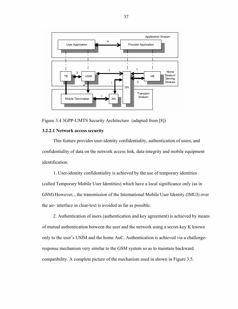
Figure 3.4 3GPP-UMTS Security Architecture (adapted from [8])
3.2.2.1 Network access security
This feature provides user-identity confidentiality, authentication of users, and
confidentiality of data on the network access link, data-integrity and mobile equipment
identification.
1. User-identity confidentiality is achieved by the use of temporary identities
(called Temporary Mobile User Identities) which have a local significance only (as in
GSM).However, , the transmission of the International Mobile User Identity (IMUI) over
the air- interface in clear-text is avoided as far as possible.
2. Authentication of users (authentication and key agreement) is achieved by means
of mutual authentication between the user and the network using a secret-key K known
only to the user’s USIM and the home AuC. Authentication is achieved via a challenge-
response mechanism very similar to the GSM system so as to maintain backward
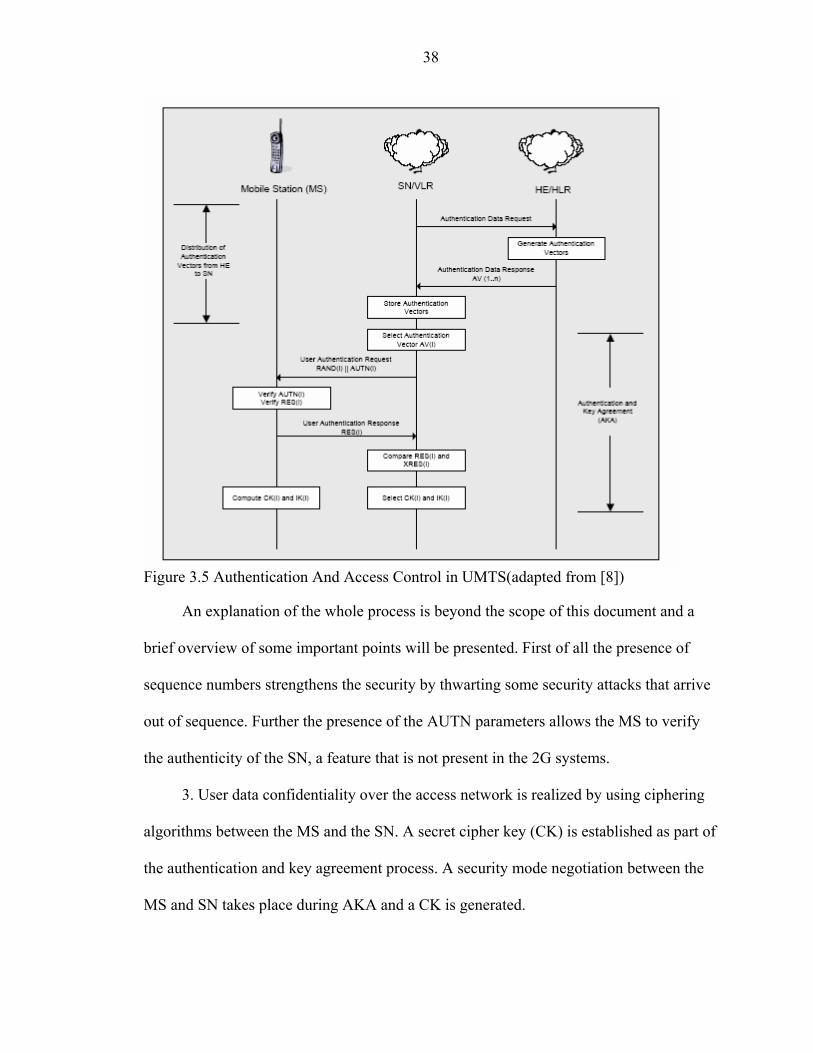
compatibility. A complete picture of the mechanism used in shown in Figure 3.5.
38
Figure 3.5 Authentication And Access Control in UMTS(adapted from [8])
An explanation of the whole process is beyond the scope of this document and a
brief overview of some important points will be presented. First of all the presence of
sequence numbers strengthens the security by thwarting some security attacks that arrive
out of sequence. Further the presence of the AUTN parameters allows the MS to verify
the authenticity of the SN, a feature that is not present in the 2G systems.
3. User data confidentiality over the access network is realized by using ciphering
algorithms between the MS and the SN. A secret cipher key (CK) is established as part of
the authentication and key agreement process. A security mode negotiation between the
MS and SN takes place during AKA and a CK is generated.

39
4. Data Integrity is the property that the data has not been altered in an
unauthorized manner. This is a new security feature included in the 3G Systems. Most of
the signaling information on the access link is considered to be very sensitive and must
be integrity protected. The UMTS integrity algorithm along with an integrity key (IK)
will be used for providing data integrity. IK is established as a part of the AKA process.
The actual integrity algorithm to be followed is realized by means of a security mode
negotiation between the MS and SN. Thus the MS and the SN can now verify the
authenticity of the signaling information received by each other.
5. Mobile equipment identification is done using an International Mobile
Equipment Identifier (IMEI) that uniquely identifies mobile equipment. (Similar to the
GSM system).
3.2.2.2 Network domain security
Network domain security provides entity authentication, data confidentiality
(between exchanges involving network elements), data integrity, and fraud information
gathering system. This functionality is important where sensitive signaling information
has to be exchanged between different network elements.
This feature is implemented using a 3-layered architecture.
The first layer of network domain security is a secret key transport mechanism
based on an asymmetric cryptosystem and is aimed at agreeing on a symmetric session
key for each direction of communication between two networks X and Y. (for network
elements belonging to the same network operator, layer-1 is not required). Key exchanges
take place between certain elements called the key administration centers (KACs) of the
network operators X and Y. During this stage, the cipher and integrity Keys (CK and IK)
for protecting the signaling data are also established.

40
In the second layer, the agreed symmetric keys for sending and receiving data are
distributed by the KACs in each network to the relevant network elements. This takes
place within the network of a single operator. It is clear that the distribution of the
symmetric keys to the network elements must be carried out in a secure way, as not to
compromise the whole system. Special key distribution mechanisms are in place to
support this feature.
In the third and final layer the distributed symmetric keys are used for securely
exchanging sensitive data between the network elements of one operator (internal use) or
different operators (external use) by means of a symmetric encryption algorithm. The
encrypted (authenticity / integrity protected) messages will be transported via the MAP
protocol.
3.2.2.3 User domain security
According to its definition this feature provides user to USIM Authentication and
USIM to Terminal Authentication. The user to USIM authentication is accomplished by
the means of a secret (a PIN) that is stored securely in the USIM. The user can have
access to the USIM only if he/she proves knowledge of the secret. The user to Terminal
Authentication is accomplished by using a secret that is stored securely in the USIM and
the Terminal.
3.2.2.4 Application security
The 3G Systems will provide the capability for operators or third party providers to
create applications which are resident on the USIM (similar to SIM Application Toolkit
in GSM). Thus, there exists a need to secure messages which are transferred over the 3G
network to applications on the USIM, with the level of security chosen by the network

41
operator or the application provider. The features provided to ensure security of messages
are
• Entity authentication of applications. • Data origin authentication of application data. • Data integrity of application data. • Replay detection of application data. • Sequence integrity of application data. • Proof of receipt.
The robustness of these systems with respect to security features is yet to be tested.
However, from the above discussions, it is evident that the security levels provided the
3G systems will far exceed those provided by the earlier cellular telecommunication
systems and even the contemporary wired public telecommunication systems.
The next chapter discusses the standards and activity with respect to wireless local
area networks and internet based standards.

CHAPTER 4 WIRELESS LOCAL AREA NETWORK AND INTERNET AUTHENTICATION
STANDARDS
When the IEEE 802.11 standard for wireless local area networks (WLANs) was
first released, there were no security features present. However, as wireless LANs were
deployed, the need for security became apparent. This led to the development of the
wired equivalent protocol (WEP) which was aimed at providing security on the wireless
LANs that would be equivalent to that on wired LANs.
To Wired Backbone
Figure 4.1 Wireless Local Area Network Architecture
Figure 4.1 shows the WLAN architecture. A WLAN is characterized by an access
point (AP) that is connected to a wired backbone, leading to either the Internet or a Web
Server. The AP forms the focal point for communication for wireless mobile terminals
like laptops and PDAs.
42

43
4.1 802.11 WEP Protocol
The WEP algorithm [25] was selected to meet the following criteria:
• “Reasonably strong”
• Self-synchronizing. Stations quite frequently go in and out of coverage.
• Computationally efficient. The WEP algorithm may be implemented in hardware or software.
• Exportable. It can be exported outside the US and imported to other countries.
• Optional. It is an option not required in an 802.11-compliant system.
The WEP Protocol also uses the same key is used to encrypt and decrypt the data.
4.1.1 WEP Encryption and Decryption
WEP security for plaintext data is a two step process. The first step encrypts the
plaintext, while the second protects against unauthorized data modification. The 40-bit
secret key is concatenated with a 24-bit initialization vector (“IV”) resulting in a 64-bit
total key size. The resulting key is input into a pseudorandom number generator (PRNG)
which outputs a pseudorandom key sequence based on the input key and the RC4
algorithm.
RC4 was developed in 1987 by Ron Rivest for RSA Data Security. RC4 is a stream
cipher that takes a fixed length key and produces a series of pseudorandom bits that are
XOR’ed with the plaintext to produce ciphertext and vice versa. RC4 is used in the
popular SSL Internet protocol and many other cryptography products.
The resulting sequence is used to encrypt the data by doing a bitwise XOR. This
results in encrypted bytes equal in length to the number of data bytes that are to be
transmitted in the expanded data plus 4 bytes. Thus the key sequence is used to protect
the integrity check value (ICV, 32-bits) as well as the data. To protect against

44
unauthorized data modification, an integrity algorithm (CRC-32) operates on the
plaintext to produce the ICV.
The ciphertext is accomplished over the following steps:
1. Compute the ICV using CRC-32 over the message plaintext.
2. Concatenate the ICV to the plaintext.
3. Choose a random initialization vector (IV) and concatenate this to the secret key.
4. Input the secret key+IV into the RC4 algorithm to produce a pseudorandom key sequence.
5. Encrypt the plaintext+ICV by doing a bitwise XOR with the pseudorandom key sequence under RC4 to produce the ciphertext.
6. Communicate the IV to the peer by placing it in front of the ciphertext. The IV, plaintext, and ICV triplet forms the actual data sent in the data frame.
In decryption, the IV of the incoming message is used to generate the key sequence
necessary to decrypt the incoming message. Combining the ciphertext with the proper
key sequence yields the original plaintext and ICV. The decryption is verified by
performing the integrity check algorithm on the recovered plaintext and comparing the
output ICV’ to the ICV transmitted with the message. If ICV’ is not equal to ICV, the
received message is in error, and an error indication is sent to the MAC management and
back to the sending station. Mobile units with erroneous messages (due to inability to
decrypt) are not authenticated.
4.1.2 WEP Authentication
The same shared key used to encrypt/decrypt the data frames is also used to
authenticate the station which is considered a security flaw in WLANs. There is also a
method where stations and AP’s can utilize WEP alone without shared key
authentication, essentially using WEP as an encryption engine only. This is done in open

45
system mode and is considered to be the most protected implementation in 802.11 thus
far, and it still enables reasonable authentication.
There are two types of 802.11 authentication: open system authentication and
shared key authentication.
The open system authentication is the default authentication service and does not
have any authentication mechanism. The station can associate with any access point and
listen to all data that are sent plaintext. This is usually implemented where ease-of-use is
the main issue, and the network administrator does not want to deal with security at all.
Such systems would be in use in small office or home environments.
Shared key authentication uses a shared secret key to allow the AP to validate the
wireless station. The secret shared key resides in each station’s MIB in a write-only form
and is therefore only available to the MAC coordinator. Figure 4.2 describes the shared-
key authentication.
The shared-key authentication process is as follows:
1. A requesting station sends an authentication frame to the AP.
2. When the AP receives an initial authentication frame, it will reply with an authentication frame containing 128 bytes of random challenge text generated by the WEP engine in standard form.
3. The requesting station will then copy the challenge text into an authentication frame, encrypt it with a shared key, and then send the frame to the responding station.
4. The receiving AP will decrypt the value of the challenge text using the same shared key and compare it to the challenge text sent earlier. If a match occurs, the responding station will reply with an authentication indicating a successful authentication. If not, the responding AP will send a negative authentication.

46
Figure 4.2 Shared – Key Authentication (adapted from [25])
4.1.3 Problems with WEP
Unfortunately, the WEP protocol has been discovered to have innumerable flaws
which have made its applicability very risky [25, 26]. The WEP PRNG (RC4) is the
critical component of the WEP process, since it is the actual encryption engine. The IV
extends the useful lifetime of the secret key and provides the self-synchronous property
of the algorithm. The secret key remains constant while the IV changes periodically.
Each new IV results in a new key sequence. Thus there is a one-to-one correspondence
between the IV and the output. The IV may change as frequently as every message, and
since it travels with the message and the receiver will always be able to decrypt any
message. Therefore the data of higher layer protocols (e.g., IP) are usually highly
predictable. An eavesdropper can readily determine portions of the key sequence

47
generated by the (Key, IV) pair. If the same pair is used for successive messages, this
effect may reduce the degree of privacy.
Changing the IV after each message is an easy way to preserve the effectiveness of
WEP. However, WEP is vulnerable because of relatively short IVs and keys that remain
static. With only 24 bits, WEP eventually uses the same IV for different data packets. For
a large busy network, this reoccurrence of IVs can happen within an hour or so. This
results in the transmission of frames having keystreams that are too similar. If a hacker
collects enough frames based on the same IV, the individual can determine the shared
values among them, i.e., the keystream or the shared secret key. This of course leads to
the hacker decrypting any of the 802.11 frames.
The static nature of the shared secret keys emphasizes this problem. 802.11 does
not provide functions that support the exchange of keys among stations. As a result,
system administrators and users generally use the same keys for weeks, months, and even
years. This gives mischievous culprits plenty of time to monitor and hack into WEP-
enabled networks. Some vendors deploy dynamic key distribution solutions based on
802.1X, which improves the security of wireless LANs.
Internet-based mobility and wireless access builds upon Mobile IP protocol and a
centralized authentication, authorization and accounting (AAA) protocol. Next, the
Mobile IP AAA techniques are discussed.
4.2 Internet Authentication
AAA protocols play an important role in enabling global Internet connectivity. In
the roaming scenario, a remote-end user is authenticated by a visited ISP as against a
home ISP. This task is accomplished by the presence of a server that supports the AAA
services in a distributed fashion. In this scenario, the home ISP maintains a master server

48
for its subscriber base to support access control and billing. Additionally, a third-party
server or broker could also be used to scale this approach and reduce the configuration
requirements on a proxy server. The most popular client/server AAA mechanism
deployed in the Internet is the Remote Access Dial-In User Service(RADIUS) [25].
4.2.1 RADIUS
The functional attributes of RADIUS are the following:
• Client – Server based operations. A RADIUS client resides on the Network Access Server (NAS) and communicates with a RADIUS server. In some circumstances, a RADIUS server may also act as a proxy client for another RADIUS or authentication server.
• Network Security. All communication between the RADIUS clients and server are authenticated by a shared secret key. This key is never transmitted over the network.
• RADIUS can support multiple authentication mechanisms such as PAP and CHAP discussed in section 2.2.3.
• Attribute/Value Pairs. RADIUS messages carry the AAA information encoded in type length value fields. These are called attribute value pairs or AVPs. Examples of AVPs include Username, password and so on.
• RADIUS uses UDP/IP to forward messages over the network.
RADIUS continues to enjoy widespread support among ISPs. However, the
protocol was engineered only for small network devices and supporting a few end-users
requiring simple server based authentication. However ISPs today use AAA servers for
thousands of concurrent end users. This burdens the functional capabilities of RADIUS,
and has led to the development of a more robust, scalable protocol Diameter.
4.2.2 Diameter
Diameter is a lightweight, peer based AAA protocol. It has been designed to offer a
scalable foundation for new policies and AAA services over existing (PPP) and emerging

49
(Mobile IP) network technologies. In essence, it employs the same mechanisms as
RADIUS, including UDP transport, encoded AVPs and proxy server support.
Diameter however has some advantages over RADIUS. It has a peer-to-peer nature,
with explicit support for intermediaries. It supports a much larger attribute-value length,
as against 255 bytes in RADIUS, and incorporates a window-based transport that permits
a Diameter server to transmit as many messages as the NAS or receiver can handle.
Traditionally, RADIUS permits only 255 messages to be outstanding before receiving an
acknowledgement. Diameter also allows for unsolicited server messages to its client,
which is useful if the server needs to instruct the NAS to perform a specific accounting
function or to terminate a connection.
Diameter has integrated accounting functions. It also employs transport layer
retransmission as well as a fail-over scheme that provides improved network resilience.
Finally, to ensure that the AAA framework is not compromised in any manner it provides
for stronger peer-to-peer security as well as optional end-to-end payload security.
The biggest advantage of Diameter is its inherent support for roaming and Mobile
IP. Diameter servers can function as brokers, and this facilitates AAA service delivery to
roaming and Mobile IP end users attached to a visited foreign network and accessing
resources on the home network. In such situations, the Diameter broker communicates
with the ISP in the visited network as a peer to execute AAA functions. Any
communications between the server and the broker are performed over a secure
connection. In addition, the broker can act as a Certificate Authority (CA). This role
makes the task of distributing certificates to servers a lot more scalable and efficient.

50
The role played by AAA servers and their protocols will assume greater importance
in the networks of the future. The demands made on mobility management in the future,
with greater global roaming, and inter-system activity, will make the AAA servers the
cornerstone of the backbone networks.
The next section discusses the emerging Mobile IP network, and the use of the
AAA framework for security.
4.3 Mobile IP
Mobile IP is a proposed standard protocol that builds on the Internet Protocol by
making mobility transparent to applications and higher level protocols like TCP [28, 29,
30, and 31]. To maintain the existing transport layer connections as a mobile device
moves across networks, it must keep its IP address same. However, the mobile node does
change its IP address at every new point of attachment as it moves across networks.
Mobile IP solves this problem by using two IP addresses – a home address and a care-of
address.
The home address is static and is used to identify the TCP connections. This means
that for any node that is communicating with the mobile node, the home address will be
the constant point of communication, so that transport layer connectivity can be
maintained. The care-of-address is the address provided to the mobile node by the foreign
network and is the actual point of attachment. This care-of-address is provided by a
special foreign agent in the foreign network or by a Dynamic Host Configuration
Protocol (DHCP) server. The agent that manages the home IP address is called the home
agent.
A typical communication scenario in Mobile IP is explained in figure 4.3.

51
The flow of packets corresponding to the figure is as follows:
5. The correspondent node communicates with the mobile node when it is in its home network. At this point it communicates to the home address.
6. When the mobile node moves away from its home network to the foreign network, it obtains a care-of address from the foreign agent.
7. This care-of address is registered with the home agent.
8. Packets destined for the mobile node, continue to arrive at the home agent from the correspondent node. But the home agents tunnel these packets to the foreign agent which in turn passes the packets to the mobile node.
9. The mobile node replies to the correspondent node directly.
Figure 4.3 Mobile IP Communication
4.3.1 Mobile IP with AAA
The AAA server is a server program that handles user requests for access to
computer resources and, for an enterprise, provides AAA services. The AAA server
typically interacts with network access and gateway servers and with databases and
directories containing user information. The current standard by which devices or
applications communicate with an AAA server is RADIUS.
This model is based on the currently existing security and authentication features
offered by the wired model, when providing dial-up access to a client even when he is not

52
in his own domain. It relies on the existence of servers that are capable of performing
AAA services [30]. There are several closely related solutions, each extensions of the
previous using the AAA architecture. Fig 4.4 describes the basic model.
This is a modified version of the original Mobile IP architecture, in that it includes
a new entity the AAAF and AAAH – AAA servers at the Foreign domain and Home
domain respectively. A secure channel connects the two AAA servers to each other
It is required that the Foreign Agent (FA) has no access to the data that is crucial in
completing the security transaction. Connections between the FA and the AAAF are
deemed secure. The AAAF itself may not be able to perform all the AAA actions for the
mobile node, and will have to consult with the AAAH. The information about the AAAH
and the home domain of the mobile node are obtained from the data from the mobile
node. Again the AAAF also should not have full access to all the data.
Figure 4.4 Internet AAA Architecture for Mobile IP
This architecture requires the existence and creation of several security associations
(SA):
SA1 – between MN and AAAH
SA2 – between AAAH and HA

53
SA3 – between AAAH and AAAF
SA4 – between AAAF and FA
Several requirements have been identified for this model – with the trust
relationships that exist.
• Each FA must have a secure relationship with its AAAF.
• The AAAF and AAAH must be able to share information in a secure manner.
• The FA should be able to keep the state of the customer information while it is being verified.
• Often, requests from several MNs may have to be managed by the same FA.
• The MN should be able to provide “unforgeable” credentials about itself without consultation with its HA, so that the AAAF and AAAH can authenticate it quickly.
• The FA should protect against replay attacks.
• None of the intervening nodes should be able to glean any (secret) information about the MN.
IP connectivity based requirements –
• The AAAF should be able to obtain an IP address for the MN
• AAAF should be able to identify the client by some means other than its IP address.
It has been understood that after the initial registration, the AAA servers are not
that important and further communication may take place on the traditional Mobile IP
path. Also, that during the initial registrations, the AAA servers should pass on security
features like keys so that thereafter the FA and HA can manage the scenario.
4.3.2 Various Mobile IP scenarios for AAA servers
Mobile IP with dynamic addresses – This is the classical mobile IP scenario where
it is the responsibility of the foreign domain to provide an IP address to the mobile node.
All the MN should have for this purpose is a NAI – Network Access Identifier.

54
Firewalls and AAA – In the papers described before this, I had noticed
considerable problems faced by mobile ip due to the existence of firewalls. Several
solutions were provided. The author has proposed that since a firewall and the AAA
server could be part of the same administrative domain, the AAA server could keep the
firewall informed about the mobile node. It could do this by passing on keys and control
messages to configure the firewall in accordance to the mobile node.
Mobile IP with local payments – The situation above may be simplified if the
AAAF performs accounting transactions at the foreign domain itself – i.e. charge the user
at his local point of connectivity itself.
Broker Model – In this case, a broker node exists between the AAA servers of the
home and foreign networks. This tries to provide an alternative to the security
relationship that must be established between the AAA servers. It enables the various
networks to interact without the formation of any formal relationship between them.
Again, the requirement that the nodes must not have any access to the (secret) data for
mobile IP applies to the broker.
4.3.3 Protocol Flow Control
Registration Request Protocol – Figure 4.5 provides the request protocol flow. To
ensure against replays the FA makes use of a new mobile IP extension called the
“challenge extension”. The MN is required to add this extension to all its subsequent
messages.

55
Figure 4.5 AAA Architecture with Security Associations
1. FA advertises a challenge 2. MN adds NAI, challenge response, to the Mobile IP registration request. 3. FA sends the request to the AAAF 4. AAAF (proxy) looks up NAI, find the AAAH 5. AAAF sends request to AAAH 6. AAAH authenticates the request, it may allocate a HA and IP address for the MN.
Key Generation – The MN needs a security association with its HA. Also for other
features like smooth handoff, the MN needs a key for communication. Again, the FA also
needs an association with the HA. The best way to distribute these keys is during
registration by the AAA. The following keys are generated:
K1 – between MN and FA
K2 – between MN and HA
K3 – between FA and HA
However, to distribute these keys, they need to be encoded according to the
specifications of the AAAH. This results in the AAAF learning keys for associations it
does not need. But this facility helps in smooth handoffs. Also, each key gets encrypted
twice:
K1, K2 – using SA1 -> MN

56
K1, K3 – using SA3 –> FA
K2, K3 – using SA2 -> HA
Registration Reply Protocol
Figure 4.6 AAA Architecture with Security Associations during Registration Reply
Figure 4.6 explains the registration reply protocol. The signaling associated with
the numbers in the figure is explained below.
7. AAAH issues a request to HA with K2, K3
8. HA creates a reply using K2 and K3 for FA.
9. HA sends results to AAAH which “proxies” the result to the AAAF.
10. AAAF decrypts K1 & K2 using SA3, re-encrypts using SA4.
11. FA decrypts K1 and K3 using SA4 and establishes the FA-HA communication and MN-FA communication channels.
12. MN decrypts K1 and K2 using SA1 and establishes the MN-FA authentication.
This section concludes our description of the various wireless networks and the
security mechanisms employed by them. We have now obtained sufficient background in

57
the area of wireless networks and security, and are ready to take a glimpse at the future.
The next chapter introduces the new Authentication Protocol: VISA.

CHAPTER 5 VISA: AN ADVANCED INTER-SYSTEM AUTHENTICATION PROTOCOL
As mentioned in the Introduction, a diverse, multi-network wireless environment is
planned for future wireless systems, which is quite desirable for users who wish to access
multiple services from different networks, for the benefit, i.e., to gain more bandwidth,
the desired quality of service, etc. However, allowing users to move between different
types of networks creates problems for security, in that authentication becomes a
distributed, disconnected process. As described in Chapters 3, well-established cellular
systems, such as GSM, provide authentication services through a centralized
authentication center, in cooperation with home and visitor location registers. However, a
diverse, multi-network environment does not yield itself to a centralized authority, nor is
there any existing mechanism to enable networks to validate users that roam between
different networks or service providers.
Fishwat, Nofal and Tadros[32] suggested a new protocol which included the use of
mutual authentication between communication entities. It was designed over existing two
and three-party authentication and key distribution protocols, which were implemented in
KryptoKnight, an authentication and key distribution service developed by IBM research.
The user contacts a remote Authentication Server (AS), which in turn establishes a secure
association with the user’s home AS. The two Authentication Servers mutually
authenticate each other, and then authenticate the mobile terminal. The home AS also
provides the remote AS with a session key to be used between the remote AS and the
58

59
user. This approach aims at securing the communication line between the home server
and a visitor server. However, the bottleneck at the home server continues to exists.
Hwang and Chang[33] proposed a Self-Encryption mechanism for authentication of
roaming services. It improves over previous protocols like by dramatically reducing the
number of messages transmitted between a user and the visiting server, and those
between the visiting server and the home server. It thus reduces the bandwidth
requirement.
In this chapter, an adVanced Inter-System Authentication (VISA) process is
proposed, to assist in the validation of unknown users who have an established account
history with a previous network [34, 35]. First, the proposed authentication server
architecture is described. Then, two new authentication mechanisms are introduced,
which are designed to facilitate the communication of authentication information between
different types of networks. Next, implementation issues are discussed, such system
entries, repeat entries, and key exchange protocols. Finally, a performance analysis of the
new technique is provided through an OPNET modeler simulation study that explores the
additional processing and signaling loads imposed on the network by the new protocol,
and an implementation of the protocol in Java.

60
5.1 AdVanced Inter-System Authentication Architecture
Figure 5.1 AdVanced Inter-System Authentication Architecture
Figure 5.1 shows the proposed inter-system roaming architecture. System A and
System B represent two disjoint networks where a user may request connectivity, such as
a wireless LAN overlapped by a cellular system. The separation between the systems
shown in Figure 5.1 can be a logical or a physical separation, to include the consideration
of multiple networks that overlap within a single coverage area. In the visa architecture,
each network has at least one server that is responsible for establishing inter-system
communication agreements with partner networks. These agreements address billing
requirements, rental charges for service providers, limitations on usage, and other
account-related information.
The visa architecture is an extension of the current research for authentication,
authorization and accounting (AAA) being conducted by the Internet Engineering Task
Force (IETF). As described in Chapter 4, the IETF has developed an architecture for
61
Mobile IP that includes AAA servers for the home domain and foreign domain, enabled
to exchange encrypted messages. Although AAA brokers have been proposed to establish
security associations with AAA servers in other networks, little research has been done
with respect to the implementation, operation, and performance issues for establishing
such a broker [3]. In this thesis, such an implementation is proposed, and the performance
issues are explored using the OPNET modeler network simulation platform. The
description of the visa approach begins with the mechanisms that will facilitate the
message exchange between networks: the mobile node passport and mobile node visa.
(Note: The acronym of the protocol and one of the sub-mechanisms share the same
name. To distinguish between the two, the protocol is referred to as "VISA" in capital
letters, and the mechanism is referred to using the phrase "mobile node visa" in lower
case.)
5.2 Mobile Node Passport
The mobile node passport represents both an authentication document and the
security association between a mobile user requesting inter-system roaming and its home
system. It is issued by the user's home system at the time of the user's account initiation
(or account upgrade), and becomes the chief form of identification for a user account that
has requested the inter-system roaming option. Thus, roaming permissions are set by the
user's home service provider, according to the needs and desires of the user, and also
according to any pre-established security associations that exist between the user's home
network and another network. Once the passport is generated, the client in the home
network stores the mobile node passport and is responsible for updating the passport
record as necessary.

62
Figure 5.2 shows the structure of the mobile node passport. The mobile node
passport contains data about the mobile node, such as its identity, origin network and
home server information. It is signed using the authentication server's private key, and
either the DSA or RSA algorithm. Then, a hash of the entire passport is generated using
MD5 or SHA1, and finally the server digitally signs the passport using the generated
hash. (The RSA algorithm and hash functions are described in Chapter 2.)
The fields of the passport as shown in Figure 5.2, are described as follows:
• Passport Number – Unique identifier for the passport. It includes a one-way hash to provide security from forgeries.
• Passport Origin Server ID
• Passport Origin Server Address Type – The type of address of the Origin Server, e.g. IP address, telephone number etc.
• Passport Origin Server Address
• Passport issue date and time AVP –UTC date and time that the passport was generated. Allows for a prior generation of the passport. The date and time is of the form yyyy-mm-ddThh.mm.ss.mmm-xxzz, where yyyy is the year, mm the month, dd the day, hh the hour, mm the minute, ss the second, mmm the millisecond and xxzz is the time zone expressed as a difference (either + or -) of the local time to the UTC time in hours (xx) and minutes (zz). This format follows the ISO8601:1988 conventions.
• Passport Lifetime – The period for which the passport is valid.
• Passport Authentication Key - A set of variables that describe the Passport’s authentication key. This key will be used for authenticating the passport and for establishing sessions with other servers.
o Passport Authentication Key Number
o Passport Authentication Key Lifetime – The time for which the passport authentication key number is valid.

63
Figure 5.2 Structure of the Passport
Passport DEFINITIONS AUTOMATIC TAGS ::= BEGIN Passport-Number ::= OBJECT IDENTIFIER O-S-address-type ::= IA5String Origin-Server-ID ::= IA5String Origin-Server-Add ::= IA5String Passport-Issue ::= UTCTime Lifetime ::= UTCTime Authentication-key ::= SEQUENCE { auth-key OBJECT IDENTIFIER, key-lifetime UTCTime } Mobile-device ::= SEQUENCE { Mobile Device ID OBJECT IDENTIFIER, Mobile Device Permanent Address Type IA5String Mobile Device Permanent Address IA5String Mobile Device Origin Network Type IA5String Mobile Device Origin Server Address Type IA5String Mobile Device Origin Server Address IA5String Mobile Device Lifetime UTCTime Mobile Device Security ::= CHOICE { iPSec IA5String, tLS IA5String } Mobile Device Passport Issue date and time UTCTime Mobile Device Passport Expiration UTCTime } Signature ::= SEQUENCE {} END
• Passport Billing Record – A set of variables that describes the billing record associated with the passport. The billing record has not been formalized in the ASN.1 syntax and is currently optional.
o Passport Billing Record Number
o Passport Billing Record Key - A set of variables that describe the billing record’s key.
o Passport Billing Record Key Number
o Passport Billing Record Key Lifetime - The period for which the billing record key is valid.
• Passport Mobile Device - A set of variables that uniquely represent the mobile device to whom the passport has been issued.

64
o Mobile Device ID – The identifier for the mobile device holding the passport is issued. It includes a hash function to protect against forgery.
o Mobile Device Permanent Address Type
o Mobile Device Permanent Address
o Mobile Device Origin Network Type – This variable describes the origin network associated with the mobile device, e.g. Cellular, Internet. WLAN etc.
o Mobile Device Origin Server Address Type
o Mobile Device Origin Server Address
o Mobile Device Lifetime – The duration of time for which the mobile device is valid.
o Mobile Device Security – The type of security on the mobile device. This could be either transport layer security (TLS) or IP security (IPSEC).
o Mobile Device Account ID – This variable identifies an account maintained by the origin network for the mobile device. (Optional)
o Mobile Device Authorization ID – This variable identifies the authorization information maintained by the origin network for the Mobile Device. (Optional)
o Mobile Device Passport Issue Date and Time
o Mobile Device Passport Expiration
• Passport Digital Signature – The passport must be digitally signed by the issuing authority to establish its authenticity and to protect against forgery. The signature can be generated using a message digest of the passport. In this case, a digest of the passport is computed using MD5 as described in Chapter 2, and then the signature is produced using this digest. This has the advantage of securing the passport, and at the same time making it less bulky when compared to a Public Key signature.
Pseudo-code:
(Signature ( MD5-RSA) ( Digest : = MD(Passport) ) ( Signature : = RSA(N,D,MD(Passport)) )
The passport has been designed room for flexibility. It has provision for various
types of addresses, such as IP, cellular, telephone numbers etc. It has parameters to

65
connect the passport with accounting servers, so that billing records may be quickly
established in the foreign network. There is clear indication that a passport may be
developed at one time, but assigned to a mobile terminal at another time. Hence, it allows
for an efficient management of the data store associated with the passport. While the
passport associates the mobile node with its home system, a mobile node visa is needed
to authorize the mobile node to use the resources of a different network or service
provider. The mobile node visa is described next.
5.3 Mobile Node Visa
A set of mobile node visas per user is issued according to the different networks the
user wishes to access. The mobile node visas can be generated at the time of service
initiation, or they cab be requested individually as a service add-on, as the user changes
his or her network environment. For example, an IS-136 user traveling from the U.S. to
Europe may request a GSM visa from his or her service provider. The visa would then
consist of the download (via smart card or software download) of a terminal
identification number for GSM operation, as well as authorizations to receive certain
types of services. The length of time that the mobile node visa is active depends on the
agreement between the IS-136 service provider and the GSM service provider, likewise
for the pricing attributed to the cost of providing the user with resources in the new
network.
The structure of the mobile node visa is illustrated in Figure 5.3 and is described as
follows:
• Visa Number - This number uniquely identifies a mobile node visa within the foreign network. It includes a one-way hash for protection against forgery.
• Origin System Network Type – The type of network associated with the mobile node visa.

66
• Origin System Address Type
• Origin System Address
• Visa Passport Number
• Visa Issue Date/Time
• Expiration Date/Time
F
•
•
•
•
Visa DEFINITIONS AUTOMATIC TAGS ::= BEGIN Visa-Number ::= OBJECT IDENTIFIER Visa-Issue ::= GeneralizedTime Expiry-Date-Time ::= GeneralizedTime System-NW-Type ::= IA5String Server-Add-Type ::= IA5String Server-Address ::= IA5String Security ::= CHOICE { iPSec IA5String, tLS IA5String } Authentication-Key ::= SEQUENCE { auth-key OBJECT IDENTIFIER, key-lifetime UTCTime } Mobile Device Details ::= SEQUENCE{
Mobile Device ID OBJECT IDENTIFIER Passport Number OBJECT IDENTIFIER Mobile Device Permanent Address IA5String Passport Origin Server IA5String
}
igure 5.3 Structure of the Mobile Node Visa
Number of Entries Permitted – The maximum allowed number of entries to the foreign system. (Optional)
Entry Lifetime (Optional)
Visa Security – The type of security mechanism used.
Authentication Key – A set of variables that describes the authentication key associated with the mobile node visa.
o Authentication Key Number
o Authentication Key Lifetime

67
o Authentication Algorithm – Algorithm used in the particular foreign network for authentication.
• Mobile Device Details – These details bind the visa to the particular mobile device that it is issued for. It also binds the visa and the mobile node to the passport issuing server.
• Visa Digital Signature – This signature is required to establish the authenticity of the mobile node visa and establish the accountability of the issuing server. A digest of the mobile node visa can be generated using MD5. Thereafter, a signature is computed and appended to the mobile node visa.
As mentioned previously, the mobile node passport and mobile node visa together
are exchanged with the home and foreign networks to provide identification and
authentication. The structure of the passport can be maintained for all mobile devices
requesting services in an inter-system environment, and can be issued by any home
authentication server. The mobile node visa on the other hand, is local to a particular
network. There is a basic structure, which can then be enhanced or modified according to
the conventions followed in each type of network. Thus, a visa can only be obtained
through the trusted security alliances provided in the Visa Authentication Architecture.
The procedures required to obtain a mobile node passport or a mobile node visa are
described next.
5.4 Obtaining a Mobile Node Passport and a Mobile Node Visa
The mobile device can obtain the passport from its origin server or from any other
server in its home network. The specific policies involved in obtaining a passport would
be network type dependent. The process of determining whether a mobile device should
have inter-system access must be that of the owner of the device and the home service
provider. At any point in time, the owner of the mobile device may request the addition
of the inter-system access to his/her customer service people. At this point, the home
service provider connects to the origin server to generate a passport for the device.

68
To obtain a mobile node visa, the home service provider must contact an
authentication server in each of the selected networks. Thus a mobile node visa issuance
requires that both the home server and the selected network belong to the same Visa
Server Architecture network. Although the Visa server architecture requires the backbone
networks of two disjoint technologies to communicate, this is a reasonable approach as
work in this field is already being done [27, 32 and 33].
Figure 5.4 Request for Visa
The inter-server signaling steps required to obtain a mobile node visa from a
foreign network are shown in figure 5.4, based on the architecture shown in figure 5.1
and a user in network A requesting a mobile node visa from network B.
The “request for visa” exchange in figure 5.4 includes the following entities:
• Visa Request Number

69
• Date and Time of Request • Origin System Name • Mobile Device ID • Mobile Device Origin Server Address • Mobile Device Permanent Address • Type of visa required
Figure 5.5 Visa Request PDU
Visa Request PDU
Request Number
Time Stamp Error Information
Applicable Error/Reason: None VISA Request Information Field Details: Passport Number Origin System Name Mobile Device ID Mobile Device Origin Server Address Visa Type
Mobile Device Permanent Address
To prevent attacks by snooping agents the request number, date and time of request
are used as a nonce and a timestamp respectively. The entire request is then encrypted
using the session key. The protocol data units for the visa request and visa reply
components of the above handshake are illustrated in figures 5.5 and 5.6.
Once the request is received and validated the target server generates a mobile node
visa. A non-valid exchange, resulting in rejection, might result from events such as –
network capacity being reached, errors in the request, or a network failure. A rejection
response contains only a response ID and a status indicating the reason for the decline.
The request also employs a timeout mechanism to protect against network failures.

70
Now that the passport and visa have been issued to the mobile node, the user is
ready to access the resources of a foreign network. The next section discusses the steps
involved when the mobile node enters a foreign network.
Figure 5.6 Visa Response PDU
Visa Response PDU
Response Number
Time Stamp Error Information
Applicable Error/Response:
1. resourceUnavailable 2. commitFailed 3. authorizationError 4. inconsistentName
VISA Reply Information Field Detail – VISA packet
5.5 Entering a Foreign System
When any mobile node enters a new network, it sends information to the network
access entity, i.e., a wireless access point or base station. In the VISA protocol, the
mobile includes the passport in the transmitted information. The network access entity
retrieves the passport and routes it to the network VISA authentication server, referred to
as a VISA center. The reception of the passport enables the new network's VISA center
to begin a linked billing record, track the movements of the mobile node, and to store
authentication keys for the mobile node's current session.
At the first arrival, the mobile node must establish service in the new network with
a full handshake with the visa center, as shown in Figure 5.7.

71
5.5.1 Full Handshake
The full handshake takes place between two entities, the mobile node (mobile
device) and the visa centre. The full handshake is initiated by a Hello from the mobile
Figure 5.7 Full Handshake
node.
ic
ring
blic
key, the visa centre could send a certificate with its public key. If this certificate is issued
The visa centre generates a response that includes a Hello and a VISA request for
the mobile node passport and the mobile node visa. The visa centre also sends its publ
key to the mobile node.
Since, a public key is public knowledge; there is no need to encrypt this key du
transmission. However, there should be a way to ensure the authenticity of the public
key. The current version of VISA assumes the authenticity of the public key. However, a
third party interceptor could easily replace the key with a fraudulent key. One of the
easiest ways to verify a key is to use certificate authorities. Instead of sending the pu

72
by a well known certificate authority, the mobile node would have the resources to
the authenticity of the public key. The full handshake can then proceed as follows.
In the next step, the mobile node encrypts its passport and visa with the visa
center’s public key and sends the items in an encrypted timestamped packet to the visa
centre. The timestamp provides protection from Denial-Of-Service and Replay attac
The Visa Centre decrypts the packet, registers the mobile node’s ID number in the new
network and establishes a connection with the mobile node’s billing record. It also
registers the mobile node’s authentication keys for future authentication. I
verify
ks.
n the final step
of the
e
th
nd battery. Although, the passport and visa have been constructed to be as
light- width
d
shake, while taking advantage of the mobile node state that has
been previously stored in the visa centre. This new process is referred to as the
abbreviated handshake.
full handshake, the visa center responds to the mobile node with a Response ID
enabling the mobile node to access the resources of the foreign network.
The full handshake is a secure way of identifying and authenticating a mobile nod
for its first entry into a foreign network. Consider the case where the mobile node leaves
and then accesses the resources of the foreign network. During each return access, the
mobile node is required to present its passport and visa. This process however, could be
rather expensive in terms of mobile node processing power and the wireless bandwid
and performing public key encryption is expensive in terms of processor power, time,
memory a
weight as possible, the final encrypted secure packet requires significant band
expense.
These factors led to the design of another authentication process that woul
complement the full hand

73
5.5.2 Abbreviated Handshake
Figure 5.8 Abbreviated Handshake
While the full handshake requires a full exchange of visa and authorization keys,
the abbreviated handshake uses the mobile node's response ID to retrieve the cached
information. The response ID is an increment of a response ID generated by the visa
center in the mobile node's previous attempt. If the visa center is able to identify the
cached copy of the mobile node's registered visa from previous sessions, the visa center
responds with a challenge. If the center is unable to locate the mobile node's visa, if the
visa has expired, or if any authentication key has expired, the visa center will respond
with a server hello and request the user's visa, as in a full handshake.
The challenge-response process is network specific. For example, GSM has used an
A3 and A8 algorithm, but 3GPP is developing enhanced algorithms, such as the F8

74
confidentiality algorithm and the F9 integrity algorithm. Using the visa mechanism, the
appropriate response to the challenge is a combination of the passport key and the visa
key, such as a function of A8(passport Key, visa Key), that results in a new key, K(p,v) to
be used by the mobile node for each new session. The key, K(p,v), is then used to
compute a response to a random challenge (rand(c)). At the visa server K(p,v) is also
generated by retrieving the saved passport and visa authentication keys obtained during
the Full Handshake. If the mobile node's response matches the visa server's result, then
the mobile node is given the requested access.
This form of challenge-response has several advantages. First, it reduces the
packet-size and delays involved in authenticating the mobile device in the new system.
Second, by using system specific algorithms, it removes the need to establish a special
algorithm for authenticating mobile devices not belonging to a particular system. The
only constraint lies in the specification of the algorithm parameters for a system specific
challenge response mechanism. The mobile node passport and mobile node visa provide
enough room for insertion for any of these parameters to suit the needs of a network.
5.5.3 Refreshing the Passport and Visa Keys
The lifetimes of the passport and visa entities are both maintained at the home
network. The passport key must be replaced by the user's home network. If the key
expires when the mobile device is in the foreign network, the mobile device is denied
service at the time of expiration. If the visa key expires before the mobile node enters (or
re-enters) a new network, then the mobile node uses the full handshake procedure to
obtain a replacement key that is assigned a special one-time session key for the exchange.
The passport and visa entities are created to provide a means for an unknown user
to be authenticated in a new network. However, the authentication process carries an
75
overhead that may be prohibitive. In the next chapter, a performance evaluation is
provided to demonstrate the overhead of the new protocol, as well as an implementation
of the protocol using Java.

CHAPTER 6 IMPLEMENTATION AND SIMULATION OF VISA
This chapter describes the construction of the prototype of the VISA protocol in
Java, the Uniform Modeling Language (UML) diagrams associated with the various
classes and the OPNET simulation. It concludes with the results obtained from the Java
emulation and OPNET simulation.
6.1 Java Implementation
The VISA protocol was implemented using the Java 2 Standard Edition (J2SE) (for
the wired network version), and the Java 2 Micro Edition (J2ME) (for the wireless
version). While the general approach remained the same for the wired and wireless
models, the wireless model required improvisation to compensate for the lack of
processing capabilities and memory available in a mobile device.
The protocol implementation required a security mechanism as well as a network
mechanism for signaling. These broad areas were accompanied by other issues such as
storage management, efficient memory management and processing delay.
The Java 2 Platform, Micro Edition, has been built to address the needs of the
several small devices that are rapidly gaining popularity. These devices include mobile
phones, pagers, PDAs as well as TV set-top boxes.
The Java 2 Platform Micro Edition, (J2ME) Wireless Toolkit are sets of tools that
provide application developers with the emulation environments, documentation and
examples needed to develop Java technology applications targeted at (Connected Limited
Device Configuration/ Mobile Information Device Profile) CLDC/MIDP compliant
76

77
mobile phones and entry level PDAs. It provides development features for Integrated
Over The Air emulation, Certificate management, Push Registry emulation, Monitoring
for all protocols (HTTP(S), Socket, datagram, Comm, SSL, SMS/CBS) and Compile and
Runtime selection of API extensions (WMA, MMAPI). The J2ME Wireless Toolkit has
support for performance monitoring and tuning. The toolkit includes:
Method Profiler: This enables the user to see application bottlenecks. The profiler
shows the methods the application called, how often they were called, and the time each
method consumed.
Memory monitor: It graphically shows the memory a MIDlet uses as it runs, the
current memory in use, and where the MIDlet is creating different types of objects.
Network monitor: It shows a MIDlet’s network connections and the values of all
HTTP requests and responses between the client and the server.
6.1.1 Java Security
The mobile node passport and the mobile node visa were implemented according to
ASN.1 design specifications using Java Security and Java Crypto APIs. The Java
Cryptography Extension (JCE) for Java Security provides a framework and
implementations for encryption, key generation and key agreement, and message
authentication code (MAC) algorithms. It also supports encryption for block and stream
ciphers, secure streams and sealed objects. The Java Crypto API and SunJCE provider
now available as part of J2SE v. 1.4, are available without any restriction in the United
States. But most of the cryptographic functions are opaque in nature i.e. the actual
working of the cryptographic functions is not available for public viewing.

78
The JDK(Java Development Kit) Security API is a Java core API, built around the
java.security package. Users can call API methods to incorporate security
functionality into their applications. The security features include digital signature,
message digest, key generation, and random number generation algorithms; keystore
creation and management services; algorithm parameter generation and management
services; and key and certificate "factories" for creating keys or certificates from existing
material (e.g., encodings).
6.1.2 Network Signaling Mechanisms
During an interaction with the mobile node, the visa centre first receives a mobile
terminal Hello as shown in figure 5.7. It then needs to determine from the mobile node’s
response ID if the mobile node has ever been authenticated before. On the other hand, the
mobile node examines the response from the visa centre to determine the type of
handshake. If the response indicates a full handshake, it extracts the visa center’s
encryption key, otherwise it extracts the challenge. For the full handshake, the mobile
node uses the instances of the passport and visa, encrypts them using the encryption key
and generates a sealed object. For the abbreviated handshake, a response to the challenge
is generated and then sent to the visa centre. The visa centre concludes the signaling with
the response ID, which is generated randomly and uniquely for each instance of the
mobile node.
6.1.2.1 Mobile node – visa centre signaling architecture
The communication between a mobile terminal and a visa centre is similar to the
client server architecture. Servers are powerful machines responsible for authentication
like the AAA servers for RADIUS or DIAMETER. The mobile nodes are assumed to be

79
simpler machines on which users run applications. The mobile node holds only a small
amount of information including its own passport and visa. It has limited processing
power in terms of encryption and algorithm computation. The visa centre on the other
hand, manages a repository of various mobile node passports and visas. It maintains logs
of the activity of all the mobile nodes in its realm, and is responsible for their
authentication and their updates. The visa centre works on the local host. Its working has
been implemented as a multithreaded program, where separate threads of the visa centre
are activated for each instance of the mobile node.
6.1.2.2 J2SE, J2ME signaling constraints
When implementing the protocol in J2SE, representing the wired network, the visa
centre and mobile terminal make use of serialized objects. This allows them to send
objects over the network, which the network API translates to byte form. When
implementing the protocol in J2ME, representing the wireless network, several changes
have to be made. First, serialization of objects is not possible. However, basic data types
can be transmitted. Hence the mobile node and the visa centre communicate via basic
data streams. Second, the security and encryption API available in J2SE are too large for
J2ME. Hence, encryption features cannot be currently incorporated in J2ME. However,
the following solution to this problem was devised. Any security features required by the
protocol, can be pre-processed for the mobile terminal. The mobile terminal itself need
not process the passport or the visa. The passport and the visa required for the mobile
terminal are processed in a J2SE compiler, and provided as byte array of immutable
inputs to the mobile terminal. This ensures that the contents of the passport and visa are
not modified even by mistake. Further, J2ME provides for record stores, which can be
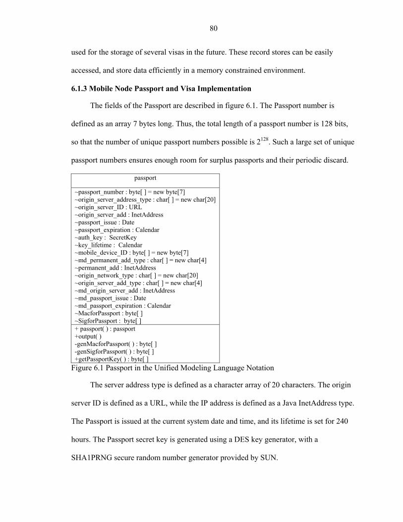
80
used for the storage of several visas in the future. These record stores can be easily
accessed, and store data efficiently in a memory constrained environment.
6.1.3 Mobile Node Passport and Visa Implementation
The fields of the Passport are described in figure 6.1. The Passport number is
defined as an array 7 bytes long. Thus, the total length of a passport number is 128 bits,
so that the number of unique passport numbers possible is 2128. Such a large set of unique
passport numbers ensures enough room for surplus passports and their periodic discard.
passport
~passport_number : byte[ ] = new byte[7] ~origin_server_address_type : char[ ] = new char[20] ~origin_server_ID : URL ~origin_server_add : InetAddress ~passport_issue : Date ~passport_expiration : Calendar ~auth_key : SecretKey ~key_lifetime : Calendar ~mobile_device_ID : byte[ ] = new byte[7] ~md_permanent_add_type : char[ ] = new char[4] ~permanent_add : InetAddress ~origin_network_type : char[ ] = new char[20] ~origin_server_add_type : char[ ] = new char[4] ~md_origin_server_add : InetAddress ~md_passport_issue : Date ~md_passport_expiration : Calendar ~MacforPassport : byte[ ] ~SigforPassport : byte[ ] + passport( ) : passport +output( ) -genMacforPassport( ) : byte[ ] -genSigforPassport( ) : byte[ ] +getPassportKey( ) : byte[ ]
Figure 6.1 Passport in the Unified Modeling Language Notation
The server address type is defined as a character array of 20 characters. The origin
server ID is defined as a URL, while the IP address is defined as a Java InetAddress type.
The Passport is issued at the current system date and time, and its lifetime is set for 240
hours. The Passport secret key is generated using a DES key generator, with a
SHA1PRNG secure random number generator provided by SUN.

81
The mobile device ID is a 7 byte array, providing enough leeway for surplus
mobile device IDs. Its network type and server address type is a 4 character array and the
permanent address is defined as a Java InetAddress. The mobile device is issued the
passport at a system date and time, with a lifetime currently set at 240 hours.
Once the passport details are assigned, a MAC is computed using an instance of the
HmacMD5 key generator. After this a digital signature identifying the server issuing the
passport is generated. The Digital Signature Algorithm (DSA) in conjunction with a
SHA1PRNG secure Random number generator is used to generate the signature, where
the entire passport is used as a source.
Figure 6.2 Visa in the Unified Modeling Language Notation
visa
~visa_number : byte[ ] = new byte[7] ~visa_issue : Date ~visa_expiration : Calendar ~system_network_type : char[ ] = new char[20] ~server_add_type : char[ ] = new char[4] ~server_add : InetAddress ~multiple_entries : Boolean ~auth_key : SecretKey ~key_lifetime : Calendar ~MacforVisa : byte[ ] ~SigforVisa : byte[ ] +visa( ) : visa +output( ) -genMacforVisa( ) : byte[ ] -genSigforVisa( ) : byte[ ] +getVisaKey( ) : byte[ ]
The mobile node visa fields are shown in figure 6.2. The visa number is a 7 byte
array, the network type is a 20 character array, and the server address type is a 4 character
array. The visa has a special field for enabling multiple network re-entries, which is
defined as a Boolean variable. If it is set, the visa is valid for multiple authentications,
otherwise, it is only valid for a single authentication. A MAC and a digital signature are
also generated for the visa using the same algorithms as those used for the passport.

82
6.1.4 Visa Centre Implementation
Figure 6.3 depicts the Visa Centre as designed in the prototype in UML format.
The class mobileServerThread represents the Visa Centre. It accepts connections from
clients that have much less processing power as those found in the wireless environment.
mobileServerThread
-mtSocket : Socket = null -responseID : int=0 -challenge : int -mobileID : int -mt_hello_state : char = ‘1’ -vc_hello_full_state : char = ‘2’ -vc_hello_partial_state : char = ‘3’ -vc_respons_state : char = ‘4’ -pnv_state : char = ‘5’ -ch_respons_state : char = ‘6’ -stateArray : String[ ] = {“mt_hello”, “vc_hello_full”, “vc_hello_partial”, “pnv”, “ch_respons”} +mobileServerThread(socket : Socket, fserver : fileserver ) : mobileServerThread +run( )
Figure 6.3 Visa Centre in the Unified Modeling Language Notation
This server accepts a client connection, and also accepts an instance of the
fileserver. It then performs the following functions:
• Accepts connections with a mobile client which cannot process serializable data. Hence, all data must be of basic data types.
• Interacts with the fileserver, which is the repository for mobile node data and authenticates the mobile terminal.
• Accepts the mobile node’s response ID, and compares it with previously stored values if any.
• Updates the response ID with the fileserver.
• Decodes the passport and visa returned by the mobile terminal.
• Generates a challenge to be used for the challenge response. Generation of a challenge response algorithm is currently beyond the scope of this prototype. Note that no secret key is generated and transmitted to the mobile terminal, since the mobile node lacks the processing power to generate encrypted data. All information in the mobile terminal is pre-processed, encrypted and compressed.

83
6.1.4.1 Handshake mechanisms
The run function in figures 6.3 performs the visa handshake mechanisms. Both the
full handshake and the partial handshake are implemented. Data are accepted as simple
data streams. Each state is identified by a character assigned to it. As long as the states
are according to the visa handshake states, the while loop runs. When the data received is
incongruous, the while loop breaks, and the server closes the connection. The loop breaks
naturally when the final state of the handshake are reached.
6.1.4.2 Authentication mechanisms
fileserver
+fileserver( ) : fileserver +createEntry( in mobileID : int) +update(in mobileID : int, in responseID : int) +authenticate(in mobileID : int, in responseID : int) : int +close( )
Figure 6.4 Authentication Module in the UML Notation
The Visa Centre performs authentication in collusion with a backend authentication
database. This database holds all the information pertaining to a mobile terminal.
Comparisons are made against this database for approving mobile node IDs and response
IDs. When a mobile node first accesses the visa centre, an entry is for the mobile node is
created in the database. This entry is identified via the mobile node ID, and includes a
field for the visa center generated response ID. The response ID is updated during each
handshake. Figure 6.4 describes the authentication module. This module is called the
fileserver.
When authenticating the mobile node during an abbreviated handshake three
possible events may occur. In the first case, a valid record exists for the mobile ID and
the corresponding response ID. In this case the abbreviated handshake ensues. In the

84
second case, a record for the mobile node ID exists, but the response ID does not match.
In this case, the visa centre requests a full handshake. In the third case, a record for the
mobile node ID is not available. Network access is denied in this case.
6.1.5 Mobile Node Implementation
client
-mt_hello_state : char = ‘1’ -vc_hello_full_state : char = ‘2’ -vc_hello_partial_state : char = ‘3’ -vc_respons_state : char = ‘4’ -pnv_state : char = ‘5’ -ch_respons_state : char = ‘6’ -stateArray : String[ ] = {“mt_hello”, “vc_hello_full”, “vc_hello_partial”, “pnv”, “ch_respons”} -ch_response : int -responseID : int - mobileID : int +client(m : socket_trialMidlet) : client +start ( ) + stop( ) + commandAction( ) +run( ) -clientHandshake( )
Figure 6.5 Mobile Node in the UML Notation
Figure 6.5 describes the mobile node as the client. This class implements the
mobile client as seen in a typical wireless environment. The input is the chief midlet that
is started at the beginning of the application. It creates a mobileID that identifies the
mobile node uniquely, and remains constant for the lifetime of the mobile node. The class
reads the encrypted and compressed passport and visa from a file that emulates the
existance of a SIM card. It also assigns the default responseID to 0.
This method implements the client side VISA protocol. It calls the client method
that performs the handshake. It first opens a client side socket using the server port
number. Since in this case, the server runs on the local host, the server URL is localhost.
The input and output streams are simple data streams, and all input and output are in the
form of basic data types.

85
The prototype was run using the Wireless ToolKit available in J2ME. Several
results were collected from this execution, describing the memory usage, the function call
graph and most importantly the nature of the network packets. These outputs were used
as inputs to the simulation of the protocol. The simulation parameters, process and results
are described next.
6.2 OPNET Simulation
OPNET is a network simulation software package with an extensive set of features
designed to support general network modeling and to provide specific support for
particular types of network simulation projects. It provides a comprehensive development
environment supporting the modeling of communication networks and distributed
systems. Both behavior and performance of modeled systems can be analyzed by
performing discrete event simulations.
The OPNET environment incorporates tools for all phases of a study, including
model design, simulation, data collection, and data analysis and also provides a flexible,
high-level programming language with extensive support for communications and
distributed systems. This environment allows realistic modeling of all communications
protocols, algorithms, and transmission technologies. OPNET also has representations for
several applications, including Remote Login, Secure Sockets Layer (SSL), Web Server
and Database Servers.

86
6.2.1 Simulation Architecture
Figure 6.6 Office Enterprise Topology
Figure 6.6 describes the OPNET office enterprise architecture used for simulating
the visa protocol. The simulation uses four office buildings, each containing a single
wireless LAN and is each represented by one subnet. Each subnets is connected to a
dedicated router in the wireline distribution system as shown in the figure.
The routers are Ethernet slip gateways, running on a single processor. Each subnet
has a wireless access point that serves all of the resident mobile nodes. The access point
is a WLAN Ethernet router (wlan_ethernet_router_adv) running on a single processor. It
has the IP Gateway Function enabled with OPNET default Ethernet parameters, IGMP
and TCP parameters. The WLAN has a data rate of 1 MBps with frequency hopping

87
spread spectrum physical characteristics and has a receive lifetime of 0.5 seconds and
drops large packets.
The enterprise architecture is supported by two servers configured as visa centers.
These centers are located in office buildings 1 and 2 and each is a WLAN server
(wlan_server_adv) running on a SUN Ultra 10 333 MHz simple CPU. Each server’s
supported application services includes the full handshake and the abbreviated
handshake. Each of the servers can be accessed by the mobile terminals with equal
probability.
Figure 6.7 Office Building Subnet
Figure 6.7 shows the wireless LAN subnet, which supports 20 mobile nodes. Each
terminal is a WLAN workstation (wlan_wkstn_adv) that supports the VISA protocol, and
provides the functionality of the mobile terminal. When the simulation is run, each
workstation randomly picks one of the two visa centers and attempts to initiate an
authentication. Each workstation can initiate more than one authentication, representing a
user that has left the network and later returned. Thus, both full handshake and

88
abbreviated handshake attempts must be executed, depending on the time period between
attempts
6.2.2 The Custom Application Model
As mentioned previously, the VISA protocol is represented in a two-tier manner, in
a client server application, where the mobile nodes function as the client, and the visa
centre functions as the server. An OPNET custom application was designed based on the
VISA protocol.
A custom application comprised of a hierarchy of objects. At the bottom of the
hierarchy is the task, which is a basic unit of user activity within the context of the
application. Included in a task is a phase, which is an interval of related activity, e.g. a
data transfer process. A task specification is a table that describes the sequence of phases
and steps involved in a task. The next step in the hierarchy is an application. The
application epitomizes a software product that is used to perform a task. At the top of the
hierarchy lies the profile definition. The profile determines the manner of execution of
the application, and on which objects it is executed.
Each handshake mechanism was classified as a task. Within the task, each of the
steps in the handshake was configured as a phase of the task. So, for the full handshake,
the phases were the mobile device hello, the server hello for a full handshake, the transfer
of the passport and the visa and the server response. The configuration was carried out
manually, with each phase starting when the previous phase ended. No timeout properties
were used, and the default transport connection provided by OPNET was used.
The source-to-destination traffic was modeled as presented in Table 6.1. The
Request Packet Size was a major factor in the network traffic. It was dependent on the

89
data being transmitted over the network for a particular phase. The amount of data being
transmitted for each phase was determined via the Java implementation of the protocol.
Table 6.1 Traffic Modeling in OPNET *Variable Attribute Value Initialization Time(seconds)
Constant(0)
Request Count Constant(1) Interrequest Time(seconds)
Exponential(1.0)
Request Packet Size* (bytes)
Constant(6)
Packets per Request (bytes)
Constant(1)
Once the tasks were generated the application was defined which included an
instances of the full handshake and the abbreviated handshake. The full handshake had a
serial task ordering, TCP transport protocol, best effort type of service and a refresh
connection after every phase. The abbreviated handshake concurrent task ordering, TCP
transport connection and best effort type of service which included delay, throughput and
reliability. The abbreviated handshake connection was refreshed after every phase.
Thereafter a profile definition object was generated. Each profile operated in serial
order, starting uniformly with a minimum outcome of 100 and a maximum outcome of
110. Each profile ran through the end of the simulation. Each application repeated itself
in an unlimited manner as the requests were submitted randomly from the mobile node to
the visa centers.
The VISA protocol was compared with OPNET’s secure sockets layer (SSL)
application. SSL has become the de facto standard for secure communications between
end users and Internet sites, and today, SSL support is built into virtually every browser.

90
The SSL protocol includes two subprotocols - the SSL handshake protocol and the
SSL record protocol. Both provide authenticated, confidential and tamper-resistant
connections to applications, particularly HTTP. SSL's footprint fits into the Internet's
processing stack, above TCP/IP and below the application layer without significantly
affecting the other protocol layers. OPNET’s SSL application simulates the SSL
Handshake protocol which authenticates the client and the server. The messages involved
authenticate the server and the client to each other, allow the client and the server to
select cryptographic algorithms and the level of security that they want and use public
key cryptography to generate shared secret keys that will be used later to transmit data
securely. Thus the messages involved in the handshake are:
• Server hello • Server certificate • Client certificate request • Server hello done • Client change cipher spec • Client certificate • Certificate verified • Client key exchange • Client finished • Server change cipher spec • Server finished
The OPNET SSL application was modeled so that it only represented the header
fields of each packet sent, and not the payload. In the presence of the payload which
would be considerable in SSL given the amount of certificate passing, the results from
the simulation would have been very favorable to the full handshake application.
However, it was decided that in this scenario, a worst case analysis is preferred; hence the
SSL application was used without any payload. The outputs from the Java
implementation of the VISA protocol were used as inputs to the OPNET simulation

91
parameters above. Then the simulation was run for an hour to observe the performance of
the VISA protocol with respect to signaling load and processing delay.
6.3 Java Emulation Performance Results
The first set of results shows the bandwidth consumed during the execution of the
different handshake messages.
Table 6.2 Full Handshake Action Bytes
Mobile Terminal Hello 10 Server Full Handshake Hello 10
Passport and Visa from Mobile Terminal
3094
Server Response 6 The network monitor results are tabulated in Tables 6.2 and 6.3. It can be seen that
the full handshake requires a much larger bandwidth than the abbreviated handshake.
Table 6.3 Abbreviated Handshake Action Bytes Mobile Terminal Hello 10 Server Partial Handshake Hello
6
Mobile Terminal Challenge Response
6
Server Response 6
Figure 6.8 provides a snapshot of the network monitor results during a full
handshake. The particular network packet shown contains the mobile node passport and
visa in an encrypted form. The snapshot reveals that socket communication was used. It
also shows that the prototype was run three times. The first run was a full handshake,
while the second and third runs used the abbreviated handshake.

92
Figure 6.8 A Snapshot of the Network Monitor Results
The results from the memory monitor are described in Figure 6.9.
Figure 6.9 Memory Monitor Results
These results become important when the device implementing the VISA protocol
is a wireless mobile device such as a cellular phone or a PDA. The memory and
processing power available on such a device is constrained, and it has to be ensured that
the demands made by the protocol do not overwhelm the device.

93
Figure 6.10 Function Call Graph
Figure 6.10 gives a snapshot of the function call graph, captured during program
execution. The methods called by the application are seen, as well as the percentage of
time that each process used
While the prototype provided significant results, it could not determine how VISA
would compare to other application protocols in the wireless environment. Thus network
monitor results were compared against other contemporary protocols using the OPNET
Modeler software. The next two sections describe the simulation results.
6.4 OPNET Simulation Performance Results
6.4.1 Analysis of VISA Handshake Mechanisms
This section analyses the full handshake and abbreviated handshake mechanism
closely. Each handshake mechanism was modeled separately, the expected network data
compared with the observed results.

94
6.4.1.1Analysis of full handshake
The full handshake was modeled using the Java implementation results obtained in
tables 6.2 and 6.3. This section looks at the individual phases of the full handshake task,
and the source to destination data in particular. The source to destination data was
defined as follows
• Request Count = number of requests • Packet size • Number of packets per request • Therefore, size of a request = number of packets per request*Packet size • Total data to be transmitted per phase = Request Count*size of a request
The request count was 1, number of packets per request was 1 and the packet size
was determined according to table 6.2. In the realm of the client-server configuration we
get,
Total network data sent = 10+3094 = 3104 bytes
Total network data received = 16 bytes
Total network load = 3120 bytes
Data rate of the wireless LAN = 1 Mbps
Total transmission time over the network =
Total network load/data rate of the wireless LAN =
3120 bytes/1Mbps = 0.025 seconds.
However, these calculations do not include background link traffic, TCP overhead
and WLAN overhead.
The application was simulated to see the actual load and time taken by the
application to run. The simulation results described below were for a single server
interacting with a single client. The Full Handshake application was run once. The
simulation was run for a total of three minutes. The application by scheduled to start 20

95
seconds into the simulation, and it was scheduled to run for 30 seconds. The results are
summarized as follows.
Application details. The first set of results describes the parameters related to the
application. The traffic generated by the application can be categorized as the traffic
received, which is traffic from the visa centre to the mobile node, and the traffic sent,
which is the traffic from the mobile node to the visa centre.
Table 6.4 Full Handshake Application Statistics
Statistic Average Maximum Minimum
Traffic Received (bytes/sec) 0.2 12.2 0.0
Traffic Sent (bytes/sec) 17 1,670 0
The graphs for these statistics are described in figures 6.11 and 6.12. The
application traffic received in figure 6.11 corresponds to two phases of the full
handshake. These are the visa centre hello, and the final response ID from the visa centre.
They are illustrated in rows 2 and 4 of table 6.2. The graph reflects the packet sizes
required for these two phases.
Figure 6.11 Application Traffic Received (Full Handshake)

96
The area under the graph describes the total number of bytes received, and is
illustrated as ½(base*height), where height = 12.2 bytes per second (from table 6.4) and
base is approximately equal to 3 seconds.
Figure 6.12 Application Traffic Sent (Full Handshake)
The traffic sent corresponds to the traffic sent from the mobile terminal to the visa
centre. This packet sizes for the traffic corresponds to two phases in the full handshake:
the mobile node hello phase and the passport and visa transmission phase, which are
illustrated in rows 1 and 3 of table 6.2.
The area under the graph results in the total bytes of data sent, and is illustrated as
½(base*height), where height = 1670 bytes per second (from table 6.4) and base is
approximately equal to 3.5 seconds. This result equals 3100 bytes, or the sum of the
packet sizes corresponding to the phases sending data from the mobile terminal.
The next set of results describes the effects of the application on the wireless LAN,
which is our network.

97
From table 6.5, we can determine that no data was dropped. Hence, we can assume,
that network load was not generated by the mobile node resending any of the packets.
The absolute value of the wireless LAN load is illustrated in figure 6.13, while the
average delay is illustrated in figure 6.14.
Table 6.5 Wireless LAN Statistics (Full Handshake)
Statistic Average Maximum Minimum
Wireless LAN Data Dropped (bits/sec) 0 0 0
Wireless LAN Delay (sec) 0.0061 0.0303 0.0002
Wireless LAN Load (bits/sec) 467 22,738 0
Wireless LAN Throughput (bits/sec) 276 11,369 0
To further understand the working of the simulation, the graph illustrated in figure
6.13 was exported onto a spreadsheet and the relevant results are illustrated in table 6.6.
A further analysis of the graph showed that the total network load in terms of raw data
was 46257 bits.
Figure 6.13 Wireless LAN Load (Full Handshake)
However, the simulation was designed so that the application began at 5 seconds
and terminated at 30 seconds.

98
Table 6.6 Wireless LAN Load (Full Handshake) time (sec) Wireless LAN.Load (bits/sec).
0 0 1.8 0 3.6 8515.556 5.4 22737.78 7.2 1760
9 2328.889 10.8 497.7778 12.6 1386.667 14.4 1351.111 16.2 0
18 0 19.8 0 21.6 0 23.4 0 25.2 0
27 0 28.8 0 30.6 0 32.4 0 34.2 7680 36.0 0 25.2 0
It can be seen that the remaining bits causing network load did not originate from
the full handshake application. The resulting raw network load is thus 30062 bits. The
total overhead that is thus incurred by the protocol is the difference between the actual
network load, and the estimated network load, which is 5102 bits or 20% of the estimated
network load.
Figure 6.14 illustrates the average delay experienced by the application. Table 6.5
illustrates the wireless LAN characteristics, with a maximum delay of 0.0303 seconds,
and an average delay of 0.0061 seconds.
The total delay can be calculates as average delay*total time over simulation =
0.0061*180 = 1.098 seconds.
The total time taken for the application is the sum of the processing time for
individual phases of the application, data transmission time, delay and other overheads
like TCP ack time. It is seen, that it takes about 30 seconds for the application to run.

99
Figure 6.14 WLAN Average Delay (Full Handshake)
In the next section, a similar analysis is performed on the abbreviated handshake.
6.4.1.2 Abbreviated handshake analysis
The abbreviated handshake is considerably light when compared to the full
handshake. Table 6.3 describes the packet sizes used in this application. In the realm of
the client-server configuration we get,
Total network data sent = 6+6 = 12 bytes
Total network data received = 12 bytes
Total network load = 24 bytes
Data rate of the wireless LAN = 1 Mbps
Total transmission time over the network = Total network load/data rate of the wireless LAN = 24 bytes/1Mbps = 0.000192 seconds.
However, these calculations do not include background link traffic, TCP overhead
and WLAN overhead. The abbreviated handshake was also simulated as a stand-alone
application. The simulation comprised a single server, a single mobile node and the

100
abbreviated handshake was performed once. Figure 6.15 illustrates the data sent and
received.
Figure 6.15 Abbreviated Handshake Data Sent and Received
The first graph illustrates the data sent from the mobile node to the visa centre and
the second graph illustrates the data sent from the visa centre to the mobile node.
These data correspond to the data sent and received as calculated earlier.
Figure 6.16 Average Network Load
Figure 6.16 and table 6.7 summarize the network load properties after running the
abbreviated handshake. The network experiences an average load of 245 bits per second
and a maximum of 7,680 bits per second. Like in the case of the full handshake, the
actual time taken for the abbreviated handshake is considerably larger than the estimated

101
calculated. Overheads, actual processing time and TCP acks are some of the reasons for
the time taken.
Table 6.7 Wireless LAN Statistics
Statistic Average Maximum Minimum
Wireless LAN Data Dropped (bits/sec) 0 0 0
Wireless LAN Load (bits/sec) 245 7,680 0
The above analysis provided a better insight about the protocol and the various
parameters involved. The next section describes the results obtained from the OPNET
simulation when it was run to compare the VISA protocol with the SSL application.
6.4.2 Simulation Results
The protocol has been compared against the OPNET SSL protocol. The results for
network load and delay generated by the VISA protocol were compared against that
generated by the SSL Application, and the results are graphed in the figures below. The
Full Handshake and the Abbreviated Handshake are compared separately with the SSL
Application.

102
Abbreviated Handshake Traffic Sent (bytes/sec)
SSL Handshake Traffic Sent (bytes/sec)
Full Handshake Traffic Sent (bytes/sec)
Figure 6.17 Application Traffic Sent
Figure 6.17 illustrates the application traffic sent by each application. The first
graph describes the Abbreviated Handshake, the second graph describes the SSL
application and the third graph describes the full handshake.
Table 6.8 Comparison Chart for Traffic Sent
Statistic Average Maximum Minimum
Abbreviated Handshake: Traffic Sent (bytes/sec) 2.04 7.00 0.00
SSL Handshake: Traffic Sent (bytes/sec) 6.3 14.2 0.0
Full Handshake: Traffic Sent (bytes/sec) 164 938 0
Table 6.8 summarizes the statistics represented in the figure 6.17. The traffic sent
by the full handshake application is quite significant when compared to the SSL

103
application. It is also visible, that the maximum bytes of data sent at a time in the full
handshake differ from the snapshot in figure 6.12. This is attributed to the fact that now
several nodes are sending data at a time, and there are several issues to be considered,
like buffer size limits at the server and network access issues.
Abbreviated Handshake Traffic Received (bytes/sec)
SSL Handshake Traffic Received (bytes/sec)
Full Handshake Traffic Received (bytes/sec)
Figure 6.18 Traffic Received
Figure 6.18 describes the traffic received by the mobile node for each application.
The first graph illustrates the abbreviated handshake, the second graph illustrates the SSL
application and the third graph illustrates the full handshake. Table 6.9 summarizes the
results from figure 6.18. The VISA Applications have a small amount of traffic received,
while the SSL handshake sends and receives comparatively larger amounts of traffic.

104
Table 6.9 Comparison Chart for Traffic Received
Statistic Average Maximum Minimum
Abbreviated Handshake: Traffic Received (bytes/sec)
1.01 5.33 0.00
SSL Handshake: Traffic Received (bytes/sec) 3.0 10.9 0.0
Full Handshake: Traffic Received (bytes/sec) 0.82 4.67 0
The next set of figures illustrates the network load experienced by the wireless
LAN in each circumstance.
Abbreviated Handshake Load (bits/sec)
SSL Handshake Load (bits/sec)
Full Handshake Load (bits/sec)
Figure 6.19 Average Network Load
The wireless LAN network load has been represented as average load to illustrate
the load experienced over the network throughout the entire simulation, versus just at

105
specific points in time. The load defined in bits per second generalizes the average load at
that point in time.
Table 6.10 Comparison Chart for Network Load
Statistic Average Maximum Minimum
Abbreviated Handshake: Load (bits/sec) 194 839 0
SSL Handshake: Load (bits/sec) 2,436 5,673 0
Full Handshake: Load (bits/sec) 1,570 8,908 0
Table 6.10 summarizes the results from figure 6.19. The network load for the full
handshake application compares with the OPNET SSL application. However, the results
from the abbreviated handshake very well compensate for the full handshake.
The results obtained from the prototype implementation and the OPNET simulation
suggests that VISA can be deployed on a wireless network in a feasible manner. While
the Full Handshake does require considerable bandwidth, the Abbreviated Handshake
more than makes up for it, with its low bandwidth requirements.

CHAPTER 7 CONCLUSIONS
The nature of wireless communication is becoming highly distributed, with users
and service providers choosing to inter-operate as their data service and business needs
require. New mechanisms are needed to allow service providers to interoperate in order
to validate unknown users that enter a network. This paper provided an option for the
creation of a mobile node passport and visa, which can be used for this purpose. The
entities and procedures were outlined, and several performance measurements were
made, according to the load generated by the new mechanisms, as well as the delays
incurred. It was demonstrated that the passport and visa, full and abbreviated handshake
have load demands and delays comparable to common applications, such as a remote
login operation. Information and modules resulting from the OPNET simulation study are
available at the following website: http://www.wam.ece.ufl.edu/visa.
Future work
The VISA focuses on the structure of the passport and visa, the rules for obtaining
the passport and the visa and the Full and Abbreviated Handshake that are required for
ensuring proper identification and authentication of the mobile node. However, there are
some areas that still need to be developed, including Key Management, Server
Management and Authorization and Accounting.
Key management. It has been seen in the abbreviated handshake that the passport
and visa authentication keys assume significant importance. The passport and the visa
also stimulate the keys with sufficient details relating to their lifetime. However, nothing
106

107
has been specified clearly yet about the refreshing of keys. There are several questions in
the area of key management that are unanswered. Significant among these are how would
the refreshed keys be made available to a mobile node, what happens when a passport
authentication key expires when a mobile node is not in its home network but in a foreign
network and when would a mobile node receive a refreshed visa authentication key?
It can be suggested that the passport authentication key only be made available
when the mobile node is its own network. A similar approach could be adopted when
refreshing visa authentication keys. This kind of an approach would then require a server
initiated messages, which is now possible in the Diameter AAA Protocol.
Server management. The current VISA protocol assumes that servers would
easily incorporate the protocol. However, this is not as simple as it appears. VISA has
been designed keeping in mind AAA servers like RADIUS and Diameter. However, it is
yet to be integrated into the AAA protocols. One requirement for its actual
implementation in the future would be its integration. Another aspect that VISA relies on
is inter-system communication between servers. While this exists to some extent, it has to
be fine tuned for obtaining the Visa for the Mobile Node and other related background
signaling. VISA currently defines the PDUs for this purpose, but it is yet to be seen how
these PDUs would fit in the real world.
Accounting. The Passport and the Visa have provided a lot of room for
improvement for accounting and authorization services. The account ID and
Authorization information as well as information about the billing records indicate that
there is provision for working in this direction. Future work would entail determing some
kind of a billing policy and associating the Account ID and hence the mobile node with a

108
billing server. Also, a Visa could be multi-purpose in future. It could be associated with a
set of authorization rules for the mobile node. This would clearly state what resources the
mobile node may access and what resources the mobile node may not in the foreign
network.

LIST OF REFERENCES
1. T.S. Rappaport, A. Annamalai, R.M. Buehrer, and W.H. Tranter, “Wireless Communications: Past Events and a Future Perspective,” IEEE Communications Magazine: 50th Anniversary Commemorative Issue, pp. 148–161, May 2002.
2. W. Stallings, Cryptography and Network Security, Second Edition, Prentice Hall, Upper Saddle River, NJ.
3. The Internet Engineering Task Force, Authentication, Authorization and Accounting Working Group, September 29th 2003, http://www.ietf.org/html.charters/aaa-charter.html, October 5th 2003.
4. B. Lloyd, W. Simpson, Point to Point Protocol Authentication Protocols. RFC 1334, 1992, http://www.ietf.org/rfc/rfc1334.txt, October 5th 2003.
5. W. Simpson, Challenge Handshake Authentication Protocol, CHAP, RFC 1994, 1994, http://www.ietf.org/rfc/rfc1994.txt, October 5th 2003
6. D. Estrin, J. Mogul and G. Tsudik, “Visa Protocols for Controlling Inter-Organizational Datagram Flow”, IEEE Journal on Selected Areas in Communications, Volume 7, Number 4, pp 486-497, May 1989.
7. O. Eksioglu, R. Newman and R. Chow, “The Design and Implementation of Packet-Level Access Control Security Scheme (PASS)”, Proceedings of the International Symposium of Internet Technology, pp 266-271, Taipei, Taiwan, April, 1998.
8. Vijaya Chandran Ramasami, “Security, Authentication and Access Control for Mobile Communications”,2001, http://www.ittc.ku.edu/~rvc/documents/865/865_securityreport.pdf, October 5th 2003
9. European Telecommunications Standards Institute European digital cellular telecommunications system (Phase 2); Radio network planning aspects, February 1995, http://www.etsi.org, October 5th 2003
10. Global System for Mobile Communication 01.02:Digital Cellular Telecommunications System (Phase 2+), General Description of a Public Land Mobile Network (PLMN), ETSI Technical Report, October 1993.
109

110
11. Global System for Mobile Communication 02.17:Digital Cellular Telecommunications System (Phase 2+), Subscriber Identity Modules, Functional Characteristics, ETSI Technical Report 1998.
12. Global System for Mobile Communication 02.07:Digital Cellular Telecommunications System (Phase 2+), Mobile Station (MS) features, ETSI Technical Report 1998.
13. Global System for Mobile Communication 11.11: Digital Cellular Telecommunications System (Phase 2+), Specification of the Subscriber Identity Module - Mobile Equipment (SIM-ME) Interface, Sophia Antipolis, France, 1998.
14. Third Generation Partnership Project, Technical Specification Group Services and System Aspects, International Mobile station Equipment Identities (IMEI), Release 1999.
15. Global System for Mobile Communication 02.09: Digital Cellular Telecommunications System (Phase 2+), Security Aspects, June 1993.
16. Global System for Mobile Communication 03.20: Digital Cellular Telecommunications System (Phase 2+), Security Related Network Functions, Version 7.0.0., Release 1998.
17. Third Generation Partnership Project (3GPP), Release 99 Specifications, December 1999, http://www.3gpp.org/ftp/Specs/December_99/, October 5th 2003.
18. Universal Mobile Telecommunication System (UMTS) 23.01, UMTS Network Architecture, Version 0.2.0, November 1997.
19. 3G TS 21.133, 3rd Generation Partnership Project; Technical Specification Group (TSG); 3G Security, Security Threats and Requirements, Version 3.1.0, 1999.
20. 3G TS 33.102, 3rd Generation Partnership Project; Technical Specification Group (TSG),3G Security; Security Architecture, 1999.
21. 3G TS 33.120, 3rd Generation Partnership Project; Technical Specification Group (TSG), 3G Security; Security Principles and Objectives, 1999.
22. 3G TS 33.900, 3rd Generation Partnership Project; Technical Specification Group (TSG), A Guide to 3rd Generation Security, Version 1.2.0, 2000.
23. Global System for Mobile Communication 02.22, Personalization of GSM Mobile Equipment (ME); Mobile Functionality Specification, Version 6.0.0.
24. Global System for Mobile Communication 09.02, Mobile Application Part (MAP) Specification, Version 4.8.0, Technical Report, 1994.

111
25. S. Weatherspoon, “Overview of IEEE 802.11b Security”, http://www.intel.com/technology/itj/q22000/articles/art_5.htm, Network Communication, Intel Technology, October 5th 2003.
26. J. Williams, “The IEEE 802.11b Security Problem”, IT Professional, Nov/Dec 2001, pp 96
27. C. Metz, “AAA Protocols: Authentication, Authorization, and Accounting for the Internet”, Internet Computing, IEEE , Vol. 3, Issue 6 , Nov.-Dec. 1999 Page(s): 75 -79
28. C. Perkins, Mobile Networking through Mobile IP, IEEE Internet Computing, Vol. 2, No. 1, Jan 1998, pp 5869.
29. C. Perkins, “IP Mobility Support” IETF RFC 2002, Oct.1996.
30. C Perkins, “Mobile IP” IEEE Comm., Vol. 35, No. 5, 1997, pp 84-99.
31. C. Perkins, “Mobile IP joins Forces with AAA”, IEEE Personal Communications, Vol. 7, No. 4, Aug 2000, pp 59-61.
32. N. El-Fishway, M. Nofal, A Tadros, “An Effective Approach for Authentication of Mobile Users” IEEE 55th Vehicular Technology Conference, 2002, Vol. 2, Mar 2002, pp 598 -601.
33. K. Hwang; C. Chang; “A Self-Encryption Mechanism for Authentication of Roaming and Teleconference services” IEEE Transactions on Wireless Communications, Vol. 2, Issue 2 , Mar 2003, pp 400 -407.
34. A. Bharathan, J. McNair, “An OPNET Modeler Study of the Visa Mechanism for Multi-Network Authentication”, in Proc. of OPNETWORK 2003, Washington, D.C., August 2003, pp 94.
35. A. Bharathan, J. McNair, “VISA: An AdVanced Inter-System Authentication Protocol for Wireless Networks”, Submitted to Elsevier Computer Networks Journal, 2003.

BIOGRAPHICAL SKETCH
Aarti Bharathan is a graduate student in the Electrical and Computer Engineering
Department of the University of Florida. She graduates in December 2003 with a Master
of Science degree. Aarti has a bachelor’s degree in computer engineering from the
University of Mumbai, India, and has worked for a year with Wipro Technologies, India.
During her master’s study, Aarti has been a graduate research assistant at the
Wireless and Mobile Systems Laboratory, where she has conducted research on inter-
system authentication mechanisms for wireless environments.
112