intelligent unmanned air vehicle flight systemspersonal.psu.edu/lnl/papers/aiaa20057081.pdf ·...
TRANSCRIPT
American Institute of Aeronautics and Astronautics, InfoTech@Aerospace Conference, Paper No. 2005-7081
1
Intelligent Unmanned Air Vehicle Flight Systems
Jodi A. Miller*, Paul D. Minear*, and Albert F. Niessner, Jr.†
Applied Research Laboratory/The Pennsylvania State University, State College, PA, 16804
and
Anthony M. DeLullo‡, Brian R. Geiger‡, Lyle N. Long §, and Joseph F. Horn** The Pennsylvania State University, University Park, PA, 16802
This paper describes an intelligent autonomous airborne flight capability that is being used as a test bed for future technology development. The unmanned air vehicles (UAVs) fly under autonomous control of both an onboard computer and an autopilot. The onboard computer provides the mission control and runs the autonomous Intelligent Controller (IC) software while the autopilot controls the vehicle navigation and flight control. The autonomous airborne flight system is described in detail. An IC architecture directly applicable to the design of unmanned vehicles is also presented. The UAVs may operate independently or in cooperation with one another to carry out a specified mission. The intelligent UAV flight system is used to evaluate and study autonomous UAV control as well as multi-vehicle collaborative control.
I. Introduction Traditionally, unmanned air vehicles (UAVs) have been used to perform “dull, dirty, and dangerous” missions.
Military UAVs, such as Predator and Global Hawk, have demonstrated a reconnaissance and surveillance capability in such conflicts as Iraq, Bosnia, Kosovo, and Afghanistan. The Department of Defense described a roadmap for UAVs for the first quarter of the 21st century1. This roadmap cites two strong motivators for the continued development of Unmanned Air Systems: lower downside risk and higher confidence in mission success.
Intelligent control technologies are used to increase the autonomy of UAVs to a self-actualizing level. Some examples of approaches to intelligent systems are described in Refs. 2 – 4. While there is no universal consensus on how to define or measure an intelligent system, there are several characteristic traits that an intelligent controller might have, including: adaptability, learning capability, non-linearity, autonomous symbol interpretation, and goal-oriented and knowledge-based behaviors.5 As conceived for the Intelligent UAV Flight System described in this paper, an Intelligent Controller (IC) can be defined as one whose outputs are determined by employing input sensor data to build an internal representation of the external world, as opposed to using pre-established mathematical or model-based descriptions6.
Examples of intelligent control applications illustrate the variety of tasks capable of being performed. Johnson et al.7 have developed a UAV to enhance/augment human search capabilities by locating a specific building and identifying a possible opening into the building. Chalmers et al.8 have demonstrated swarm capabilities that are robust and resilient.
This paper describes an intelligent autonomous airborne flight capability (with operator override) that serves as a test bed for future technology development. “Autonomous” in this paper is defined as fully autonomous operations with human interactions as desired (versus remote piloting with human operations required). A commercially available autonomous autopilot is used to provide vehicle navigation and flight control stability for the unmanned air vehicle(s). An onboard computer running autonomous Intelligent Controller software provides mission control. Communications between these two systems provides the basis for the Intelligent UAV Flight System. This system was tested in a laboratory environment using a hardware-in-the-loop (HIL) simulation. Once tested on the ground, actual flight tests in the field were performed. * Research Faculty, Intelligent Control Systems, P.O. Box 30, AIAA Member. † Senior Research Associate, Emeritus, Guidance Systems Technology, P.O. Box 30. ‡ Graduate Assistant, Aerospace Engineering, 233 Hammond Building, AIAA Student Member. § Professor, Aerospace Engineering, 233 Hammond Building, AIAA Associate Fellow. ** Assistant Professor, Aerospace Engineering, 233 Hammond Building, AIAA Senior Member.
American Institute of Aeronautics and Astronautics, InfoTech@Aerospace Conference, Paper No. 2005-7081
2
II. Autonomous Airborne Flight System This section describes the flight system for the autonomous airborne flight capability. Radio controlled model
aircraft with commercially-developed autopilots, control processors, communications links, and sensors are used. The two major components of this system are the UAV and the ground base station along with their subsystems. When in use, the system is comprised of a single base station and multiple UAVs. Each UAV flies under the control of its onboard autopilot. The autopilot controls the vehicle navigation and flight control stability. An onboard computer, a single-board PC, running the Intelligent Controller (IC) software provides mission control. Manual control of the airborne units from the base station is available for takeoff and landing of the aircraft as well as providing limited safe operation in the event of component failure.
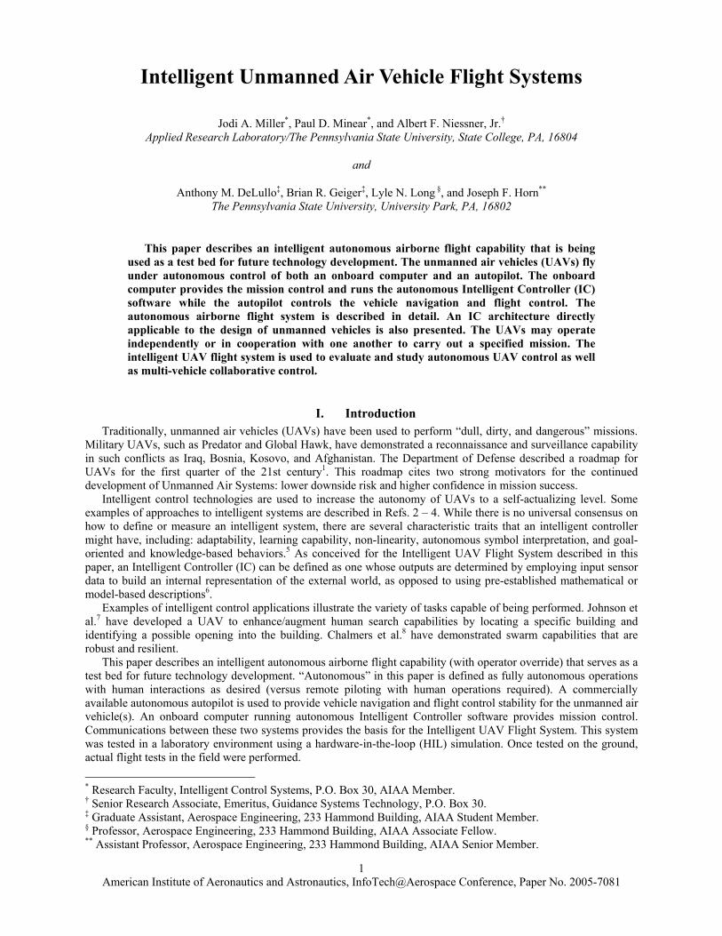
A. Operator Base Station The base station provides communications, flight control, telemetry recording, and flight visualization
between a human operator and each of the airborne units. As shown in Fig. 1, the base station is comprised of five hardware items.
Figure 1. Ground Base Station. The Cloud Cap Technology (CCT) Base Station, Pilot Console, and Operator Interface software are supplied as
part of Cloud Cap Technology’s Evaluation Kit. A laptop computer runs the Operator Interface software and the IC communications software. The Global Communications Transceiver is part of the network that allows mission communication among the system units. The Mobile Power Source provides the power needed to run the Base Station hardware in the field.
The Operator Interface is used to send commands to the airborne units and display the flight path and sensor data from the airborne units when they are within radio range. It also records all telemetry signals between the autopilot and the base station. In addition, all communications received by the IC are recorded for later playback.
The Pilot Console, a standard Radio Control (R/C) Transmitter modified to interface with the CCT Base Station, is used to manually control any one of the aircraft. Its primary use is taking off and landing the aircraft. Control of an aircraft by the Pilot Console is asserted by first selecting the aircraft’s communication channel on the operator interface, then using a switch on the pilot’s console to switch between the autopilot and manual mode of flight control.
The CCT Base Station has three communications systems. The GPS communications is for receiving GPS signals to obtain an accurate location of the base station. The second communications system uses a UHF transmitter
American Institute of Aeronautics and Astronautics, InfoTech@Aerospace Conference, Paper No. 2005-7081
3
and receiver for communicating with the aircraft autopilot. It is this radio channel that allows data to be sent to and received by the aircraft autopilot. The third communications system, an 802.11b ad-hoc network, is used to communicate with and among the IC processors.
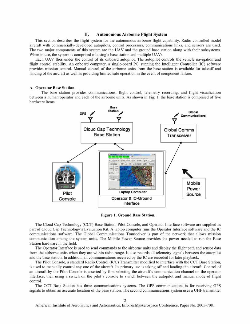
B. Airborne Platform The airborne platform is built around an R/C trainer class model airplane that is commercially available as an
Almost-Ready-to-Fly (ARF) aircraft. The model is a SIG Kadet Senior, an excellent trainer aircraft. Because of its stable flight characteristics and slow flying speed it is ideal for this testbed development effort. Figure 2 is a picture of the vehicle in a standard R/C configuration. This initial configuration was used to determine the suitability of this aircraft for the UAV application. The basic aircraft is made up of the airframe, engine, control servos, and an electrical power source. Table 1 lists the aircraft specifications.
The drive for the flight control surfaces are provided by standard Futaba servos. Electric power for the flight controls is obtained from a Nickel Metal Hydride (NiMH) battery pack. Use of the SIG Kadet model in this application required several modifications to the airframe. These modifications include the following:
1. Increased fuel capacity for extended flight times 2. Installation of heavy duty main and nose gear 3. Movement of the servos out of the central area of the fuselage 4. Installation of the autopilot and control processors 5. Installation of a pitot static tube mount 6. Installation of the GPS and communications antennas 7. Installation of a larger than normal engine
The required payload capacity is in excess of 5 pounds, including an extra large fuel tank (32 oz.) and mission
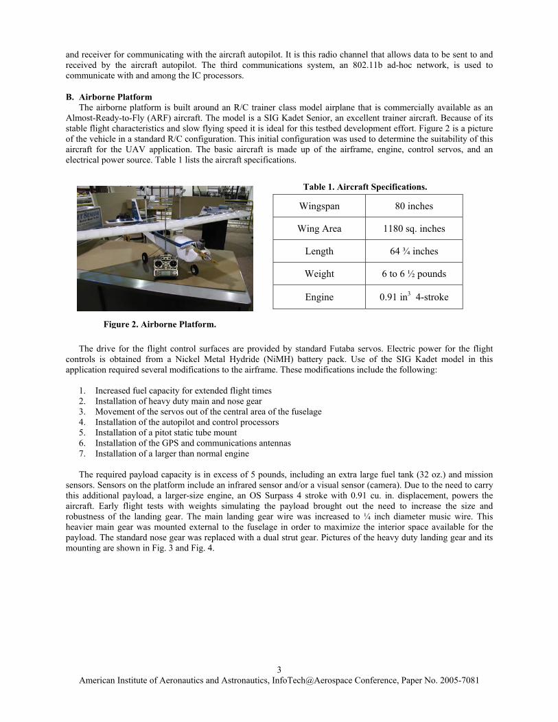
sensors. Sensors on the platform include an infrared sensor and/or a visual sensor (camera). Due to the need to carry this additional payload, a larger-size engine, an OS Surpass 4 stroke with 0.91 cu. in. displacement, powers the aircraft. Early flight tests with weights simulating the payload brought out the need to increase the size and robustness of the landing gear. The main landing gear wire was increased to ¼ inch diameter music wire. This heavier main gear was mounted external to the fuselage in order to maximize the interior space available for the payload. The standard nose gear was replaced with a dual strut gear. Pictures of the heavy duty landing gear and its mounting are shown in Fig. 3 and Fig. 4.
Wingspan 80 inches
Wing Area 1180 sq. inches
Length 64 ¾ inches
Weight 6 to 6 ½ pounds
Engine 0.91 in3 4-stroke
Table 1. Aircraft Specifications.
Figure 2. Airborne Platform.
American Institute of Aeronautics and Astronautics, InfoTech@Aerospace Conference, Paper No. 2005-7081
4
Figure 3. Heavy Duty External Mount Main Landing Gear. Figure 4. Heavy Duty Dual Strut Nose Gear. The engine servo and a heavy duty nose gear steering servo were moved to the front of the fuselage. The throttle
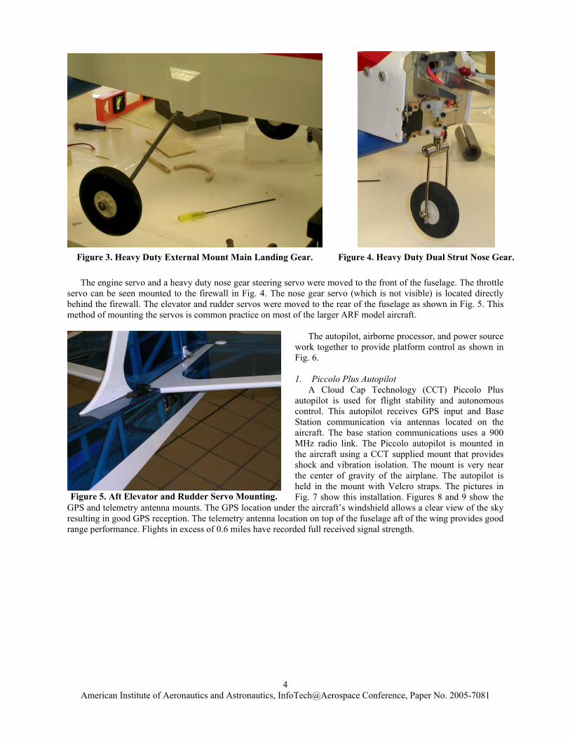
servo can be seen mounted to the firewall in Fig. 4. The nose gear servo (which is not visible) is located directly behind the firewall. The elevator and rudder servos were moved to the rear of the fuselage as shown in Fig. 5. This method of mounting the servos is common practice on most of the larger ARF model aircraft.
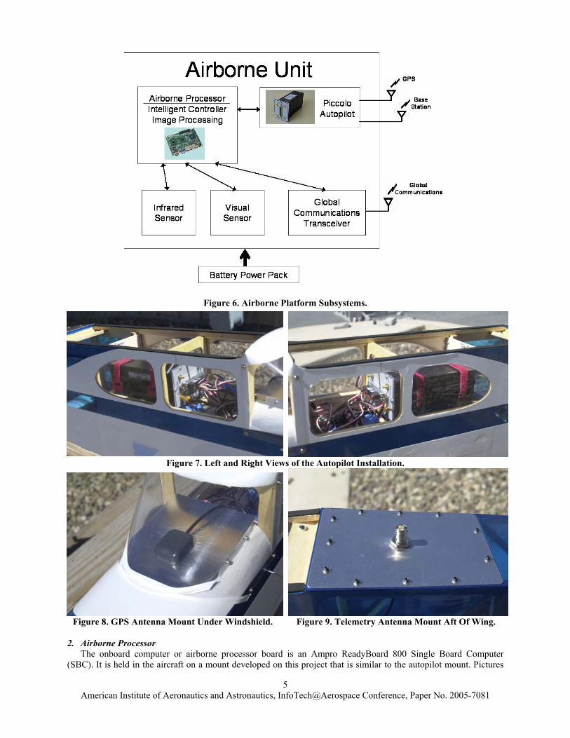
The autopilot, airborne processor, and power source
work together to provide platform control as shown in Fig. 6.
1. Piccolo Plus Autopilot
A Cloud Cap Technology (CCT) Piccolo Plus autopilot is used for flight stability and autonomous control. This autopilot receives GPS input and Base Station communication via antennas located on the aircraft. The base station communications uses a 900 MHz radio link. The Piccolo autopilot is mounted in the aircraft using a CCT supplied mount that provides shock and vibration isolation. The mount is very near the center of gravity of the airplane. The autopilot is held in the mount with Velcro straps. The pictures in Fig. 7 show this installation. Figures 8 and 9 show the
GPS and telemetry antenna mounts. The GPS location under the aircraft’s windshield allows a clear view of the sky resulting in good GPS reception. The telemetry antenna location on top of the fuselage aft of the wing provides good range performance. Flights in excess of 0.6 miles have recorded full received signal strength.
Figure 5. Aft Elevator and Rudder Servo Mounting.
American Institute of Aeronautics and Astronautics, InfoTech@Aerospace Conference, Paper No. 2005-7081
5
Figure 7. Left and Right Views of the Autopilot Installation.
Figure 8. GPS Antenna Mount Under Windshield. Figure 9. Telemetry Antenna Mount Aft Of Wing.
2. Airborne Processor The onboard computer or airborne processor board is an Ampro ReadyBoard 800 Single Board Computer
(SBC). It is held in the aircraft on a mount developed on this project that is similar to the autopilot mount. Pictures
Figure 6. Airborne Platform Subsystems.
American Institute of Aeronautics and Astronautics, InfoTech@Aerospace Conference, Paper No. 2005-7081
6
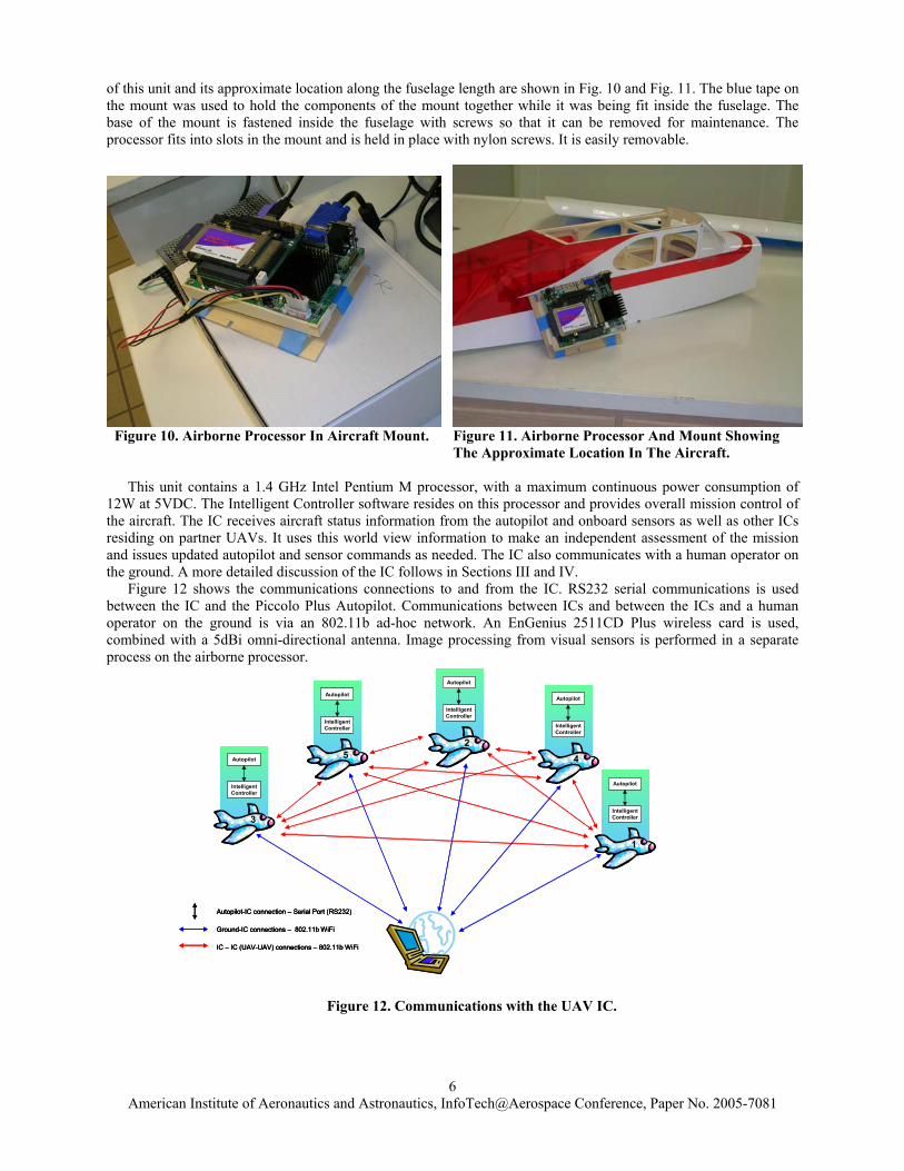
of this unit and its approximate location along the fuselage length are shown in Fig. 10 and Fig. 11. The blue tape on the mount was used to hold the components of the mount together while it was being fit inside the fuselage. The base of the mount is fastened inside the fuselage with screws so that it can be removed for maintenance. The processor fits into slots in the mount and is held in place with nylon screws. It is easily removable.
Figure 10. Airborne Processor In Aircraft Mount. Figure 11. Airborne Processor And Mount Showing The Approximate Location In The Aircraft.
This unit contains a 1.4 GHz Intel Pentium M processor, with a maximum continuous power consumption of
12W at 5VDC. The Intelligent Controller software resides on this processor and provides overall mission control of the aircraft. The IC receives aircraft status information from the autopilot and onboard sensors as well as other ICs residing on partner UAVs. It uses this world view information to make an independent assessment of the mission and issues updated autopilot and sensor commands as needed. The IC also communicates with a human operator on the ground. A more detailed discussion of the IC follows in Sections III and IV.
Figure 12 shows the communications connections to and from the IC. RS232 serial communications is used between the IC and the Piccolo Plus Autopilot. Communications between ICs and between the ICs and a human operator on the ground is via an 802.11b ad-hoc network. An EnGenius 2511CD Plus wireless card is used, combined with a 5dBi omni-directional antenna. Image processing from visual sensors is performed in a separate process on the airborne processor.
Autopilot
IntelligentController
Autopilot
IntelligentController
Autopilot
IntelligentController
Autopilot
IntelligentController
Autopilot
IntelligentController
Ground-IC connections – 802.11b WiFi
IC – IC (UAV-UAV) connections – 802.11b WiFi
Autopilot-IC connection – Serial Port (RS232)
3
1
42
5
Autopilot
IntelligentController
Autopilot
IntelligentController
Autopilot
IntelligentController
Autopilot
IntelligentController
Autopilot
IntelligentController
Ground-IC connections – 802.11b WiFi
IC – IC (UAV-UAV) connections – 802.11b WiFi
Autopilot-IC connection – Serial Port (RS232)
Ground-IC connections – 802.11b WiFi
IC – IC (UAV-UAV) connections – 802.11b WiFi
Autopilot-IC connection – Serial Port (RS232)
3
1
42
5
Figure 12. Communications with the UAV IC.
American Institute of Aeronautics and Astronautics, InfoTech@Aerospace Conference, Paper No. 2005-7081
7
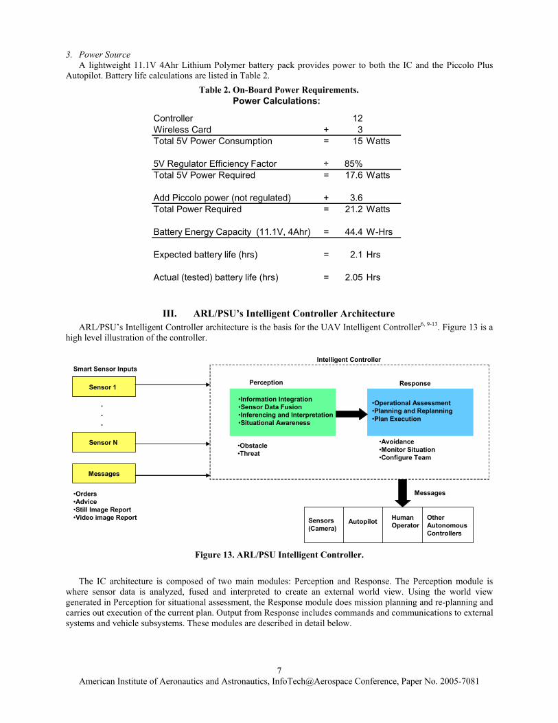
3. Power Source A lightweight 11.1V 4Ahr Lithium Polymer battery pack provides power to both the IC and the Piccolo Plus
Autopilot. Battery life calculations are listed in Table 2.
III. ARL/PSU’s Intelligent Controller Architecture ARL/PSU’s Intelligent Controller architecture is the basis for the UAV Intelligent Controller6, 9-13. Figure 13 is a
high level illustration of the controller.
Messages
Smart Sensor Inputs
Sensor 1
Sensor N
.
.
.
•Orders•Advice•Still Image Report•Video image Report
Perception
•Information Integration•Sensor Data Fusion•Inferencing and Interpretation•Situational Awareness
Response
•Operational Assessment•Planning and Replanning•Plan Execution
•Obstacle•Threat
•Avoidance•Monitor Situation•Configure Team
Intelligent Controller
Messages
Autopilot HumanOperator
OtherAutonomousControllers
Sensors(Camera)
Figure 13. ARL/PSU Intelligent Controller.
The IC architecture is composed of two main modules: Perception and Response. The Perception module is
where sensor data is analyzed, fused and interpreted to create an external world view. Using the world view generated in Perception for situational assessment, the Response module does mission planning and re-planning and carries out execution of the current plan. Output from Response includes commands and communications to external systems and vehicle subsystems. These modules are described in detail below.
Controller 12Wireless Card + 3Total 5V Power Consumption = 15 Watts
5V Regulator Efficiency Factor ÷ 85%Total 5V Power Required = 17.6 Watts
Add Piccolo power (not regulated) + 3.6Total Power Required = 21.2 Watts
Battery Energy Capacity (11.1V, 4Ahr) = 44.4 W-Hrs
Expected battery life (hrs) = 2.1 Hrs
Actual (tested) battery life (hrs) = 2.05 Hrs
Power Calculations:
Table 2. On-Board Power Requirements.
American Institute of Aeronautics and Astronautics, InfoTech@Aerospace Conference, Paper No. 2005-7081
8
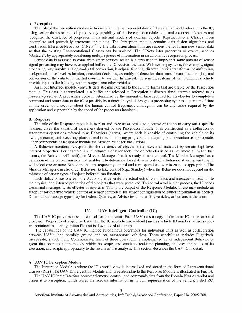
A. Perception The role of the Perception module is to create an internal representation of the external world relevant to the IC, using sensor data streams as inputs. A key capability of the Perception module is to make correct inferences and recognize the existence of properties in its internal models of external objects (Representational Classes) from incomplete and potentially erroneous input data. The Perception module contains data fusion algorithms and Continuous Inference Networks (CINets) 9-11. The data fusion algorithms are responsible for fusing new sensor data so that the existing Representational Classes can be updated. The CINets infer properties or events, such as “obstacle”, by appropriately combining multiple pieces of information in an automatic recognition process. Sensor data is assumed to come from smart sensors, which is a term used to imply that some amount of sensor signal processing may have been applied before the IC receives the data. With sensing systems, for example, signal processing may involve analog-to-digital conversion, bandpass filtering, discrete Fourier transforms, beamforming, background noise level estimation, detection decisions, assembly of detection data, cross-beam data merging, and conversion of the data to an inertial coordinate system. In general, the sensing systems of an autonomous vehicle provide input to the IC along with messages from other vehicles.
An Input Interface module converts data streams external to the IC into forms that are usable by the Perception module. This data is accumulated in a buffer and released to Perception at discrete time intervals referred to as processing cycles. A processing cycle is determined by the amount of time required for an effector to complete a command and return data to the IC or possibly by a timer. In typical designs, a processing cycle is a quantum of time on the order of a second, about the human control frequency, although it can be any value required by the application and supportable by the speed of the processors involved.
B. Response The role of the Response module is to plan and execute in real time a course of action to carry out a specific
mission, given the situational awareness derived by the Perception module. It is constructed as a collection of autonomous operations referred to as Behaviors (agents), where each is capable of controlling the vehicle on its own, generating and executing plans in real time, monitoring progress, and adapting plan execution as appropriate. Other components of Response include the Mission Manager and Actions.
A Behavior monitors Perception for the existence of objects in its interest as indicated by certain high-level inferred properties. For example, an Investigate Behavior looks for objects classified as “of interest”. When this occurs, the Behavior will notify the Mission Manager that it is ready to take control. The Mission Manager has a definition of the current mission that enables it to determine the relative priority of a Behavior at any given time. It will select one or more Behaviors that are requesting control and turn operations over to each, as appropriate. The Mission Manager can also order Behaviors to take control (e.g., Standby) when the Behavior does not depend on the existence of certain types of objects before it can function.
Each Behavior has one or more Actions that generate the actual output commands and messages in reaction to the physical and inferred properties of the objects that were perceived. To control a vehicle or process, the IC sends Command messages to its effector subsystems. This is the output of the Response Module. These may include an autopilot for dynamic vehicle control or sensor controllers for sensor configuration to gather information as needed. Other output message types may be Orders, Queries, or Advisories to other ICs, vehicles, or humans in the team.
IV. UAV Intelligent Controller (IC) The UAV IC provides mission control for the aircraft. Each UAV runs a copy of the same IC on its onboard
processor. Properties of a specific UAV that the IC needs to know about (such as vehicle ID number, sensors used) are contained in a configuration file that is downloaded at startup.
The capabilities of the UAV IC include autonomous operations for individual units as well as collaboration between UAVs (and possibly ground and sea autonomous vehicles). These capabilities include: FlightPath, Investigate, Standby, and Communicate. Each of these operations is implemented as an independent Behavior or agent that operates autonomously within its scope, and conducts real-time planning, analyzes the status of its execution, and adapts appropriately to the results of that analysis. This section describes the UAV IC in detail.
A. UAV IC Perception Module The Perception Module is where the IC’s world view is internalized and stored in the form of Representational
Classes (RCs). The UAV IC Perception Module and its relationship to the Response Module is illustrated in Fig. 14. The UAV IC Input Interface accepts telemetry, control, and commands data from the Piccolo Plus Autopilot and
passes it to Perception, which stores the relevant information in its own representation of the vehicle, a Self RC.
American Institute of Aeronautics and Astronautics, InfoTech@Aerospace Conference, Paper No. 2005-7081
9
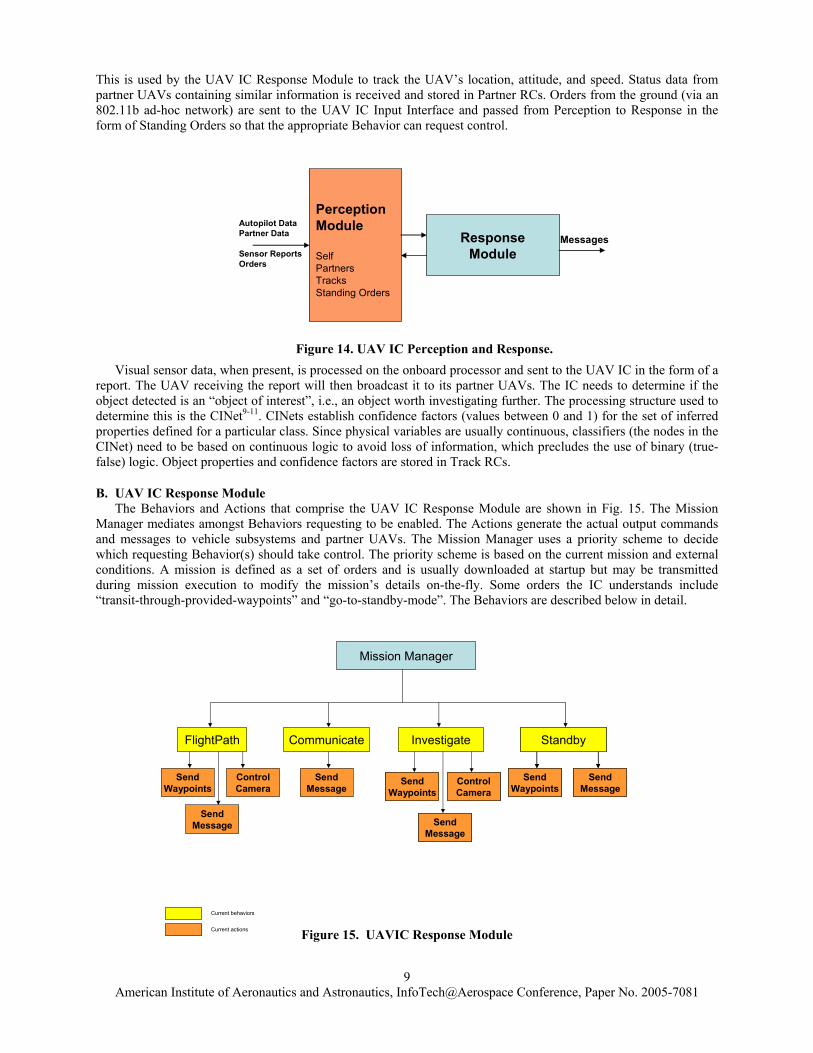
This is used by the UAV IC Response Module to track the UAV’s location, attitude, and speed. Status data from partner UAVs containing similar information is received and stored in Partner RCs. Orders from the ground (via an 802.11b ad-hoc network) are sent to the UAV IC Input Interface and passed from Perception to Response in the form of Standing Orders so that the appropriate Behavior can request control.
Visual sensor data, when present, is processed on the onboard processor and sent to the UAV IC in the form of a
report. The UAV receiving the report will then broadcast it to its partner UAVs. The IC needs to determine if the object detected is an “object of interest”, i.e., an object worth investigating further. The processing structure used to determine this is the CINet9-11. CINets establish confidence factors (values between 0 and 1) for the set of inferred properties defined for a particular class. Since physical variables are usually continuous, classifiers (the nodes in the CINet) need to be based on continuous logic to avoid loss of information, which precludes the use of binary (true-false) logic. Object properties and confidence factors are stored in Track RCs.
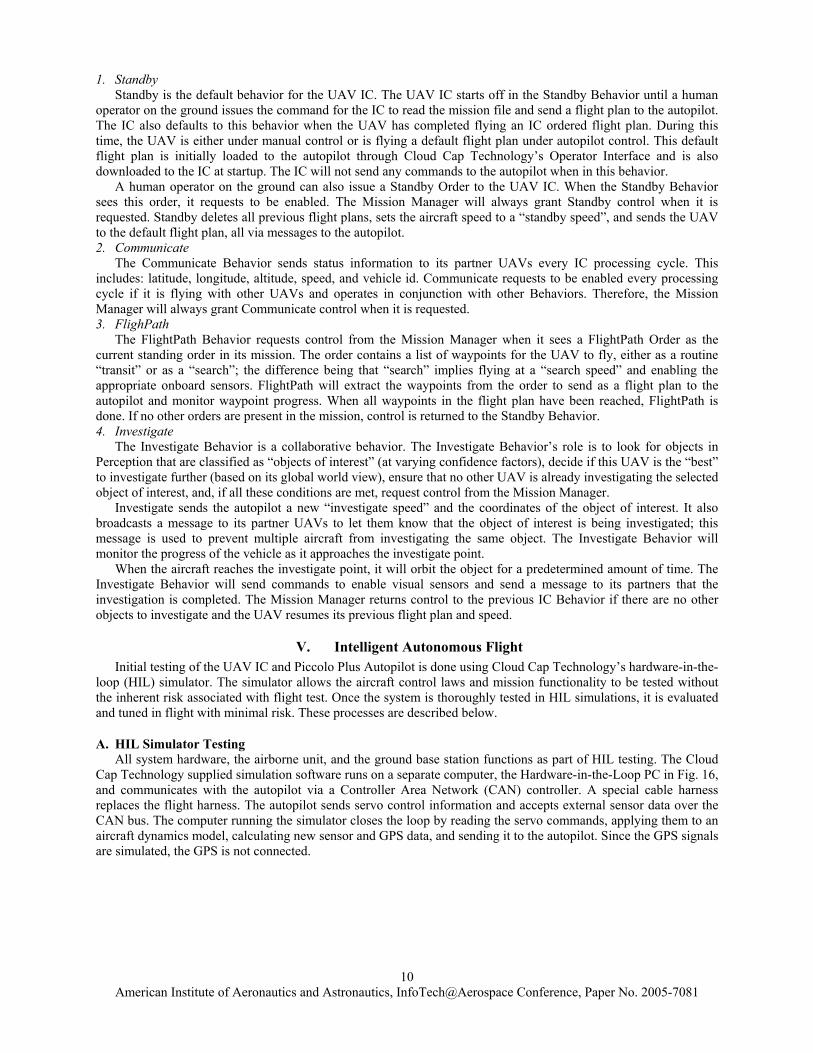
B. UAV IC Response Module The Behaviors and Actions that comprise the UAV IC Response Module are shown in Fig. 15. The Mission Manager mediates amongst Behaviors requesting to be enabled. The Actions generate the actual output commands and messages to vehicle subsystems and partner UAVs. The Mission Manager uses a priority scheme to decide which requesting Behavior(s) should take control. The priority scheme is based on the current mission and external conditions. A mission is defined as a set of orders and is usually downloaded at startup but may be transmitted during mission execution to modify the mission’s details on-the-fly. Some orders the IC understands include “transit-through-provided-waypoints” and “go-to-standby-mode”. The Behaviors are described below in detail.
Perception Module
SelfPartnersTracksStanding Orders
ResponseModule
MessagesAutopilot DataPartner Data
Sensor ReportsOrders
Figure 14. UAV IC Perception and Response.
Mission Manager
FlightPath
SendWaypoints
Communicate
SendMessage
Investigate
Current behaviors
Current actions
ControlCamera
SendMessage
SendWaypoints
ControlCamera
SendMessage
SendWaypoints
ControlCamera
SendMessage
Standby
SendMessage
SendWaypoints
Standby
SendMessage
SendWaypoints
Figure 15. UAVIC Response Module
American Institute of Aeronautics and Astronautics, InfoTech@Aerospace Conference, Paper No. 2005-7081
10
1. Standby Standby is the default behavior for the UAV IC. The UAV IC starts off in the Standby Behavior until a human
operator on the ground issues the command for the IC to read the mission file and send a flight plan to the autopilot. The IC also defaults to this behavior when the UAV has completed flying an IC ordered flight plan. During this time, the UAV is either under manual control or is flying a default flight plan under autopilot control. This default flight plan is initially loaded to the autopilot through Cloud Cap Technology’s Operator Interface and is also downloaded to the IC at startup. The IC will not send any commands to the autopilot when in this behavior.
A human operator on the ground can also issue a Standby Order to the UAV IC. When the Standby Behavior sees this order, it requests to be enabled. The Mission Manager will always grant Standby control when it is requested. Standby deletes all previous flight plans, sets the aircraft speed to a “standby speed”, and sends the UAV to the default flight plan, all via messages to the autopilot. 2. Communicate
The Communicate Behavior sends status information to its partner UAVs every IC processing cycle. This includes: latitude, longitude, altitude, speed, and vehicle id. Communicate requests to be enabled every processing cycle if it is flying with other UAVs and operates in conjunction with other Behaviors. Therefore, the Mission Manager will always grant Communicate control when it is requested. 3. FlighPath
The FlightPath Behavior requests control from the Mission Manager when it sees a FlightPath Order as the current standing order in its mission. The order contains a list of waypoints for the UAV to fly, either as a routine “transit” or as a “search”; the difference being that “search” implies flying at a “search speed” and enabling the appropriate onboard sensors. FlightPath will extract the waypoints from the order to send as a flight plan to the autopilot and monitor waypoint progress. When all waypoints in the flight plan have been reached, FlightPath is done. If no other orders are present in the mission, control is returned to the Standby Behavior. 4. Investigate
The Investigate Behavior is a collaborative behavior. The Investigate Behavior’s role is to look for objects in Perception that are classified as “objects of interest” (at varying confidence factors), decide if this UAV is the “best” to investigate further (based on its global world view), ensure that no other UAV is already investigating the selected object of interest, and, if all these conditions are met, request control from the Mission Manager.
Investigate sends the autopilot a new “investigate speed” and the coordinates of the object of interest. It also broadcasts a message to its partner UAVs to let them know that the object of interest is being investigated; this message is used to prevent multiple aircraft from investigating the same object. The Investigate Behavior will monitor the progress of the vehicle as it approaches the investigate point.
When the aircraft reaches the investigate point, it will orbit the object for a predetermined amount of time. The Investigate Behavior will send commands to enable visual sensors and send a message to its partners that the investigation is completed. The Mission Manager returns control to the previous IC Behavior if there are no other objects to investigate and the UAV resumes its previous flight plan and speed.
V. Intelligent Autonomous Flight Initial testing of the UAV IC and Piccolo Plus Autopilot is done using Cloud Cap Technology’s hardware-in-the-
loop (HIL) simulator. The simulator allows the aircraft control laws and mission functionality to be tested without the inherent risk associated with flight test. Once the system is thoroughly tested in HIL simulations, it is evaluated and tuned in flight with minimal risk. These processes are described below.
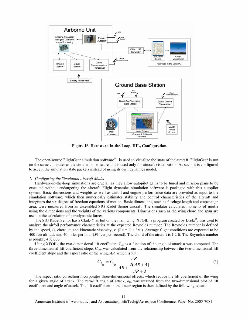
A. HIL Simulator Testing All system hardware, the airborne unit, and the ground base station functions as part of HIL testing. The Cloud
Cap Technology supplied simulation software runs on a separate computer, the Hardware-in-the-Loop PC in Fig. 16, and communicates with the autopilot via a Controller Area Network (CAN) controller. A special cable harness replaces the flight harness. The autopilot sends servo control information and accepts external sensor data over the CAN bus. The computer running the simulator closes the loop by reading the servo commands, applying them to an aircraft dynamics model, calculating new sensor and GPS data, and sending it to the autopilot. Since the GPS signals are simulated, the GPS is not connected.
American Institute of Aeronautics and Astronautics, InfoTech@Aerospace Conference, Paper No. 2005-7081
11
Figure 16. Hardware-In-the-Loop, HIL, Configuration.
The open-source FlightGear simulation software14 is used to visualize the state of the aircraft. FlightGear is run
on the same computer as the simulation software and is used only for aircraft visualization. As such, it is configured to accept the simulation state packets instead of using its own dynamics model. 1. Configuring the Simulation Aircraft Model Hardware-in-the-loop simulations are crucial, as they allow autopilot gains to be tuned and mission plans to be executed without endangering the aircraft. Flight dynamics simulation software is packaged with this autopilot system. Basic dimensions and weights as well as airfoil and engine performance data are provided as input to the simulation software, which then numerically estimates stability and control characteristics of the aircraft and integrates the six degree-of-freedom equations of motion. Basic dimensions, such as fuselage length and empennage area, were measured from an assembled SIG Kadet Senior aircraft. The simulator calculates moments of inertia using the dimensions and the weights of the various components. Dimensions such as the wing chord and span are used in the calculation of aerodynamic forces.
The SIG Kadet Senior has a Clark-Y airfoil on the main wing. XFOIL, a program created by Drela15, was used to analyze the airfoil performance characteristics at the expected Reynolds number. The Reynolds number is defined by the speed, U, chord, c, and kinematic viscosity, ν. (Re = U c / ν ). Average flight conditions are expected to be 400 feet altitude and 40 miles per hour (59 feet per second). The chord of the aircraft is 1.2 ft. The Reynolds number is roughly 450,000.
Using XFOIL, the two-dimensional lift coefficient Clα as a function of the angle of attack α was computed. The three-dimensional lift coefficient slope, CLα, was calculated from the relationship between the two-dimensional lift coefficient slope and the aspect ratio of the wing, AR, which is 5.5.
2)4(2
++
+=
ARARAR
ARCC lL αα (1)
The aspect ratio correction incorporates three-dimensional effects, which reduce the lift coefficient of the wing for a given angle of attack. The zero-lift angle of attack, α0, was retained from the two-dimensional plot of lift coefficient and angle of attack. The lift coefficient in the linear region is then defined by the following equation.
American Institute of Aeronautics and Astronautics, InfoTech@Aerospace Conference, Paper No. 2005-7081
12
)( 0ααα
−= LL CC (2)
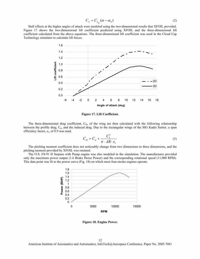
Stall effects at the higher angles of attack were modeled using the two-dimensional results that XFOIL provided. Figure 17 shows the two-dimensional lift coefficient predicted using XFOIL and the three-dimensional lift coefficient calculated from the above equations. The three-dimensional lift coefficient was used in the Cloud Cap Technology simulator to calculate lift forces.
0.0
0.2
0.4
0.6
0.8
1.0
1.2
1.4
1.6
-6 -4 -2 0 2 4 6 8 10 12 14 16 18
Angle of attack (deg)
Lift
coe
ffic
ient
2D
3D
Figure 17. Lift Coefficient.
The three-dimensional drag coefficient, CD, of the wing are then calculated with the following relationship
between the profile drag, Cd, and the induced drag. Due to the rectangular wings of the SIG Kadet Senior, a span efficiency factor, es, of 0.9 was used.
s
LdD eAR
CCC⋅⋅
+=π
2
(3)
The pitching moment coefficient does not noticeably change from two dimensions to three dimensions, and the pitching moment provided by XFOIL was retained. The O.S. FS-91 II Surpass with Pump engine was also modeled in the simulation. The manufacturer provided only the maximum power output (1.6 Brake Horse Power) and the corresponding rotational speed (11,000 RPM). This data point was fit to the power curve (Fig. 18) on which most four-stroke engines operate.
00.20.40.60.8
11.21.41.61.8
0 5000 10000 15000
RPM
Pow
er (B
HP)
Figure 18. Engine Power.
American Institute of Aeronautics and Astronautics, InfoTech@Aerospace Conference, Paper No. 2005-7081
13
2. Tuning Autopilot Gains The autopilot uses eight different feedback loops with proportional, integral, derivative (PID) compensation. The longitudinal and lateral/directional modes are decoupled. Not all of the available loops were used in this application. Table 3 lists the loops used and provides a description of each16.
Table 3. Summary Of Autopilot Feedback Loops.
Loop Inputs Outputs Comp. Notes Dynamic Pressure
Dynamic pressure
Elevator PID Maintains a commanded dynamic pressure.
Altitude Static pressure Throttle PID Maintains a commanded altitude. Tracker GPS Turn rate
command PD Drives the turn rate loop to achieve desired
track targets. Roll Roll angle Aileron PI Turn rate control and roll angle disturbance
rejection. Pitch Pitch angle Elevator PD Damps out pitch oscillations. Yaw Yaw rate Rudder P Damps out yaw oscillations
The autopilot gains are tuned one feedback loop at a time. The aircraft is trimmed and the turn rate control loop
is turned on. This loop uses roll angle feedback with proportional and integral compensation to control turn rate using the ailerons. The gains are adjusted from their default values until perturbations in bank angle are corrected and turn rate commands are followed without excess oscillation. Building upon the turn rate control loop, the airspeed, pitch damper, yaw damper, and altitude loops are sequentially tuned in a similar manner starting from their default values. Finally, the tracker, which is responsible for following a path defined by waypoints, is tuned after the rest of the autopilot loops are operational.
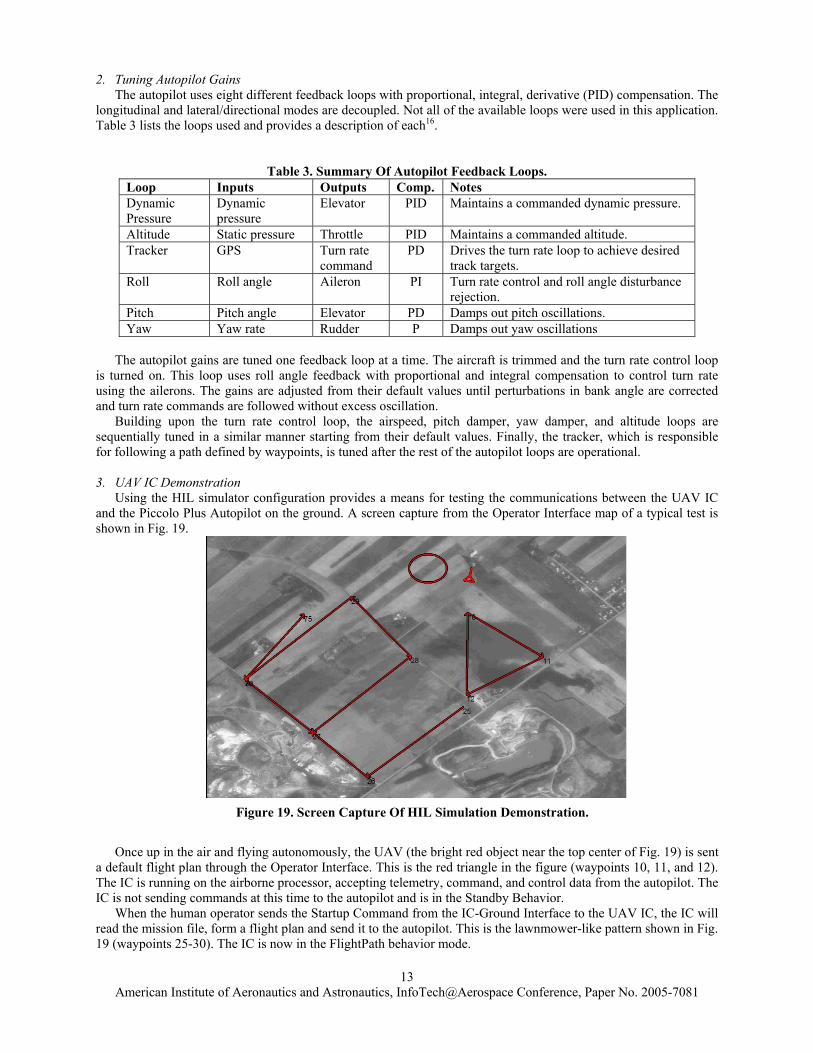
3. UAV IC Demonstration
Using the HIL simulator configuration provides a means for testing the communications between the UAV IC and the Piccolo Plus Autopilot on the ground. A screen capture from the Operator Interface map of a typical test is shown in Fig. 19.
Once up in the air and flying autonomously, the UAV (the bright red object near the top center of Fig. 19) is sent a default flight plan through the Operator Interface. This is the red triangle in the figure (waypoints 10, 11, and 12). The IC is running on the airborne processor, accepting telemetry, command, and control data from the autopilot. The IC is not sending commands at this time to the autopilot and is in the Standby Behavior.
When the human operator sends the Startup Command from the IC-Ground Interface to the UAV IC, the IC will read the mission file, form a flight plan and send it to the autopilot. This is the lawnmower-like pattern shown in Fig. 19 (waypoints 25-30). The IC is now in the FlightPath behavior mode.
Figure 19. Screen Capture Of HIL Simulation Demonstration.
American Institute of Aeronautics and Astronautics, InfoTech@Aerospace Conference, Paper No. 2005-7081
14
During its flight, the UAV IC receives a simulated camera report (from a human operator, as opposed to an actual report from a partner UAV). The IC Perception Module determines that the object is “of interest.” The Investigate Behavior of the IC requests, and is granted, control and instructs the autopilot to send the UAV to the location of the object and orbit. This is shown by the red circle in Fig. 19.
The UAV returns to the point where it deviates from its flight plan (waypoint 75) when it is done orbiting and continues to finish the plan (waypoint 30). When completed, the IC will go into the Standby Behavior and send the autopilot commands to delete the IC ordered flight plan (waypoints 25–30) and return to the default plan (waypoints 10–12).
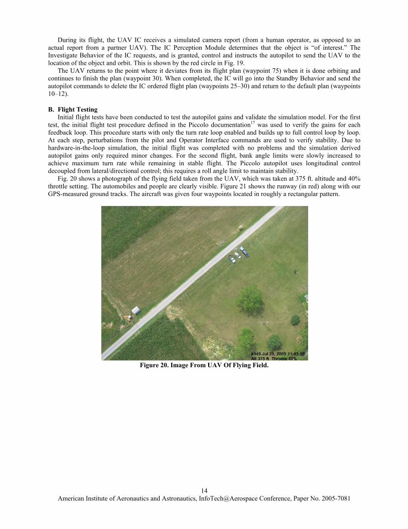
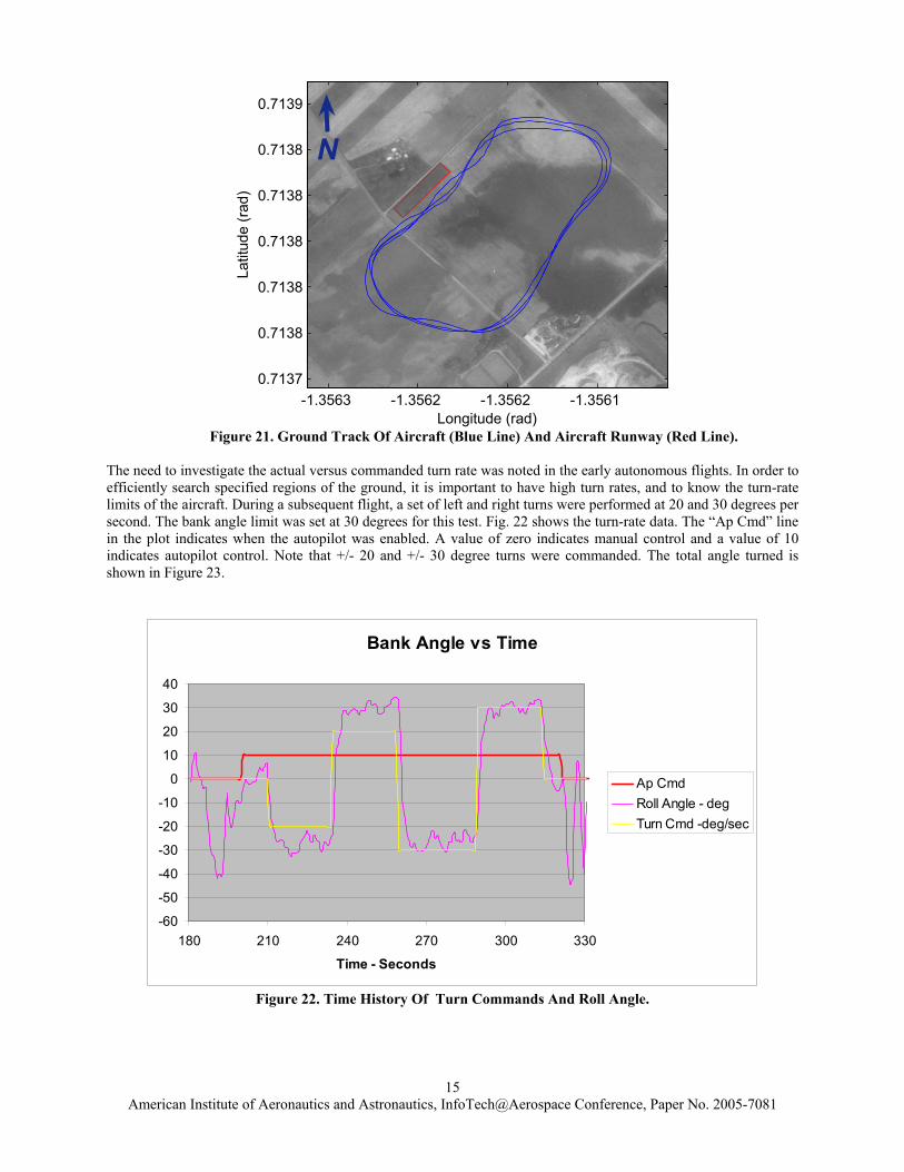
B. Flight Testing Initial flight tests have been conducted to test the autopilot gains and validate the simulation model. For the first test, the initial flight test procedure defined in the Piccolo documentation17 was used to verify the gains for each feedback loop. This procedure starts with only the turn rate loop enabled and builds up to full control loop by loop. At each step, perturbations from the pilot and Operator Interface commands are used to verify stability. Due to hardware-in-the-loop simulation, the initial flight was completed with no problems and the simulation derived autopilot gains only required minor changes. For the second flight, bank angle limits were slowly increased to achieve maximum turn rate while remaining in stable flight. The Piccolo autopilot uses longitudinal control decoupled from lateral/directional control; this requires a roll angle limit to maintain stability. Fig. 20 shows a photograph of the flying field taken from the UAV, which was taken at 375 ft. altitude and 40% throttle setting. The automobiles and people are clearly visible. Figure 21 shows the runway (in red) along with our GPS-measured ground tracks. The aircraft was given four waypoints located in roughly a rectangular pattern.
Figure 20. Image From UAV Of Flying Field.
American Institute of Aeronautics and Astronautics, InfoTech@Aerospace Conference, Paper No. 2005-7081
15
Longitude (rad)
Latitude (rad)
-1.3563 -1.3562 -1.3562 -1.35610.7137
0.7138
0.7138
0.7138
0.7138
0.7138
0.7139
N
Figure 21. Ground Track Of Aircraft (Blue Line) And Aircraft Runway (Red Line).
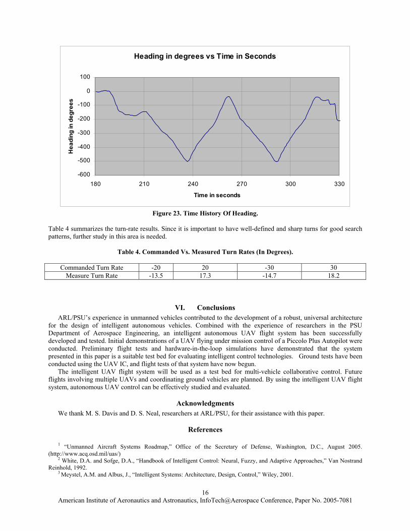
The need to investigate the actual versus commanded turn rate was noted in the early autonomous flights. In order to efficiently search specified regions of the ground, it is important to have high turn rates, and to know the turn-rate limits of the aircraft. During a subsequent flight, a set of left and right turns were performed at 20 and 30 degrees per second. The bank angle limit was set at 30 degrees for this test. Fig. 22 shows the turn-rate data. The “Ap Cmd” line in the plot indicates when the autopilot was enabled. A value of zero indicates manual control and a value of 10 indicates autopilot control. Note that +/- 20 and +/- 30 degree turns were commanded. The total angle turned is shown in Figure 23.
Bank Angle vs Time
-60
-50
-40
-30
-20
-10
0
10
20
30
40
180 210 240 270 300 330
Time - Seconds
Ap CmdRoll Angle - degTurn Cmd -deg/sec
Figure 22. Time History Of Turn Commands And Roll Angle.
American Institute of Aeronautics and Astronautics, InfoTech@Aerospace Conference, Paper No. 2005-7081
16
Heading in degrees vs Time in Seconds
-600
-500
-400
-300
-200
-100
0
100
180 210 240 270 300 330
Time in seconds
Hea
ding
in d
egre
es
Figure 23. Time History Of Heading.
Table 4 summarizes the turn-rate results. Since it is important to have well-defined and sharp turns for good search patterns, further study in this area is needed.
Table 4. Commanded Vs. Measured Turn Rates (In Degrees).
Commanded Turn Rate -20 20 -30 30 Measure Turn Rate -13.5 17.3 -14.7 18.2
VI. Conclusions ARL/PSU’s experience in unmanned vehicles contributed to the development of a robust, universal architecture
for the design of intelligent autonomous vehicles. Combined with the experience of researchers in the PSU Department of Aerospace Engineering, an intelligent autonomous UAV flight system has been successfully developed and tested. Initial demonstrations of a UAV flying under mission control of a Piccolo Plus Autopilot were conducted. Preliminary flight tests and hardware-in-the-loop simulations have demonstrated that the system presented in this paper is a suitable test bed for evaluating intelligent control technologies. Ground tests have been conducted using the UAV IC, and flight tests of that system have now begun.
The intelligent UAV flight system will be used as a test bed for multi-vehicle collaborative control. Future flights involving multiple UAVs and coordinating ground vehicles are planned. By using the intelligent UAV flight system, autonomous UAV control can be effectively studied and evaluated.
Acknowledgments We thank M. S. Davis and D. S. Neal, researchers at ARL/PSU, for their assistance with this paper.
References
1 “Unmanned Aircraft Systems Roadmap,” Office of the Secretary of Defense, Washington, D.C., August 2005. (http://www.acq.osd.mil/uas/)
2 White, D.A. and Sofge, D.A., “Handbook of Intelligent Control: Neural, Fuzzy, and Adaptive Approaches,” Van Nostrand Reinhold, 1992.
3 Meystel, A.M. and Albus, J., “Intelligent Systems: Architecture, Design, Control,” Wiley, 2001.
American Institute of Aeronautics and Astronautics, InfoTech@Aerospace Conference, Paper No. 2005-7081
17
4 Hopgood, A.A., “Intelligent Systems for Engineers and Scientists,” CRC Press, 2001. 5 Evans and E.R. Messina, “Performance Metrics for Intelligent Systems,” Proceedings of the 2000 PerMIS Workshop, pp.
101-104, Aug 14-16, 2000, Gaithersburg, MD. 6 Stover, J.A. and Kumar, Ratnesh, "A Behavior-based Architecture for the Design of Intelligent Controllers for Autonomous
Systems," IEEE International Symposium on Intelligent Control/Intelligent Systems and Semiotics, Cambridge, MA, pp. 308-313. Sept. 15-17, 1999.
7 Johnson, E.N., et al. “Development and Test of Highly Autonomous Unmanned Aerial Vehicles,” Journal of Aerospace Computing, Information, and Communication, Vol. 1, 2004, pp. 486-501.
8 Chalmers, R.W., et al. “Cooperating Unmanned Vehicles,” AIAA 1st Intelligent Systems Technical Conference, pp. 1-8. September 20-22, 2004.
9 Stover, J.A., et al. "Continuous Inference Networks for Autonomous Systems," IEEE Conference on Neural Networks for Ocean Engineering, pp. 177-183. Aug. 17, 1991.
10Stover, J.A. and Gibson, R.E., "Modeling Confusion for Autonomous Systems," SPIE, Science Artificial Neural Networks, 1710, pp. 547-555, 1992.
11 Stover, J.A., Hall, D.L., and Gibson, R.E., “A Fuzzy-Logic Architecture for Autonomous Multisensor Data Fusion," IEEE Transactions on Industrial Electronics, 43, pp. 403-410, 1996.
12 Stover, J A., and Gibson, R.E., The Applied Research Laboratory/The Pennsylvania State University, State College, PA, “Controller for Autonomous Device,” US Patent #5,642,467, Issued June 1997.
13 Weiss, L., "Intelligent Collaborative Control for UAVs," AIAA Paper No. 2005-6900, AIAA InfoTech@Aerospace Conference, Washington D.C., Sept. 26-29, 2005.
14 http://ww.flightgear.org/ 15 http://raphael.mit.edu/xfoil/ 16 Vaglienti, B., Hoag, R., and Niculescu, M., “Piccolo System User Guide,” Cloud Cap Technology [online], URL:
http://www.cloudcaptech.com/ [cited 7 September 2004]. 17 Vaglienti, B., Hoag, R., and Miller, T., “Piccolo Aircraft Integration Guidelines,” Cloud Cap Technology [online], URL:
http://www.cloudcaptech.com/ [cited 7 September 2004].