intelligent transport systems (its); cooperative its (c-its); release 1 framework for public...
DESCRIPTION
Intelligent Transport Systems (ITS);Cooperative ITS (C-ITS);Release 1Framework for Public Mobile Networks in Cooperative ITS (C-ITS)TRANSCRIPT
ETSI TR 102 962 V1.1.1 (2012-02)
Intelligent Transport Systems (ITS); Framework for Public Mobile Networks in
Cooperative ITS (C-ITS)
Technical Report
ETSI
ETSI TR 102 962 V1.1.1 (2012-02) 2
Reference DTR/ITS-0020035
Keywords 3GPP, architecture, IPv6, ITS
ETSI
650 Route des Lucioles F-06921 Sophia Antipolis Cedex - FRANCE
Tel.: +33 4 92 94 42 00 Fax: +33 4 93 65 47 16
Siret N° 348 623 562 00017 - NAF 742 C
Association à but non lucratif enregistrée à la Sous-Préfecture de Grasse (06) N° 7803/88
Important notice
Individual copies of the present document can be downloaded from: http://www.etsi.org
The present document may be made available in more than one electronic version or in print. In any case of existing or perceived difference in contents between such versions, the reference version is the Portable Document Format (PDF).
In case of dispute, the reference shall be the printing on ETSI printers of the PDF version kept on a specific network drive within ETSI Secretariat.
Users of the present document should be aware that the document may be subject to revision or change of status. Information on the current status of this and other ETSI documents is available at
http://portal.etsi.org/tb/status/status.asp
If you find errors in the present document, please send your comment to one of the following services: http://portal.etsi.org/chaircor/ETSI_support.asp
Copyright Notification
No part may be reproduced except as authorized by written permission. The copyright and the foregoing restriction extend to reproduction in all media.
© European Telecommunications Standards Institute 2012.
All rights reserved.
DECTTM, PLUGTESTSTM, UMTSTM and the ETSI logo are Trade Marks of ETSI registered for the benefit of its Members. 3GPPTM and LTE™ are Trade Marks of ETSI registered for the benefit of its Members and
of the 3GPP Organizational Partners. GSM® and the GSM logo are Trade Marks registered and owned by the GSM Association.
ETSI
ETSI TR 102 962 V1.1.1 (2012-02) 3
Contents
Intellectual Property Rights ................................................................................................................................ 5
Foreword ............................................................................................................................................................. 5
Introduction ........................................................................................................................................................ 5
1 Scope ........................................................................................................................................................ 6
2 References ................................................................................................................................................ 6
2.1 Normative references ......................................................................................................................................... 6
2.2 Informative references ........................................................................................................................................ 6
3 Definitions and abbreviations ................................................................................................................... 9
3.1 Definitions .......................................................................................................................................................... 9
3.2 Abbreviations ..................................................................................................................................................... 9
4 Overview ................................................................................................................................................ 10
5 Communication characteristics and features of cellular networks within C-ITS context ...................... 10
5.1 Introduction ...................................................................................................................................................... 11
5.1.1 Unicast Scenario ......................................................................................................................................... 11
5.1.2 MBMS Scenario (Broadcast Scenario) ....................................................................................................... 11
5.2 UMTS (HSPA) ................................................................................................................................................. 12
Technology Overview ....................................................................................................................................................... 12
5.2.2 HSPA unicast uplink delay ......................................................................................................................... 14
5.2.3 HSPA Unicast downlink delay ................................................................................................................... 14
5.2.4 Downlink distribution over HSPA ETWS .................................................................................................. 14
5.2.5 CoCar trials and results ............................................................................................................................... 15
5.2.5.1 System overview ................................................................................................................................... 15
5.2.5.2 Unicast Mode ........................................................................................................................................ 15
5.2.5.3 Broadcast Mode .................................................................................................................................... 19
5.2.5.4 Final conclusions ................................................................................................................................... 21
5.3 GSM / EDGE ................................................................................................................................................... 22
5.3.1 Using GSM / GPRS uplink delay ............................................................................................................... 22
5.3.2 Downlink distribution over GSM / GPRS ETWS ....................................................................................... 22
5.3.3 Downlink distribution over GSM / GPRS in unicast .................................................................................. 23
5.4 LTE .................................................................................................................................................................. 23
5.4.1 Technology overview ................................................................................................................................. 23
5.4.2 Physical downlink control channel ............................................................................................................. 24
5.4.3 Physical uplink control channel .................................................................................................................. 24
5.4.4 CoCarX Results .......................................................................................................................................... 24
5.4.4.1 System Overview .................................................................................................................................. 25
5.4.4.2 CAM Scenario ....................................................................................................................................... 25
5.4.4.3 DENM Messages .................................................................................................................................. 30
6 Service Enablers in support of C-ITS services ....................................................................................... 34
6.1 System Architecture ......................................................................................................................................... 34
6.1.1 C-ITS Application Server (C-ITS AS)........................................................................................................ 37
6.1.2 Geomessaging Enabler ............................................................................................................................... 37
6.1.3 Core Network Infrastructure Nodes ............................................................................................................ 38
6.1.3.1 Benefits of IMS ..................................................................................................................................... 38
6.1.3.1.1 Support for Quality of Service (QoS) .............................................................................................. 38
6.1.3.1.2 Differentiated Charging ................................................................................................................... 38
6.1.3.1.3 Support for Roaming ....................................................................................................................... 39
6.1.4 Warning Areas ............................................................................................................................................ 39
6.1.5 Geocast Client ............................................................................................................................................. 40
6.1.6 C-ITS applications ...................................................................................................................................... 40
6.2 Call flows ......................................................................................................................................................... 40
6.2.1 Registration and session initiation .............................................................................................................. 41
6.2.2 C-ITS Application initiation ....................................................................................................................... 42
ETSI
ETSI TR 102 962 V1.1.1 (2012-02) 4
6.2.2.1 Subsequent uplink data exchange ......................................................................................................... 43
6.2.3 Message dissemination (downlink) ............................................................................................................. 44
6.2.4 Vehicle location update .............................................................................................................................. 44
6.3 Mapping the Geomessaging Enabler to C-ITS architecture ............................................................................. 45
6.3.1 Scalability and handling of multiple Geomessaging Enablers .................................................................... 46
6.3.2 Handling of multiple cellular networks ...................................................................................................... 47
7 Identification and enhancements of ITS applications and related use cases .......................................... 47
7.1 Introduction ...................................................................................................................................................... 47
7.2 Use case support ............................................................................................................................................... 48
7.2.1 Introduction................................................................................................................................................. 48
7.2.2 DENM ........................................................................................................................................................ 48
7.2.3 CAM ........................................................................................................................................................... 48
7.3 BSA Classification ........................................................................................................................................... 49
7.3.1 Active road safety and Cooperative traffic efficiency use cases ................................................................. 49
7.3.2 Co-operative local services and Global internet services use cases ............................................................ 51
8 Impact on standards for cooperative ITS................................................................................................ 52
8.1 Introduction to standardization for C-ITS ........................................................................................................ 52
8.2 C-ITS architectures........................................................................................................................................... 52
8.2.1 C-ITS overall architecture .......................................................................................................................... 52
8.2.2 C-ITS communications architecture ........................................................................................................... 53
8.3 C-ITS communications ..................................................................................................................................... 53
8.3.1 Recognition of LTE in an ITS station ......................................................................................................... 53
8.3.2 ITS station management ............................................................................................................................. 54
8.3.3 Communication profile selection ................................................................................................................ 54
8.4 C-ITS applications ............................................................................................................................................ 54
Annex A: Standard development summary ......................................................................................... 55
Annex B: eMBMS for the delivery of vehicular services .................................................................... 57
B.1 eMBMS characteristics .......................................................................................................................... 57
B.2 Coverage areas associated with eMBMS ............................................................................................... 58
B.3 eMBMS channels ................................................................................................................................... 58
B.4 eMBMS performance in LTE ................................................................................................................. 59
B.5 Evaluation of eMBMS for the delivery of ITS services ......................................................................... 61
Annex C: Bibliography .......................................................................................................................... 62
History .............................................................................................................................................................. 63
ETSI
ETSI TR 102 962 V1.1.1 (2012-02) 5
Intellectual Property Rights IPRs essential or potentially essential to the present document may have been declared to ETSI. The information pertaining to these essential IPRs, if any, is publicly available for ETSI members and non-members, and can be found in ETSI SR 000 314: "Intellectual Property Rights (IPRs); Essential, or potentially Essential, IPRs notified to ETSI in respect of ETSI standards", which is available from the ETSI Secretariat. Latest updates are available on the ETSI Web server (http://ipr.etsi.org).
Pursuant to the ETSI IPR Policy, no investigation, including IPR searches, has been carried out by ETSI. No guarantee can be given as to the existence of other IPRs not referenced in ETSI SR 000 314 (or the updates on the ETSI Web server) which are, or may be, or may become, essential to the present document.
Foreword This Technical Report (TR) has been produced by ETSI Technical Committee Intelligent Transport System (ITS).
Introduction Cooperative Intelligent Transport Systems (C-ITS) applications cover a wide range of different scenarios for road transport with entities in the infrastructure (already existent or newly to be developed), in vehicles, and in portable devices. The related functional communication needs demand a multiplicity of communication technologies out of the classes:
• Ad-hoc communications, e.g. ITS-G5 standardized at ETSI (equivalent to CALM M5 standardized at ISO), Infra-Red (IR) standardized at ISO, and others such as millimetric waves.
• Cellular network communications, e.g. UMTS, LTE and further generations.
ETSI
ETSI TR 102 962 V1.1.1 (2012-02) 6
1 Scope The present document is based on an analysis of cooperative ITS (C-ITS) services using public mobile cellular networks for communications between ITS stations in order to:
• identify related functional requirements on the ITS architecture,
• identify required amendments / modifications of existing standards on C-ITS in order to enable usage of public mobile cellular networks,
• identify functionality to be specified in new ITS standards to be developed under M/453.
The result of the investigations is illustrated in the present document.
2 References References are either specific (identified by date of publication and/or edition number or version number) or non-specific. For specific references, only the cited version applies. For non-specific references, the latest version of the reference document (including any amendments) applies.
Referenced documents which are not found to be publicly available in the expected location might be found at http://docbox.etsi.org/Reference.
NOTE: While any hyperlinks included in this clause were valid at the time of publication, ETSI cannot guarantee their long term validity.
2.1 Normative references The following referenced documents are necessary for the application of the present document.
Not applicable.
2.2 Informative references The following referenced documents are not necessary for the application of the present document but they assist the user with regard to a particular subject area.
Non-standard references.
[i.1] M/453 EN 2009: "Standardisation mandate addressed to cen, cenelec and etsi in the field of information and communication technologies to support the interoperability of co-operative systems for intelligent transport in the european community".
[i.2] Joint CEN and ETSI Response to Mandate M/453.
[i.3] EC/DGINFSO-USDOT/RITA 2009: "EU-U.S. Joint Declaration of Intent on Research Cooperation in Cooperative Systems".
[i.4] US DoT Research and Innovative Technology Administration, DTFH61-10-F-00045: "Core System Concept of Operations (ConOps)", 19.4.2011.
[i.5] An Optimized Grid-Based Geocasting Method for Cellular Mobile Networks.
NOTE: Available at: http://docbox.etsi.org/ITS/ITSWG2/05-CONTRIBUTIONS/2011/ITSWG2(11)0041_An_Optimized_Grid-Based_Geocasting_Method_for_Cellular_Mobile_Net.pdf
[i.6] Category A Liaison Agreement, ETSI, ISO, 20.5.2008.
ETSI
ETSI TR 102 962 V1.1.1 (2012-02) 7
[i.7] EC DG INFSO: "Global Harmonisation of ITS cooperative systems standards", Letter infoso.g.4(2011)1136082 to ETSI, 10.10.2011.
ETSI standard references
[i.8] ETSI TS 101 539-1: "Intelligent Transport Systems (ITS); V2V Application; Co-operative Awareness application specification".
[i.9] ETSI TS 101 539-2: "Intelligent Transport System (ITS); V2V Application; Intersection Collision Risk Warning Specification".
[i.10] ETSI TS 101 539-3: "Intelligent Transport Systems (ITS); V2V Application; Longitudinal Collision Risk Warning Specification.".
[i.11] ETSI TS 101 556-1: "Intelligent Transport Systems (ITS); I2V Application; Electric Vehicle Charging Spot Notification Specification".
[i.12] ETSI TS 102 636 (all parts): "Intelligent Transport Systems (ITS); Vehicular Communications; GeoNetworking".
[i.13] ETSI TS 102 637-1: "Intelligent Transport Systems (ITS); Vehicular Communications; Basic Set of Applications; Part 1: Functional Requirements".
[i.14] ETSI EN 302 637-2: "Intelligent Transport Systems (ITS); Vehicular Communications; Basic Set of Applications; Part 2: Specification of Cooperative Awareness Basic Service".
[i.15] ETSI EN 302 637-3: "Intelligent Transport Systems (ITS); Vehicular Communications; Basic Set of Applications; Part 3: Specifications of Decentralized Environmental Notification Basic Service".
[i.16] ETSI TR 102 638: "Intelligent Transport Systems (ITS); Vehicular Communications; Basic Set of Applications; Definitions".
[i.17] ETSI ES 202 663: "Intelligent Transport Systems (ITS); European profile standard for the physical and medium access control layer of Intelligent Transport Systems operating in the 5 GHz frequency band".
[i.18] ETSI EN 302 665: "Intelligent Transport Systems (ITS); Communications Architecture".
[i.19] ETSI TS 102 860: "Intelligent Transport Systems (ITS); Classification and management of ITS application objects".
[i.20] ETSI TS 102 890-1: "Intelligent Transport Systems (ITS); Facilities layer function; Communication Management specification".
[i.21] ETSI TS 102 890-2: "Intelligent Transport Systems (ITS); Facilities layer function; Services announcement specification".
[i.22] ETSI TS 102 894-1: "Intelligent Transport System (ITS); Users and Applications requirements; Facility layer structure, functional requirements and specifications;".
[i.23] ETSI DTS/ITS-0010021: "Intelligent Transport Systems; Facilities layer; Communication congestion control".
[i.24] ETSI EN 302 895: "Intelligent Transport Systems (ITS); Vehicular Communications; Basic Set of Applications; Local Dynamic Map (LDM) Specification".
IETF standard references
[i.25] IETF RFC 4145: "TCP-Based Media Transport in the Session Description Protocol (SDP)".
CEN/ISO standard references
[i.26] ISO 16444: "Intelligent transport systems - Communications access for land mobiles (CALM)-Geo-Routing".
ETSI
ETSI TR 102 962 V1.1.1 (2012-02) 8
[i.27] ISO 16445: "Intelligent transport systems - Communications access for land mobiles (CALM)-Handover architecture".
[i.28] ISO 17419: "Classification and management of ITS applications in a global context".
[i.29] ISO 17423: "ITS application requirements for selection of communication profiles".
[i.30] ISO/NP 17427: "European co-operative ITS framework architecture and roles and responsibilities in the context of co-operative ITS based on architecture(s) for cooperative systems".
[i.31] ISO 17515: "Intelligent transport systems -- Communications access for land mobiles (CALM)-LTE cellular systems".
[i.32] ISO 21212, "Intelligent Transport Systems - Communications access for land mobiles (CALM)-2G cellular systems".
[i.33] ISO 21213: "Intelligent Transport Systems - Communications access for land mobiles (CALM)-3G cellular systems".
[i.34] ISO 21214: "Intelligent Transport Systems - Communications access for land mobiles (CALM)-Infra-red systems".
[i.35] ISO 21215: "Intelligent transport systems - Communications access for land mobiles (CALM)-M5".
[i.36] ISO 21217: "Intelligent Transport Systems - Communications access for land mobiles (CALM)-Architecture".
[i.37] ISO 21218: "Intelligent Transport Systems - Communications access for land mobiles (CALM)-Medium service access points".
[i.38] ISO 24102-1: "Intelligent Transport Systems - Communications access for land mobiles (CALM)-ITS station management Part 1: Local management".
[i.39] ISO 24102-2: "Intelligent Transport Systems - Communications access for land mobiles (CALM)-ITS station management Part 2: Remote management".
[i.40] ISO 24102-3: "Intelligent Transport Systems - Communications access for land mobiles (CALM)-ITS station management Part 3: Service access points".
[i.41] ISO 24102-4: "Intelligent Transport Systems - Communications access for land mobiles (CALM)-ITS station management Part 4: Station-internal management communications".
[i.42] ISO 24102-5: "Intelligent transport systems - Communications access for land mobiles (CALM)-ITS station management Part 5: Fast service advertisement protocol (FSAP)".
[i.43] ISO 29281-2: "Intelligent transport systems - Communications access for land mobiles (CALM)-Non-IP networking Part 2: Fast networking & transport layer protocol (FNTP)".
IEEE standard references
[i.44] IEEE 1609: "Standard for Wireless Access in Vehicular Environments - WAVE" multipart deliverable.
Other technical references
[i.45] Motorola, EMBMS Performance Evaluation; 3GPP Tdoc R1-071975; April 23-24, 2007.
[i.46] ETSI TS 136 300: "LTE; Evolved Universal Terrestrial Radio Access (E-UTRA) and Evolved Universal Terrestrial Radio Access Network (E-UTRAN); Overall description; Stage 2".
[i.47] Dorbes, G. and Amosse, H. (2008): "Combining web 2.0 and ims: The road to new services and business models".
NOTE: Available at: http://www.alcatel-lucent.com/enrich/v2i12008/article_c3a2.html
ETSI
ETSI TR 102 962 V1.1.1 (2012-02) 9
[i.48] CoCar Consortium, AKTIV-CoCar: "Adaptive and Cooperative Technologies for Intelligent Traffic - Cooperative Cars", CoCar Feasibility Study Technology, Business and Dissemination.
[i.49] CoCar Consortium: "CoCarX Coperative Cars eXtended ITS services and communication architecture Deliverable D3".
[i.50] IEEE 802.11: ." Wireless Access in Vehicular Environments (WAVE): IEEE 1609 Standards Series".
[i.51] ETSI TS 136 211: "LTE; Evolved Universal Terrestrial Radio Access (E-UTRA); Physical channels and modulation".
3 Definitions and abbreviations
3.1 Definitions For the purposes of the present document, the terms and definitions given in [i.18], [i.36], [i.16] and the following apply:
geomessaging: application in charge of distribution of ITS messages into a geographical area
3.2 Abbreviations For the purposes of the present document, the abbreviations given in [i.18], [i.36], [i.16] and the following apply:
Abis Air interface APDU Application Protocol Data Unit BSA Basic Set of Applications BSC Base Station Controller BM-SC Broadcast Multicast Service Centre BTS Base Transceiver Station CHW Cellular Hazard Warning CELL_DCH Cell Dedicated Channel CELL_FACH Cell Forward Access Channel DL Downlink DRX Discontinuous Reception DPCH Dedicated physical channel ETWS Earthquake and Tsunami Warning System E2E End to End FACH Forward Access Channel FTAP Fast traffic access protocol GC-SAP Geocast Client Service Access Point HTTP Hyper Text Transfer Protocol IMS Internet Multimedia Subsystem Gb/Gn Interface between GGSN Node and Internet GSM Global System for Mobile Communications HSPA High Speed Packet Access HS-DSCH High speed dedicated shared channel LTE Long Term Evolution MBMS Multimedia Broadcast and Multicast Services MCS Modulation and Coding Scheme MTCH MBMS Traffic Channel MSCH MBMS Scheduling MCCH MBMS Control Channel MICH MBMS Notification Indicator Channel. MIMO Multiple-input and multiple-output MSA MBMS Service Area MS Mobile Station PDCH Physical Data Channel
ETSI
ETSI TR 102 962 V1.1.1 (2012-02) 10
RNC Radio Network Controller RLC Radio Link Controller RRC Radio Resource Control RTT Round Trip Time RTI Road Traffic Information RHW Road Hazard Warning SMSCB Short Message Service Cell Broadcast S-CCPCH Secondary Common Control Physical Channel SIP Session Initialization Protocol TTI Transmission Time Interval UE User Equipment UL Uplink UMTS Universal Mobile T URA_PCH Utran Registration Area-Paging Channel UDP User Datagram Protocol UA User Agent W-CDMA Wideband Code Division Multiple Access
4 Overview Starting from the architecture described in the published standards on ITS communication architecture [i.18] and [i.36], and considering primarily, but not exclusively, the basic set of applications identified in [i.16], a critical assessment of the applicability of the 3G and 4G mobile network access to support the described application scenarios is given in the present document. This analysis refers to technical standards developed by 3GPP. This analysis is based on the ITS station architecture. Additional technical background provided by R&D projects such as:
• CoCAR (http://www.aktiv-online.org/english/aktiv-cocar.html) [i.48],
• CoCARx (the follow-on project including integration between LTE [i.31] and WAVE-DSRC [i.44] access technologies) [i.49], and
• CVIS (http://www.cvisproject.org/),
is considered for the development of the present document.
Related standards from other SDOs working on C-ITS, e.g. CEN TC278 WG16 / ISO TC204 WG1, WG16, WG18, also are considered as appropriate.
This approach is coherent with the spirit of the "Joint CEN and ETSI Response to Mandate M/453" [i.2], with specific reference to clause 3.3 "Standardisation for Co-operative systems covering other media", and clause 4.2.3. "National R&D projects including national FOTs".
As result, the present document illustrates usage of cellular network technology for C-ITS.
Clause 5 presents communication characteristics and features of cellular networks.
Clause 6 identifies ITS applications and related use cases applicable over cellular networks communications, and their possible enhancements.
Clause 7 explains special features of cellular networks in support of C-ITS services.
Clause 8 illustrates the impact of cellular networks in C-ITS on the ITS communication architecture, and the required ITS station management, and further procedures.
5 Communication characteristics and features of cellular networks within C-ITS context
This clause describes the communication characteristics of cellular networks as considered to be applicable for C-ITS.
ETSI
ETSI TR 102 962 V1.1.1 (2012-02) 11
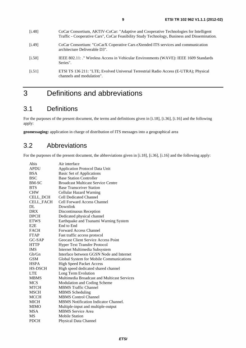
5.1 Introduction Cellular networks offer two modes of data transportation that can be used for V2V or V2I communications. Both modes require a backend network server that intercepts traffic from vehicles or traffic infrastructure and redistributes traffic to vehicles and traffic infrastructure after processing. To allow the backend server to redistribute traffic to the concerned vehicles, moving vehicles need to send location information to the backend server with a reasonable update rate. The following is a brief overview of these modes in more details.
5.1.1 Unicast Scenario
The unicast scenario is used both for uplink and downlink distribution. In the uplink case, vehicles send the message to the network. For downlink distribution, vehicles are addressed individually. In this case, the backend server (Traffic Information Server) sends the same message individually to all concerned vehicles and infrastructure nodes. This is illustrated in the exemplary Figure 5.1, and where upon "Transmit Trigger Events" (TTE) the moving road works vehicle sends its identification, type, speed, heading, and position via the cellular network to a traffic information server. This information is then distributed to all service users in the vicinity.
In order to identify users (approaching vehicles) that move towards the moving road works vehicle, the server also needs context information about every single user. One approach to realize such a user context is that all equipped cars regularly send their status, containing identification, location, heading, speed, etc. to the server. Another approach is for cars to make use of network-based positioning servers to obtain location information. This enables the server to track the vehicles and to identify those vehicles approaching the moving road works vehicle for which the Moving Road Works Warning is relevant. Accordingly, the service addresses single approaching vehicles by unicast communications and informs them about hazards or obstacles ahead.
Note that unicast scenario is always used for uplink regardless of the mode used in downlink distribution.
Figure 5.1: Unicast scenario example "Moving Road Works Warning"
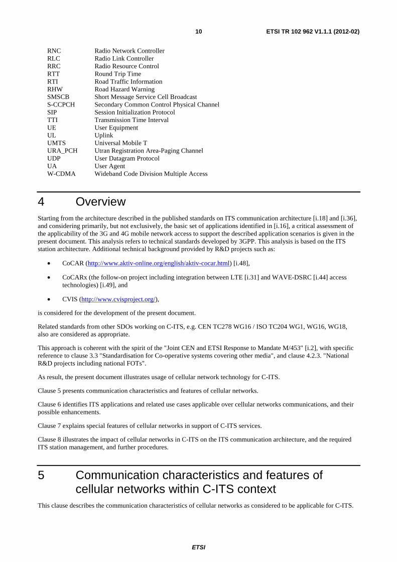
5.1.2 MBMS Scenario (Broadcast Scenario)
This scenario is used exclusively for downlink distribution of messages, and where all vehicles belonging to a broadcast area are addressed collectively, rather than individually. In the exemplary broadcast scenario depicted in Figure 5.2, the authorized server (Traffic Information Server) addresses the "Broadcast Multicast Service Centre" (BM-SC) to distribute the data via "Multimedia Broadcast and Multicast Services" MBMS. MBMS can maintain different broadcast areas, one of which in this exemplary case would be the highway area with the road works. One broadcast area can consist of any set of cells specified by the cellular operator.
ETSI
ETSI TR 102 962 V1.1.1 (2012-02) 12
Figure 5.2: MBMS scenario
One main difference to the unicast scenario is that no single user but the whole broadcast area is addressed. This means that it is not necessary to keep a complete user profile in the server that includes the rough position of the user. Thus, scalability and privacy are less critical in the MBMS scenario.
Furthermore, core network resources are saved, because every message is only transmitted once reaching all vehicles in the cell using the broadcast channel. If several vehicles are located in one cell, the broadcast solution is also more resource efficient on the radio interface.
This scenario also means that the received information is not that much personalized according to one certain user context. Here, the vehicle has to filter out relevant information itself. The larger the broadcast area the more processing has to be done in the vehicle.
Another variation of broadcast specified by 3GPP for 2G and 3G systems is the broadcast on the "Earthquake and Tsunami Warning System" (ETWS).
5.2 UMTS (HSPA) This clause presents a brief overview of the UMTS (HSPA) technology, its key characteristics and suitability for C-ITS. In addition, the results and conclusions from the CoCar project which used this technology are presented.
Technology Overview
UMTS was first standardized by 3rd Generation Partnership Project (3GPP) in 1999. UMTS is based on Direct Sequence Code Division Multiple Access (DS-CDMA), which means that every signal of a physical channel is spread over the whole carrier bandwidth by multiplying it with a certain channelization code, the Orthogonal Variable Spreading Factor (OVSF, short: SF) code. Thus, with the W-CDMA technology, a unique code identifies each physical channel, and the SF of the code determines the bit rate.
UMTS has undergone several enhancements over the years that can be briefly summarized as follows:
HSDPA The first enhancement to UMTS was introduced with High Speed Downlink Packet Access (HSDPA) in 3GPP Release 5. HPDPA increases the downlink data rates up to 14,4 Mbit/s. Work on this standard enhancement started in 2003 and the technology was finally commercially available in late 2005.
HSUPA High Speed Uplink Packet Access (HSUPA) was introduced to UMTS Release 6, improved uplink data rates up to 5,7 Mbit/s are possible. It can be seen as the counterpart to HSDPA. First networks have been rolled out using this Release 6 technology in 2007. HSUPA actually implements the same sort of techniques already used by HSDPA.
HSPA High Speed Packet Access (HSPA) is referred to as the combination of HSDPA and HSUPA.
ETSI
ETSI TR 102 962 V1.1.1 (2012-02) 13
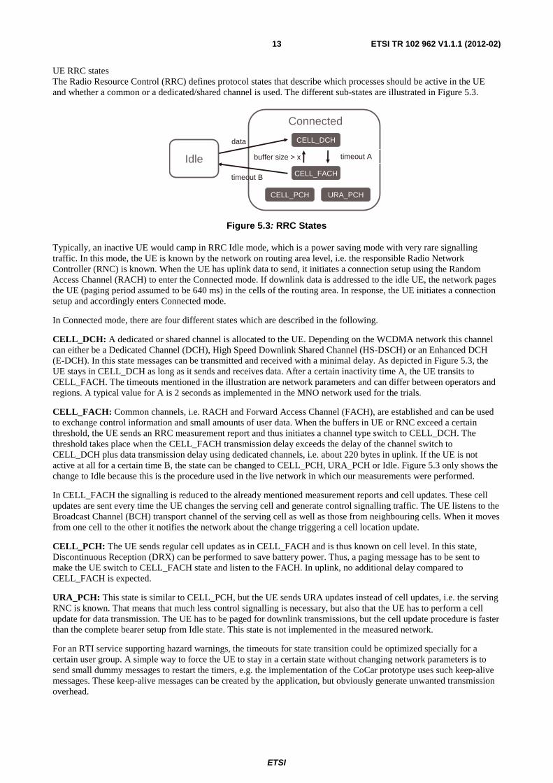
UE RRC states The Radio Resource Control (RRC) defines protocol states that describe which processes should be active in the UE and whether a common or a dedicated/shared channel is used. The different sub-states are illustrated in Figure 5.3.
CELL_DCH
CELL_FACH
URA_PCHCELL_PCH
timeout Abuffer size > x
data
timeout B
Connected
Idle
Figure 5.3: RRC States
Typically, an inactive UE would camp in RRC Idle mode, which is a power saving mode with very rare signalling traffic. In this mode, the UE is known by the network on routing area level, i.e. the responsible Radio Network Controller (RNC) is known. When the UE has uplink data to send, it initiates a connection setup using the Random Access Channel (RACH) to enter the Connected mode. If downlink data is addressed to the idle UE, the network pages the UE (paging period assumed to be 640 ms) in the cells of the routing area. In response, the UE initiates a connection setup and accordingly enters Connected mode.
In Connected mode, there are four different states which are described in the following.
CELL_DCH: A dedicated or shared channel is allocated to the UE. Depending on the WCDMA network this channel can either be a Dedicated Channel (DCH), High Speed Downlink Shared Channel (HS-DSCH) or an Enhanced DCH (E-DCH). In this state messages can be transmitted and received with a minimal delay. As depicted in Figure 5.3, the UE stays in CELL_DCH as long as it sends and receives data. After a certain inactivity time A, the UE transits to CELL_FACH. The timeouts mentioned in the illustration are network parameters and can differ between operators and regions. A typical value for A is 2 seconds as implemented in the MNO network used for the trials.
CELL_FACH: Common channels, i.e. RACH and Forward Access Channel (FACH), are established and can be used to exchange control information and small amounts of user data. When the buffers in UE or RNC exceed a certain threshold, the UE sends an RRC measurement report and thus initiates a channel type switch to CELL_DCH. The threshold takes place when the CELL_FACH transmission delay exceeds the delay of the channel switch to CELL_DCH plus data transmission delay using dedicated channels, i.e. about 220 bytes in uplink. If the UE is not active at all for a certain time B, the state can be changed to CELL_PCH, URA_PCH or Idle. Figure 5.3 only shows the change to Idle because this is the procedure used in the live network in which our measurements were performed.
In CELL_FACH the signalling is reduced to the already mentioned measurement reports and cell updates. These cell updates are sent every time the UE changes the serving cell and generate control signalling traffic. The UE listens to the Broadcast Channel (BCH) transport channel of the serving cell as well as those from neighbouring cells. When it moves from one cell to the other it notifies the network about the change triggering a cell location update.
CELL_PCH: The UE sends regular cell updates as in CELL_FACH and is thus known on cell level. In this state, Discontinuous Reception (DRX) can be performed to save battery power. Thus, a paging message has to be sent to make the UE switch to CELL_FACH state and listen to the FACH. In uplink, no additional delay compared to CELL_FACH is expected.
URA_PCH: This state is similar to CELL_PCH, but the UE sends URA updates instead of cell updates, i.e. the serving RNC is known. That means that much less control signalling is necessary, but also that the UE has to perform a cell update for data transmission. The UE has to be paged for downlink transmissions, but the cell update procedure is faster than the complete bearer setup from Idle state. This state is not implemented in the measured network.
For an RTI service supporting hazard warnings, the timeouts for state transition could be optimized specially for a certain user group. A simple way to force the UE to stay in a certain state without changing network parameters is to send small dummy messages to restart the timers, e.g. the implementation of the CoCar prototype uses such keep-alive messages. These keep-alive messages can be created by the application, but obviously generate unwanted transmission overhead.
ETSI
ETSI TR 102 962 V1.1.1 (2012-02) 14
5.2.2 HSPA unicast uplink delay
The UE can be in either Idle state (power saving state) or "Radio Resource Control (RRC) Connected" state. In Idle state, which is a power saving state, the connection setup will require 2 seconds to 2,5 seconds which disqualifies this state from further discussions as the total latency should not exceed one second. "RRC connected" includes three sub states that are to be considered, namely CELL_DCH (shared or dedicated channel) sub state, CELL_FACH (common channel) sub state and URA_PCH sub state.
• If the UE is in CELL_DCH or CELL_FACH sub state the total uplink transmission time is 100 ms to 178 ms.
• If the UE is in URA_PCH sub state about 300 ms has to be added to the above due to state channel switching to CELL_FACH sub state before start of transmission, i.e. the total time is 400 ms to 500 ms in total.
5.2.3 HSPA Unicast downlink delay
Similar to the above case, only UEs in "RRC connected" state have to be considered, as idle state is disqualified already on its uplink performance.
For UEs in CELL_DCH and CELL_FACH sub state values are similar to those for uplink transmission presented above. Furthermore:
• For networks based on R6 and later releases as many as about 1 000 UEs per cell in CELL_DCH sub state can be reached with a message.
• For networks based on R7 and later releases up to 2 000 UEs can be reached with a message.
For UEs in URA_PCH, state channel switching requires 300 ms similar to the uplink case. Furthermore, paging is required and that takes another 160 ms (average value).
However, there are severe snags associated with the use of the CELL_DCH and CELL_FACH sub state:
• Continuous camping on CELL_DCH sub state can be allowed for a very limited number of devices depending on the product specification. Furthermore, switch down from CELL_DCH to CELL_FACH sub state normally takes place after a few seconds of no data transmission.
• The situation for CELL_FACH sub state is somewhat better than for CELL_DCH sub state. The maximum number of UEs allowed to remain in the CELL_FACHs sub-state is higher than the previous case but it is shared amongst all RBSs connected to the "Radio Network Controller" (RNC) node which controls the RBSs. This will anyway prevent a widespread use of it for unicast ITS message distribution. Switching down to URA_PCH sub state or idle state takes place typically after ~30 seconds of "quietness".
• Finally, the number of stations being simultaneously in the URA_PCHs sub-state has also an upper limit.
In conclusion, provided that UEs are permanently in CELL_DCH or CELL_FACH sub-state, the total latency for unicast V2V or V2I is not an issue. The issue is rather the limitations imposed on the number of UEs simultaneously in CELL_DCH and CELL_FACH.
5.2.4 Downlink distribution over HSPA ETWS
ETWS in WCDMA shows a couple of major obstacles for using it for C-ITS purposes:
• Reception of ETWS notification in CELL_FACH and CELL_DCH sub-state is not standardized and is up to UE implementation/capability and operator support.
• The ETWS primary notification carries no data and a secondary notification will always be required for any message.
The first obstacle could be removed by a minor change in the standard if major operators would drive the issue but the second is worse as the lowest possible total latency will be around two seconds. Whether an extended primary notification able to forward a message would be possible to introduce, technically and standardization wise, has not been investigated.
ETSI
ETSI TR 102 962 V1.1.1 (2012-02) 15
5.2.5 CoCar trials and results
5.2.5.1 System overview
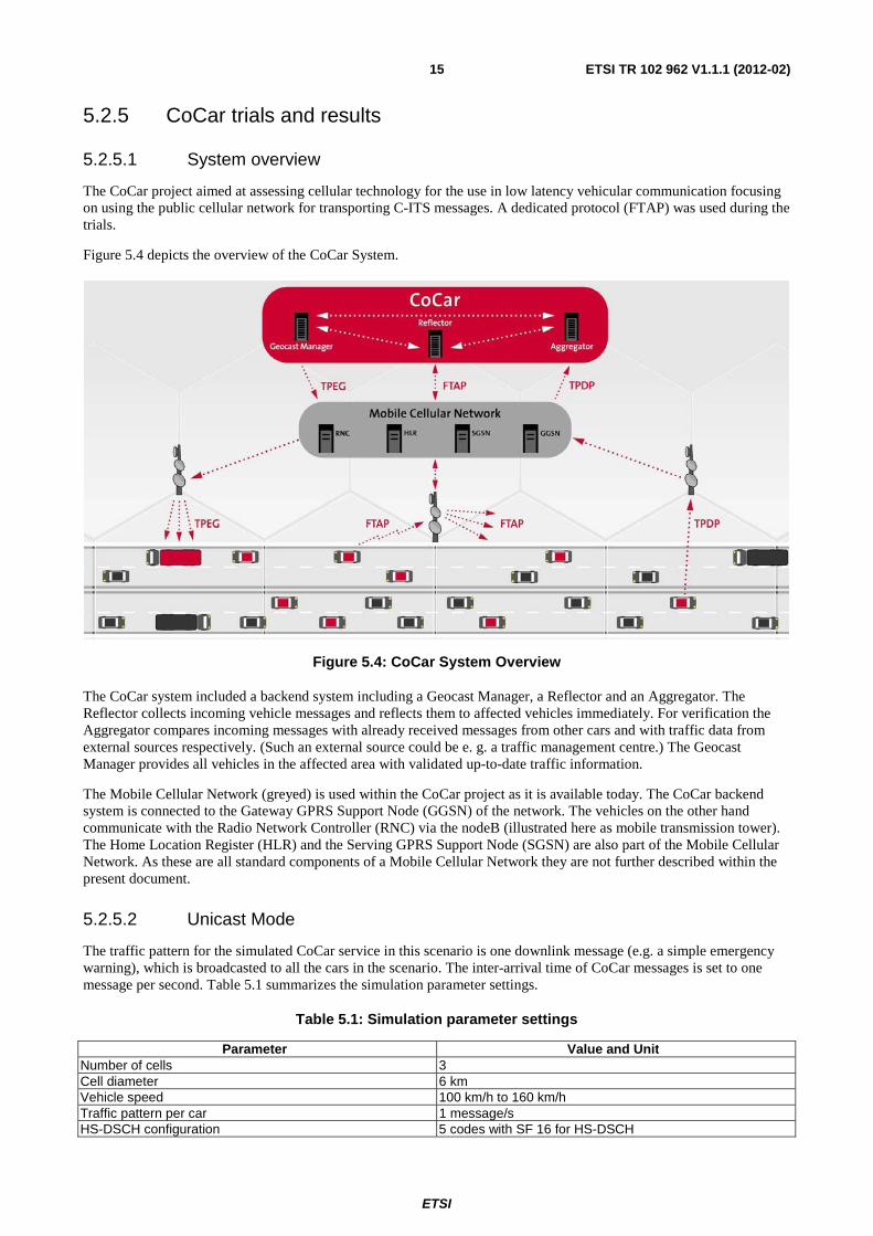
The CoCar project aimed at assessing cellular technology for the use in low latency vehicular communication focusing on using the public cellular network for transporting C-ITS messages. A dedicated protocol (FTAP) was used during the trials.
Figure 5.4 depicts the overview of the CoCar System.
Figure 5.4: CoCar System Overview
The CoCar system included a backend system including a Geocast Manager, a Reflector and an Aggregator. The Reflector collects incoming vehicle messages and reflects them to affected vehicles immediately. For verification the Aggregator compares incoming messages with already received messages from other cars and with traffic data from external sources respectively. (Such an external source could be e. g. a traffic management centre.) The Geocast Manager provides all vehicles in the affected area with validated up-to-date traffic information.
The Mobile Cellular Network (greyed) is used within the CoCar project as it is available today. The CoCar backend system is connected to the Gateway GPRS Support Node (GGSN) of the network. The vehicles on the other hand communicate with the Radio Network Controller (RNC) via the nodeB (illustrated here as mobile transmission tower). The Home Location Register (HLR) and the Serving GPRS Support Node (SGSN) are also part of the Mobile Cellular Network. As these are all standard components of a Mobile Cellular Network they are not further described within the present document.
5.2.5.2 Unicast Mode
The traffic pattern for the simulated CoCar service in this scenario is one downlink message (e.g. a simple emergency warning), which is broadcasted to all the cars in the scenario. The inter-arrival time of CoCar messages is set to one message per second. Table 5.1 summarizes the simulation parameter settings.
Table 5.1: Simulation parameter settings
Parameter Value and Unit Number of cells 3 Cell diameter 6 km Vehicle speed 100 km/h to 160 km/h Traffic pattern per car 1 message/s HS-DSCH configuration 5 codes with SF 16 for HS-DSCH
ETSI
ETSI TR 102 962 V1.1.1 (2012-02) 16
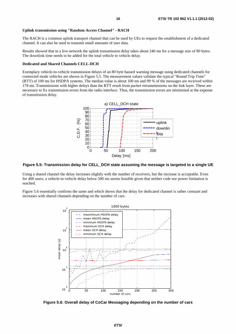
Uplink transmission using "Random Access Channel" - RACH
The RACH is a common uplink transport channel that can be used by UEs to request the establishment of a dedicated channel. It can also be used to transmit small amounts of user data.
Results showed that in a live network the uplink transmission delay takes about 240 ms for a message size of 80 bytes. The downlink time needs to be added for the total vehicle to vehicle delay.
Dedicated and Shared Channels CELL-DCH
Exemplary vehicle-to-vehicle transmission delays of an 80 byte hazard warning message using dedicated channels for connected mode vehicles are shown in Figure 5.5. The measurement values validate the typical "Round Trip Time" (RTT) of 100 ms for HSDPA systems. The median value is about 100 ms and 99 % of the messages are received within 178 ms. Transmissions with higher delays than the RTT result from packet retransmissions on the link layer. These are necessary to fix transmission errors from the radio interface. Thus, the transmission errors are minimized at the expense of transmission delay.
0 50 100 150 2000
102030405060708090
100
C.D
.F.
[%
]
Delay [ms]
a) CELL_DCH state
Figure 5.5: Transmission delay for CELL_DCH state assuming the message is targeted to a single UE
Using a shared channel the delay increases slightly with the number of receivers, but the increase is acceptable. Even for 400 users, a vehicle-to-vehicle delay below 500 ms seems feasible given that neither code nor power limitation is reached.
Figure 5.6 essentially confirms the same and which shows that the delay for dedicated channel is rather constant and increases with shared channels depending on the number of cars.
Figure 5.6: Overall delay of CoCar Messaging depending on the number of cars
uplink downlink
total
ETSI
ETSI TR 102 962 V1.1.1 (2012-02) 17
Furthermore, it can be stated that dedicated channels exhibit higher delays than shared channels for small packet sizes as illustrated in Figure 5.7.
.
Figure 5.7: Overall delay of CoCar message depending on message size
Regarding capacity, the maximum number of users that can be served depends on the number of available codes in the downlink. For WCDMA based on release 99, that number is around 200 vehicles per cell. Given that, the requirements for a full deployment scenario with 300 or 400 vehicles per cell cannot be realized in a WCDMA network using constantly maintained DCHs, even if all codes are used for C-ITS.
Code limitations in HSDPA limits further the maximum number of vehicles in a cell to around 130 vehicles per cell.
However, systems have been optimized in release 6: In order to reduce the number of codes used for dedicated channels in HS mode, the "Fractional DPCH" (F-DPCH) has been introduced in release 6, which enables a very large number of cars per cell to be constantly connected, as long as they do not generate significantly high amounts of data traffic, which would lead to power limitation.
In conclusion: the measured transmission delay of about 100 ms to 300 ms from vehicle to vehicle with HSDPA fulfils the transmission delay requirement of many Car-to-Car applications. Using a shared channel the delay increases slightly with the number of receivers, but the increase is acceptable. DCH has a capacity of 200 vehicles per cell, while HSDPA has the lowest capacity limitations with a maximum number of 130 users per cell. HSPA with release 6 offers additional functionality that allows continuous connection to over to 1 000 users per cell. This means that enough cars could be connected constantly, even in a full deployment scenario.
It is also important to note that vehicles that use dedicated channels are continuously transmitting data. After a certain inactivity timeout, which depends on the cellular operator, the network initiates a state change to CELL-FACH.
Idle State
In order to save resources, today's networks are configured to keep non-active users in Idle mode. But the connection setup that is necessary before the data can be sent takes a lot of time compared to the mere transmission delay. Figure 5.8 shows the vehicle-to-vehicle delay for two vehicles that both perform a connection setup before they send and receive the data. In Idle mode as well as in states URA_PCH and CELL_PCH the UE needs to be paged in order to inform the UE about the upcoming message transmission. Thus, the transmission delay in downlink is much higher. For paging interval, typically around 640 ms, or an optimized period of 320 ms can be used for URA_PCH. The UE listens to paging indications periodically, where the period is configurable and depends on the number of UEs and on the number of allocated paging channels.
The vehicle-to-vehicle delay of about 5 s is not adequate for time critical messages sent from car to car.
ETSI
ETSI TR 102 962 V1.1.1 (2012-02) 18
0 2000 4000 60000
102030405060708090
100
C.D
.F.
[%
]Delay [ms]
b) Idle state
Figure 5.8: Transmission delay for Idle state assuming the message is targeted to a single UE
Common Channels CELL-FACH
The median vehicle-to-vehicle transmission delay in state CELL_FACH is about 320 ms on average as illustrated in Figure 5.9. The larger delays for this scenario are caused in the downlink. One characteristic of the CELL_FACH scenario is that if there is only one FACH available, the users get the message one after the other. In an exemplary scenario with 100 users, the last user would receive a 100 byte message after 3 seconds, assuming a 32 kbit/s FACH with a TTI of 10 ms (40 bytes per TTI) is used. So the delay of 320 ms is solely feasible for the first receiving user.
In order to avoid long delays and to provide sufficient system capacity, multiple FACHs can be operated in parallel, so that the message only needs to be transmitted to a subset of the UEs on each FACH. Going back to the previous example and according to the calculation in the last paragraph, three 32 kbit/s FACHs enable a maximum transmission delay of one second to 100 users. As a trade-off, codes have to be permanently allocated for all FACHs. One advantage here is that existing systems can be used to realize this scenario. However, knowing that MBMS uses a FACH for broadcast transmission, the unicast solution sending the same content several times into the same cell via unicast transmission, the CELL_FACH solution appears very inefficient. Thus, this scenario is especially suitable for a scenario with few connected vehicles.
In general, the distribution of small messages in CELL_FACH is more resource efficient than in CELL_DCH, but the transmission delay increases with the number of users. This impact can be reduced when applying Enhanced CELL_FACH, introduced in Release 7. In this state, HSDPA is activated also for users in CELL_FACH and throughputs of 300 kbit/s to 500 kbit/s can be achieved in downlink. This state enables fast downlink transmission in CELL_FACH and in addition allows for an uninterrupted downlink data transmission during the switch to CELL_DCH should that take place.
0 100 200 300 400 5000
102030405060708090
100
C.D
.F.
[%
]
Delay [ms]
c) Cell_FACH state
uplink
downlink
total
Figure 5.9: Transmission delay for Cell_FACH state assuming the message is targeted to a single UE
In conclusion: CELL_FACH state has the advantage not to block radio resources when no messages are transmitted. This kind of resource consumption is beneficial for small and relatively rare hazard warnings. Enhanced CELL_FACH even improves the transmission in CELL_FACH state and thereby is expected to achieve similar transmission delays to those of HSDPA in downlink. However, the transmission delay increases with the number of users, because messages are transmitted sequentially in both, CELL_FACH and Enhanced CELL_FACH. Thus, this mode only makes sense up to about 30 (to maximum 50) users per cell, assuming additional FACH for performance improvements.
uplink downlink
total
ETSI
ETSI TR 102 962 V1.1.1 (2012-02) 19
In general it seems a waste of resources to send exactly the same message over several unicast connections to users that are probably even located in the same or a neighbouring cell. Thus, for a high number of equipped users, broadcast mechanisms (MBMS) offer a better alternative.
5.2.5.3 Broadcast Mode
MBMS Service setup
In MBMS four new channels are introduced, and studied during the CoCar trials:
• The MBMS logical channel for user data is the "MBMS Traffic Channel" (MTCH). It is mapped on the FACH, which uses the S-CCPCH, and typically supports data rates of 64 kbit/s, 128 kbit/s, or 256 kbit/s.
• The "MBMS Scheduling Channel" (MSCH), a control channel, provides information on the transmission time at which the data is scheduled on the MTCH.
• The "MBMS Control Channel" (MCCH), a control channel, contains transmission information concerning ongoing and upcoming MBMS sessions. Both are also mapped to a FACH.
• The "MBMS Notification Indicator Channel" (MICH), a control channel, notifies users about upcoming services and modifications on the MCCH.
A typical MBMS service consists of several sessions. First, the UE subscribes to the service, and whenever data is available the Broadcast Multicast Service Centre (BM-SC) starts a session. Then bearers are set up to distribute the data. In the broadcast case, this means that the session is first announced via broadcast control channels and after that the data channel can be established and used. This implementation is resource efficient in terms of transmission power and the UE is able to perform DRX to save battery power. Nevertheless, the "Session Start" and "MBMS Notification" phase take some time. The two phases take at least 5,5 s. Assuming for example a non-time critical multimedia service that is updated every few hours, this delay is acceptable, but for time critical traffic warnings this procedure should not be used.
To enable a broadcast channel with minimal transmission delays a "non-stop MBMS traffic safety service" should be configured. The user or vehicle can subscribe to it like to any other MBMS service. Then the vehicle joins the session and receives the distributed information. In order to avoid additional delays the resources for this service should be allocated permanently. The continuously maintained user data channel MTCH allows for immediate transmission of safety information. Thus, minimum delays for the downlink transmission can be realized.
This concept requires that the vehicle continuously reads information both from the control and the data channel, so that DRX cannot be applied. This means that the vehicle has higher DC power consumption than usual for MBMS services. Because we expect car-integrated communication units, this small additional DC power consumption should be a minor issue.
MBMS Service Area (MSA)
The MBMS Service Area (MSA) is defined as the area to which data of a specific MBMS session can be sent. The minimum size of one MSA is one cell. Each individual MBMS session is addressed to a Multicast or Broadcast Service Area which again can consist of one or more MSAs.
The composition of a MSA is kept in the RNC and defined as a relation between the cell identifiers of the service and an identifier for this MSA. At the start of a session the BM-SC addresses the user data to a list of predefined MSAs.
In WCDMA Release 8, MBMS makes it possible to setup separate user data streams within one single service. This is realized with Flow Identifiers as illustrated in Figure 5.10, in which the Broadcast Area could be e.g. the whole national network and the Local broadcast areas A, B and C are regions with different traffic information (1,2,3) whereas in each area only the relevant content is distributed.
ETSI
ETSI TR 102 962 V1.1.1 (2012-02) 20
Broadcast Service Area
Flow ID 1 in Local Broadcast
Area A
Broadcast Service Data Source
1 2 3 1 2 3
Flow ID 1,2 in Local
BroadcastArea B
Flow ID 3 in Local Broad-
cast Area C
1 2 3 Flow ID
Figure 5.10: Broadcast Service with different content data for different locations
Downlink Delay Measurements
Figure 5.11: Downlink Delays in MBMS
Figure 5.11 shows a breakdown of the different delays in downlink distribution. Table 5.2 provides a description of the different contributors to the downlink delay. As can be seen the worst case delay is 260 ms.
Table 5.2: Transmission delay elements in downlink
Time Delay [ms] Description
T1 6 Processing in RTI server: filtering, message generation, scheduling, etc.
T2 2 Server � BM-SC T3 1 Processing BM-SC
T4 40 ± 40 Time alignment (0-1 TTI) (BM-SC transmits one packet per TTI duration; not aligned with NodeB)
T5 2 BM-SC � GGSN T6 0,2 Processing GGSN T7 2 GGSN � RNC
T8 40 ± 40 RNC TTI alignment (0-1 TTI) [depends on time drift between BM-SC and RNC; could be minimized by synchronizing clocks]
T9 0,5 Processing RNC T10 3,1 RNC � NodeB T11 1 Processing NodeB T12 80 Message transmission (1 TTI) T13 1,5 Processing UE Total 179,3 ± 80 Delay RTI Server � UE
RTI Server GGSN RNC NodeB BM -SC UE
T1T2
T3
T5T4
T6 T7
T9 T10
T11T12
T13
T8
ETSI
ETSI TR 102 962 V1.1.1 (2012-02) 21
Vehicle-to-Vehicle Transmission Delay
The reception of an MBMS service is possible regardless of the RRC state of the UE. Also Idle UEs are able to receive an MBMS service.
The UE could stay in CELL_FACH or CELL_PCH to enable a fast uplink alert using the RACH without a time consuming channel switch or bearer setup. Adding the mean uplink transmission delay of 240 ms for a hazard warning transmission on RACH, the average vehicle-to-vehicle delay is about 420 ms. Considering the longest measured RACH transmissions up to 270 ms and the longest estimated broadcast delay of 260 ms the maximum estimated delay is 530 ms.
UEs that are not supposed to transmit any uplink data at all and could stay in Idle mode only receiving the MBMS service.
5.2.5.4 Final conclusions
Typically, an inactive UE would be in RRC Idle mode, which is a power saving mode with very rare signaling traffic. Given that connection setups from Idle mode introduce significant delays for the message delivery. Therefore, RRC states where data can be directly received by the UE are recommended.
The CELL_DCH state prior to UMTS with the DCH and the HS-DSCH enables reliable data transmission and offers the shortest transmission delays but are optimized for point-to-point traffic consisting of large data portions. Furthermore, the dedicated and shared channels discussed above do not provide enough capacity required for safety services in situations with dense traffic and 100 % penetration rate. As such, usage of dedicated channels and/or shared channels may not be recommended for full scale deployment unless radio resources are allocated to ITS only.
In contrast, the CELL_FACH state has the advantage not to block radio resources when no messages are transmitted. This kind of resource consumption is beneficial for small and relatively rare hazard warnings. Allocating a certain amount of resources for the Common Channels RACH and FACH, the transmission delay could be further reduced. However, in this scenario the transmission delay increases with the number of users, because messages are transmitted sequentially. As such, usage of common channels is suitable for an introduction scenario. However, it is not recommended for a full scale deployment.
In both CELL_DCH and CELL_FACH it appears wasteful to transmit duplicates of messages to very many single users via unicast, either in parallel over different dedicated channels or sequentially on common channels. Usage of broadcast channel is thus recommended for these cases.
For regions with a high density of users, it is preferable to have a constantly monitored broadcast channel, realized with a permanent Multimedia Broadcast Multicast Service (MBMS) service. This scenario has the advantage that all users receive the message simultaneously with a low delay. However, to employ this continuous MBMS services, MBMS control channels need to be maintained even if no user data is transmitted.
The broadcast scenario has the additional advantage that messages can also be received by UEs in Idle mode. Therefore, UEs that are not supposed to send any uplink data can save power and resources, while they are still able to receive the service. Furthermore, the use of MBMS Service Areas (MSAs) enables area specific distribution of information. Thus, this scenario allows a comfortable service implementation, because directing the messages to a certain region might be more efficient than tracking and addressing every UE individually.
For FACH in downlink, between 40 ms and 100 ms are to be expected. For MBMS the downlink transmission delay from server to terminal is estimated to be 180 ms on average.
For Unicast transmission, in the uplink, the Random Access Channel (RACH) is the most suitable transport channel as it can be used without permanently reserving resources and its capacity is sufficiently high to transmit the message with a short delay. RACH uplink transmission delays from terminal to server vary between 40 ms and 250 ms, depending on the chosen network parameters.
For dedicated and shared channels mean values according to the "Round Trip Time" (RTT) vary between 80 ms and 150 ms which makes them faster. However UEs have to be continuously connected in CELL_DCH state which is not a viable option.
ETSI
ETSI TR 102 962 V1.1.1 (2012-02) 22
5.3 GSM / EDGE
5.3.1 Using GSM / GPRS uplink delay
The fastest way to transfer a message from the UE to the network is over a "Physical Data Channel" (PDCH) via a normal data transfer.
The data transfer should be as fast as possible and hence a number of optional features available today should be used:
• One phase access.
• Reduced latency.
Assuming that the UE is in 'GPRS attached' mode when the hazard is detected, the estimated time to transmit the message will be ~170 ms.
Data transfer over Abis interface is estimated to 20 ms. In fact this could be close to zero since the data will be transferred immediately from the BTS in case of packet Abis. However, during different load conditions this could vary but 20 ms is assumed enough. The same reasoning can be applied for sending the data over the Gb/Gn interface and to the server.
Figure 5.12: Time to send UL data over GSM/GPRS
Thus, the total time for transmission of an ITS message is estimated to 210 ms as can be seen in Figure 5.12.
5.3.2 Downlink distribution over GSM / GPRS ETWS
ETWS is assumed to be realized as an SMSCB to the BSC and from there on transported on channels to the UE depending on the current UE state from an air interface prospective.
UE in idle mode: In this case the message is sent over the paging channel. A UE listens for pages only in the paging group to which it belongs. In this case, UEs are assumed to belong to the most aggressive paging group to minimize latency. This implies increased battery consumption but this is not assumed to be a problem for vehicle mounted UEs. The average latency for reception of a RHW message is ~222 ms.
UE in dedicated mode: If the UE is in dedicated or packet transfer mode the transfer of the information should be done via an application PDU (APDU) [i.36] and [i.19] or packet APDU. The APDU can contain more than 56 bytes so one APDU/packet APDU will transfer the complete RHW. The APDU / packet APDU can be prioritized in the BSC so the information is transferred as fast as possible. This means that it will be transferred faster than for a UE in idle mode under all circumstances.
ETSI
ETSI TR 102 962 V1.1.1 (2012-02) 23
5.3.3 Downlink distribution over GSM / GPRS in unicast
The unicast case is handled via a normal data transfer that includes:
• Page.
• Channel request.
• Immediate assignment.
• DL data.
In reality there will also be acknowledgements on the UL but these are not counted for because a) The use of improved Ack/Nack might remove them, b) They will be performed on the UL at the same time as other ITS-Ss might perform their DL transfer. The paging latency depends on the paging group to which the UE belongs. With the default setting the average latency will be 706 ms and with the most aggressive (and most battery consuming) 235 ms.
As message sending goes on in parallel to a number of UEs the above mentioned latency contributions should not be added when calculating the time to transmit to a certain number of UEs. The complete results are shown in Table 5.3.
Table 5.3: Total UE to UE delay = UL + DL latency when using GSM unicast
MSs Data UL Page: Data DL Abis Time MFRMS=2 MFRMS=6
1 210 235 705 30 20 495 10 210 470 1 410 30 20 730 20 210 940 1 410 60 20 1 230 30 210 940 1 410 60 20 1 230 40 210 1 410 1 410 90 20 1 730 50 210 1 410 1 410 120 20 1 760 60 210 1 880 2 820 120 20 2 230 70 210 1 880 2 820 150 20 2 260 80 210 2 350 2 820 150 20 2 730 90 210 2 350 2 820 180 20 2 760
100 210 2 820 2 820 210 20 3 260
The following assumptions have been used in the above calculation:
• 56 bytes data + 8 bytes UDP header;
• MCS3 used for data transmission;
• EPDCHs occupied on DL for 100 ms per UE;
• 20 EPDCHs, 80 % of these are unoccupied.
5.4 LTE
5.4.1 Technology overview
Often referred to as the fourth generation (4G) of mobile networks, LTE ("High speed OFDM Packet Access", HSOPA) describes a new radio access technology. LTE required an evolved packet core network as well. This is referred to as SAE, which is the name of the 3GPP work item on the core network development and evolution. The work on LTE/SAE started in 2004. LTE was completed in release 8 standard.
LTE is optimized for IP based services providing high data rates and low access delays. One core requirement for LTE was to achieve data rates of at least 100 Mbit/s in downlink, and 50 Mbit/s in uplink for systems operating on a 20 MHz carrier. In fact, with 20 MHz of spectrum allocation, the LTE technology is able to reach much higher data rates. The physical layer technology allows over 300 Mbit/s. Typical bitrates per user will be around 30 Mbit/s.
ETSI
ETSI TR 102 962 V1.1.1 (2012-02) 24
The radio interface is based on "Orthogonal Frequency Division Multiple Access" (OFDMA) in downlink and on "Single Carrier Frequency Division Multiple Access" (SC-FDMA) in uplink. LTE supports multi-antenna techniques such as "Multiple-input and multiple-output" (MIMO) and beam forming to increase peak and cell edge bit rates respectively.
Defined by the SAE work group, the Evolved Packet Core (EPC) consists of two new network nodes for the packet switched domain. The EPC introduces enhanced "Quality of Service" (QoS) handling as well as interoperability with non-3GPP access technologies. The system architecture consisting of LTE and EPC is denoted "Evolved Packet System" (EPS).
In the IP based EPS, the number of nodes and thus the number of interfaces in the network architecture was reduced. The flat system architecture, consisting only of the "Evolved NodeB" (eNodeB) and the Gateway (GW), contributes to the low system latency. The terminal to eNodeB RTT is in the order of 10 ms. In first deployments, end-to-end RTTs below 50 ms are expected. Beside significant improvements in data rates and latency, a more cost efficient network structure through a much simplified network structure has been achieved. Additionally the spectrum flexibility was improved, allowing LTE to operate in frequency blocks (carriers) of 1,25 MHz to 20 MHz and in frequency bands from 700 MHz to 2,6 GHz. LTE networks are currently operational and being rolled out in many countries and in different frequency bands.
The LTE standard will further enhanced in various releases Support for MBMS for EPC has been introduced in 3GPP rel.9 (see TS 136 300 [i.46]) along with enhancement of radio access, which through synchronous transmission of identical signals - referred to as MBSFN transmission - gives a further downlink performance step. The resulting feature is known as eMBMS and details about performances and applicability to the C-ITS case are provided in annex B.
5.4.2 Physical downlink control channel
The "Physical Downlink Control Channel" (PDCCH) carries downlink assignments and uplink grants. Its capacity depends on the number of OFDM symbols allocated to the control region and the channel quality of the addressed UEs within the control region. Link adaptation allows dynamic resource allocation for the PDCCH, and depending on the number of needed assignments/grants, the size of the control region can be dynamically chosen.
5.4.3 Physical uplink control channel
The "Physical Uplink Control Channel" (PUCCH) carries Channel Quality Indicators (CQI) used for link adaptation in the DL scheduling, UL Scheduling Requests (SR), and HARQ feedback, i.e. Acks or Nacks, as a response to DL data transmissions.
5.4.4 CoCarX Results
This simulation study is part of the CoCarX project and investigates the performance for cooperative vehicle services using LTE. Two basic use case examples are introduced that serve as reference applications for the performance analysis. For these traffic applications, two different message types were defined:
• Cooperative Awareness Messages (CAM) are periodically sent messages with relevance in a small area, e.g. intersection assistant. Therefore it can be assumed that the UE is in RRC connected mode.
• Decentralized Environmental Notifications (DEN) are event-triggered messages, e.g. Hazard Warnings. Consequently, the UE is expected to be in RRC idle mode.
This goal of the study was to identify the maximum number of cars that can be served in a cell for these exemplary traffic patterns so the vehicle to vehicle delay remains reasonable.
For the purpose of the study, it has been assumed that the cooperative vehicle service is deployed in an empty LTE system in order to obtain the system capacity for car-2-car communication. Background traffic with different QoS requirements would strongly influence the simulation results and shift the focus for further analysis.
Basic simulation parameters are summarized in Table 5.4.
ETSI
ETSI TR 102 962 V1.1.1 (2012-02) 25
Table 5.4: Simulation parameters
System band width 5 MHz DL UL + 5 MHz DL (FDD)
Network size 7 sites with 3 sectors/site � 21 cells
Intersite-distance (ISD) and carrier frequency Urban scenario: 500 m at 2 GHz; antenna tilt: 11 ° Rural scenario: 6 km at 800 MHz; antenna tilt: 1 °
Tx / Rx antennas 1 / 2 (SIMO)
Channel models 3GPP SCM 3D
PDCCH capacity Unlimited; 7 grants/assignments, 3 for DL, 4 for UL
CQI reporting period 40 ms (One CQI value for whole bandwidth)
Scheduling algorithm Round robin
User speed 13,9 m/s = 50 km/h (urban) 22,2 m/s = 80 km/h (rural)
CAM size 120 byte (excluding L2/L3 headers), RLC UM and including 28 byte of IP header (as resulting from IPV4 and UDP header)
DENM size 120 byte (excluding L2/L3 headers), RLC AM and including 28 byte of IP header (as resulting from IPV4 and UDP header)
5.4.4.1 System Overview
The system under test was essentially the same as in CoCar with the following additions:
GeoMessaging Back End Server: This server allows downlink dissemination of CAMs and DENMs to the proper vehicles. A geographic area of interest is covered by any number of smaller areas. Vehicles entering in a new area register themselves when they cross over to a new area allowing the backend server to know cars present in any area at all times and their IP addresses as well. The size of the areas can vary from application to application and as such provides considerable flexibility for targeting the vehicles of interest depending on the application.
Calculations presented in document 'An Optimized Grid-Based Geocasting Method for Cellular Mobile Networks' [i.5] show that the amount of data transmission required updating the database in the network is comparatively small. As an example for an urban scenario with a grid spacing of 2 kilometres, a vehicle with an average driving time of 4 hours per day generates a data traffic of as little as 350 kilobytes per month.
Session Support: This allows the vehicles to establish sessions for other services, e.g. infotainment.
Messaging Support: This allows support for unicast signalling to a vehicle based on the IP address of the vehicle which is learnt by the geomessaging server during the vehicle registration process when crossing over to a new area.
5.4.4.2 CAM Scenario
These periodically sent messages are only relevant in a small area e.g. intersection assistant. It is assumed therefore that the UE is in RRC connected mode.
Scenario 1: 10 messages per second – Uplink
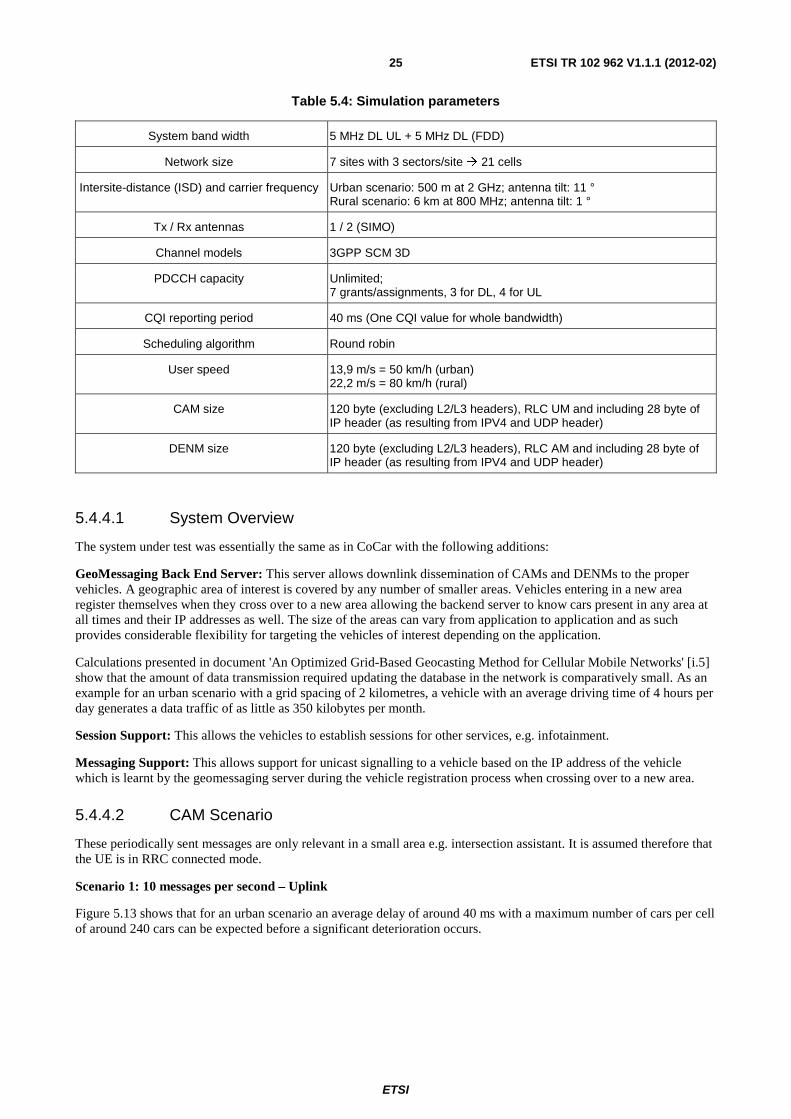
Figure 5.13 shows that for an urban scenario an average delay of around 40 ms with a maximum number of cars per cell of around 240 cars can be expected before a significant deterioration occurs.
ETSI
ETSI TR 102 962 V1.1.1 (2012-02) 26
.
0 50 100 150 200 250 300 3500
0.02
0.04
0.06
0.08
0.10
0.12
0.14
0.16
0.18
0.202 GHz, 500 m ISD
Average number of cars
Upl
ink
dela
y [s
]
No PDCCH mean
No PDCCH 95 %-tilePDCCH limit 7 mean
PDCCH limit 7 95 %-tile
Figure 5.13: Urban scenario, transmit rate = 10/s
Figure 5.14 shows for a rural scenario an average delay of around 40 ms with a maximum number of cars per cell around 190 cars can be expected before a significant deterioration occurs.
0 50 100 150 200 250 300 3500
0.02
0.04
0.06
0.08
0.10
0.12
0.14
0.16
0.18
0.20800 MHz, 6 km ISD
Average number of cars
Upl
ink
dela
y [s
]
No PDCCH mean
No PDCCH 95 %-tilePDCCH limit 7 mean
PDCCH limit 7 95 %-tile
Figure 5.14: Rural scenario, transmit rate = 10/s
PDCCH limitation @240 cars, 40 ms
PUSCH limitation
PDCCH limitation
@190 cars, 40 ms
PUSCH limitation
ETSI
ETSI TR 102 962 V1.1.1 (2012-02) 27
Scenario 2.1: 1 messages per second - Uplink
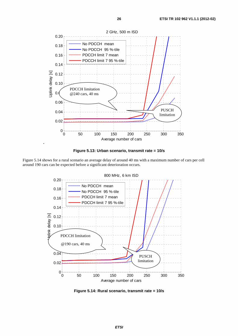
Figure 5.15 shows for a rural scenario an average delay of around 55 ms with a maximum number of cars per cell around 1 200 cars should be expected before a significant deterioration occurs.
It can be see here that the delay is slightly higher than in the previous scenario since the UE has to synchronize with the network which was not needed in the first scenario. It can be seen that the delay remains stable for up to 500 cars and steadily increases up to 1 200 cars. Beyond that there is steep increase in delay with increased car numbers.
0 200 400 600 800 1000 1200 1400 1600 1800 20000.03
0.04
0.05
0.06
0.07
0.08
0.09800 MHz, 6 km ISD
Average number of cars
Upl
ink
dela
y [s
]
No PDCCH mean
No PDCCH 95 %-tilePDCCH 7 mean
PDCCH 7 95 %-tile
Figure 5.15: Rural scenario, transmit rate = 1/s
Scenario 2.2: 1 message per second - Downlink
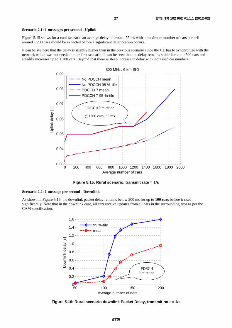
As shown in Figure 5.16, the downlink packet delay remains below 200 ms for up to 100 cars before it rises significantly. Note that in the downlink case, all cars receive updates from all cars in the surrounding area as per the CAM specification.
50 100 150 2000
0.2
0.4
0.6
0.8
1.0
1.2
1.4
1.6
Average number of cars
Dow
nlin
k de
lay
[s]
95 %-tile
mean
Figure 5.16: Rural scenario downlink Packet Delay, transmit rate = 1/s
PDSCH limitation
PDCCH limitation
@1200 cars, 55 ms
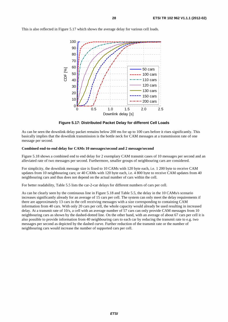
ETSI
ETSI TR 102 962 V1.1.1 (2012-02) 28
This is also reflected in Figure 5.17 which shows the average delay for various cell loads.
0 0.5 1.0 1.5 2.0 2.50
10
20
30
40
50
60
70
80
90
100
CD
F [
%]
Downlink delay [s]
50 cars100 cars
110 cars
120 cars
130 cars
150 cars200 cars
Figure 5.17: Distributed Packet Delay for different Cell Loads
As can be seen the downlink delay packet remains below 200 ms for up to 100 cars before it rises significantly. This basically implies that the downlink transmission is the bottle neck for CAM messages at a transmission rate of one message per second.
Combined end-to-end delay for CAMs 10 messages/second and 2 message/second
Figure 5.18 shows a combined end to end delay for 2 exemplary CAM transmit cases of 10 messages per second and an alleviated rate of two messages per second. Furthermore, smaller groups of neighbouring cars are considered.
For simplicity, the downlink message size is fixed to 10 CAMs with 120 byte each, i.e. 1 200 byte to receive CAM updates from 10 neighbouring cars; or 40 CAMs with 120 byte each, i.e. 4 800 byte to receive CAM updates from 40 neighbouring cars and thus does not depend on the actual number of cars within the cell.
For better readability, Table 5.5 lists the car-2-car delays for different numbers of cars per cell.
As can be clearly seen by the continuous line in Figure 5.18 and Table 5.5, the delay in the 10 CAMs/s scenario increases significantly already for an average of 15 cars per cell. The system can only meet the delay requirements if there are approximately 13 cars in the cell receiving messages with a size corresponding to containing CAM information from 40 cars. With only 20 cars per cell, the whole capacity would already be used resulting in increased delay. At a transmit rate of 10/s, a cell with an average number of 57 cars can only provide CAM messages from 10 neighbouring cars as shown by the dashed-dotted line. On the other hand, with an average of about 67 cars per cell it is also possible to provide information from 40 neighbouring cars to each car by reducing the transmit rate to e.g. two messages per second as depicted by the dashed curve. Further reduction of the transmit rate or the number of neighbouring cars would increase the number of supported cars per cell.
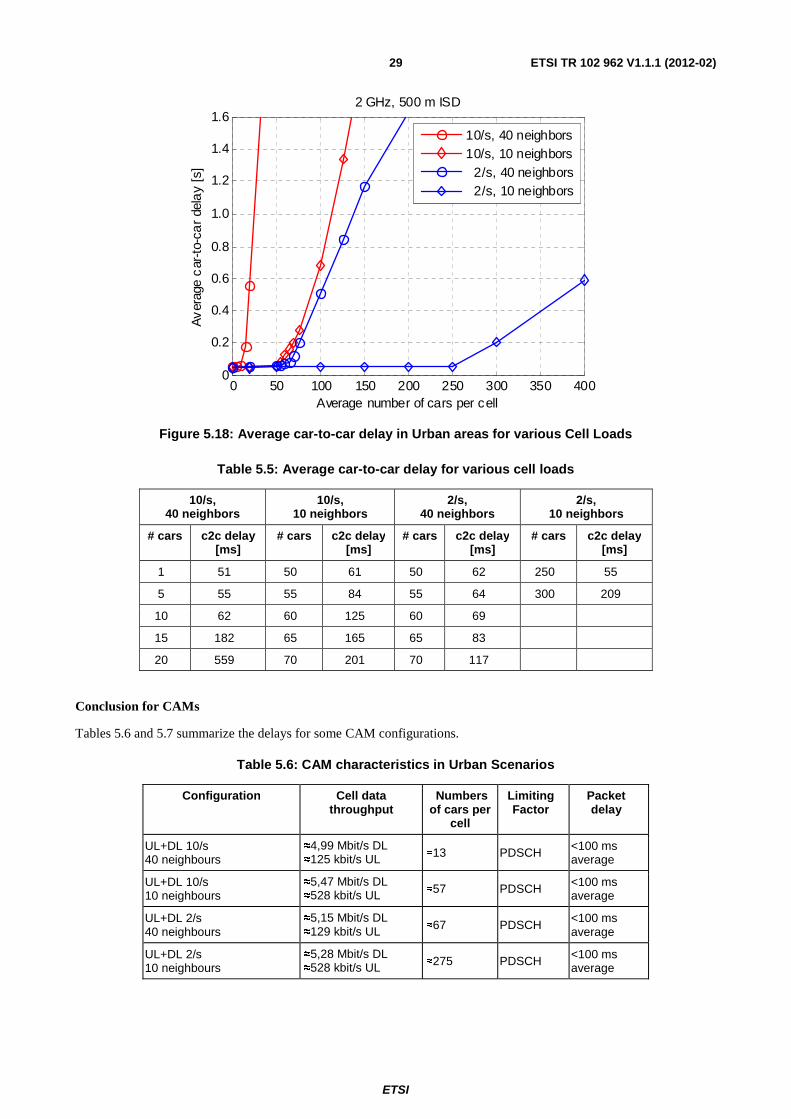
ETSI
ETSI TR 102 962 V1.1.1 (2012-02) 29
0 50 100 150 200 250 300 350 4000
0.2
0.4
0.6
0.8
1.0
1.2
1.4
1.6
Av
erag
e c
ar-t
o-ca
r de
lay
[s]
2 GHz, 500 m ISD
Average number of cars per cell
10/s, 40 neighbors10/s, 10 neighbors 2/s, 40 neighbors 2/s, 10 neighbors
Figure 5.18: Average car-to-car delay in Urban areas for various Cell Loads
Table 5.5: Average car-to-car delay for various cell loads
10/s, 40 neighbors
10/s, 10 neighbors
2/s, 40 neighbors
2/s, 10 neighbors
# cars c2c delay [ms]
# cars c2c delay [ms]
# cars c2c delay [ms]
# cars c2c delay [ms]
1 51 50 61 50 62 250 55
5 55 55 84 55 64 300 209
10 62 60 125 60 69
15 182 65 165 65 83
20 559 70 201 70 117
Conclusion for CAMs
Tables 5.6 and 5.7 summarize the delays for some CAM configurations.
Table 5.6: CAM characteristics in Urban Scenarios
Configuration Cell data throughput
Numbers of cars per
cell
Limiting Factor
Packet delay
UL+DL 10/s 40 neighbours
≈4,99 Mbit/s DL ≈125 kbit/s UL ≈13 PDSCH <100 ms
average
UL+DL 10/s 10 neighbours
≈5,47 Mbit/s DL ≈528 kbit/s UL ≈57 PDSCH <100 ms
average
UL+DL 2/s 40 neighbours
≈5,15 Mbit/s DL ≈129 kbit/s UL ≈67 PDSCH
<100 ms average
UL+DL 2/s 10 neighbours
≈5,28 Mbit/s DL ≈528 kbit/s UL ≈275 PDSCH <100 ms
average
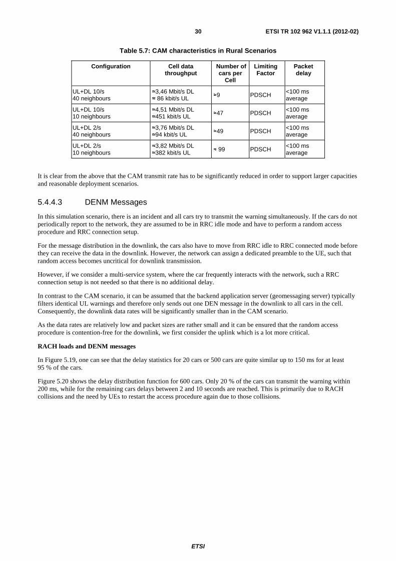
ETSI
ETSI TR 102 962 V1.1.1 (2012-02) 30
Table 5.7: CAM characteristics in Rural Scenarios
Configuration Cell data throughput
Number of cars per
Cell
Limiting Factor
Packet delay
UL+DL 10/s 40 neighbours
≈3,46 Mbit/s DL ≈ 86 kbit/s UL ≈9 PDSCH <100 ms
average
UL+DL 10/s 10 neighbours
≈4,51 Mbit/s DL ≈451 kbit/s UL ≈47 PDSCH <100 ms
average
UL+DL 2/s 40 neighbours
≈3,76 Mbit/s DL ≈94 kbit/s UL ≈49 PDSCH <100 ms
average
UL+DL 2/s 10 neighbours
≈3,82 Mbit/s DL ≈382 kbit/s UL ≈ 99 PDSCH
<100 ms average
It is clear from the above that the CAM transmit rate has to be significantly reduced in order to support larger capacities and reasonable deployment scenarios.
5.4.4.3 DENM Messages
In this simulation scenario, there is an incident and all cars try to transmit the warning simultaneously. If the cars do not periodically report to the network, they are assumed to be in RRC idle mode and have to perform a random access procedure and RRC connection setup.
For the message distribution in the downlink, the cars also have to move from RRC idle to RRC connected mode before they can receive the data in the downlink. However, the network can assign a dedicated preamble to the UE, such that random access becomes uncritical for downlink transmission.
However, if we consider a multi-service system, where the car frequently interacts with the network, such a RRC connection setup is not needed so that there is no additional delay.
In contrast to the CAM scenario, it can be assumed that the backend application server (geomessaging server) typically filters identical UL warnings and therefore only sends out one DEN message in the downlink to all cars in the cell. Consequently, the downlink data rates will be significantly smaller than in the CAM scenario.
As the data rates are relatively low and packet sizes are rather small and it can be ensured that the random access procedure is contention-free for the downlink, we first consider the uplink which is a lot more critical.
RACH loads and DENM messages
In Figure 5.19, one can see that the delay statistics for 20 cars or 500 cars are quite similar up to 150 ms for at least 95 % of the cars.
Figure 5.20 shows the delay distribution function for 600 cars. Only 20 % of the cars can transmit the warning within 200 ms, while for the remaining cars delays between 2 and 10 seconds are reached. This is primarily due to RACH collisions and the need by UEs to restart the access procedure again due to those collisions.
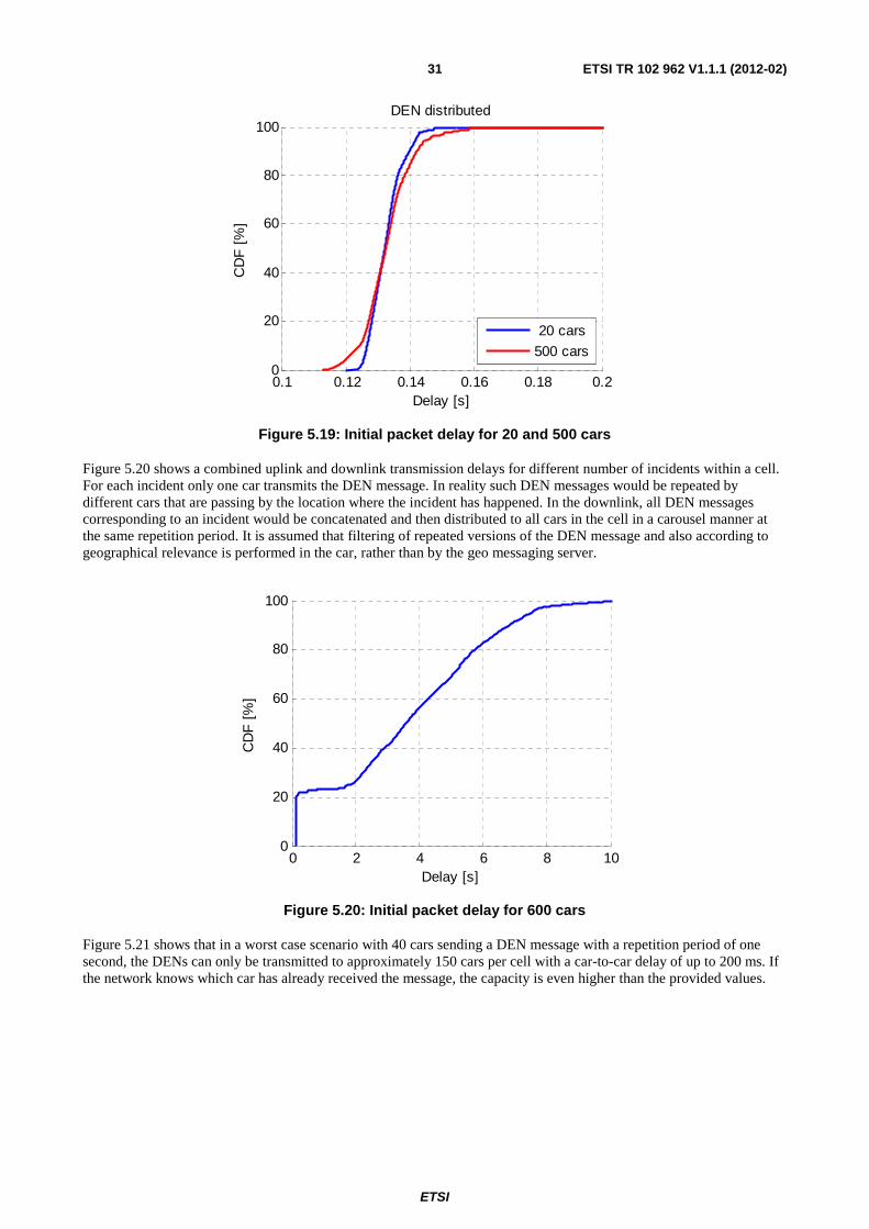
ETSI
ETSI TR 102 962 V1.1.1 (2012-02) 31
0.1 0.12 0.14 0.16 0.18 0.20
20
40
60
80
100DEN distributed
CD
F [
%]
Delay [s]
20 cars
500 cars
Figure 5.19: Initial packet delay for 20 and 500 cars
Figure 5.20 shows a combined uplink and downlink transmission delays for different number of incidents within a cell. For each incident only one car transmits the DEN message. In reality such DEN messages would be repeated by different cars that are passing by the location where the incident has happened. In the downlink, all DEN messages corresponding to an incident would be concatenated and then distributed to all cars in the cell in a carousel manner at the same repetition period. It is assumed that filtering of repeated versions of the DEN message and also according to geographical relevance is performed in the car, rather than by the geo messaging server.
0 2 4 6 8 100
20
40
60
80
100
CD
F [
%]
Delay [s]
Figure 5.20: Initial packet delay for 600 cars
Figure 5.21 shows that in a worst case scenario with 40 cars sending a DEN message with a repetition period of one second, the DENs can only be transmitted to approximately 150 cars per cell with a car-to-car delay of up to 200 ms. If the network knows which car has already received the message, the capacity is even higher than the provided values.
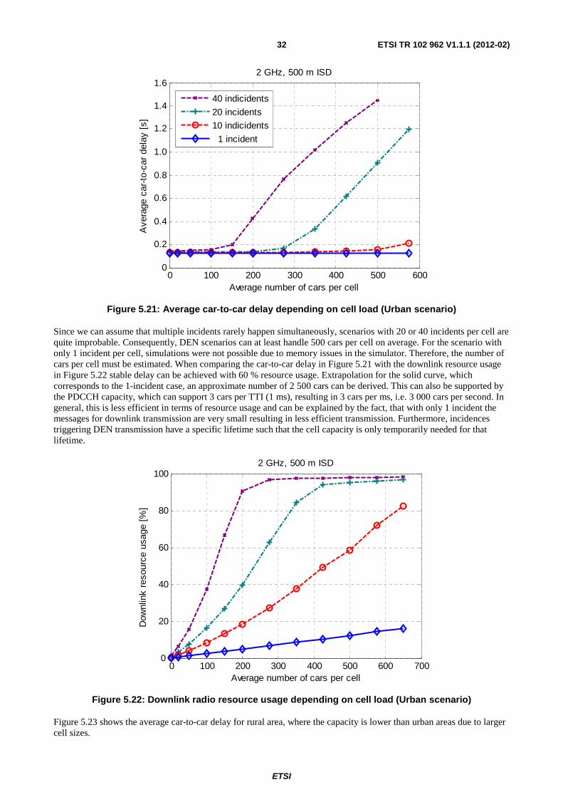
ETSI
ETSI TR 102 962 V1.1.1 (2012-02) 32
0 100 200 300 400 500 6000
0.2
0.4
0.6
0.8
1.0
1.2
1.4
1.6
Ave
rage
car
-to-
car
dela
y [s
]
2 GHz, 500 m ISD
Average number of cars per cell
40 indicidents
20 incidents
10 indicidents
1 incident
Figure 5.21: Average car-to-car delay depending on cell load (Urban scenario)
Since we can assume that multiple incidents rarely happen simultaneously, scenarios with 20 or 40 incidents per cell are quite improbable. Consequently, DEN scenarios can at least handle 500 cars per cell on average. For the scenario with only 1 incident per cell, simulations were not possible due to memory issues in the simulator. Therefore, the number of cars per cell must be estimated. When comparing the car-to-car delay in Figure 5.21 with the downlink resource usage in Figure 5.22 stable delay can be achieved with 60 % resource usage. Extrapolation for the solid curve, which corresponds to the 1-incident case, an approximate number of 2 500 cars can be derived. This can also be supported by the PDCCH capacity, which can support 3 cars per TTI (1 ms), resulting in 3 cars per ms, i.e. 3 000 cars per second. In general, this is less efficient in terms of resource usage and can be explained by the fact, that with only 1 incident the messages for downlink transmission are very small resulting in less efficient transmission. Furthermore, incidences triggering DEN transmission have a specific lifetime such that the cell capacity is only temporarily needed for that lifetime.
0 100 200 300 400 500 600 7000
20
40
60
80
1002 GHz, 500 m ISD
Average number of cars per cell
Dow
nlin
k re
sour
ce u
sage
[%
]
Figure 5.22: Downlink radio resource usage depending on cell load (Urban scenario)
Figure 5.23 shows the average car-to-car delay for rural area, where the capacity is lower than urban areas due to larger cell sizes.
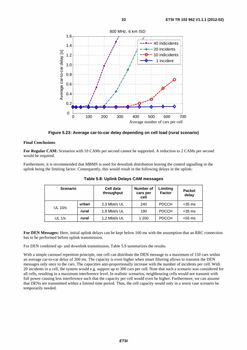
ETSI
ETSI TR 102 962 V1.1.1 (2012-02) 33
0 100 200 300 400 500 600 7000
0.2
0.4
0.6
0.8
1.0
1.2
1.4
1.6800 MHz, 6 km ISD
Ave
rage
car
-to-
car
dela
y [s
]
40 indicidents
20 incidents10 indicidents
1 incident
Figure 5.23: Average car-to-car delay depending on cell load (rural scenario)
Final Conclusions
For Regular CAM: Scenarios with 10 CAMs per second cannot be supported. A reduction to 2 CAMs per second would be required.
Furthermore, it is recommended that MBMS is used for downlink distribution leaving the control signalling in the uplink being the limiting factor. Consequently, this would result in the following delays in the uplink:
Table 5.8: Uplink Delays CAM messages
Scenario Cell data throughput
Number of cars per
cell
Limiting Factor Packet
delay
UL 10/s urban 2,3 Mbit/s UL 240 PDCCH <35 ms
rural 1,8 Mbit/s UL 190 PDCCH <35 ms
UL 1/s rural 1,2 Mbit/s UL 1 200 PDCCH <55 ms
For DEN Messages: Here, initial uplink delays can be kept below 160 ms with the assumption that an RRC connection has to be performed before uplink transmission.
For DEN combined up- and downlink transmission, Table 5.9 summarizes the results.
With a simple carousel repetition principle, one cell can distribute the DEN message to a maximum of 150 cars within an average car-to-car delay of 200 ms. The capacity is even higher when smart filtering allows to transmit the DEN messages only once to the cars. The capacities anti-proportionally increase with the number of incidents per cell. With 20 incidents in a cell, the system would e.g. support up to 300 cars per cell. Note that such a scenario was considered for all cells, resulting in a maximum interference level. In realistic scenarios, neighbouring cells would not transmit with full power causing less interference such that the capacity per cell would even be higher. Furthermore, we can assume that DENs are transmitted within a limited time period. Thus, the cell capacity would only in a worst case scenario be temporarily needed.
Average number of cars per cell
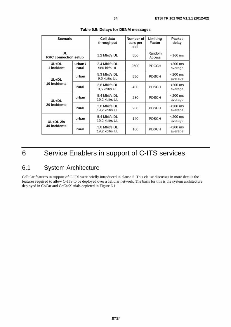
ETSI
ETSI TR 102 962 V1.1.1 (2012-02) 34
Table 5.9: Delays for DENM messages
Scenario Cell data throughput
Number of cars per
cell
Limiting Factor
Packet delay
UL RRC connection setup 1,2 Mbit/s UL 500 Random
Access <160 ms
UL+DL 1 incident
urban / rural
2,4 Mbit/s DL 960 bit/s UL 2500 PDCCH <200 ms
average
UL+DL 10 incidents
urban 5,3 Mbit/s DL 9,6 kbit/s UL 550 PDSCH <200 ms
average
rural 3,8 Mbit/s DL 9,6 kbit/s UL 400 PDSCH
<200 ms average
UL+DL 20 incidents
urban 5,4 Mbit/s DL 19,2 kbit/s UL 280 PDSCH <200 ms
average
rural 3,8 Mbit/s DL 19,2 kbit/s UL 200 PDSCH <200 ms
average
UL+DL 2/s 40 incidents
urban 5,4 Mbit/s DL 19,2 kbit/s UL 140 PDSCH <200 ms
average
rural 3,8 Mbit/s DL 19,2 kbit/s UL 100 PDSCH
<200 ms average
6 Service Enablers in support of C-ITS services
6.1 System Architecture Cellular features in support of C-ITS were briefly introduced in clause 5. This clause discusses in more details the features required to allow C-ITS to be deployed over a cellular network. The basis for this is the system architecture deployed in CoCar and CoCarX trials depicted in Figure 6.1.
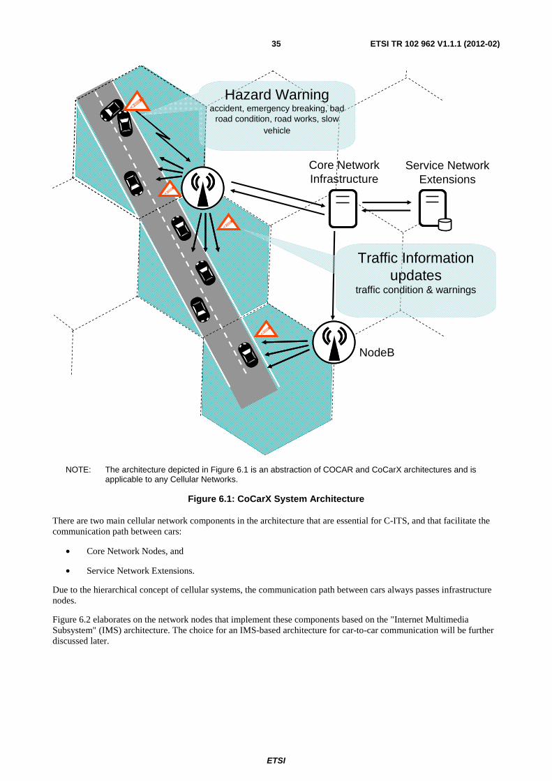
ETSI
ETSI TR 102 962 V1.1.1 (2012-02) 35
NodeB
�
�
�
�
Core NetworkInfrastructure
Service Network Extensions
Hazard Warningaccident, emergency breaking, bad
road condition, road works, slow vehicle
Traffic Information updates
traffic condition & warnings
NOTE: The architecture depicted in Figure 6.1 is an abstraction of COCAR and CoCarX architectures and is applicable to any Cellular Networks.
Figure 6.1: CoCarX System Architecture
There are two main cellular network components in the architecture that are essential for C-ITS, and that facilitate the communication path between cars:
• Core Network Nodes, and
• Service Network Extensions.
Due to the hierarchical concept of cellular systems, the communication path between cars always passes infrastructure nodes.
Figure 6.2 elaborates on the network nodes that implement these components based on the "Internet Multimedia Subsystem" (IMS) architecture. The choice for an IMS-based architecture for car-to-car communication will be further discussed later.
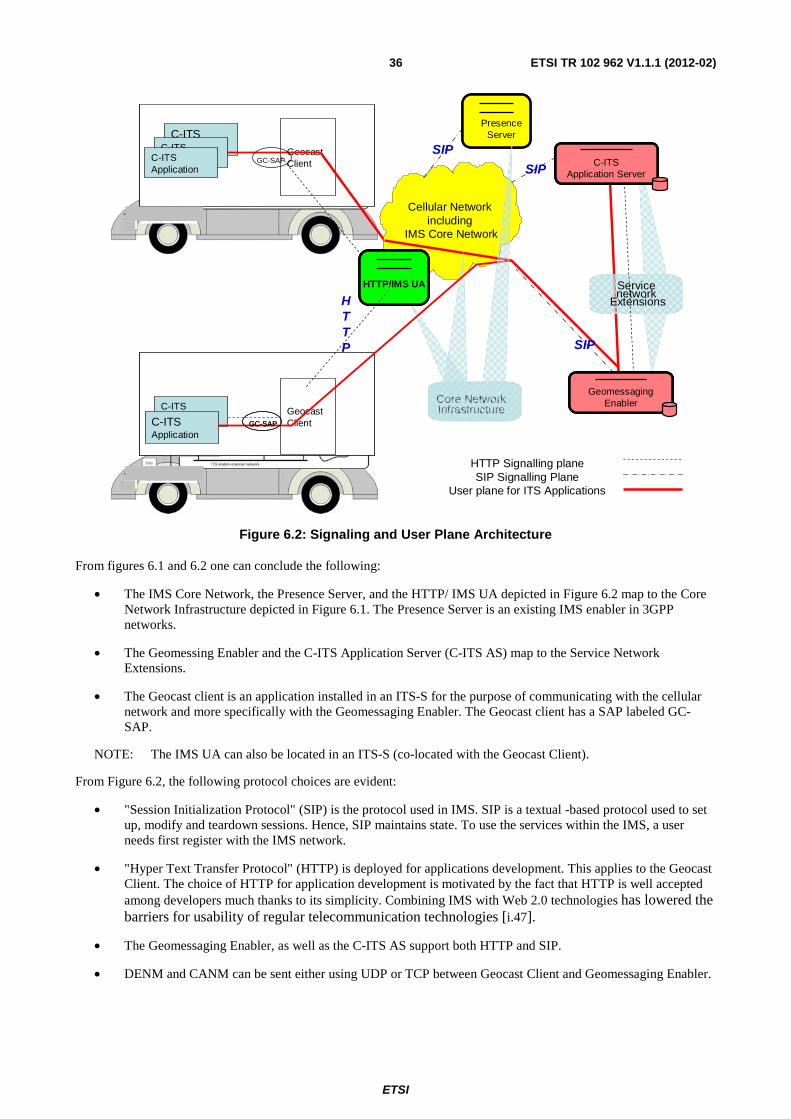
ETSI
ETSI TR 102 962 V1.1.1 (2012-02) 36
Geocast Client
C-ITSApplication
Cellular Network including
IMS Core Network
HTTP Signalling planeSIP Signalling Plane
User plane for ITS Applications
HTTP SIP
Geocast Client
C-ITS Application
Service network
Extensions
C-ITSApplication
Core Network Infrastructure
C-ITS Application
C-ITSApplication
SIP
PresenceServer
C-ITSApplication Server
C-ITSApplication Server
Geomessaging Enabler
Geomessaging Enabler
SIP
HTTP/IMS UAHTTP/IMS UA
GC-SAP
GC-SAPGC-SAP
Figure 6.2: Signaling and User Plane Architecture
From figures 6.1 and 6.2 one can conclude the following:
• The IMS Core Network, the Presence Server, and the HTTP/ IMS UA depicted in Figure 6.2 map to the Core Network Infrastructure depicted in Figure 6.1. The Presence Server is an existing IMS enabler in 3GPP networks.
• The Geomessing Enabler and the C-ITS Application Server (C-ITS AS) map to the Service Network Extensions.
• The Geocast client is an application installed in an ITS-S for the purpose of communicating with the cellular network and more specifically with the Geomessaging Enabler. The Geocast client has a SAP labeled GC-SAP.
NOTE: The IMS UA can also be located in an ITS-S (co-located with the Geocast Client).
From Figure 6.2, the following protocol choices are evident:
• "Session Initialization Protocol" (SIP) is the protocol used in IMS. SIP is a textual -based protocol used to set up, modify and teardown sessions. Hence, SIP maintains state. To use the services within the IMS, a user needs first register with the IMS network.
• "Hyper Text Transfer Protocol" (HTTP) is deployed for applications development. This applies to the Geocast Client. The choice of HTTP for application development is motivated by the fact that HTTP is well accepted among developers much thanks to its simplicity. Combining IMS with Web 2.0 technologies has lowered the barriers for usability of regular telecommunication technologies [i.47].
• The Geomessaging Enabler, as well as the C-ITS AS support both HTTP and SIP.
• DENM and CANM can be sent either using UDP or TCP between Geocast Client and Geomessaging Enabler.
ETSI
ETSI TR 102 962 V1.1.1 (2012-02) 37
The architecture has the following assumptions:
• Long polling is the mechanism used by a C-ITS application server to receive messages sent to it from vehicles or other ITS stations via the Geomessaging Enabler. For that purpose, the C-ITS AS uses a special HTTP GET request in order to receive messages. The GET request needs to use a persistent connection and so called long poll method. Upon every HTTP 200 OK reply the Geomessaging Enabler, the C-ITS AS is expected to issue a new request on the same connection. After a defined timeout there will be always an empty HTTP 200 OK reply if no messages are received by the Geomessaging Enabler. The C-ITS AS restarts the long polling process again.
The following is a brief description of the above network node elements.
6.1.1 C-ITS Application Server (C-ITS AS)
The C-ITS application server aggregates inputs received from several sources including vehicles on the road, road side units, as well as external information. All these inputs are then consolidated allowing the C-ITS AS to correlate incidents based on time, location and type of warning, so that it can derive a holistic picture of the road traffic with a higher level of information. An example may be a massive freeway pileup, where several different incident warnings arrive from nearly the same location and time. Based on the type of warnings, an intelligent reasoning algorithm may be able to classify all warnings to a single consolidated event.
Finally, once the consolidation process is completed, the C-ITS AS decides on the information that has to be disseminated and the target geographical area for the information. In the event that the incident and subsequently the information to be disseminated are considered relevant for a larger geographical area, the information is repackaged and sent to all users in the larger area. Information dissemination is accomplished using the Geomessaging Enabler for that purpose.
6.1.2 Geomessaging Enabler
The Geomessaging Enabler is essential for usage of cellular networks for information dissemination in C-ITS. The Geomessaging Enabler is responsible for distribution of e.g. CAM, DENM, and SPAT messages.
To that effect, the Geomessaging Enabler performs the following:
• Maintains a list of the geographical areas and their coordinates. Note that a relevance area maps into one or more geographical areas.
• Maintains a list of the identities of vehicles inside any geographical area. This requires that mobile ITS stations, e.g. vehicles, update the Geomessaging Enabler any time they leave their current geographical area and enter into a new area. This, in turn requires that these ITS stations be updated with the coordinates of their current geographical area so they can send the location update message once they leave that area.
The size of the distribution area or warning area of the CHWs should be adapted to the message type, the road traffic density, etc. Furthermore, the road topology could be taken into account to optimize the distribution area layout, e.g. the regions could follow the run of major roads.
It is also possible to have different distribution areas for different types of messages.
The Geomessaging Enabler supports two different addressing schemes for distribution purposes:
• unicast, and
• broadcast.
In case of unicast distribution, each vehicle within a specific geographical area receives the CHW message through an individual communication channel. In case of broadcast, all vehicles belonging to a broadcast area are addressed collectively, rather than individually. Hence, transmissions using broadcast channels are more efficient for a large number of recipients. For both distribution schemes, the vehicle system has to select only relevant warnings that will be indicated to the driver. This filter process interprets the location, time stamp and heading field of the received message.
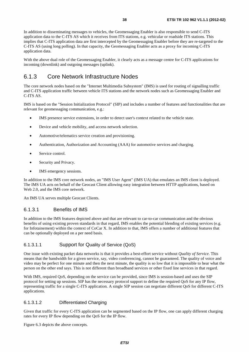
ETSI
ETSI TR 102 962 V1.1.1 (2012-02) 38
In addition to disseminating messages to vehicles, the Geomessaging Enabler is also responsible to send C-ITS application data to the C-ITS AS which it receives from ITS stations, e.g. vehicular or roadside ITS stations. This implies that C-ITS application data are first intercepted by the Geomessaging Enabler before they are re-targeted to the C-ITS AS (using long polling). In that capacity, the Geomessaging Enabler acts as a proxy for incoming C-ITS application data.
With the above dual role of the Geomessaging Enabler, it clearly acts as a message centre for C-ITS applications for incoming (downlink) and outgoing messages (uplink).
6.1.3 Core Network Infrastructure Nodes
The core network nodes based on the "Internet Multimedia Subsystem" (IMS) is used for routing of signalling traffic and C-ITS application traffic between vehicle ITS stations and the network nodes such as Geomessaging Enabler and C-ITS AS.
IMS is based on the "Session Initialization Protocol" (SIP) and includes a number of features and functionalities that are relevant for geomessaging communication, e.g.:
• IMS presence service extensions, in order to detect user's context related to the vehicle state.
• Device and vehicle mobility, and access network selection.
• Automotive/telematics service creation and provisioning.
• Authentication, Authorization and Accounting (AAA) for automotive services and charging.
• Service control.
• Security and Privacy.
• IMS emergency sessions.
In addition to the IMS core network nodes, an "IMS User Agent" (IMS UA) that emulates an IMS client is deployed. The IMS UA acts on behalf of the Geocast Client allowing easy integration between HTTP applications, based on Web 2.0, and the IMS core network.
An IMS UA serves multiple Geocast Clients.
6.1.3.1 Benefits of IMS
In addition to the IMS features depicted above and that are relevant to car-to-car communication and the obvious benefits of using existing proven standards in that regard, IMS enables the potential blending of existing services (e.g. for Infotainement) within the context of CoCar X. In addition to that, IMS offers a number of additional features that can be optionally deployed on a per need basis.
6.1.3.1.1 Support for Quality of Service (QoS)
One issue with existing packet data networks is that it provides a best-effort service without Quality of Service. This means that the bandwidth for a given service, say, video conferencing, cannot be guaranteed. The quality of voice and video may be perfect for one minute and then the next minute, the quality is so low that it is impossible to hear what the person on the other end says. This is not different than broadband services or other fixed line services in that regard.
With IMS, required QoS, depending on the service can be provided, since IMS is session-based and uses the SIP protocol for setting up sessions. SIP has the necessary protocol support to define the required QoS for any IP flow, representing traffic for a single C-ITS application. A single SIP session can negotiate different QoS for different C-ITS applications.
6.1.3.1.2 Differentiated Charging
Given that traffic for every C-ITS application can be segmented based on the IP flow, one can apply different charging rates for every IP flow depending on the QoS for the IP flow.
Figure 6.3 depicts the above concepts.
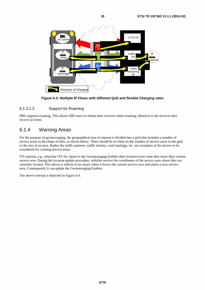
ETSI
ETSI TR 102 962 V1.1.1 (2012-02) 39
C-ITS AS
Traffic InfoSP
VideoStreaming
SP
driver
passenger
car-system
Data€
Data€
Data€
customer
Direction of Charging
Figure 6.3: Multiple IP Flows with different QoS and flexible Charging rates
6.1.3.1.3 Support for Roaming
IMS supports roaming. This allows IMS users to obtain their services while roaming, identical to the services they receive at home.
6.1.4 Warning Areas
For the purpose of geomessaging, the geographical area of interest is divided into a grid that includes a number of service areas in the shape of tiles, as shown below. There should be no limit on the number of service areas in the grid, or the size of an area. Rather the traffic patterns, traffic density, road topology, etc. are examples of the factors to be considered for creating service areas.
ITS stations, e.g. vehicular ITS-Ss, report to the Geomessaging Enabler their location every time they leave their current service area. During the location update procedure, vehicles receive the coordinates of the service area where they are currently located. This allows a vehicle to be aware when it leaves the current service area and enters a new service area. Consequently it can update the Geomessaging Enabler.
The above concept is depicted in Figure 6.4.
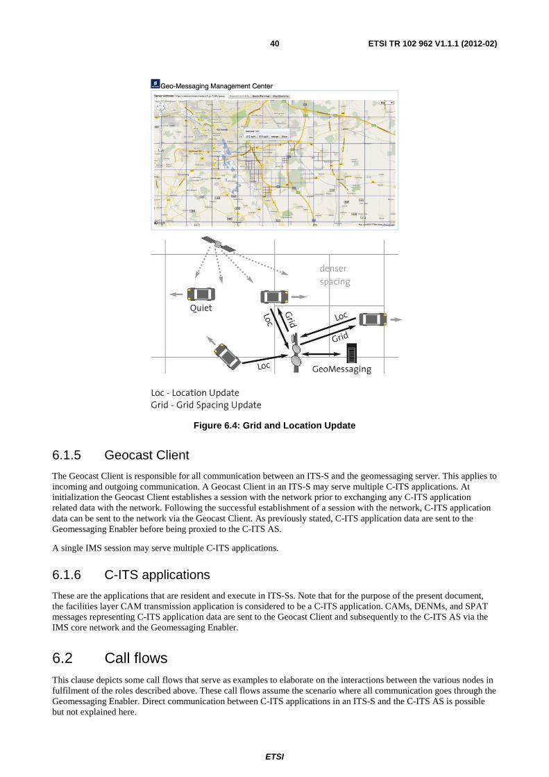
ETSI
ETSI TR 102 962 V1.1.1 (2012-02) 40
Figure 6.4: Grid and Location Update
6.1.5 Geocast Client
The Geocast Client is responsible for all communication between an ITS-S and the geomessaging server. This applies to incoming and outgoing communication. A Geocast Client in an ITS-S may serve multiple C-ITS applications. At initialization the Geocast Client establishes a session with the network prior to exchanging any C-ITS application related data with the network. Following the successful establishment of a session with the network, C-ITS application data can be sent to the network via the Geocast Client. As previously stated, C-ITS application data are sent to the Geomessaging Enabler before being proxied to the C-ITS AS.
A single IMS session may serve multiple C-ITS applications.
6.1.6 C-ITS applications
These are the applications that are resident and execute in ITS-Ss. Note that for the purpose of the present document, the facilities layer CAM transmission application is considered to be a C-ITS application. CAMs, DENMs, and SPAT messages representing C-ITS application data are sent to the Geocast Client and subsequently to the C-ITS AS via the IMS core network and the Geomessaging Enabler.
6.2 Call flows This clause depicts some call flows that serve as examples to elaborate on the interactions between the various nodes in fulfilment of the roles described above. These call flows assume the scenario where all communication goes through the Geomessaging Enabler. Direct communication between C-ITS applications in an ITS-S and the C-ITS AS is possible but not explained here.
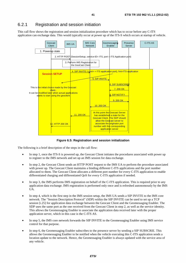
ETSI
ETSI TR 102 962 V1.1.1 (2012-02) 41
6.2.1 Registration and session initiation
This call flow shows the registration and session initialization procedure which has to occur before any C-ITS application can exchange data. This would typically occur at power up of the ITS-S which occurs at startup of vehicle.
C-ITS AS
2. HTTP POST (SessionSetup, service-ID= ITS, port = ITS Application port)
3. Perform IMS Registration for the GeoCast Client
4. SIP INVITE (<port> = ITS application port), fmt=ITS-application
12. HTTP 200 OK
5. SIP INVITE
6. SIP SUBSCRIBE
7. 200 OK
8. SIP NOTIFY
9. 200 OK
10. 200 OK
11. 200 OK At this point the Geocast Server has established a state for the
Geocast Client. The SDP should allow the Geocast server to associate the originator port
number with the corresponding application server
Session SETUP4. SIP INVITE (<port> = ITS application port), fmt=ITS-application
12. HTTP 200 OK
5. SIP INVITE
6. SIP SUBSCRIBE
7. 200 OK
8. SIP NOTIFY
9. 200 OK
10. 200 OK
11. 200 OK At this point the Geocast Server has established a state for the
Geocast Client. The SDP should allow the Geocast server to associate the originator port
number with the corresponding application server
This is the initial choice made by the Geocastclient..
It can be modified later when actual applications wants to start using the geoclient
Session SETUP
PresenseServer
PresenseServer
IMS UAIMS UA IMS Core Network
IMS Core Network
GeoClientGeocastClient
GeoClientGeocastClient
GeomessagingEnabler
GeomessagingEnabler
1. Powerup state
Figure 6.5: Registration and session initialization
The following is a brief description of the steps in the call flow:
• In step 1, once the ITS-S is powered up, the Geocast Client initiates the procedures associated with power up to register to the IMS network and set up an IMS session for data exchange.
• In step 2, the Geocast Client sends an HTTP POST request to the IMS UA to perform the procedure associated with power up. The Geocast Client maintains a binding different C-ITS applications and the port number allocated to them. The Geocast Client allocates a different port number for every C-ITS application to enable differentiated charging and differentiated QoS for every C-ITS application if needed.
• In step 3, the IMS performs IMS registration on behalf of the C-ITS application. This is required prior to any application data exchange. IMS registration is performed only once and is refreshed autonomously by the IMS UA.
• In step 4, which is the first step in the IMS session setup, the IMS UA sends a SIP INVITE to the IMS core network. The "Session Description Protocol" (SDP) within the SIP INVITE can be used to set up a TCP session [i.25] for application data exchange between the Geocast Client and the Geomessaging Enabler. The SDP uses the same port as the one received from the Geocast Client in step 2, as well as the service identity. This allows the Geomessaging Enabler to associate the application data received later with the proper application server, which in this case is the C-ITS AS.
• In step 5, the IMS core network forwards the SIP INVITE to the Geomessaging Enabler using IMS service control for that purpose.
• In step 6, the Geomessaging Enabler subscribes to the presence server by sending a SIP SUBSCRIE. This allows the Geomessaging Enabler to be notified when the vehicle executing this C-ITS application sends a location update to the network. Hence, the Geomessaging Enabler is always updated with the service area of any vehicle.
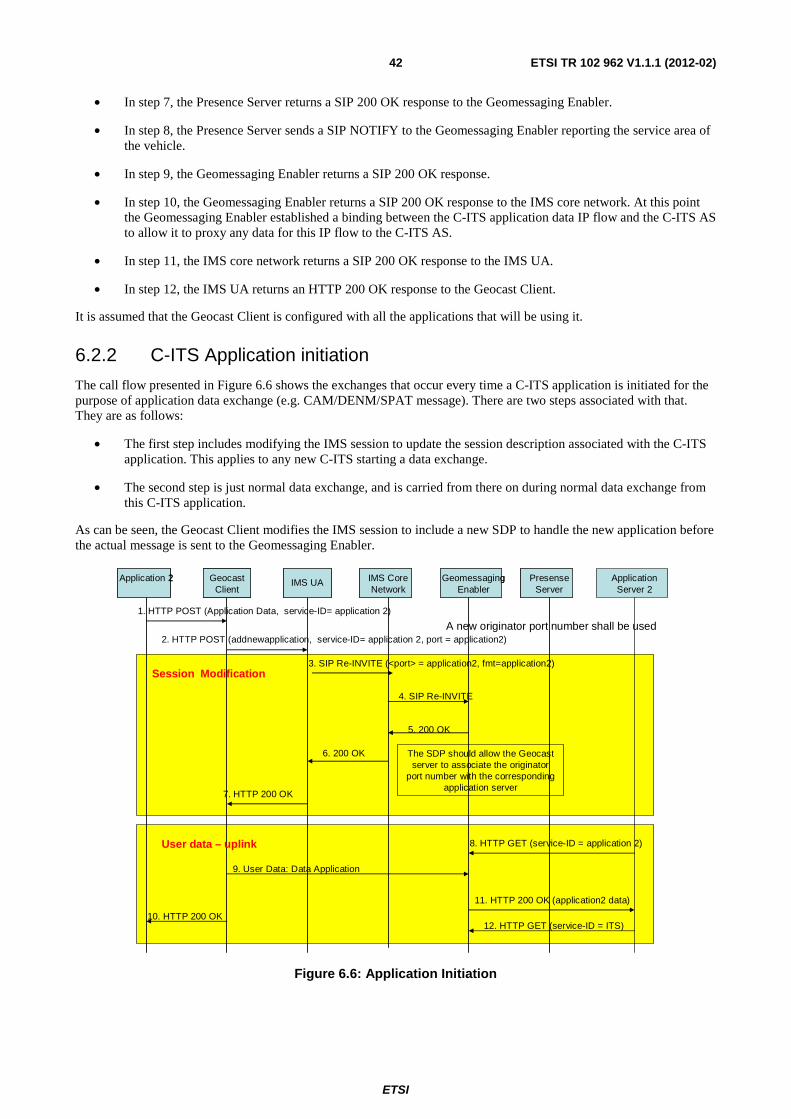
ETSI
ETSI TR 102 962 V1.1.1 (2012-02) 42
• In step 7, the Presence Server returns a SIP 200 OK response to the Geomessaging Enabler.
• In step 8, the Presence Server sends a SIP NOTIFY to the Geomessaging Enabler reporting the service area of the vehicle.
• In step 9, the Geomessaging Enabler returns a SIP 200 OK response.
• In step 10, the Geomessaging Enabler returns a SIP 200 OK response to the IMS core network. At this point the Geomessaging Enabler established a binding between the C-ITS application data IP flow and the C-ITS AS to allow it to proxy any data for this IP flow to the C-ITS AS.
• In step 11, the IMS core network returns a SIP 200 OK response to the IMS UA.
• In step 12, the IMS UA returns an HTTP 200 OK response to the Geocast Client.
It is assumed that the Geocast Client is configured with all the applications that will be using it.
6.2.2 C-ITS Application initiation
The call flow presented in Figure 6.6 shows the exchanges that occur every time a C-ITS application is initiated for the purpose of application data exchange (e.g. CAM/DENM/SPAT message). There are two steps associated with that. They are as follows:
• The first step includes modifying the IMS session to update the session description associated with the C-ITS application. This applies to any new C-ITS starting a data exchange.
• The second step is just normal data exchange, and is carried from there on during normal data exchange from this C-ITS application.
As can be seen, the Geocast Client modifies the IMS session to include a new SDP to handle the new application before the actual message is sent to the Geomessaging Enabler.
Session Modification
PresenseServer
PresenseServer
Application Server 2
IMS UAIMS UA IMS Core Network
IMS Core Network
GeoClientGeocastClient
GeoClientGeocastClient
Application 2Application 2
7. HTTP 200 OK
4. SIP Re-INVITE
5. 200 OK
6. 200 OK
1. HTTP POST (Application Data, service-ID= application 2)
2. HTTP POST (addnewapplication, service-ID= application 2, port = application2)
11. HTTP 200 OK (application2 data)
9. User Data: Data Application
10. HTTP 200 OK
8. HTTP GET (service-ID = application 2)
12. HTTP GET (service-ID = ITS)
The SDP should allow the Geocastserver to associate the originator
port number with the corresponding application server
A new originator port number shall be used
3. SIP Re-INVITE (<port> = application2, fmt=application2)
User data – uplink
GeomessagingEnabler
GeomessagingEnabler
Figure 6.6: Application Initiation
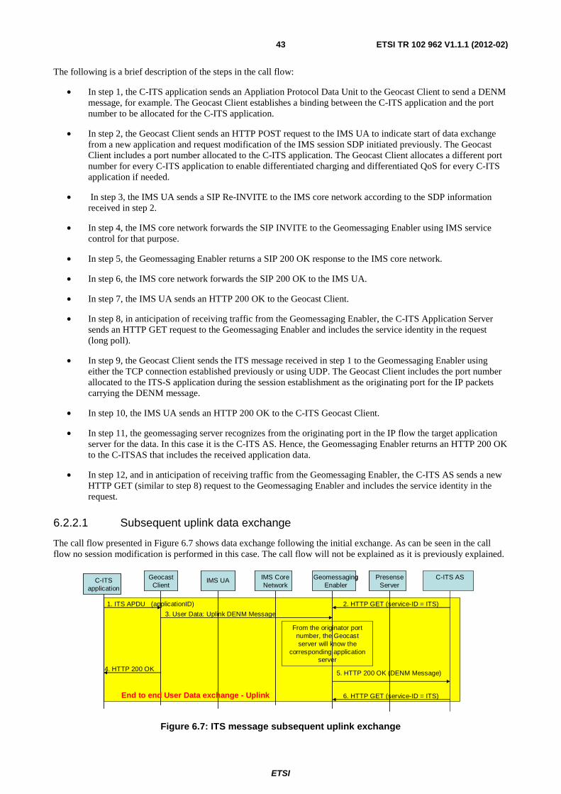
ETSI
ETSI TR 102 962 V1.1.1 (2012-02) 43
The following is a brief description of the steps in the call flow:
• In step 1, the C-ITS application sends an Appliation Protocol Data Unit to the Geocast Client to send a DENM message, for example. The Geocast Client establishes a binding between the C-ITS application and the port number to be allocated for the C-ITS application.
• In step 2, the Geocast Client sends an HTTP POST request to the IMS UA to indicate start of data exchange from a new application and request modification of the IMS session SDP initiated previously. The Geocast Client includes a port number allocated to the C-ITS application. The Geocast Client allocates a different port number for every C-ITS application to enable differentiated charging and differentiated QoS for every C-ITS application if needed.
• In step 3, the IMS UA sends a SIP Re-INVITE to the IMS core network according to the SDP information received in step 2.
• In step 4, the IMS core network forwards the SIP INVITE to the Geomessaging Enabler using IMS service control for that purpose.
• In step 5, the Geomessaging Enabler returns a SIP 200 OK response to the IMS core network.
• In step 6, the IMS core network forwards the SIP 200 OK to the IMS UA.
• In step 7, the IMS UA sends an HTTP 200 OK to the Geocast Client.
• In step 8, in anticipation of receiving traffic from the Geomessaging Enabler, the C-ITS Application Server sends an HTTP GET request to the Geomessaging Enabler and includes the service identity in the request (long poll).
• In step 9, the Geocast Client sends the ITS message received in step 1 to the Geomessaging Enabler using either the TCP connection established previously or using UDP. The Geocast Client includes the port number allocated to the ITS-S application during the session establishment as the originating port for the IP packets carrying the DENM message.
• In step 10, the IMS UA sends an HTTP 200 OK to the C-ITS Geocast Client.
• In step 11, the geomessaging server recognizes from the originating port in the IP flow the target application server for the data. In this case it is the C-ITS AS. Hence, the Geomessaging Enabler returns an HTTP 200 OK to the C-ITSAS that includes the received application data.
• In step 12, and in anticipation of receiving traffic from the Geomessaging Enabler, the C-ITS AS sends a new HTTP GET (similar to step 8) request to the Geomessaging Enabler and includes the service identity in the request.
6.2.2.1 Subsequent uplink data exchange
The call flow presented in Figure 6.7 shows data exchange following the initial exchange. As can be seen in the call flow no session modification is performed in this case. The call flow will not be explained as it is previously explained.
PresenseServer
PresenseServer
C-ITS ASIMS UAIMS UA IMS Core Network
IMS Core Network
GeoClientGeocastClient
GeoClientGeocastClient
C-ITS application
C-ITS application
5. HTTP 200 OK (DENM Message)
3. User Data: Uplink DENM Message
4. HTTP 200 OK
2. HTTP GET (service-ID = ITS)
6. HTTP GET (service-ID = ITS)
From the originator port number, the Geocastserver will know the
corresponding application server
End to end User Data exchange - Uplink
GeomessagingEnabler
GeomessagingEnabler
1. ITS APDU (applicationID)
Figure 6.7: ITS message subsequent uplink exchange
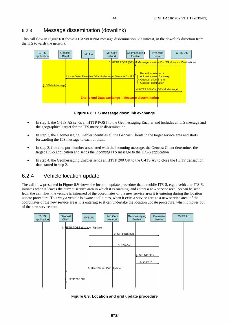
ETSI
ETSI TR 102 962 V1.1.1 (2012-02) 44
6.2.3 Message dissemination (downlink)
This call flow in Figure 6.8 shows a CAM/DENM message dissemination, via unicast, in the downlink direction from the ITS towards the network.
End to end Data exchange – Message dissemination
PresenseServer
PresenseServer
C-ITS ASIMS UAIMS UA IMS Core Network
IMS Core Network
GeoClientGeocastClient
GeoClientGeocastClient
C-ITS application
C-ITS application
4. HTTP 200 OK (DENM Message)
2. User Data: Downlink DENM Message, Service-ID= ITS
1. HTTP POST (DENM Message, service-ID= ITS, Geocast Destination)
3. DENM Message)
Repeat as needed if unicast is used for every Geocast client in the Geocast destination
GeomessagingEnabler
GeomessagingEnabler
Figure 6.8: ITS message downlink exchange
• In step 1, the C-ITS AS sends an HTTP POST to the Geomessaging Enabler and includes an ITS message and the geographical target for the ITS message dissemination.
• In step 2, the Geomessaging Enabler identifies all the Geocast Clients in the target service area and starts forwarding the ITS message to each of them.
• In step 3, from the port number associated with the incoming message, the Geocast Client determines the target ITS-S application and sends the incoming ITS message to the ITS-S application.
• In step 4, the Geomessaging Enabler sends an HTTP 200 OK to the C-ITS AS to close the HTTP transaction that started in step 2.
6.2.4 Vehicle location update
The call flow presented in Figure 6.9 shows the location update procedure that a mobile ITS-S, e.g. a vehicular ITS-S, initiates when it leaves the current service area in which it is roaming, and enters a new service area. As can be seen from the call flow, the vehicle is informed of the coordinates of the new service area it is entering during the location update procedure. This way a vehicle is aware at all times, when it exits a service area to a new service area, of the coordinates of the new service areas it is entering so it can undertake the location update procedure, when it moves out of the new service area.
PresenseServer
PresenseServer
C-ITS ASIMS UAIMS UA IMS Core Network
IMS Core Network
GeoClientGeocastClient
GeoClientGeocastClient
C-ITS application
C-ITS application
1. HTTP POST (Location Update )
2. SIP PUBLISH
7. HTTP 200 OK
4. SIP NOTIFY
5. 200 OK
3. 200 OK
6. User Plane: Grid Update
GeomessagingEnabler
GeomessagingEnabler
Figure 6.9: Location and grid update procedure
ETSI
ETSI TR 102 962 V1.1.1 (2012-02) 45
The following is a brief description of the steps in the call flow:
• In step 1, the Geocast Client is aware that it is exiting a service area and entering a new service area. It sends an HTTP POST request to inform the IMS UA of the event.
• In step2, the IMS UA sends a SIP PUBLISH to the presence server via the IMS core network.
• In step 3, the presence server returns a SIP 200 OK response to the IMS UA.
• In step 4, the presence server sends a SIP NPOTIFY to the Geomessaging Enabler to inform it of the new service area for the (vehicular) ITS-S.
• In step 5, the Geomessaging Enabler returns a SIP 200 OK response to the presence server.
• In step 6, the Geomessaging Enabler sends a user data message to the Geocast Client to inform it of the coordinates of the new service area that it is entering.
• In step 7, the IMS UA sends an HTTP 200 OK to the Geocast Client.
6.3 Mapping the Geomessaging Enabler to C-ITS architecture Figure 6.10 shows the locations of the Geomessaging Enabler and Geocast Client within the C-ITS architecture.
Cellular Network including
IMS Core Network/Service Network
Networking & Transport
Ma
nag
emen
tM
ana
gem
ent
ec
Facilities
Applications
IN
NF
FA
MS
MI
MN
MF
Access
Secu
rity
SI
SFSFS
NS
N
Geo Client
Networking & Transport
Ma
nag
emen
t
ec
Facilities
Applications
IN
NF
FA
MS
MI
MN
MF
Access
Secu
rity
SI
SF
SN
Geo Client
Networking & Transport
Ma
nag
emen
tM
ana
gem
ent
ec
Facilities
Applications
IN
NF
FA
MS
MI
MN
MF
Access
Secu
rity
SI
SF
SF
SNSN
Geo Client
Networking & Transport
Man
ag
eme
nt
ecITS-AS
IN
NF
FA
MS
MI
MN
MF
Access
Sec
uri
ty
SI
SF
SN
Facilities
Networking & Transport
Man
ag
eme
nt
Man
ag
eme
nt
ecITS-AS
IN
NF
FA
MS
MI
MN
MF
Access
Sec
uri
ty
SI
SF
SF
SN
SN
Facilities
Networking & Transport
Man
ag
eme
nt
Man
ag
eme
nt
ec
Geomessaging
IN
NF
FA
MS
MI
MN
MF
Access
Sec
uri
ty
SI
SF
SF
SN
SN
GC-SAPGC-SAP
GC-SAPGC-SAP
Figure 6.10: Geomessaging enabler and the C-ITS architecture (Gateway deployment option)
From Figure 6.10 the following can be noted:
• The Geocast Client resides in the ITS-S facilities layer. It has a SAP, labeled GC-SAP and can be accessed directly by all applications in the application layer as well as applications at the facilities layer.
• The Geomessaging Enabler is assumed to be an ITS-S facilities layer application residing either in a gateway of a central ITS station (Figure 6.10) or co-located within the central-ITS station itself (Figure 6.11).
The ITS AS is assumed to be an ITS-S application residing in a central ITS-S. It communicates with the Geomessaging Enabler using HTTP. An ITS-AS may communicate with other ITS-S applications residing in the ITS-S.
ETSI
ETSI TR 102 962 V1.1.1 (2012-02) 46
Cellular Network including
IMS Core Network/Service Network
Networking & Transport
Ma n
agem
ent
Ma n
agem
ent
ec
Facilities
Applications
IN
NF
FA
MS
MI
MN
MF
Access
Secu
rity
SI
SFSFSNSN
Geo Client
Networking & Transport
Ma
nag
emen
t
ec
Facilities
Applications
IN
NF
FA
MS
MI
MN
MF
Access
Secu
rity
SI
SFSN
Geo Client
GC-SAP
Networking & Transport
Ma
nag
emen
tM
ana
gem
ent
ec
Facilities
Applications
IN
NF
FA
MS
MI
MN
MF
Access
Secu
rity
SI
SFSFSNSN
Geo Client
GC-SAPGC-SAP
Networking &
Transport
Ma
na
ge
me
nt
Ma
na
ge
me
nt
ec
Applications
IN
NF
FA
MS
MI
MN
MF
Access
Sec
uri
ty
SI
SF
SF
SN
SN
Geomessaging
Facilities
GC-SAPGC-SAP
ITS-AS
Figure 6.11: Geomessaging enabler and the C-ITS architecture (Central deployment Option)
6.3.1 Scalability and handling of multiple Geomessaging Enablers
Within a typical cellular network, it is expected that multiple Geomessaging Enablers should provide service in support of C-ITS. The IMS core network ensure the allocation of Geocast clients to Geomessaging Enablers, is carried in a fashion that ensures proper load distribution.
Each instance of a Geomessaging Enabler is connected to favorably a single central C-ITS AS per region. For message dissemination, the C-ITS AS sends the message to all Geomessaging Enablers connected to it. Each of these enablers in turn sends the information to the appropriate Geocast Clients they handle.
Figure 6.12 illustrates the above concept.
ETSI
ETSI TR 102 962 V1.1.1 (2012-02) 47
Cellular Network including
IMS Core Network/Service Network
Networking & Transport
Ma
nag
emen
tM
ana
gem
ent
ec
Facilities
Applications
IN
NF
FA
MS
MI
MN
MF
Access
Secu
rity
SI
SFSFSNSN
Geo Client
Networking & Transport
Ma
nag
emen
t
ec
Facilities
Applications
IN
NF
FA
MS
MI
MN
MF
Access
Secu
rity
SI
SF
SN
Geo Client
Networking & Transport
Ma
nag
emen
tM
ana
gem
ent
ec
Facilities
Applications
IN
NF
FA
MS
MI
MN
MF
Access
Secu
rity
SI
SF
SF
SNSN
Geo Client
Networking & Transport
Man
ag
eme
nt
ec
ITS-AS
IN
NF
FA
MS
MI
MN
MF
Access
Sec
uri
ty
SI
SF
SN
Facilities
Networking & Transport
Man
ag
eme
nt
Man
ag
eme
nt
ec
ITS-AS
IN
NF
FA
MS
MI
MN
MF
Access
Sec
uri
ty
SI
SF
SF
SN
SN
Facilities
Networking & Transport
Man
ag
eme
nt
ec
Geomessaging
IN
NF
FA
MS
MI
MN
MF
Access
Sec
uri
ty
SI
SF
SNNetworking &
Transport
Man
ag
eme
nt
Man
ag
eme
nt
ec
Geomessaging
IN
NF
FA
MS
MI
MN
MF
Access
Sec
uri
ty
SI
SF
SF
SN
SN
GC-SAPGC-SAP
GC-SAPGC-SAP
Networking & Transport
Ma
na
ge
me
nt
ec
Geomessaging
IN
NF
FA
MS
MI
MN
MF
Access
Sec
uri
ty
SI
SF
SNNetworking &
Transport
Ma
na
ge
me
nt
Ma
na
ge
me
nt
ec
Geomessaging
IN
NF
FA
MS
MI
MN
MF
Access
Sec
uri
ty
SI
SF
SF
SN
SN
Cellular Network including
IMS Core Network/Service Network
Cellular Network including
IMS Core Network/Service Network
Networking & Transport
Ma
na
ge
me
nt
ec
Geomessaging
IN
NF
FA
MS
MI
MN
MF
Access
Sec
uri
ty
SI
SF
SNNetworking &
Transport
Ma
na
ge
me
nt
Ma
na
ge
me
nt
ec
Geomessaging
IN
NF
FA
MS
MI
MN
MF
Access
Sec
uri
ty
SI
SF
SF
SN
SNNetworking &
Transport
Ma
na
ge
me
nt
ec
Geomessaging
IN
NF
FA
MS
MI
MN
MF
Access
Sec
uri
ty
SI
SF
SNNetworking &
Transport
Ma
na
ge
me
nt
Ma
na
ge
me
nt
ec
Geomessaging
IN
NF
FA
MS
MI
MN
MF
Access
Sec
uri
ty
SI
SF
SF
SN
SNNetworking &
Transport
Ma
na
ge
me
nt
ec
Geomessaging
IN
NF
FA
MS
MI
MN
MF
Access
Sec
uri
ty
SI
SF
SNNetworking &
Transport
Ma
na
ge
me
nt
Ma
na
ge
me
nt
ec
Geomessaging
IN
NF
FA
MS
MI
MN
MF
Access
Sec
uri
ty
SI
SF
SF
SN
SNNetworking &
Transport
Ma
na
ge
me
nt
ec
Geomessaging
IN
NF
FA
MS
MI
MN
MF
Access
Sec
uri
ty
SI
SF
SNNetworking &
Transport
Ma
na
ge
me
nt
Ma
na
ge
me
nt
ec
Geomessaging
IN
NF
FA
MS
MI
MN
MF
Access
Sec
uri
ty
SI
SF
SF
SN
SNNetworking &
Transport
Ma
na
ge
me
nt
ec
Geomessaging
IN
NF
FA
MS
MI
MN
MF
Access
Sec
uri
ty
SI
SF
SNNetworking &
Transport
Ma
na
ge
me
nt
Ma
na
ge
me
nt
ec
Geomessaging
IN
NF
FA
MS
MI
MN
MF
Access
Sec
uri
ty
SI
SF
SF
SN
SN
Figure 6.12: Geomessaging Scalability
6.3.2 Handling of multiple cellular networks
In a typical situation Geocast Clients in any area are served by multiple cellular providers. To ensure that all Geocast Clients in any area covered by multiple service providers receive the proper information, the ITS-S including the C-ITS AS should be connected to Geomessaging Enablers for all cellular service providers.
7 Identification and enhancements of ITS applications and related use cases
7.1 Introduction Clause 6 identified capabilities of cellular networks that can be used for providing C-ITS services. The use cases identified in [i.16] (BSA) have been analysed considering these capabilities with the goal of identifying the ones that can be deployed I in cellular networks, as well as the additional capabilities that have to be supported by these use cases for that matter.
It is important to note that this analysis has been done with the intention of highlighting what needs to be considered in the specification of C-ITS applications and use cases in order to be agnostic to the communication protocol stack, and hence enabling multiple access technologies other than just ITS-G5. The objective is to define a framework that allows identified use cases to use cellular networks as an access technology, in addition to other communication alternatives.
Depending on the use case, and the actual topological environment regarding the location of an ITS-S unit, and according to use case parameters, the following options are possible:
• circumstances where a single access technology (communication profile) is selected, and
• circumstances where there is a choice between several communication profiles, and
ETSI
ETSI TR 102 962 V1.1.1 (2012-02) 48
• circumstances where more than one communication profile will be used simultaneously.
NOTE: Source and rationale of requirements like latency, repetition time in [i.16] (BSA) are unknown and need further study.
One of the main outcomes of this study is that cellular network local broadcasting features need to be added on top of the deployed unicast features of the commercial cellular networks. This allows the network to elaborate the information and to broadcast it to all ITS-S units in a defined area, referred to, as "relevance area" in [i.15].
As indicate above, an essential new network feature is identified to in clause 5 and referred to as "Geomessaging Enabler". The "Geomessaging Enabler" provides the capability of the network to broadcast information to all ITS-S units in a relevance area, which may rely on a "Geocast Enabler" and/or on broadcasting capabilities such as MBMS and PWS.
7.2 Use case support
7.2.1 Introduction
In BSA [i.16] requirements for CAM and DENM are essentially conceived and specified with the assumption of the G5 communication profile and a decentralised architecture. These assumptions tainted the requirements and the use cases breaking the well-grounded architecture principle of "separation of concerns". This principle requires that use cases be exclusively specified in a way reflective of their desired functionality irrespective of any communication profile. Furthermore, this principle requires that identified use cases should be based on the needs of a system and not a communication profile.
The subclauses below discusses the ways in which cellular networks can support existing use cases and the impact that cellular network communication profile may have on these use cases.
7.2.2 DENM
DENM is related to event detection and dissemination. Support of DENM by cellular networks can bring the added value in the ability to consolidate the numerous events that are originated from all the vehicles in the various relevance areas, coordinating these events, and tracking them in a way that allows only dissemination of useful information in a specific relevance area. This added intelligence for data miming can only be centrally supported.
Without any consideration to the business value associated with the consolidation and coordination of events related information, this has several advantages:
1) Uplink notification of the event can be easily filtered by the originating vehicle based on the acknowledged notification of the same event in the downlink channel. This eliminates the need to repeat sending the same event again. This promotes system scalability and congestion avoidance.
2) Policies can be built in the geomessaging, enabler, discussed above in clause 6, that allow information related to events to be disseminated to an area larger than the original relevance area if warranted. The vehicle can enter the alarm area already pre-warned and increasing warning levels can be assigned when nearing the area with the source of the event.
3) For an approaching vehicle, there is no need of having a vehicle in its vicinities to be notified of any event. The dissemination of the event is guaranteed by the cellular wide coverage.
7.2.3 CAM
CAM is relevant to beaconing vehicle positions and finds its main application in car crash avoidance applications or in assistance applications that are active only when two vehicles are close to each other.
Relaying a beaconing position message on the radio access is a clear disadvantage for cellular networks in terms of expected latency of the message, as well as the potential congestion this can bring about to the network itself. Clause 5 indicates how easy it is to flood a cell if such a message is to be carried over a cellular network. On the other hand, cellular networks provide advantages in terms of coverage, where obstacles do not allow line of sight for all the vehicles in the intended traffic areas.
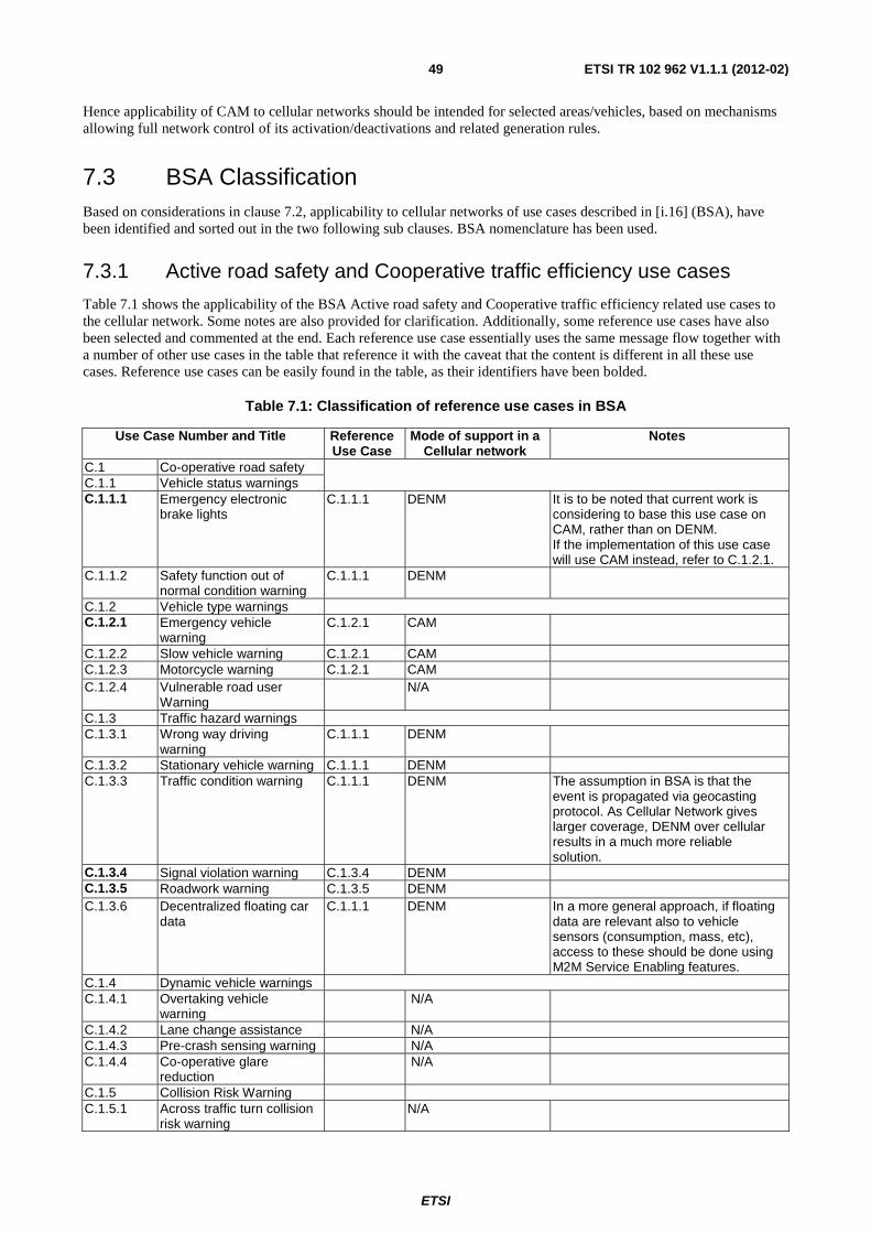
ETSI
ETSI TR 102 962 V1.1.1 (2012-02) 49
Hence applicability of CAM to cellular networks should be intended for selected areas/vehicles, based on mechanisms allowing full network control of its activation/deactivations and related generation rules.
7.3 BSA Classification Based on considerations in clause 7.2, applicability to cellular networks of use cases described in [i.16] (BSA), have been identified and sorted out in the two following sub clauses. BSA nomenclature has been used.
7.3.1 Active road safety and Cooperative traffic efficiency use cases
Table 7.1 shows the applicability of the BSA Active road safety and Cooperative traffic efficiency related use cases to the cellular network. Some notes are also provided for clarification. Additionally, some reference use cases have also been selected and commented at the end. Each reference use case essentially uses the same message flow together with a number of other use cases in the table that reference it with the caveat that the content is different in all these use cases. Reference use cases can be easily found in the table, as their identifiers have been bolded.
Table 7.1: Classification of reference use cases in BSA
Use Case Number and Title Reference Use Case
Mode of support in a Cellular network
Notes
C.1 Co-operative road safety C.1.1 Vehicle status warnings C.1.1.1 Emergency electronic
brake lights C.1.1.1 DENM It is to be noted that current work is
considering to base this use case on CAM, rather than on DENM. If the implementation of this use case will use CAM instead, refer to C.1.2.1.
C.1.1.2 Safety function out of normal condition warning
C.1.1.1 DENM
C.1.2 Vehicle type warnings C.1.2.1 Emergency vehicle
warning C.1.2.1 CAM
C.1.2.2 Slow vehicle warning C.1.2.1 CAM C.1.2.3 Motorcycle warning C.1.2.1 CAM C.1.2.4 Vulnerable road user
Warning N/A
C.1.3 Traffic hazard warnings C.1.3.1 Wrong way driving
warning C.1.1.1 DENM
C.1.3.2 Stationary vehicle warning C.1.1.1 DENM C.1.3.3 Traffic condition warning C.1.1.1 DENM The assumption in BSA is that the
event is propagated via geocasting protocol. As Cellular Network gives larger coverage, DENM over cellular results in a much more reliable solution.
C.1.3.4 Signal violation warning C.1.3.4 DENM C.1.3.5 Roadwork warning C.1.3.5 DENM C.1.3.6 Decentralized floating car
data C.1.1.1 DENM In a more general approach, if floating
data are relevant also to vehicle sensors (consumption, mass, etc), access to these should be done using M2M Service Enabling features.
C.1.4 Dynamic vehicle warnings C.1.4.1 Overtaking vehicle
warning N/A
C.1.4.2 Lane change assistance N/A C.1.4.3 Pre-crash sensing warning N/A C.1.4.4 Co-operative glare
reduction N/A
C.1.5 Collision Risk Warning C.1.5.1 Across traffic turn collision
risk warning N/A
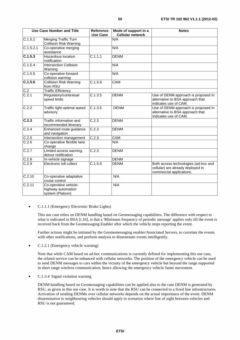
ETSI
ETSI TR 102 962 V1.1.1 (2012-02) 50
Use Case Number and Title Reference Use Case
Mode of support in a Cellular network
Notes
C.1.5.2 Merging Traffic Turn Collision Risk Warning
N/A
C.1.5.2.1 Co-operative merging assistance
N/A
C.1.5.3 Hazardous location notification
C.1.1.1 DENM
C.1.5.4 Intersection Collision Warning
N/A
C.1.5.5 Co-operative forward collision warning
N/A
C.1.5.6 Collision Risk Warning from RSU
C.1.5.6 CAM
C.2 Traffic Efficiency C.2.1 Regulatory/contextual
speed limits C.1.3.5 DENM Use of DENM approach is proposed In
alternative to BSA approach that indicates use of CAM.
C.2.2 Traffic light optimal speed advisory
C.1.3.5 DENM Use of DENM approach is proposed In alternative to BSA approach that indicates use of CAM.
C.2.3 Traffic information and recommended itinerary
C.2.3 DENM
C.2.4 Enhanced route guidance and navigation
C.2.3 DENM
C.2.5 Intersection management C.2.3 CAM C.2.6 Co-operative flexible lane
change N/A
C.2.7 Limited access warning, detour notification
C.2.3 DENM
C.2.8 In-vehicle signage DENM C.2.9 Electronic toll collect C.1.5.6 DENM Both access technologies (ad-hoc and
cellular) are already deployed in commercial applications.
C.2.10 Co-operative adaptative cruise control
N/A
C.2.11 Co-operative vehicle-highway automation system (Platoon)
N/A
• C.1.1.1 (Emergency Electronic Brake Lights)
This use case relies on DENM handling based on Geomessaging capabilities. The difference with respect to what is indicated in BSA [i.16], is that a 'Minimum frequency of periodic message' applies only till the event is received back from the Geomessaging Enabler after which the vehicle stops reporting the event.
Further actions might be initiated by the Geomemessaging enabler/Associated Servers, to correlate the events with other notifications, and perform analysis to disseminate events intelligently.
• C.1.2.1 (Emergency vehicle warning)
Note that while CAM based on ad-hoc communications is currently defined for implementing this use case, the related service can be enhanced with cellular networks. The position of the emergency vehicle can be used to send DENM messages to cars within the vicinity of the emergency vehicle but beyond the range supported in short range wireless communication, hence allowing the emergency vehicle faster movement.
• C.1.3.4 Signal violation warning
DENM handling based on Geomessaging capabilities can be applied also to the case DENM is generated by RSU, as given in this use case. It is worth to note that the RSU can be connected to a fixed line infrastructures. Activation of sending DENMs over cellular networks depends on the actual importance of the event. DENM dissemination to neighbouring vehicles should apply to scenarios where line of sight between vehicles and RSU is not guaranteed.
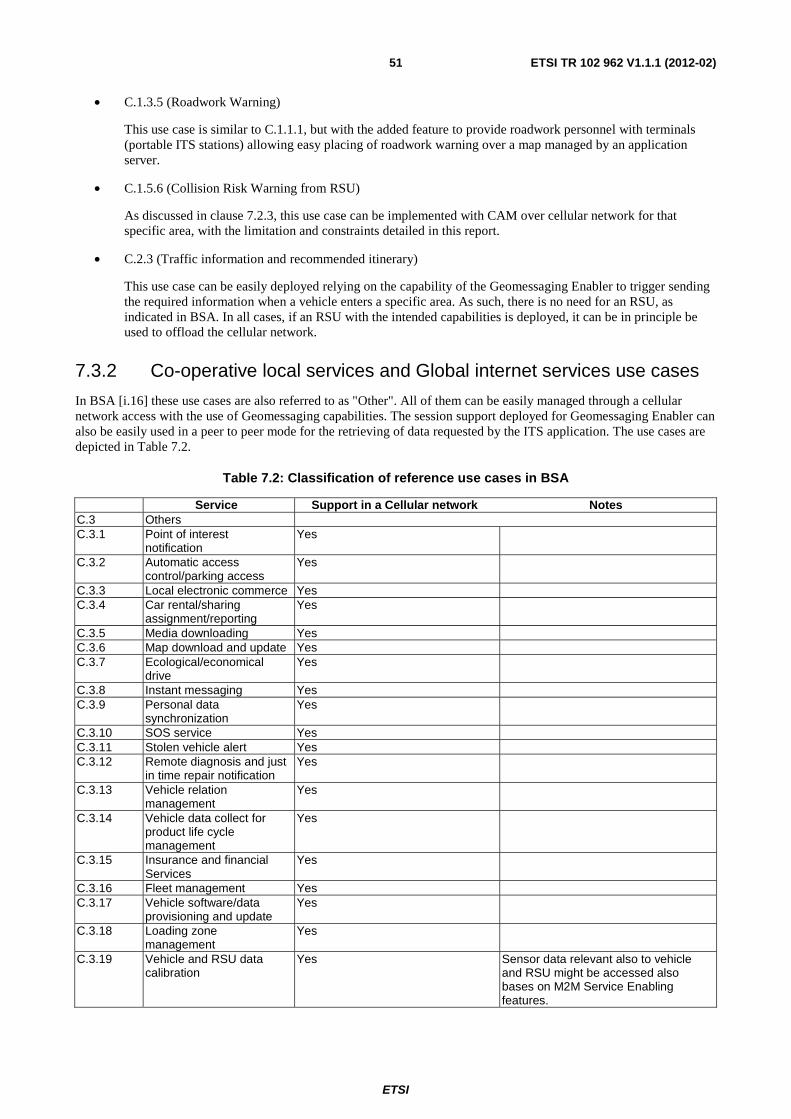
ETSI
ETSI TR 102 962 V1.1.1 (2012-02) 51
• C.1.3.5 (Roadwork Warning)
This use case is similar to C.1.1.1, but with the added feature to provide roadwork personnel with terminals (portable ITS stations) allowing easy placing of roadwork warning over a map managed by an application server.
• C.1.5.6 (Collision Risk Warning from RSU)
As discussed in clause 7.2.3, this use case can be implemented with CAM over cellular network for that specific area, with the limitation and constraints detailed in this report.
• C.2.3 (Traffic information and recommended itinerary)
This use case can be easily deployed relying on the capability of the Geomessaging Enabler to trigger sending the required information when a vehicle enters a specific area. As such, there is no need for an RSU, as indicated in BSA. In all cases, if an RSU with the intended capabilities is deployed, it can be in principle be used to offload the cellular network.
7.3.2 Co-operative local services and Global internet services use cases
In BSA [i.16] these use cases are also referred to as "Other". All of them can be easily managed through a cellular network access with the use of Geomessaging capabilities. The session support deployed for Geomessaging Enabler can also be easily used in a peer to peer mode for the retrieving of data requested by the ITS application. The use cases are depicted in Table 7.2.
Table 7.2: Classification of reference use cases in BSA
Service Support in a Cellular network Notes C.3 Others C.3.1 Point of interest
notification Yes
C.3.2 Automatic access control/parking access
Yes
C.3.3 Local electronic commerce Yes C.3.4 Car rental/sharing
assignment/reporting Yes
C.3.5 Media downloading Yes C.3.6 Map download and update Yes C.3.7 Ecological/economical
drive Yes
C.3.8 Instant messaging Yes C.3.9 Personal data
synchronization Yes
C.3.10 SOS service Yes C.3.11 Stolen vehicle alert Yes C.3.12 Remote diagnosis and just
in time repair notification Yes
C.3.13 Vehicle relation management
Yes
C.3.14 Vehicle data collect for product life cycle management
Yes
C.3.15 Insurance and financial Services
Yes
C.3.16 Fleet management Yes C.3.17 Vehicle software/data
provisioning and update Yes
C.3.18 Loading zone management
Yes
C.3.19 Vehicle and RSU data calibration
Yes Sensor data relevant also to vehicle and RSU might be accessed also bases on M2M Service Enabling features.
ETSI
ETSI TR 102 962 V1.1.1 (2012-02) 52
8 Impact on standards for cooperative ITS
8.1 Introduction to standardization for C-ITS Architectures, related protocols, and data elements for cooperative ITS (C-ITS) are standardized at various international, regional and national standards development organisations (SDOs). CEN TC278 WG16 and ISO TC204 WG18 work together jointly on C-ITS elements complementing the work being conducted at ISO TC204 WG16 and ETSI TC ITS. C-ITS standardization at CEN TC278 and ETSI TC ITS is conducted under the EC mandate M/453 [i.1] and [i.2]. Global harmonization of C-ITS standards is promoted by M/453 and the joint EU / U.S. approach [i.3]. Various liaison agreements between SDOs exist, e.g. [i.6]. An internationally harmonised approach is urgently requested by the European Commission and the U.S. DOT [i.7].
Similar developments, which might provide beneficial functionality for C-ITS, are given in ETSI TC M2M, with a focus on machine-to-machine communication. The approach at ETSI TC M2M has to be considered for the overall C-ITS architecture, and for the C-ITS station communication architecture.
An approach towards a "Global Cooperative ITS Architecture" being the basis of all C-ITS standardization and implementation contains different architectural aspects which are either already standardized, or in the process of being standardized, or are not considered for standardization so far. Such architectural aspects are the framework for development of standards for protocols and data elements in order to enable the presented C-ITS functionality for a multiplicity of implementation architectures.
Usage of cellular network technologies 2G and 3G is already considered in CALM ITS standards from ISO TC204 WG16 [i.36], [i.32], [i.33], [i.38] and [i.37] in a way, that the cellular networks are "used as provided", i.e. with no management relations between the ITS stations and the cellular networks' management, and without functionalities being specifically developed for C-ITS.
Usage of cellular network technologies for C-ITS, including selected road safety and traffic efficiency applications, is also considered by the US DOT [i.4] as a complementary technology to 5,9 GHz IEEE 802.11p [i.50] WAVE [i.44].
Using LTE for C-ITS recently was proposed by ETRI, with details related to the usage in a CALM-compliant ITS-S installation to be specified in [i.31].
Using LTE or other suited cellular network technologies for C-ITS as proposed in the present document requires amendments to existent C-ITS architecture standards, and extensions to cellular service network functionalities as depicted above.
The major focus of the present document is on the standardization work done at ETSI, primarily in TC ITS and secondarily in TC M2M. Following the joint response of CEN and ETSI to the EC mandate M/453 [i.1] and [i.2], complementary standardization work at CEN TC278 WG16 is also considered. In order to support the global approach towards C-ITS [i.3] standardization work at ISO TC204, especially in WG16 and WG18, is deemed to be important for the present document.
Annex A provides recommendations on standardization work to be undertaken in order to enable efficient usage of LTE for C-ITS.
8.2 C-ITS architectures
8.2.1 C-ITS overall architecture
The requirements on C-ITS overall architecture identified in the present document should be considered for the development of the C-ITS framework architecture on roles and responsibilities [i.30] and potential further architecture standards. Essential statements to be included in [i.30] are to indicate precisely:
• the functional requirements, and advantages (e.g. performance and reliability improvements) given by the provision of multiple access technologies for the same ITS application object [i.19], especially using cellular technologies in addition to ad-hoc technologies also for road safety and traffic efficiency application objects;
• need for dynamic selection of communication profiles dependent on operation needs set up by "date, time and place", of which the details may be standardized in [i.23], [i.29] and [i.38];
ETSI
ETSI TR 102 962 V1.1.1 (2012-02) 53
• roles and functionality of traffic management centres and of new dedicated cellular network facilities involved in message services, e.g. CAM and DENM services [i.14] and [i.15].
M2M as currently being standardised by ETSI TC M2M should also be taken into consideration to make sure that the ITS architectural concept becomes part of the larger "smart cities" framework where distributed sensors and M2M devices can be deployed to collect a broad variety of data and / or to monitor / control distributed cooperative processes. Transportation, mobility and road safety management are likely among those processes. At the moment, the interoperability among the M2M and ITS standards is not yet fully guaranteed, but it is expected that some synergy among ETSI TC M2M and TC ITS will be developed in order to increase the interoperability among the two system architectures and the related standards.
8.2.2 C-ITS communications architecture
The "ITS Communication Architecture" was standardized at ISO TC204 WG16 and later at ETSI TC ITS WG2, and was published in first versions by ETSI [i.18] and ISO [i.36]. IEEE TG 1609 started to develop an architecture standard for WAVE [i.44], which is limited to the usage of the 5,9 GHz ad-hoc access technology, aiming on partial harmonization with ETSI and ISO.
Although the approach illustrated in the ETSI ITS communications architecture [i.18] is very general, ETSI TC ITS so far allocated only work items in support of a small slice of C-ITS with very restricted technical features applicable for road safety and traffic efficiency [i.8], [i.9] and [i.10]. This approach is based on a communication profile given by:
• 5,9 GHz ad-hoc communications [i.17] and [i.35] in the ITS access layer,
• GeoNetworking protocols in the ITS networking & transport layer [i.12], [i.26] and [i.43] and
• functionality located in the facilities layer [i.21], [i.23], [i.24] and [i.42] are in support of the "Cooperative Awareness Service" [i.14] and the "Decentralized Environmental Notification Service" [i.15] and other services.
This communication profile so far is intended to be used by C-ITS applications identified in [i.16] with functional requirements specified in [i.13], see also the architectural specification [i.22].
The "Fast Service Advertisement Protocol" (FSAP) [i.42] specified at ISO as "cross-layer functionality" is being adopted by ETSI [i.21]. FSAP, as proven in the CVIS project, is suited to support cellular network technology for the session operation phase after initialisation is performed applying FSAP in an ad-hoc communication channel such as [i.17],[i.35] and [i.34]. Details on how to initiate operation of a specific cellular network service during the service initialization phase of FSAP need to be standardized.
ETSI TC ITS is aware of the whole "Basic set of CALM communication standards" developed at ISO TC204 WG16 which in principle may support any ITS-S application, any ITS-S facility layer functionality, any ITS-S networking & transport layer protocol, and any ITS-S access technology; all of this to be operated within a "Bounded Secured Managed Domain" (BSMD) [i.36] with dynamic set-up and maintenance of various communication profiles [i.38] and [i.29]. Following the liaison agreement between ETSI TC ITS and ISO TC204, set up by ETSI [i.6], ITS standards from ISO and ETSI are complementary standards.
8.3 C-ITS communications
8.3.1 Recognition of LTE in an ITS station
Recognition of LTE as an access technology for C-ITS is being specified in [i.31]. Requirements identified in the present document can be processed by ISO TC204 WG16. An active contribution from ETSI experts to the work conducted at ISO would be beneficial.
A new ETSI standard on LTE-related protocols might be referenced in [i.31] in order to ensure international harmonization.
Alternatively, mandatory references from ETSI standards to [i.31] would also be appropriate.
ETSI
ETSI TR 102 962 V1.1.1 (2012-02) 54
8.3.2 ITS station management
The general ITS station management specified by ISO in [i.38], [i.40] and [i.41] is a reasonable approach to support the requirements identified in the present document. Missing functionality should be added there. The first opportunity to do so is the actual revision work which will finish in 2012.
The new work item on remote ITS station management at ISO [i.39] should be used to implement related functionality for LTE.
ETSI TC ITS so far is not actively working on the new work [i.20] and so far has no work item on ITS station management. The management functionality required for ETSI protocols can be achieved by references to the related ISO standards.
8.3.3 Communication profile selection
Communication profile selection is an ITS-S management procedure applicable for all kinds of communications, e.g. information dissemination and application sessions, which can be done by static settings or dynamically dependent on actual needs. Static selection is included as a "simple option" in the automatic dynamic procedure specified in [i.38]. This automatic procedure is the recommended one in order to achieve optimum performance.
Details on the selection process, i.e. identification of selection criteria, are within the scope of the new work item [i.29] at CEN. Requirements identified in the present document should be considered there.
8.4 C-ITS applications C-ITS applications which so far are developed for usage with ad-hoc access technologies only [i.8], [i.9], [i.10] and [i.11], may beneficially use cellular networks for communications; details need to be identified. Distinction is made between C-ITS applications which can be served:
• only by cellular networks, or
• either by ad-hoc access technologies or by cellular networks, dependent on the actual situation.
Based on a top-down approach with the following three steps:
1) identification of use cases / ITS-S applications,
2) identification of functional requirements for communications per use case / ITS-S application,
3) identification of technical requirements for communications, including options, per use case / ITS-S application.
Modifications of reports and standards already developed at ETSI TC ITS WG1 are necessary.
Harmonization with US DOT views [i.4] is preferable and in line with the EU/US joint approach [i.3].
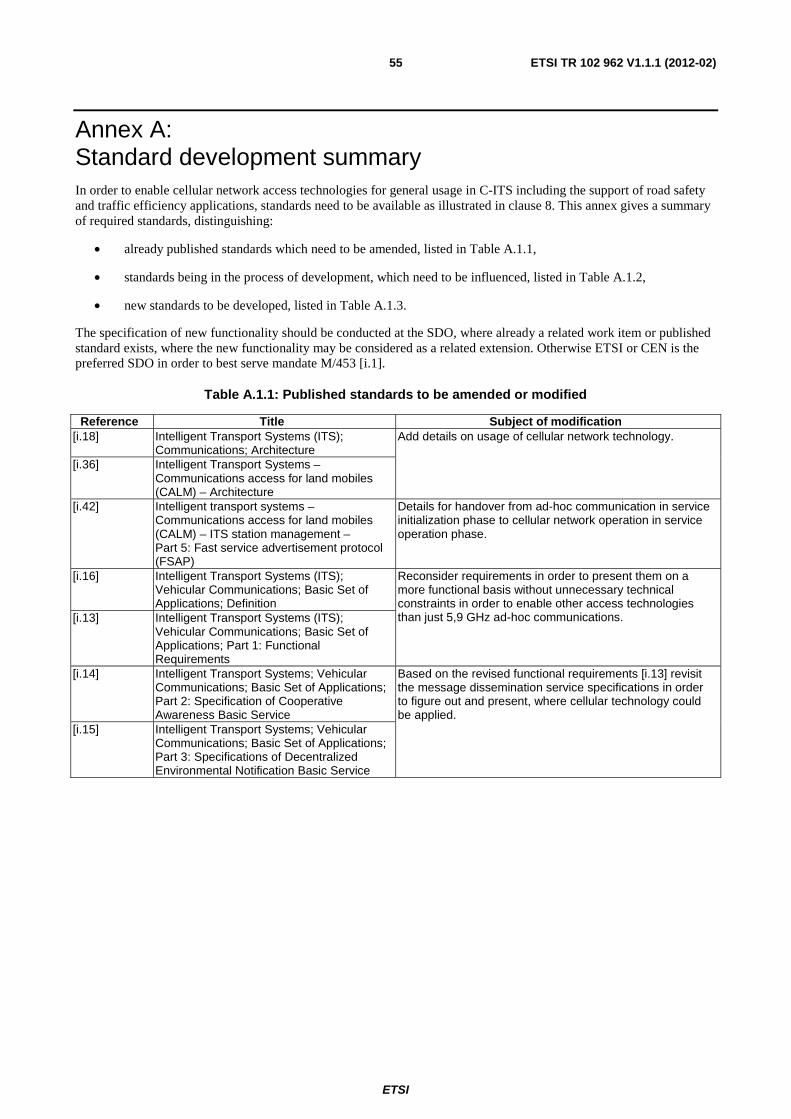
ETSI
ETSI TR 102 962 V1.1.1 (2012-02) 55
Annex A: Standard development summary In order to enable cellular network access technologies for general usage in C-ITS including the support of road safety and traffic efficiency applications, standards need to be available as illustrated in clause 8. This annex gives a summary of required standards, distinguishing:
• already published standards which need to be amended, listed in Table A.1.1,
• standards being in the process of development, which need to be influenced, listed in Table A.1.2,
• new standards to be developed, listed in Table A.1.3.
The specification of new functionality should be conducted at the SDO, where already a related work item or published standard exists, where the new functionality may be considered as a related extension. Otherwise ETSI or CEN is the preferred SDO in order to best serve mandate M/453 [i.1].
Table A.1.1: Published standards to be amended or modified
Reference Title Subject of modification [i.18] Intelligent Transport Systems (ITS);
Communications; Architecture Add details on usage of cellular network technology.
[i.36] Intelligent Transport Systems – Communications access for land mobiles (CALM) – Architecture
[i.42] Intelligent transport systems – Communications access for land mobiles (CALM) – ITS station management – Part 5: Fast service advertisement protocol (FSAP)
Details for handover from ad-hoc communication in service initialization phase to cellular network operation in service operation phase.
[i.16] Intelligent Transport Systems (ITS); Vehicular Communications; Basic Set of Applications; Definition
Reconsider requirements in order to present them on a more functional basis without unnecessary technical constraints in order to enable other access technologies than just 5,9 GHz ad-hoc communications. [i.13] Intelligent Transport Systems (ITS);
Vehicular Communications; Basic Set of Applications; Part 1: Functional Requirements
[i.14] Intelligent Transport Systems; Vehicular Communications; Basic Set of Applications; Part 2: Specification of Cooperative Awareness Basic Service
Based on the revised functional requirements [i.13] revisit the message dissemination service specifications in order to figure out and present, where cellular technology could be applied.
[i.15] Intelligent Transport Systems; Vehicular Communications; Basic Set of Applications; Part 3: Specifications of Decentralized Environmental Notification Basic Service
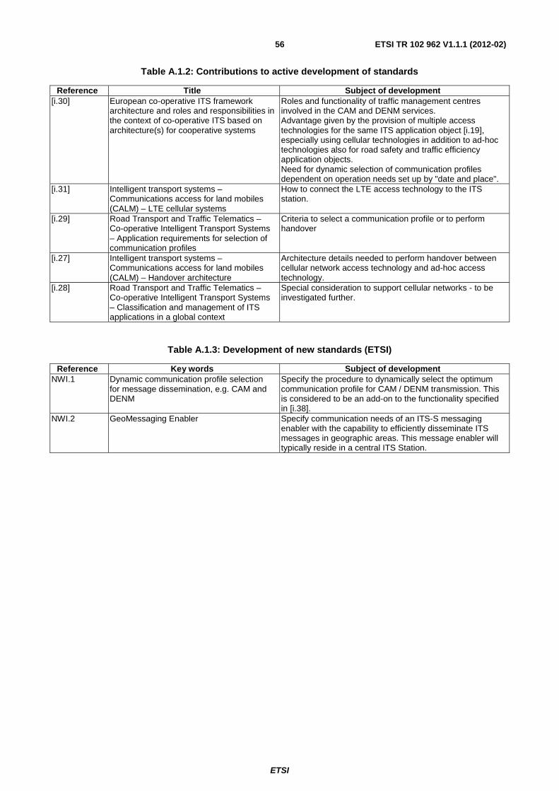
ETSI
ETSI TR 102 962 V1.1.1 (2012-02) 56
Table A.1.2: Contributions to active development of standards
Reference Title Subject of development [i.30] European co-operative ITS framework
architecture and roles and responsibilities in the context of co-operative ITS based on architecture(s) for cooperative systems
Roles and functionality of traffic management centres involved in the CAM and DENM services. Advantage given by the provision of multiple access technologies for the same ITS application object [i.19], especially using cellular technologies in addition to ad-hoc technologies also for road safety and traffic efficiency application objects. Need for dynamic selection of communication profiles dependent on operation needs set up by "date and place".
[i.31] Intelligent transport systems – Communications access for land mobiles (CALM) – LTE cellular systems
How to connect the LTE access technology to the ITS station.
[i.29] Road Transport and Traffic Telematics – Co-operative Intelligent Transport Systems – Application requirements for selection of communication profiles
Criteria to select a communication profile or to perform handover
[i.27] Intelligent transport systems – Communications access for land mobiles (CALM) – Handover architecture
Architecture details needed to perform handover between cellular network access technology and ad-hoc access technology.
[i.28] Road Transport and Traffic Telematics – Co-operative Intelligent Transport Systems – Classification and management of ITS applications in a global context
Special consideration to support cellular networks - to be investigated further.
Table A.1.3: Development of new standards (ETSI)
Reference Key words Subject of development NWI.1 Dynamic communication profile selection
for message dissemination, e.g. CAM and DENM
Specify the procedure to dynamically select the optimum communication profile for CAM / DENM transmission. This is considered to be an add-on to the functionality specified in [i.38].
NWI.2 GeoMessaging Enabler Specify communication needs of an ITS-S messaging enabler with the capability to efficiently disseminate ITS messages in geographic areas. This message enabler will typically reside in a central ITS Station.
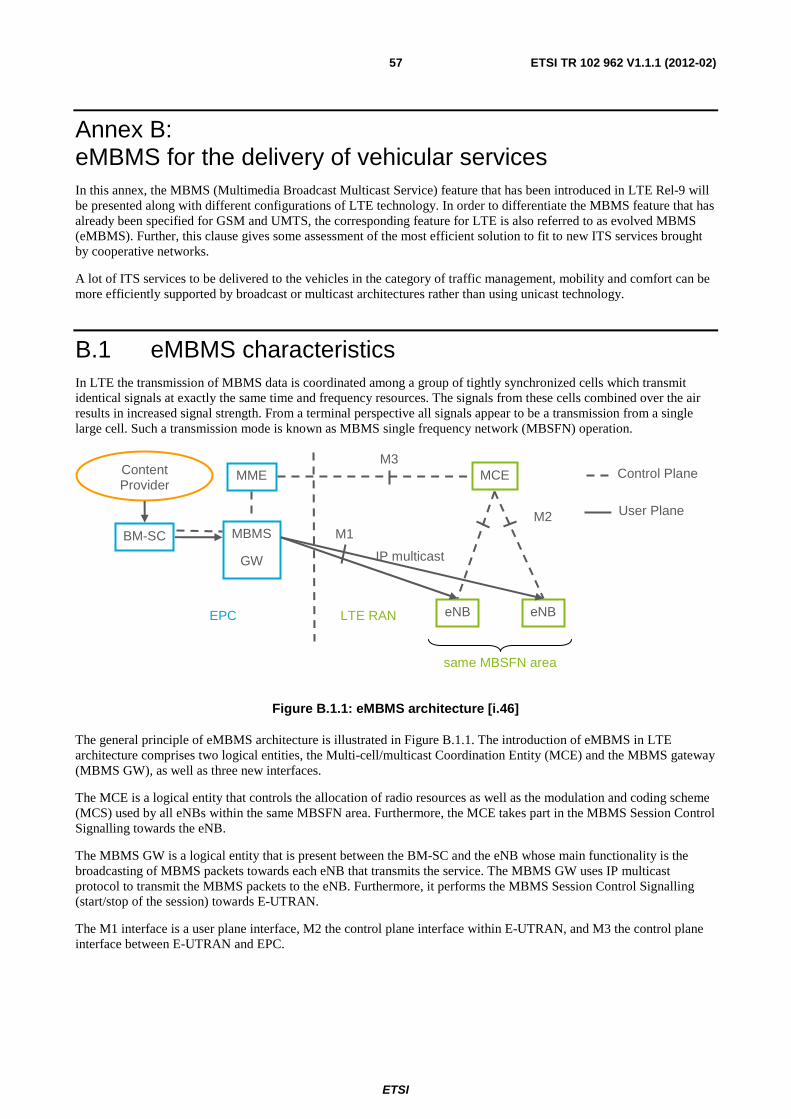
ETSI
ETSI TR 102 962 V1.1.1 (2012-02) 57
Annex B: eMBMS for the delivery of vehicular services In this annex, the MBMS (Multimedia Broadcast Multicast Service) feature that has been introduced in LTE Rel-9 will be presented along with different configurations of LTE technology. In order to differentiate the MBMS feature that has already been specified for GSM and UMTS, the corresponding feature for LTE is also referred to as evolved MBMS (eMBMS). Further, this clause gives some assessment of the most efficient solution to fit to new ITS services brought by cooperative networks.
A lot of ITS services to be delivered to the vehicles in the category of traffic management, mobility and comfort can be more efficiently supported by broadcast or multicast architectures rather than using unicast technology.
B.1 eMBMS characteristics In LTE the transmission of MBMS data is coordinated among a group of tightly synchronized cells which transmit identical signals at exactly the same time and frequency resources. The signals from these cells combined over the air results in increased signal strength. From a terminal perspective all signals appear to be a transmission from a single large cell. Such a transmission mode is known as MBMS single frequency network (MBSFN) operation.
Figure B.1.1: eMBMS architecture [i.46]
The general principle of eMBMS architecture is illustrated in Figure B.1.1. The introduction of eMBMS in LTE architecture comprises two logical entities, the Multi-cell/multicast Coordination Entity (MCE) and the MBMS gateway (MBMS GW), as well as three new interfaces.
The MCE is a logical entity that controls the allocation of radio resources as well as the modulation and coding scheme (MCS) used by all eNBs within the same MBSFN area. Furthermore, the MCE takes part in the MBMS Session Control Signalling towards the eNB.
The MBMS GW is a logical entity that is present between the BM-SC and the eNB whose main functionality is the broadcasting of MBMS packets towards each eNB that transmits the service. The MBMS GW uses IP multicast protocol to transmit the MBMS packets to the eNB. Furthermore, it performs the MBMS Session Control Signalling (start/stop of the session) towards E-UTRAN.
The M1 interface is a user plane interface, M2 the control plane interface within E-UTRAN, and M3 the control plane interface between E-UTRAN and EPC.
M1 M2
M3
LTE RAN
Content Provider
BM-SC MBMS
GW
eNB eNB
MCE
IP multicast
MME Control Plane
User Plane
EPC
same MBSFN area
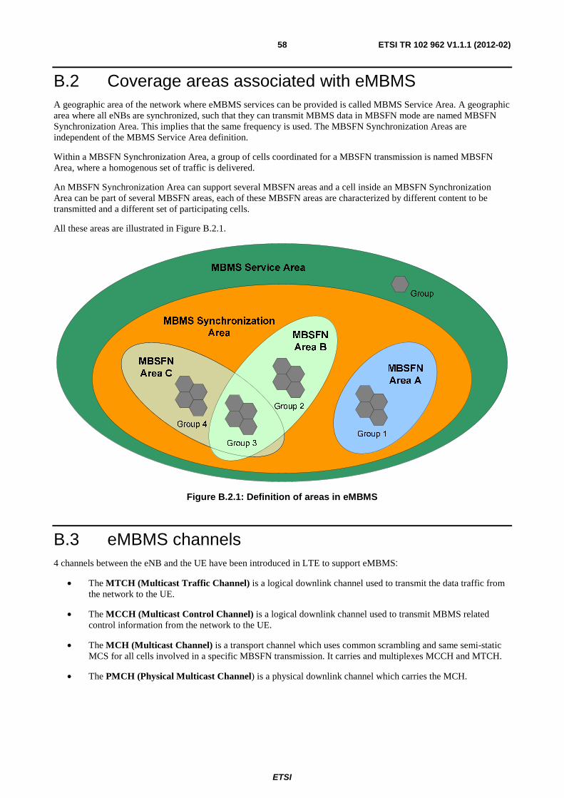
ETSI
ETSI TR 102 962 V1.1.1 (2012-02) 58
B.2 Coverage areas associated with eMBMS A geographic area of the network where eMBMS services can be provided is called MBMS Service Area. A geographic area where all eNBs are synchronized, such that they can transmit MBMS data in MBSFN mode are named MBSFN Synchronization Area. This implies that the same frequency is used. The MBSFN Synchronization Areas are independent of the MBMS Service Area definition.
Within a MBSFN Synchronization Area, a group of cells coordinated for a MBSFN transmission is named MBSFN Area, where a homogenous set of traffic is delivered.
An MBSFN Synchronization Area can support several MBSFN areas and a cell inside an MBSFN Synchronization Area can be part of several MBSFN areas, each of these MBSFN areas are characterized by different content to be transmitted and a different set of participating cells.
All these areas are illustrated in Figure B.2.1.
Group 1
MBSFN
Area A
Group 3
Group 2
Group 4
MBSFN
Area B
MBSFN
Area C
MBMS Synchronization
Area
MBMS Service Area
Group
Figure B.2.1: Definition of areas in eMBMS
B.3 eMBMS channels 4 channels between the eNB and the UE have been introduced in LTE to support eMBMS:
• The MTCH (Multicast Traffic Channel) is a logical downlink channel used to transmit the data traffic from the network to the UE.
• The MCCH (Multicast Control Channel) is a logical downlink channel used to transmit MBMS related control information from the network to the UE.
• The MCH (Multicast Channel) is a transport channel which uses common scrambling and same semi-static MCS for all cells involved in a specific MBSFN transmission. It carries and multiplexes MCCH and MTCH.
• The PMCH (Physical Multicast Channel) is a physical downlink channel which carries the MCH.
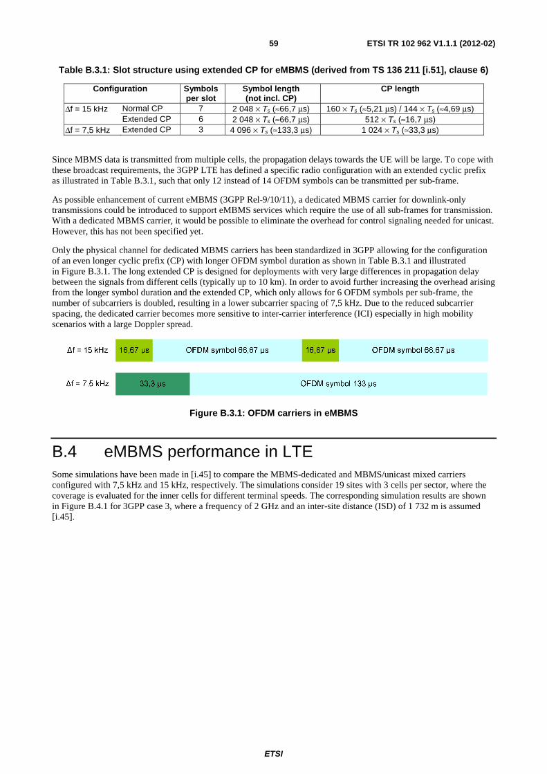
ETSI
ETSI TR 102 962 V1.1.1 (2012-02) 59
Table B.3.1: Slot structure using extended CP for eMBMS (derived from TS 136 211 [i.51], clause 6)
Configuration Symbols per slot
Symbol length (not incl. CP)
CP length
Δf = 15 kHz Normal CP 7 2 048 × Ts (≈66,7 μs) 160 × Ts (≈5,21 μs) / 144 × Ts (≈4,69 μs) Extended CP 6 2 048 × Ts (≈66,7 μs) 512 × Ts (≈16,7 μs)
Δf = 7,5 kHz Extended CP 3 4 096 × Ts (≈133,3 μs) 1 024 × Ts (≈33,3 μs)
Since MBMS data is transmitted from multiple cells, the propagation delays towards the UE will be large. To cope with these broadcast requirements, the 3GPP LTE has defined a specific radio configuration with an extended cyclic prefix as illustrated in Table B.3.1, such that only 12 instead of 14 OFDM symbols can be transmitted per sub-frame.
As possible enhancement of current eMBMS (3GPP Rel-9/10/11), a dedicated MBMS carrier for downlink-only transmissions could be introduced to support eMBMS services which require the use of all sub-frames for transmission. With a dedicated MBMS carrier, it would be possible to eliminate the overhead for control signaling needed for unicast. However, this has not been specified yet.
Only the physical channel for dedicated MBMS carriers has been standardized in 3GPP allowing for the configuration of an even longer cyclic prefix (CP) with longer OFDM symbol duration as shown in Table B.3.1 and illustrated in Figure B.3.1. The long extended CP is designed for deployments with very large differences in propagation delay between the signals from different cells (typically up to 10 km). In order to avoid further increasing the overhead arising from the longer symbol duration and the extended CP, which only allows for 6 OFDM symbols per sub-frame, the number of subcarriers is doubled, resulting in a lower subcarrier spacing of 7,5 kHz. Due to the reduced subcarrier spacing, the dedicated carrier becomes more sensitive to inter-carrier interference (ICI) especially in high mobility scenarios with a large Doppler spread.
Figure B.3.1: OFDM carriers in eMBMS
B.4 eMBMS performance in LTE Some simulations have been made in [i.45] to compare the MBMS-dedicated and MBMS/unicast mixed carriers configured with 7,5 kHz and 15 kHz, respectively. The simulations consider 19 sites with 3 cells per sector, where the coverage is evaluated for the inner cells for different terminal speeds. The corresponding simulation results are shown in Figure B.4.1 for 3GPP case 3, where a frequency of 2 GHz and an inter-site distance (ISD) of 1 732 m is assumed [i.45].
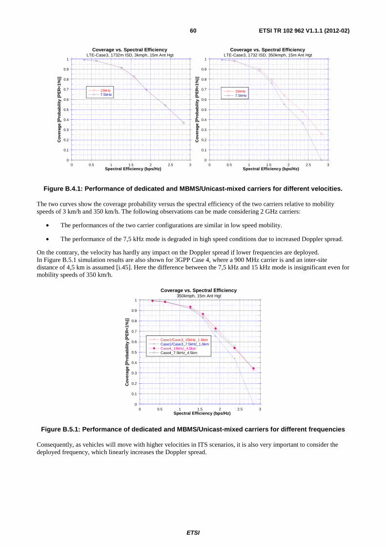
ETSI
ETSI TR 102 962 V1.1.1 (2012-02) 60
0
0.1
0.2
0.3
0.4
0.5
0.6
0.7
0.8
0.9
1
0 0.5 1 1.5 2 2.5 3
Coverage vs. Spectral EfficiencyLTE-Case3, 1732m ISD, 3kmph, 15m Ant Hgt
15kHz7.5kHz
Co
vera
ge
[Pro
bab
ility
(PE
R<
1%)]
Spectral Efficiency (bps/Hz)
0
0.1
0.2
0.3
0.4
0.5
0.6
0.7
0.8
0.9
1
0 0.5 1 1.5 2 2.5 3
Coverage vs. Spectral EfficiencyLTE-Case3, 1732 ISD, 350kmph, 15m Ant Hgt
15kHz7.5kHz
Co
vera
ge
[Pro
bab
ility
(PE
R<
1%)]
Spectral Efficiency (bps/Hz)
Figure B.4.1: Performance of dedicated and MBMS/Unicast-mixed carriers for different velocities.
The two curves show the coverage probability versus the spectral efficiency of the two carriers relative to mobility speeds of 3 km/h and 350 km/h. The following observations can be made considering 2 GHz carriers:
• The performances of the two carrier configurations are similar in low speed mobility.
• The performance of the 7,5 kHz mode is degraded in high speed conditions due to increased Doppler spread.
On the contrary, the velocity has hardly any impact on the Doppler spread if lower frequencies are deployed. In Figure B.5.1 simulation results are also shown for 3GPP Case 4, where a 900 MHz carrier is and an inter-site distance of 4,5 km is assumed [i.45]. Here the difference between the 7,5 kHz and 15 kHz mode is insignificant even for mobility speeds of 350 km/h.
0
0.1
0.2
0.3
0.4
0.5
0.6
0.7
0.8
0.9
1
0 0.5 1 1.5 2 2.5 3
Coverage vs. Spectral Efficiency350kmph, 15m Ant Hgt
Case1/Case3_15kHz_1.6kmCase1/Case3_7.5kHz_1.6kmCase4_15kHz_4.5kmCase4_7.5kHz_4.5km
Co
vera
ge
[Pro
bab
ility
(P
ER
<1%
)]
Spectral Efficiency (bps/Hz)
Figure B.5.1: Performance of dedicated and MBMS/Unicast-mixed carriers for different frequencies
Consequently, as vehicles will move with higher velocities in ITS scenarios, it is also very important to consider the deployed frequency, which linearly increases the Doppler spread.
ETSI
ETSI TR 102 962 V1.1.1 (2012-02) 61
B.5 Evaluation of eMBMS for the delivery of ITS services Based on the previous analysis, the following recommendations can be made:
• Preference of using 800 MHz to reduce the Doppler effect for highway scenario if this spectrum can be made available.
• Use of the LTE bandwidth flexibility from 1,4 MHz to 20 MHz to follow the demand of new services introduced by cooperative networks.
• Standardization of dedicated MBMS carrier transmission mode.
Further studies needed:
• Assessing the delay of E2E LTE transmissions to evaluate its capability to support short delay communications.
The eMBMS feature appears as being one of the most powerful solutions for the distribution of mobility and comfort services and also for traffic efficiency services according to ITS requirements. Thus, the efficient broadcast and multicast delivery of data will allow development of new services and reinforce the transmission capability for current ITS services.
The eMBMS link can be introduced in the IPv6/NEMO mobility architecture as specified in ETSI ITS to bring a high bit rate access link to the mobile router embedded in the OBU.
The introduction of an eMBMS link will also reinforce the global network capacity in the vehicular scenarios and the capability of multiplexing unicast and broadcast services in OFDM carriers will enrich the service offer in cooperative networks.
ETSI
ETSI TR 102 962 V1.1.1 (2012-02) 62
Annex C: Bibliography 3GPP TS 41.101: "Technical Specifications and Technical Reports for a GERAN-based 3GPP system".
3GPP TS 21.101: "Technical Specifications and Technical Reports for a UTRAN-based 3GPP system".
3GPP TS 21.201: "Technical Specifications and Technical Reports for an Evolved Packet System (EPS) based 3GPP system".
3GPP TS 21.202: "Technical Specifications and Technical Reports relating to the Common IP Multimedia Subsystem (IMS)".
ISO/NP 26862: "Transport information and control systems - Crash and emergency notification reference architecture".

ETSI
ETSI TR 102 962 V1.1.1 (2012-02) 63
History
Document history
V1.1.1 February 2012 Publication