integrated inp arbitrary waveform generation and detection...
TRANSCRIPT
Integrated InP Arbitrary Waveform Generation and Detection for THzGeneration and Detection for THz
Advanced Format Trx and RcvS J Ben YooS. J. Ben Yoo
UC Davis [email protected]:c o edge e ts
E. Ippen, F. Kaertner, L. Koldzijeski (MIT)J. P. Heritage, K. Okamoto, A-V Pham, R. Scott, F.Soares, J-H Baek,
X Zh N F t i D G i l S Ch A K l R Y (UCD i )X.Zhou, N. Fontaine, D. Geisler, S. Cheung, A. Kalarar, R. Yu (UCDavis)W.Tsang, K-Y Liou, G. Chu, R.Hamm, H.Huo, et al (Multiplex)
S. Lourdudoss, C.Junesand, F. Olsson, et al (KTH)S. Lourdudoss, C.Junesand, F. Olsson, et al (KTH)K. Nary, R.Coccioli, R.Johnson, N. Yeung, et al (Inphi)
1ECOC 2009
This work was supported in part by DARPA DSO and SPAWAR under OAWG contract HR0011-05-C-0155
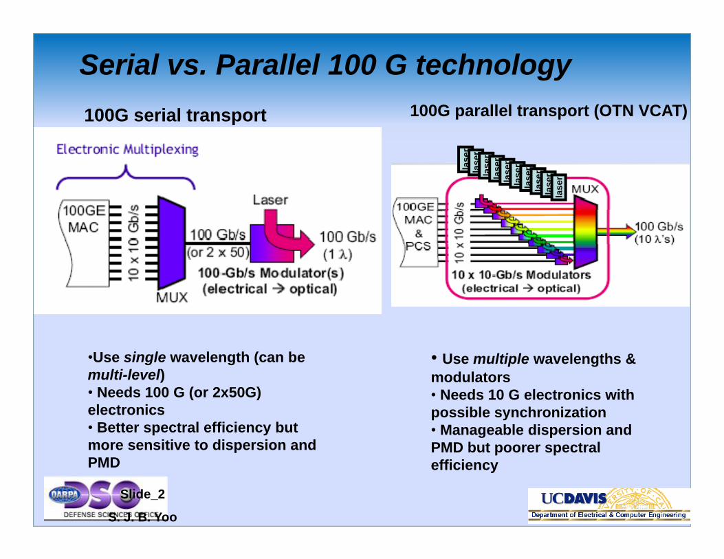
Serial vs. Parallel 100 G technology 100G serial transport
lase
rla
ser
aser
aser
ser
ser
er r r
100G parallel transport (OTN VCAT)
(b)
l la las
las
lase
lase
lase
rla
ser
(b)
•Use single wavelength (can be multi-level)
• Use multiple wavelengths & modulators
• Needs 100 G (or 2x50G) electronics• Better spectral efficiency but more sensitive to dispersion and
• Needs 10 G electronics with possible synchronization• Manageable dispersion and PMD but poorer spectral
Slide_2
S. J. B. Yoo
PMD efficiency
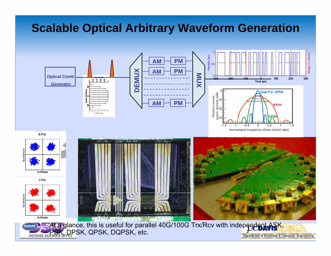
Scalable Optical Arbitrary Waveform Generation
0 0 0 0
Intensity (au)
0 0 0 0
Intensity (au)
0 0 0 0
Intensity (au)
0 0 0 0
Intensity (au)
AM PMAM PM
MU
X MU -300 -200 -100 0 100 200 300
0
0.5
1
Inte
nsity
(au)
-300 -200 -100 0 100 200 300
Pha
se (1
rad/
div)
Optical Comb
-500
500
0.2
0.4
0.6
0.8 1
Frequency (G
Hz)
-500
500
0.2
0.4
0.6
0.8 1
Frequency (G
Hz)
-500
500
0.2
0.4
0.6
0.8 1
Frequency (G
Hz)
-500
500
0.2
0.4
0.6
0.8 1
Frequency (G
Hz)
-500
50-3 -2 -1 0 1 2 3
AM PM
DEM
UX Time (ps)Time (ps)
Generator
3 2
Phase (rad)
3• At a glance, this is useful for parallel 40G/100G Trx/Rcv with independent ASK,
PSK, DPSK, QPSK, DQPSK, etc.
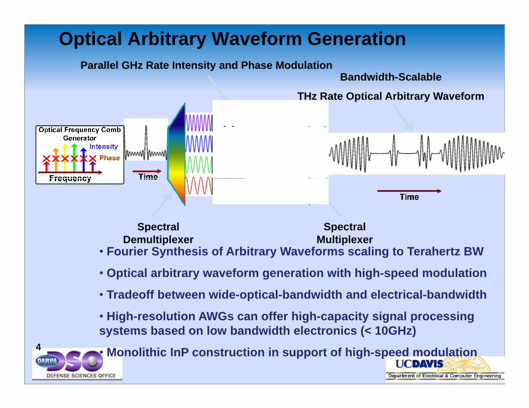
Optical Arbitrary Waveform GenerationParallel GHz Rate Intensity and Phase Modulation
Bandwidth Scalable
Am
Bandwidth-Scalable
THz Rate Optical Arbitrary Waveform
Am
Am
Am
Spectral
Am
SpectralSpectral Demultiplexer
Spectral Multiplexer
• Fourier Synthesis of Arbitrary Waveforms scaling to Terahertz BW
• Optical arbitrary waveform generation with high-speed modulation
• Tradeoff between wide-optical-bandwidth and electrical-bandwidth
• High-resolution AWGs can offer high-capacity signal processing systems based on low bandwidth electronics (< 10GHz)
4systems based on low bandwidth electronics (< 10GHz)
• Monolithic InP construction in support of high-speed modulation
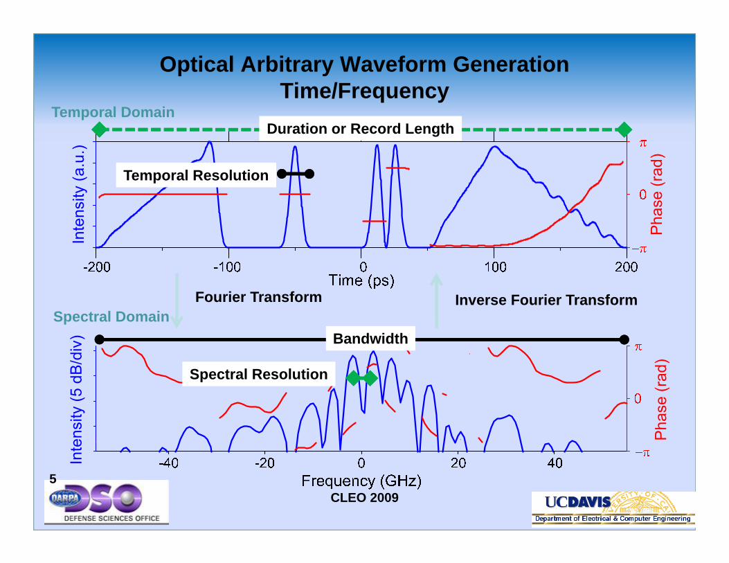
Optical Arbitrary Waveform Generation Time/Frequency
a.u.
)
ad)
Duration or Record Length
Temporal Resolution
Temporal Domain
Inte
nsity
(a
Pha
se (r
aTemporal Resolution
Fourier TransformSpectral Domain
Inverse Fourier Transform
dB/d
iv)
(rad
)
Spectral Domain
Spectral Resolution
Bandwidth
nten
sity
(5
Pha
se (
In
5CLEO 2009
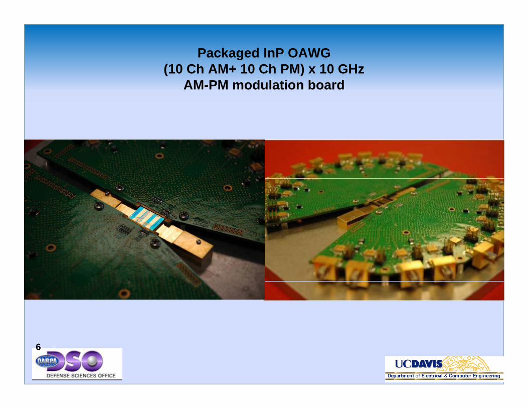
Packaged InP OAWG(10 Ch AM+ 10 Ch PM) x 10 GHz( )
AM-PM modulation board
6
OAWG: TW-EAEA pitch=150um
BCB opening = 3um
NbufferGND
BCB
Active
Nbuffer
Waveguide 11 W =3+1um Wvia = 20ummesa = 11um W =3+1um Wvia =
14umBCB on mesa etch stop
GND
•NiCr resistor 200um
•TL: sig-gnd-gap: 15-30-7
•TL: sig-gnd-gap: 15-30-11.5um•EA Length = 300um
•TL: sig-gnd-gap: 6-20-15um
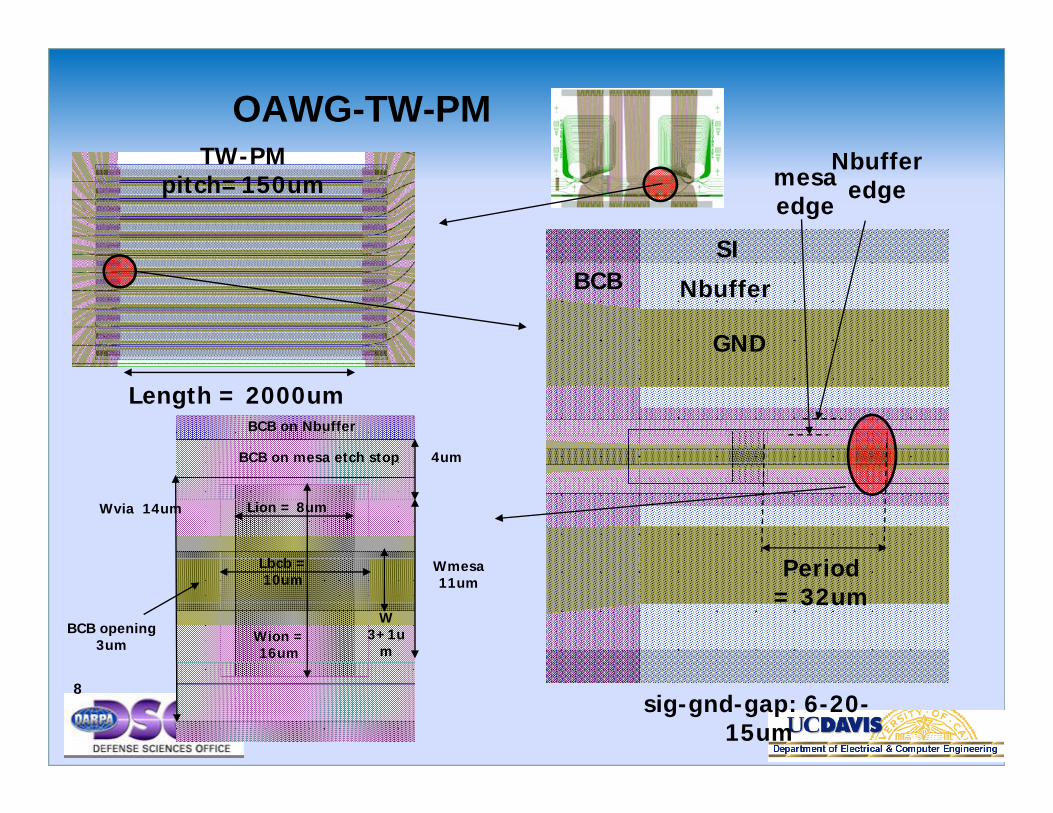
OAWG-TW-PMTW PMTW-PM
pitch=150um
SI
Nbuffer edge mesa
edge
SI
GND
NbufferBCB
Length = 2000um
BCB on mesa etch stop
BCB on Nbuffer
4um
Wvia 14um Lion = 8um
Lbcb
BCB on mesa etch stop
P i d
4um
Wmesa 11um
BCB opening 3um Wion =
16um
Lbcb = 10um
W 3+1u
m
Period = 32um
8sig-gnd-gap: 6-20-
15um
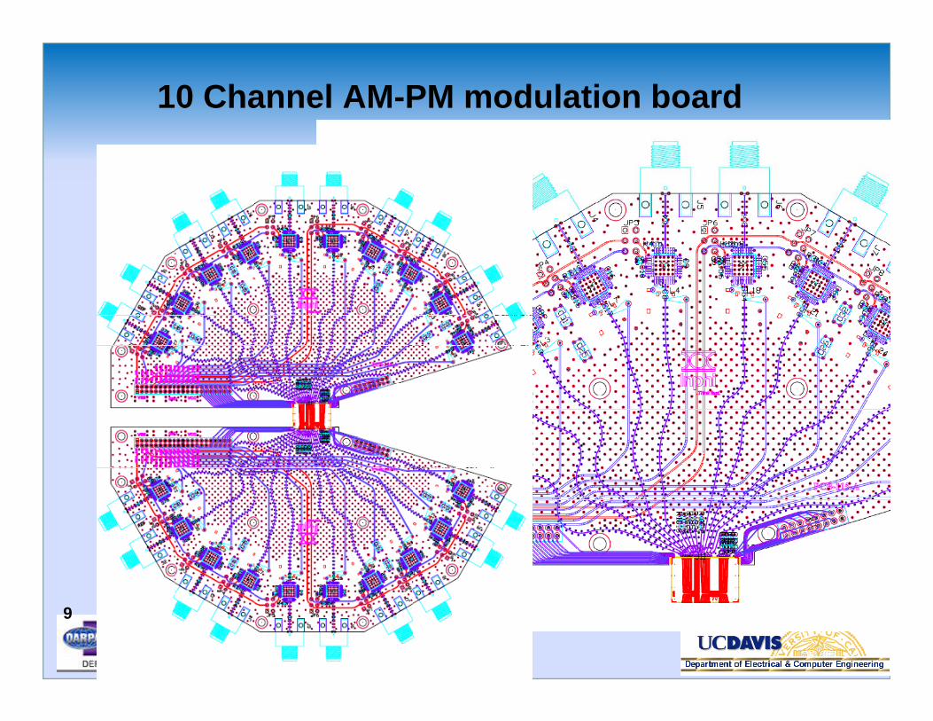
10 Channel AM-PM modulation board
9
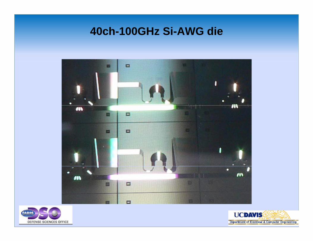
40ch-100GHz Si-AWG die
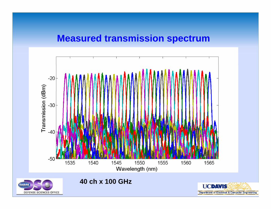
Measured transmission spectrumMeasured transmission spectrum
40 ch x 100 GHz
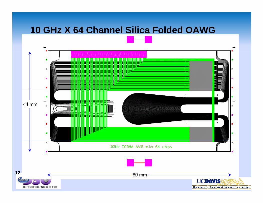
10 GHz X 64 Channel Silica Folded OAWG
12
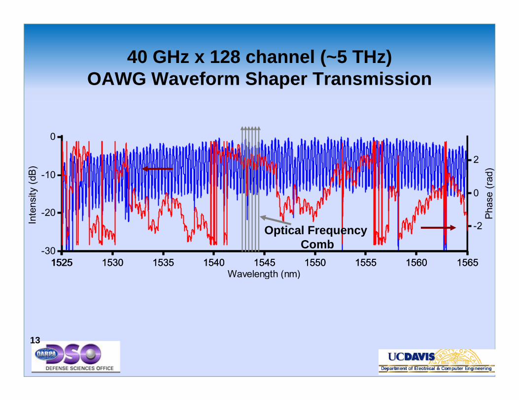
40 GHz x 128 channel (~5 THz) OAWG W f Sh T i iOAWG Waveform Shaper Transmission
10
0
B) 2
d)
-20
-10
Inte
nsity
(dB
2
0
Phas
e (r
ad
1525 1530 1535 1540 1545 1550 1555 1560 1565-30
Wavelength (nm)1525 1530 1535 1540 1545 1550 1555 1560 1565
-2Optical FrequencyComb
Wavelength (nm)
13
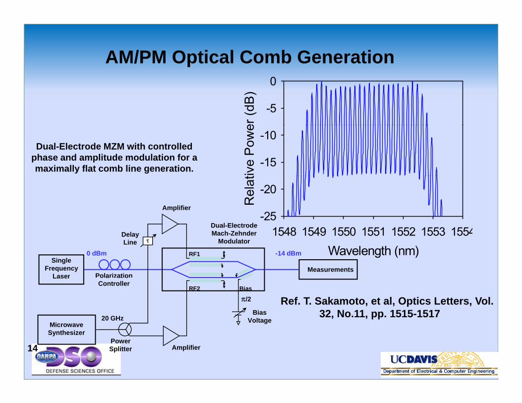
AM/PM Optical Comb Generation
er (d
B)
-5
0
Dual-Electrode MZM with controlled phase and amplitude modulation for a maximally flat comb line generation. tiv
e P
owe
-15
-10
Dual-Electrode
Amplifier Rel
at
-25
-20
RF1
Polarization
Dual Electrode Mach-Zehnder
Modulator
Single Frequency
LaserMeasurements
Delay Line
0 dBm -14 dBm Wavelength (nm)1548 1549 1550 1551 1552 1553 1554
RF2 Bias
o a at oController
Laser
Microwave
Bias Voltage
/2
20 GHz
Ref. T. Sakamoto, et al, Optics Letters, Vol. 32, No.11, pp. 1515-1517
SynthesizerPower Splitter Amplifier14
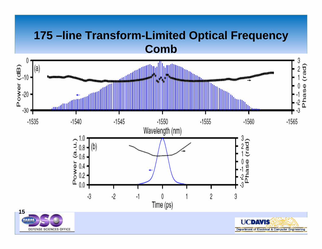
175 –line Transform-Limited Optical Frequency C bComb
15
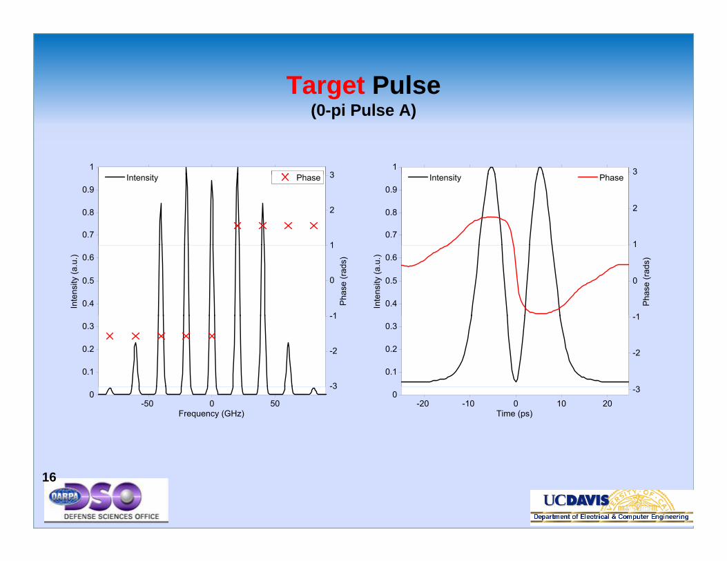
Target Pulse ( )(0-pi Pulse A)
1 I i 3
Ph
1 I i
3 Ph
0.7
0.8
0.9Intensity
1
2
3Phase
0.7
0.8
0.9Intensity
1
2
Phase
0.4
0.5
0.6
Inte
nsity
(a.u
.)
-1
0
1
Pha
se (r
ads)
0.4
0.5
0.6
Inte
nsity
(a.u
.)
1
0
1
Phas
e (ra
ds)
0.1
0.2
0.3
-3
-2
-1
0.1
0.2
0.3
3
-2
-1
-50 0 500
Frequency (GHz)
-3
-20 -10 0 10 20
0
Time (ps)
-3
16
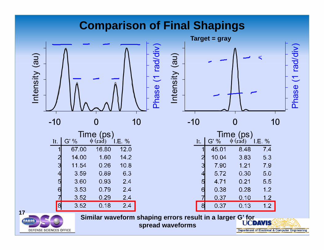
Comparison of Final Shapings
) )Target = grayty
(au)
1 ra
d/di
v
ty (a
u)
1 ra
d/di
v
Inte
nsit
Phas
e (1
Inte
nsit
Phas
e (1
-10 0 10Time (ps)
-10 0 10 -10 0 10Time (ps)
-10 0 10
Similar waveform shaping errors result in a larger G’ for spread waveforms
17
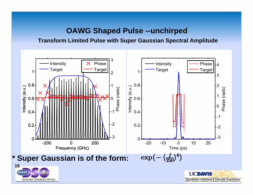
OAWG Shaped Pulse --unchirpedTransform Limited Pulse with Super Gaussian Spectral Amplitude
3
0 8
1
IntensityTarget
0 8
1
IntensityTarget
1
2
3PhaseTarget
0 8
1
IntensityTarget
2
3
4PhaseTarget
0.6
0.8
nten
sity
(a.u
.)
0.6
0.8
nten
sity
(a.u
.)
1
0
1
Pha
se (r
ads)
0.6
0.8
nten
sity
(a.u
.)
0
1
2
Pha
se (r
ads)
0.2
0.4In
0.2
0.4In
-2
-1 P
0.2
0.4In-2
-1
P
-200 0 2000
Frequency (GHz)
-200 0 200
0
Frequency (GHz)
-3 -20 -10 0 10 20
0
Time (ps)
-3
* Super Gaussian is of the form:18 Super Gaussian is of the form:
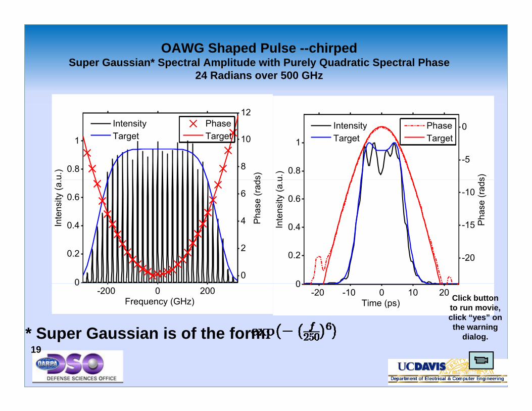
OAWG Shaped Pulse --chirpedSuper Gaussian* Spectral Amplitude with Purely Quadratic Spectral Phase
24 Radians over 500 GHz24 Radians over 500 GHz
Intensity
12 Phase
Intensity 0
Phase
0.8
1
u.)
yTarget
8
10
s)
Target
0.8
1
u.)
IntensityTarget
-5
0
s)
PhaseTarget
0.4
0.6
Inte
nsity
(a.
4
6
Pha
se (r
ad
0.4
0.6
Inte
nsity
(a.u
-15
-10
Pha
se (r
ads
0
0.2
0
2
0
0.2 -20
-200 0 2000
Frequency (GHz)
-20 -10 0 10 20
0
Time (ps)
* Super Gaussian is of the form:
Click button to run movie, click “yes” on the warning
dialog Super Gaussian is of the form: 19
dialog.
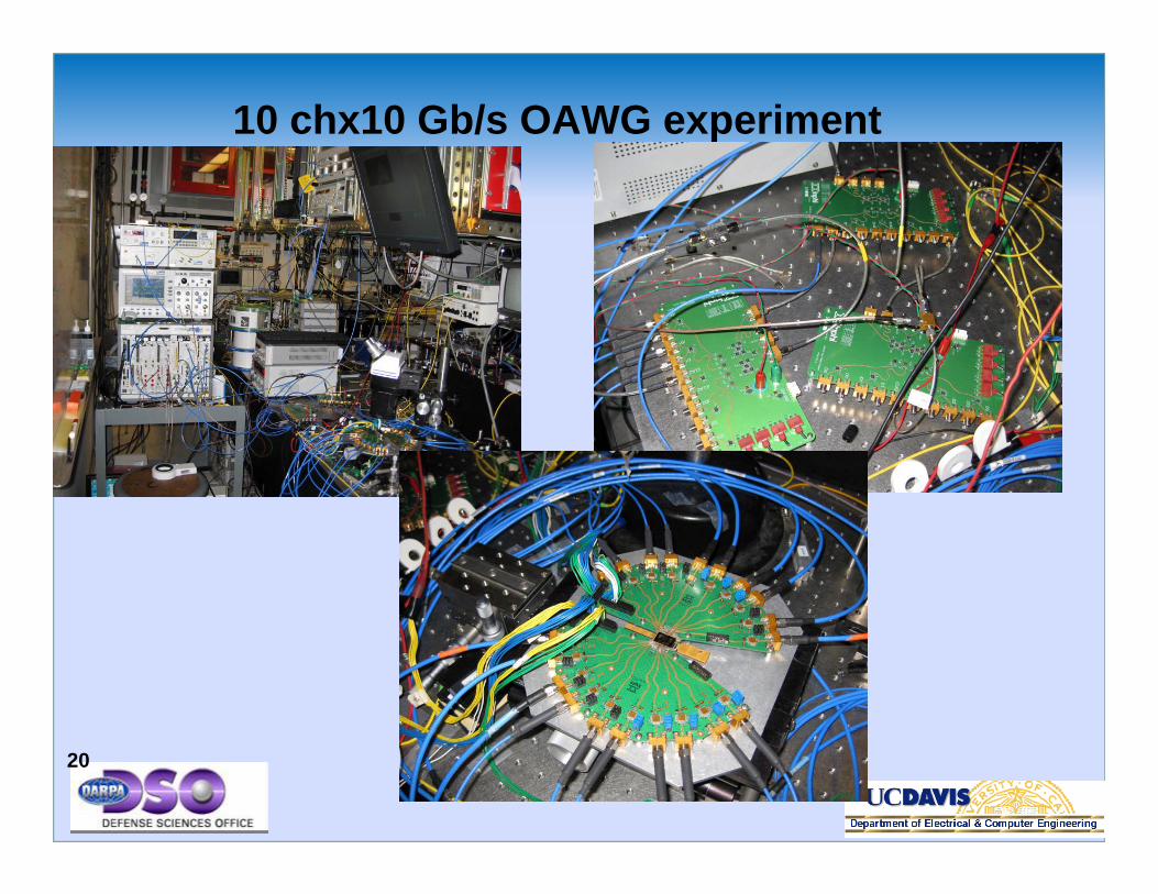
10 chx10 Gb/s OAWG experiment
20
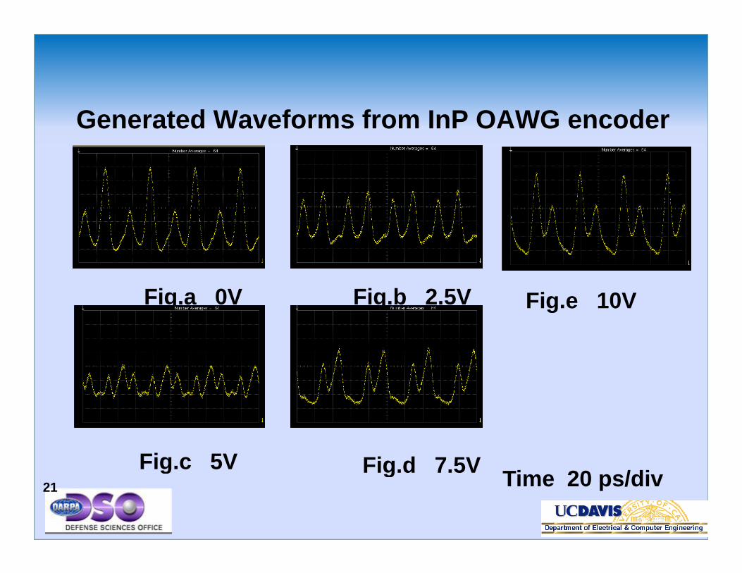
Generated Waveforms from InP OAWG encoder
Fig.a 0V Fig.b 2.5V Fig.e 10V
Fig.c 5V Fig d 7 5V21
Fig.c 5VTime 20 ps/divFig.d 7.5V
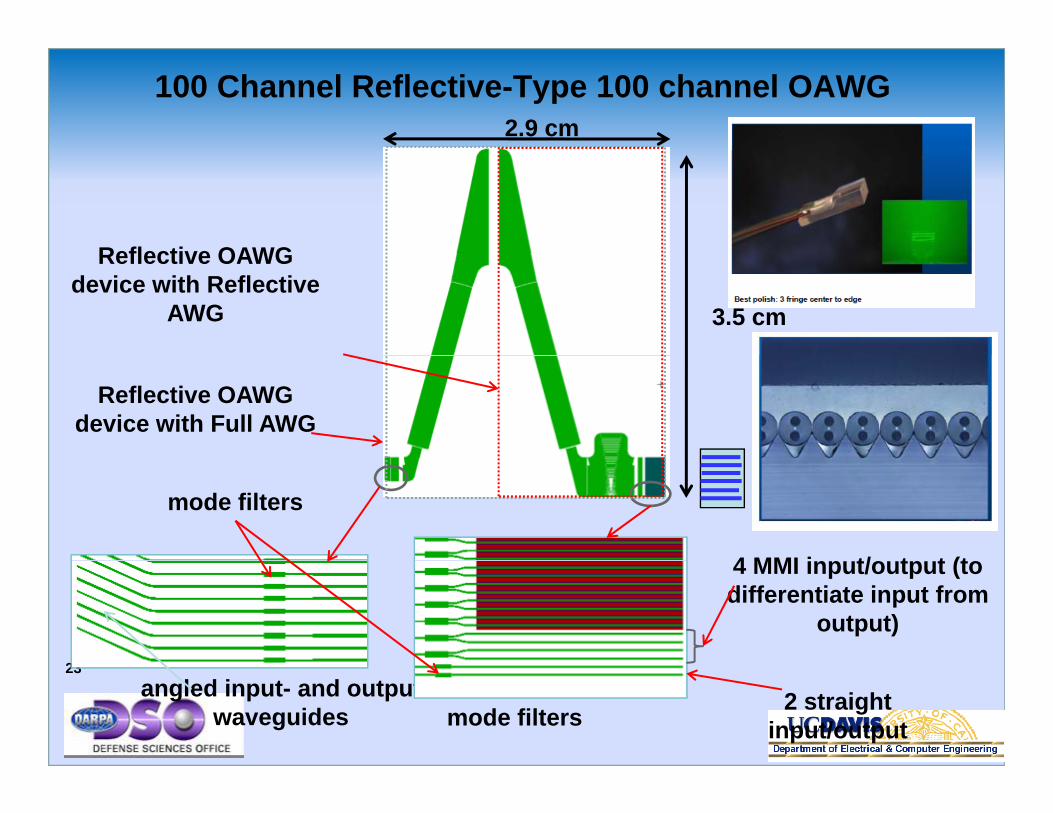
100 Channel Reflective-Type 100 channel OAWG 2.9 cm
Reflective OAWG
3.5 cm
Reflective OAWG device with Reflective
AWG
Reflective OAWG device with Full AWG
mode filters
4 MMI i t/ t t (t
23
4 MMI input/output (to differentiate input from
output)
23angled input- and output
waveguides mode filters 2 straight input/output
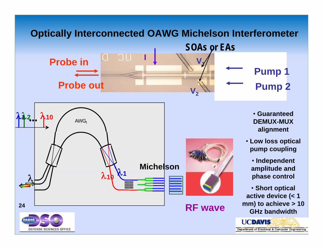
Optically Interconnected OAWG Michelson InterferometerSOAs or EAsSOAs or EAs
IProbe in V1Pump 1
Probe out V2Pump 2
12 101AWG
• Guaranteed DEMUX-MUX
alignment
• Low loss optical
1Michelson
• Low loss optical pump coupling
• Independent amplitude and
110
pphase control
• Short optical active device (< 1
mm) to achieve > 1024 RF wave mm) to achieve > 10 GHz bandwidth
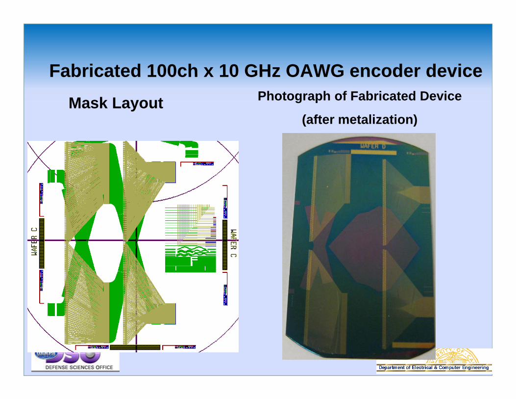
Fabricated 100ch x 10 GHz OAWG encoder deviceFabricated 100ch x 10 GHz OAWG encoder deviceMask Layout Photograph of Fabricated Device
(after metalization)( )
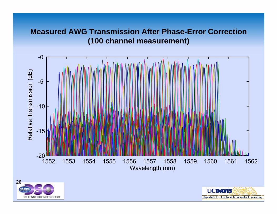
Measured AWG Transmission After Phase-Error Correction(100 channel measurement)(100 channel measurement)
-0
-5
-10
-15
1552 1553 1554 1555 1556 1557 1558 1559 1560 1561 1562-20
Wavelength (nm)
26
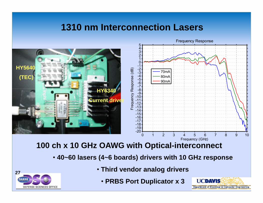
1310 nm Interconnection Lasers
012345
Frequency Response
HY6340
HY5640
(TEC)
8-7-6-5-4-3-2-10
espo
nse
(dB) 70mA
80mA90mA
HY6340
Current driver
-15-14-13-12-11-10-9-8
Freq
uenc
y R
e0 1 2 3 4 5 6 7 8 9 10
-20-19-18-17-1615
Frequency (GHz)
Frequency (GHz)
• 40~60 lasers (4~6 boards) drivers with 10 GHz response
100 ch x 10 GHz OAWG with Optical-interconnect
27 • Third vendor analog drivers
• PRBS Port Duplicator x 3
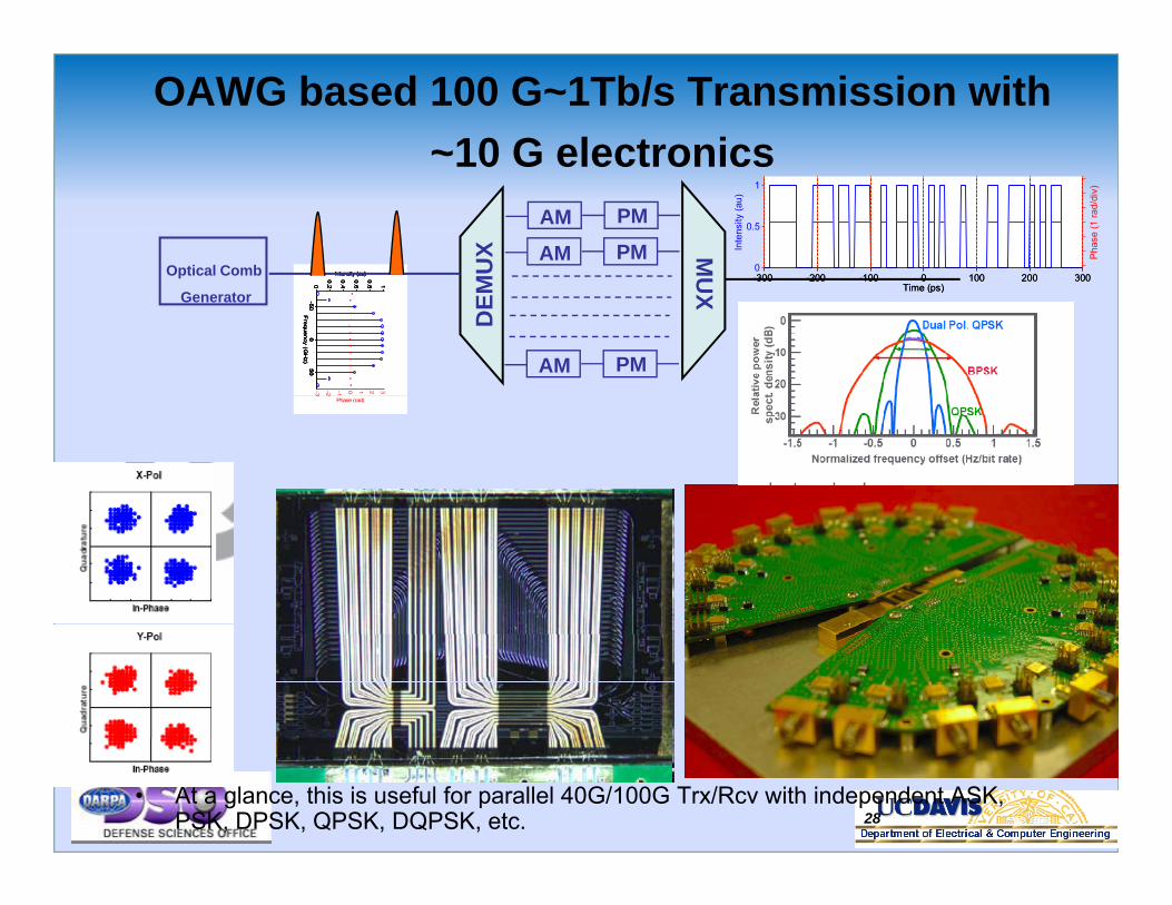
OAWG based 100 G~1Tb/s Transmission with ~10 G electronics
0 0 0 0
Intensity (au)
0 0 0 0
Intensity (au)
0 0 0 0
Intensity (au)
0 0 0 0
Intensity (au)
AM PMAM PM
MU
X MU -300 -200 -100 0 100 200 300
0
0.5
1
Inte
nsity
(au)
-300 -200 -100 0 100 200 300
Pha
se (1
rad/
div)
Optical Comb
-500
500
0.2
0.4
0.6
0.8 1
Frequency (G
Hz)
-500
500
0.2
0.4
0.6
0.8 1
Frequency (G
Hz)
-500
500
0.2
0.4
0.6
0.8 1
Frequency (G
Hz)
-500
500
0.2
0.4
0.6
0.8 1
Frequency (G
Hz)
-500
50-3 -2 -1 0 1 2 3
AM PM
DEM
UX Time (ps)Time (ps)
Generator
3 2
Phase (rad)
28• At a glance, this is useful for parallel 40G/100G Trx/Rcv with independent ASK,
PSK, DPSK, QPSK, DQPSK, etc.
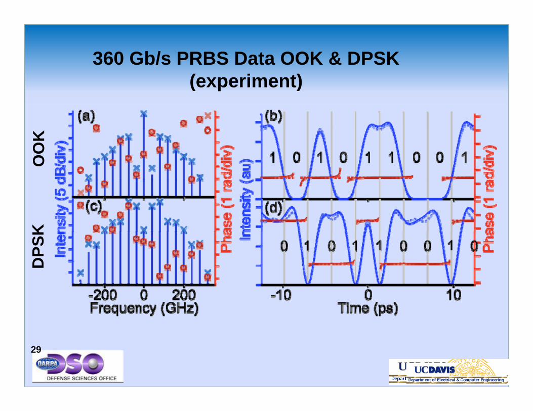
360 Gb/s PRBS Data OOK & DPSK ( i t)(experiment)
OO
KK
DPS
K
29
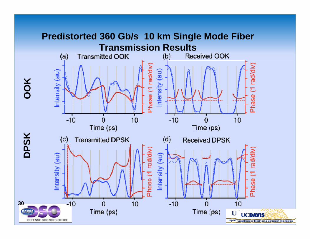
Predistorted 360 Gb/s 10 km Single Mode Fiber T i i R ltTransmission Results
OO
KK
DPS
K
30
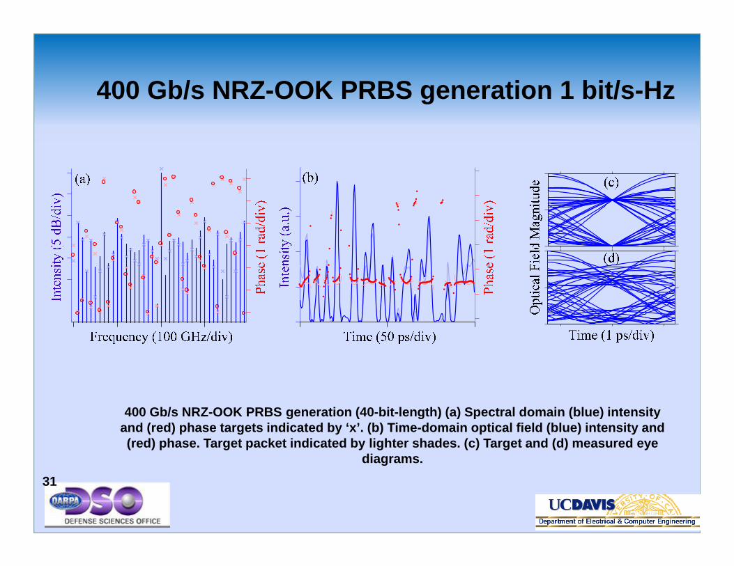
400 Gb/s NRZ-OOK PRBS generation 1 bit/s-Hz
400 Gb/s NRZ-OOK PRBS generation (40-bit-length) (a) Spectral domain (blue) intensity and (red) phase targets indicated by ‘x’. (b) Time-domain optical field (blue) intensity and (red) phase. Target packet indicated by lighter shades. (c) Target and (d) measured eye
diagrams.diagrams.
31
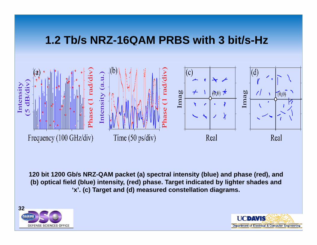
1.2 Tb/s NRZ-16QAM PRBS with 3 bit/s-Hz
120 bit 1200 Gb/s NRZ-QAM packet (a) spectral intensity (blue) and phase (red), and (b) optical field (blue) intensity, (red) phase. Target indicated by lighter shades and
‘x’. (c) Target and (d) measured constellation diagrams.
32
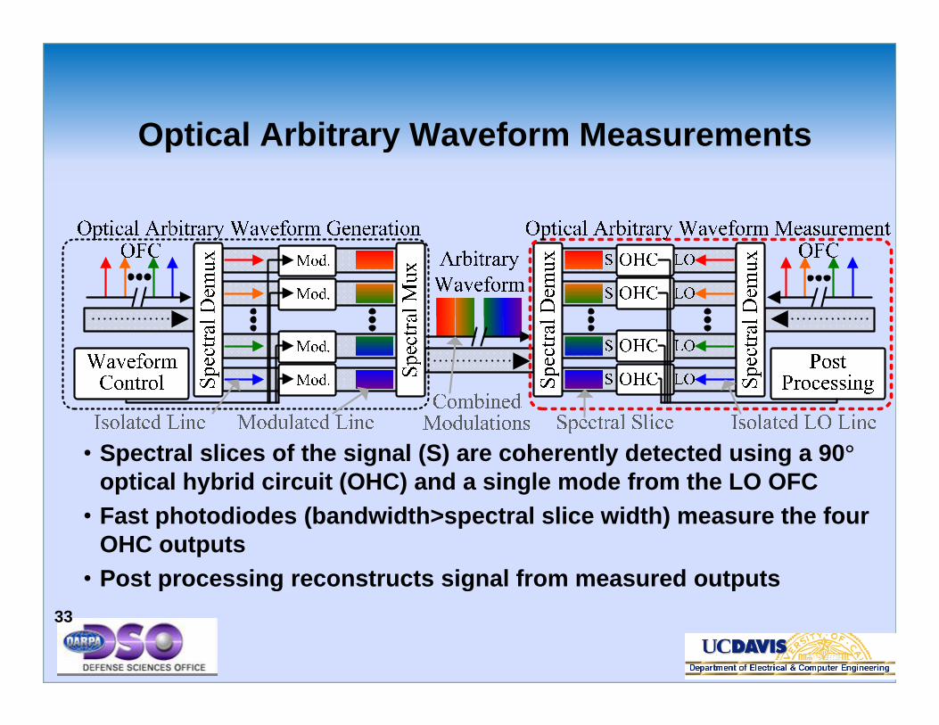
Optical Arbitrary Waveform MeasurementsOptical Arbitrary Waveform Measurements
• Spectral slices of the signal (S) are coherently detected using a 90°optical hybrid circuit (OHC) and a single mode from the LO OFC
• Fast photodiodes (bandwidth>spectral slice width) measure the four OHC outputs
• Post processing reconstructs signal from measured outputs33
g g
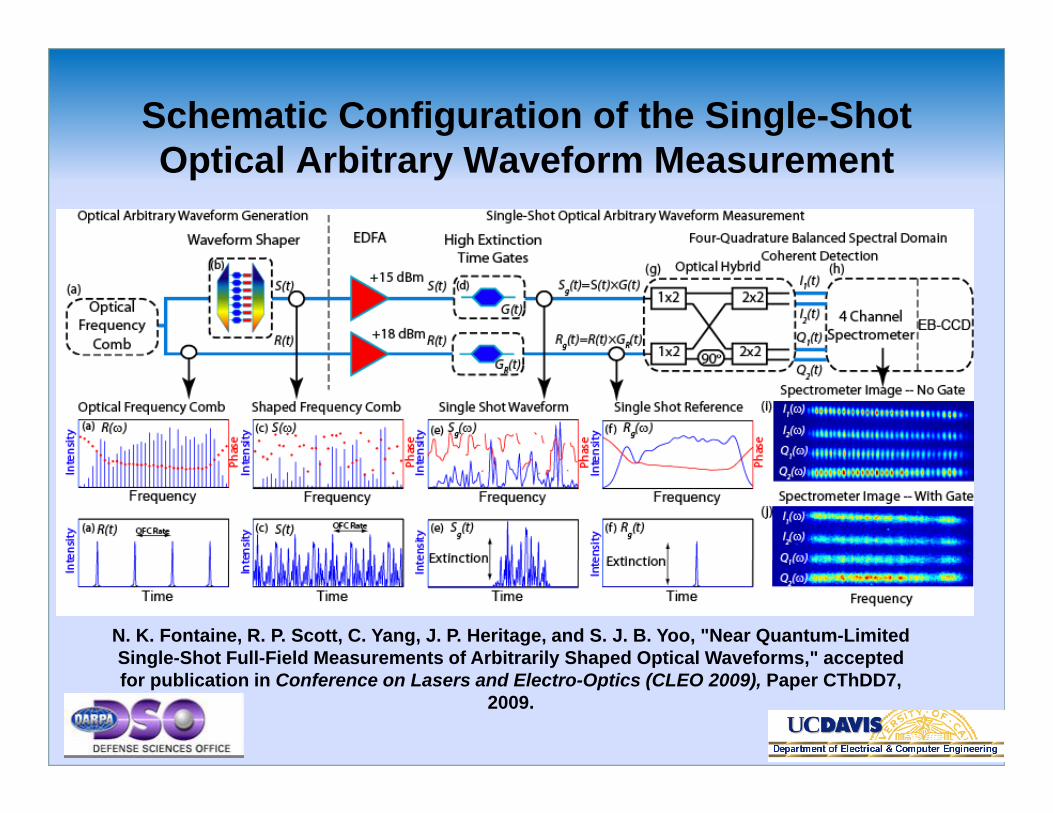
Schematic Configuration of the Single-Shot O ti l A bit W f M tOptical Arbitrary Waveform Measurement
N. K. Fontaine, R. P. Scott, C. Yang, J. P. Heritage, and S. J. B. Yoo, "Near Quantum-Limited Single-Shot Full-Field Measurements of Arbitrarily Shaped Optical Waveforms," acceptedSingle Shot Full Field Measurements of Arbitrarily Shaped Optical Waveforms, accepted for publication in Conference on Lasers and Electro-Optics (CLEO 2009), Paper CThDD7,
2009.
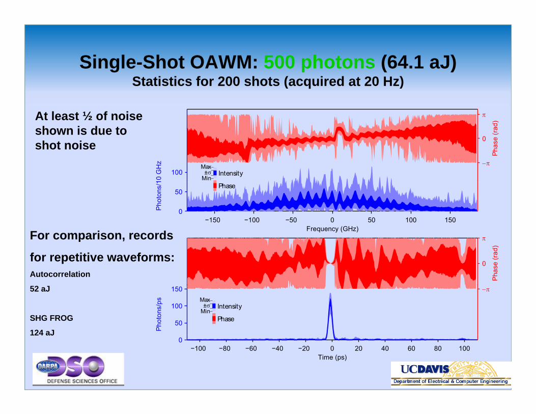
Single-Shot OAWM: 500 photons (64.1 aJ)St ti ti f 200 h t ( i d t 20 H )Statistics for 200 shots (acquired at 20 Hz)
ad)At least ½ of noise
shown is due to
100
0 G
Hz
0
Phas
e (r
a
IntensityMax
Min±
shown is due to shot noise
−150 −100 −50 0 50 100 1500
50
Phot
ons/
1
Frequency (GHz)
Phase
For comparison records
0
Phas
e (r
ad)
For comparison, records
for repetitive waveforms:Autocorrelation
0
50
100
150
Phot
ons/
ps
Phase
IntensityMax
Min±
52 aJ
SHG FROG
124 aJ
−100 −80 −60 −40 −20 0 20 40 60 80 1000
Time (ps)
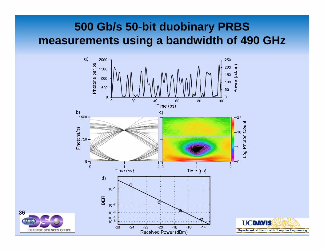
500 Gb/s 50-bit duobinary PRBS measurements using a bandwidth of 490 GHzg
36
Photonic Integrated Transceivers for Advanced Modulation FormatsModulation Formats
• THz scale Trx and Rcv– Serial modulation schemes will be limited in capacity
WDM combination will limit spectral efficiency– WDM combination will limit spectral efficiency– OAWG/OAWM schemes will allow THz and beyond
scaleability with full support of any modulation format of any shape & any multiplexing schemes (e.g. CO-OFDM, CO-WDM, p y p g ( g , ,etc)
• OAWG/OAWM– Energy-efficient low frequency electronics (e.g. 10 GHz)Energy efficient low frequency electronics (e.g. 10 GHz)– Coherent optical synthesis to scale up to THz and beyond– Supports any format/protocol incl. OFDM, CO-OFDM, CO-
WDM,,– Resiliency against failures of modulators or drivers.– Monolithic and Hybrid integration possible– Benefits from quantum limited detection in amplitude/phaseBenefits from quantum limited detection in amplitude/phase
37
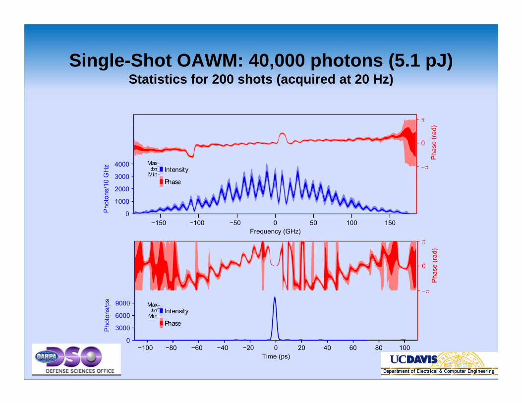
Single-Shot OAWM: 40,000 photons (5.1 pJ)St ti ti f 200 h t ( i d t 20 H )Statistics for 200 shots (acquired at 20 Hz)
3000
4000
GH
z
0
Phas
e (r
ad)
IntensityMax
Min±
−150 −100 −50 0 50 100 1500
1000
2000
3000
Phot
ons/
10 G
PhaseMin
Frequency (GHz)
0
hase
(rad
)
3000
6000
9000
Phot
ons/
ps
Ph
Phase
IntensityMax
Min±
0
3000P
−100 −80 −60 −40 −20 0 20 40 60 80 100Time (ps)
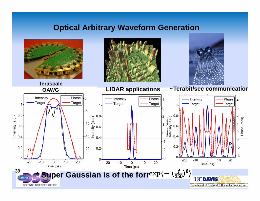
Optical Arbitrary Waveform Generation
Terascale O G LIDAR li ti Terabit/sec communication
1
IntensityTarget
-5
0
PhaseTarget
1
IntensityTarget
3
4
PhaseTarget 1
IntensityTarget
3
4
PhaseTarget
OAWG LIDAR applications ~Terabit/sec communication
0.4
0.6
0.8
Inte
nsity
(a.u
.)
-15
-10
Pha
se (r
ads)
0.4
0.6
0.8
Inte
nsity
(a.u
.)
0
1
2
Pha
se (r
ads)
0.4
0.6
0.8
Inte
nsity
(a.u
.)
0
1
2
Phas
e (ra
ds)
-20 -10 0 10 200
0.2
-20
-20 -10 0 10 20
0
0.2
0.4
-3
-2
-1
-20 -10 0 10 200
0.2
Time (ps)
-3
-2
-1
Time (ps)
* Super Gaussian is of the form: Time (ps)
Time (ps)
39
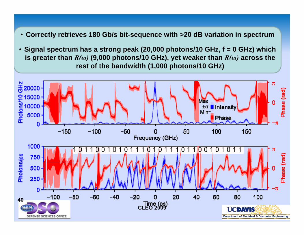
Example of FQSI Dynamic Range• Correctly retrieves 180 Gb/s bit-sequence with >20 dB variation in spectruma p e o QS y a c a ge• Signal spectrum has a strong peak (20,000 photons/10 GHz, f = 0 GHz) which
is greater than R(ω) (9,000 photons/10 GHz), yet weaker than R(ω) across the rest of the bandwidth (1,000 photons/10 GHz)
40CLEO 2009
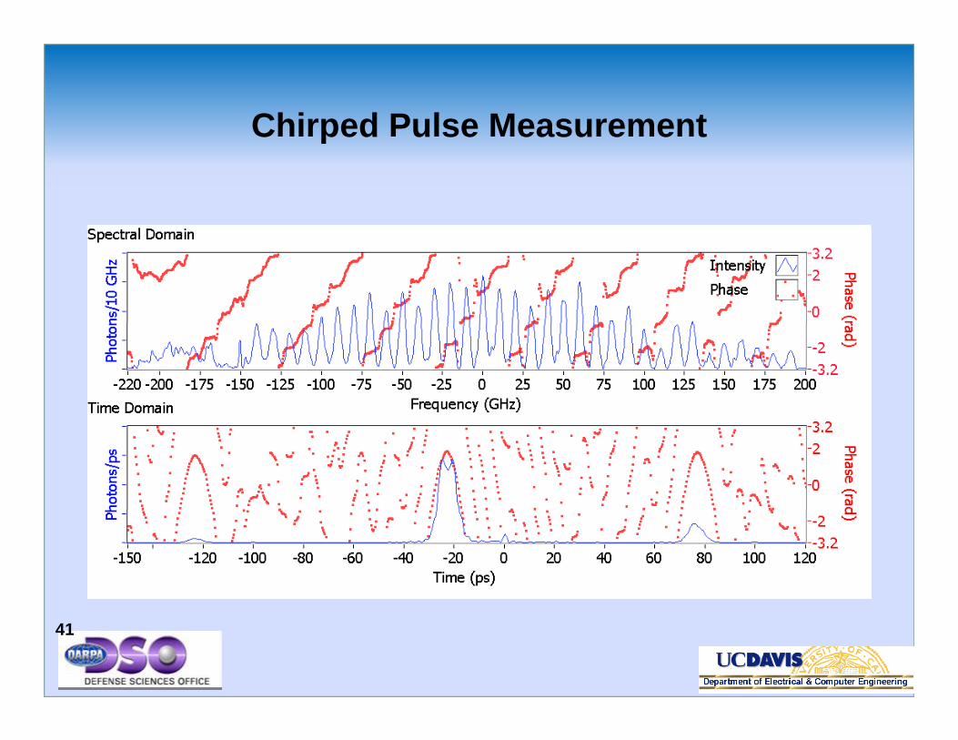
Chirped Pulse MeasurementC ped u se easu e e t
41
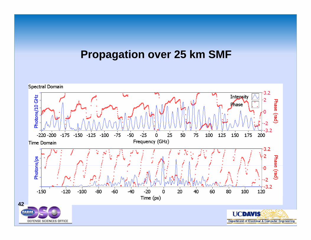
Propagation over 25 km SMF
42
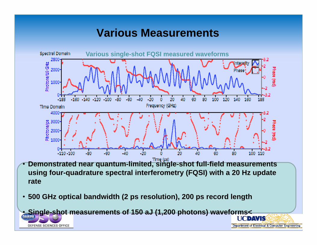
Various Measurements
Various single-shot FQSI measured waveforms
• Demonstrated near quantum-limited, single-shot full-field measurements using four-quadrature spectral interferometry (FQSI) with a 20 Hz update rate
• 500 GHz optical bandwidth (2 ps resolution), 200 ps record lengthp ( p ), p g
• Single-shot measurements of 150 aJ (1,200 photons) waveforms<
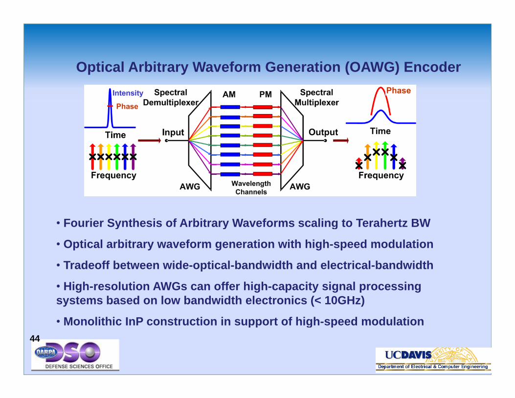
Optical Arbitrary Waveform Generation (OAWG) Encoder p y ( )
• Fourier Synthesis of Arbitrary Waveforms scaling to Terahertz BW• Fourier Synthesis of Arbitrary Waveforms scaling to Terahertz BW
• Optical arbitrary waveform generation with high-speed modulation
• Tradeoff between wide-optical-bandwidth and electrical-bandwidth
• High-resolution AWGs can offer high-capacity signal processing systems based on low bandwidth electronics (< 10GHz)
• Monolithic InP construction in support of high-speed modulationMonolithic InP construction in support of high speed modulation44
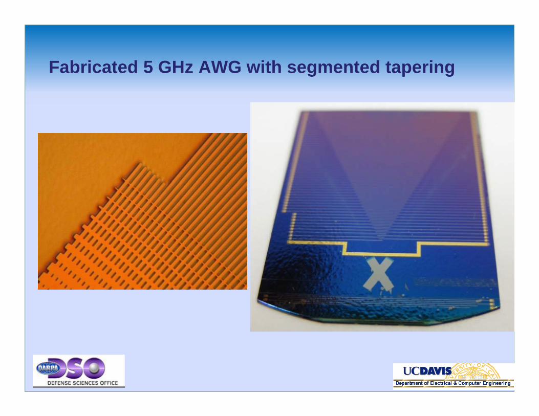
Fabricated 5 GHz AWG with segmented tapering
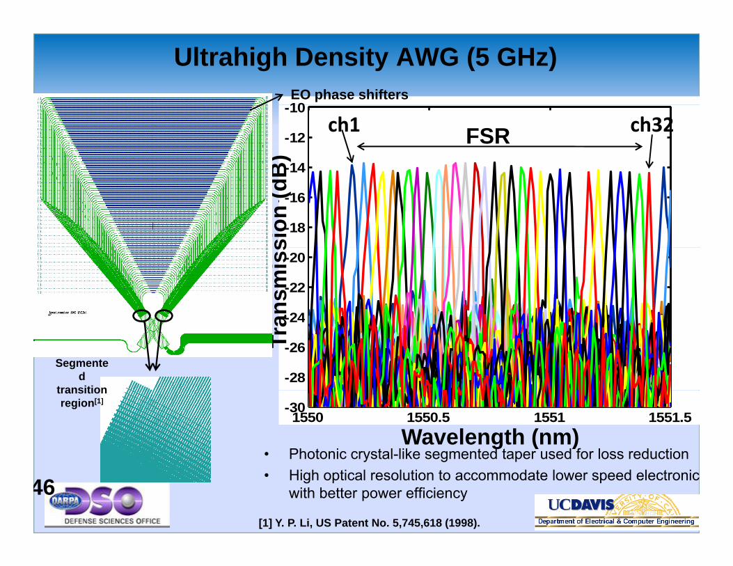
Ultrahigh Density AWG (5 GHz)
10EO phase shifters
-14
-12
-10ch1 ch32FSR
B)
-18
-16
()
sion
(dB
iber
-24
-22
-20
ansm
iss
ber-
to-F
-28
-26
-24
Tra
Fib
Segmented
transition
1550 1550.5 1551 1551.5-30
Wavelength (nm)• Photonic crystal-like segmented taper used for loss reduction
transition region[1]
y g p• High optical resolution to accommodate lower speed electronic
with better power efficiency
[1] Y. P. Li, US Patent No. 5,745,618 (1998).
46
Static OAWG– Integrated Fourier Domain line-by-line Pulse shaping
•Static or DC phase and amplitude modulation p pPhase Modulators Intensity Modulators
Spectral Multiplexer
Spectral Deultiplexer
Input Optical Frequency
Comb
Shaped Optical Frequency
Comb
Shape an Optical Full control of
waveform within 1 periodFrequency Inverse Fourier
Transform
period
Frequency Domain Time Domain48
CLEO 2009
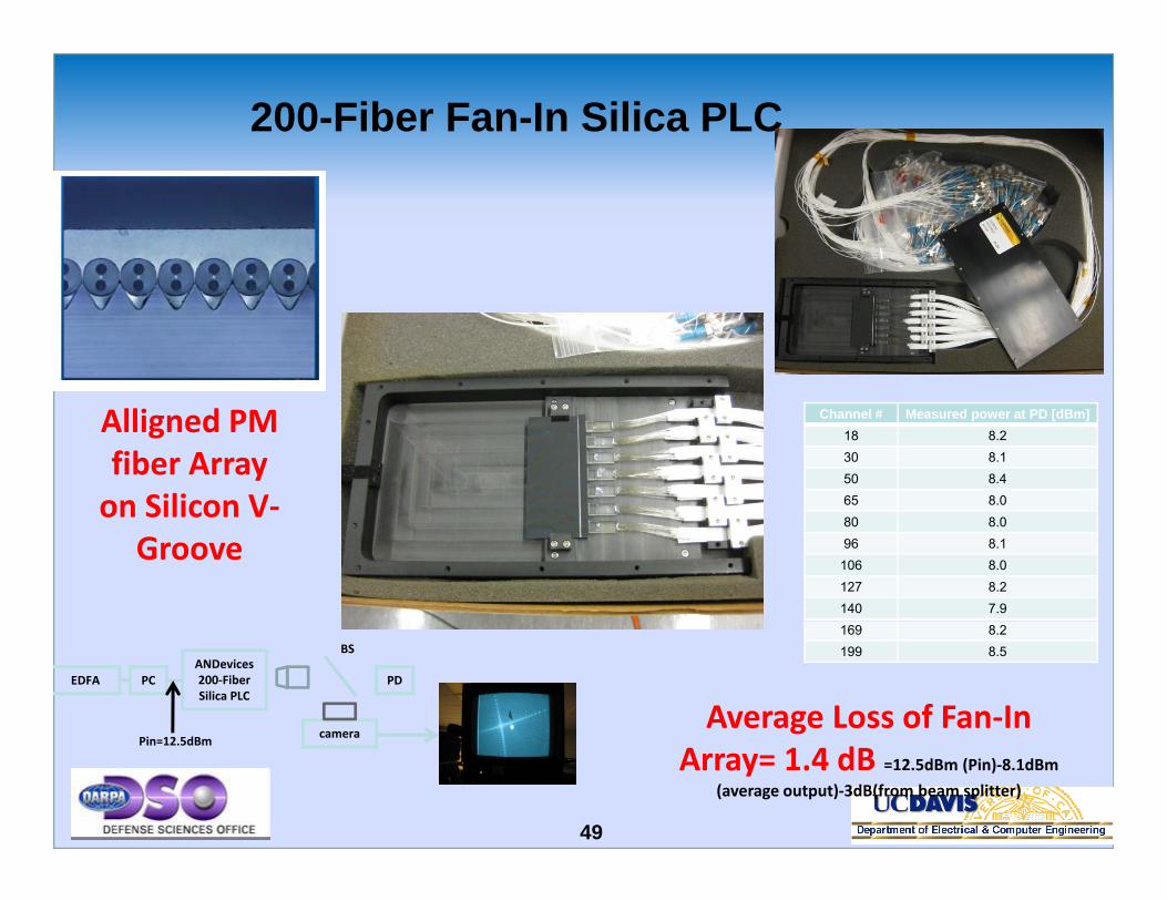
200-Fiber Fan-In Silica PLC
Channel # Measured power at PD [dBm]18 8.230 8.150 8.465 8.0
Alligned PM fiber Array on Silicon V‐
80 8.096 8.1
106 8.0127 8.2140 7.9
on Silicon V‐Groove
EDFA PCANDevices200‐Fiber Silica PLC
PD
camera
BS169 8.2199 8.5
Average Loss of Fan‐In camera
Pin=12.5dBm
Array= 1.4 dB =12.5dBm (Pin)‐8.1dBm
(average output)‐3dB(from beam splitter)
49
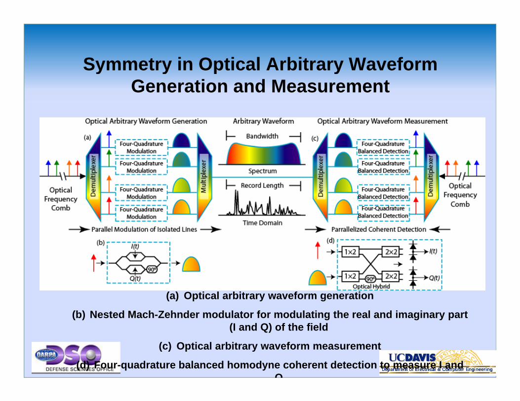
Symmetry in Optical Arbitrary Waveform Generation and Measurement
(a) Optical arbitrary waveform generation
(b) Nested Mach-Zehnder modulator for modulating the real and imaginary part (I and Q) of the field(I and Q) of the field
(c) Optical arbitrary waveform measurement
(d) Four-quadrature balanced homodyne coherent detection to measure I and Q
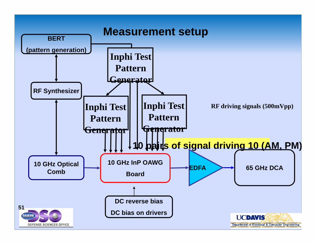
Measurement setupBERT
(pattern generation)Inphi Test
Pattern
RF SynthesizerGenerator
RF driving signals (500mVpp)Inphi Test Inphi Test RF driving signals (500mVpp)Inphi Test Pattern
Generator
Inphi Test Pattern
Generator
10 GHz Optical 10 GHz InP OAWGEDFA 65 GHz DCA
10 pairs of signal driving 10 (AM, PM)
Comb Board
DC bi
EDFA 65 GHz DCA
51DC reverse bias
DC bias on drivers
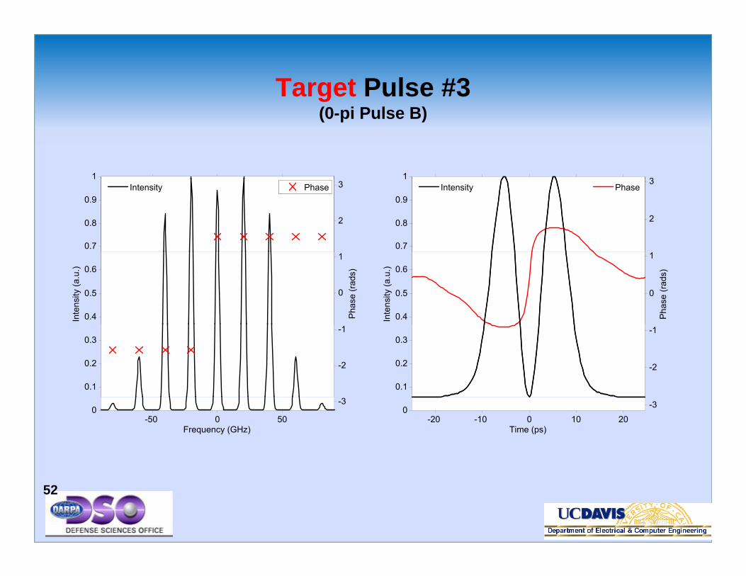
Target Pulse #3 ( )(0-pi Pulse B)
1 1 3
0.7
0.8
0.9Intensity
2
3Phase
0.7
0.8
0.9Intensity
2
3Phase
0.4
0.5
0.6
Inte
nsity
(a.u
.)
0
1
Pha
se (r
ads)
0.4
0.5
0.6
Inte
nsity
(a.u
.)
0
1
Pha
se (r
ads)
0.1
0.2
0.3
-2
-1
0.1
0.2
0.3
-2
-1
-50 0 500
Frequency (GHz)
-3
-20 -10 0 10 20
0
Time (ps)
-3
52
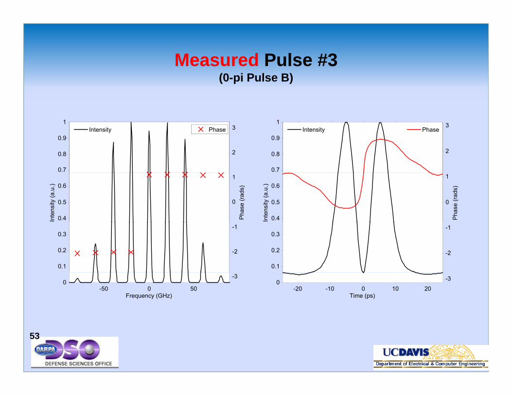
Measured Pulse #3( )(0-pi Pulse B)
1 1
0.7
0.8
0.9
1Intensity
2
3Phase
0.7
0.8
0.9
1Intensity
2
3Phase
0.4
0.5
0.6
Inte
nsity
(a.u
.)
0
1
Pha
se (r
ads)
0.4
0.5
0.6
Inte
nsity
(a.u
.)
0
1
Pha
se (r
ads)
0.1
0.2
0.3
-2
-1
0.1
0.2
0.3
-2
-1
-50 0 500
Frequency (GHz)
-3
-20 -10 0 10 20
0
Time (ps)
-3
53
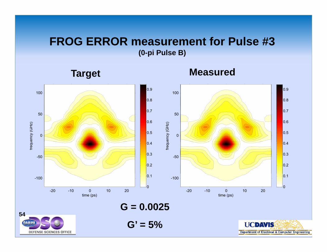
FROG ERROR measurement for Pulse #3 (0-pi Pulse B)
MeasuredTarget
100
0 7
0.8
0.9
100
0 7
0.8
0.9
g
uenc
y (G
Hz)
0
50
0 4
0.5
0.6
0.7
uenc
y (G
Hz)
0
50
0 4
0.5
0.6
0.7
frequ
-50
0.2
0.3
0.4
frequ
-50
0.2
0.3
0.4
time (ps)
-20 -10 0 10 20
-100
0
0.1
time (ps)
-20 -10 0 10 20
-100
0
0.1
G = 0 002554
G = 0.0025
G’ = 5%
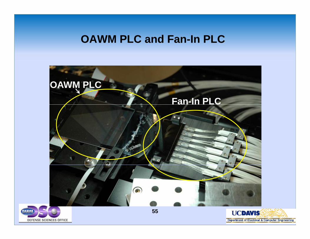
OAWM PLC and Fan-In PLC
OAWM PLC
Fan-In PLC
55