integrated high-t/sub c/ squid magnetometer
TRANSCRIPT
IEEE TWSACTIONS ON APPLIED SUPERCONDUCTIVITY, VOL. 5, NO. 2, JUNE 1995 2935
Integrated High-T, SQUID Magnetometer
Bernd David, Dirk Grundler*, Jens-Peter Knunme, and Olaf Doessel, Philips Research Laboratories, Department Technical Systems Hamburg, Roentgens&. 24-26, D-22335 Hamburg, Germany
*Institute of Applied Physics, University of Hamburg, JungiuSstr. 11, D-20355 Hambw, Germany
Abstract-We have fabricated an integrated SQUID magnetometer based on Y1Ba2Cu30, step-edge Josephson junctions. A tight coupling between the input coil and the SQUID washer has been achieved with a coupling coefficient k of 0.9. Noise measurements on our SQUIDS showed a nearly frequency independent flux noise of 50p" at 77K. llf-noise contributions at lower temperatures were always completely suppressed by bias reversal. From our measurements of the field sensitivity and the flux noise we can estimate a field resolution of the magnetometer of 60 fl" down to 1 Hz.
I. INTRODUCTION
There has been substantial progress in the sensitivity of magnetometers based on ~ a & u 3 0 7 W C O ) dc Super- conducting Quantum Interference Devices (dc SQUIDS) at 77 K. Although dc SQUIDs are very sensitive sensors for changes in magnetic flux, their effective pick-up area for external magnetic fields is extremely small due to their low inductance (typically 10-200 pH). The field resolution can be improved by an appropriate flux transforming input circuit (so-called flux antenna). Various configurations have been reported to increase the field resolution of dc SQUID magnetometers:
Tanaka et al. [ 11 attached a 11 mm x 11 mm flux concen- trating plate to the SQUID hole. They found for flux focusers of 1 1 mm x 1 1 mm a field resolution Bn of 200 fT/@ in the white noise region and of 3 7 O f f / G at 1OHz and 77 K.
Another flux transforming input circuit is realized by coupling a large area pickup loop directly to the SQUID inductance, as, for example, done by Koklle et al. [2]. Using YBCO bicrystal junction dc SQUIDS they found an excel- lent field resolution Bn of 93 ff/@ at 1Hz which is about the practical limit of this concept on 10 mm x 10 mm sub- strates. A better field resolution is expected for a multi-loop pickup coil directly coupled to the SQUID loop, as proposed by Drung and Koch [3].
In the classical coupling scheme a flux transformer con- sisting of a large area pick-up loop in series with a multi- turn planar input coil is inductively coupled to the SQUID inductance. One practical way is to fabricate and optimize the flux transformer and the SQUID on separate substrates. Only selected devices are mounted together in a flipchip arrangement [4], [5], [6], [7]. Although impressive results have been obtained, the small efficiency of coupling is a disadvantage of this concept. Manuscript received October 16,1994. This work was supported by the German Bundesministeriuni f i r Forschung und Technologie under contract number 13N5709 3.
A tight coupling is provided if the flux transformer is inte- grated monolithically with the SQUID on a single substrate. An integrated device was first reported by Lee et al. [SI, using template bi-epitaxial grain-boundary junctions and a total of nine layers, including three superconducting layers. With the same junction concept, Kromann et al. [9] used the SQUID washer as the return line of the input coil, thereby reducing the number of superconducting layers to two. The field sensitivity of the device was dominated by a l/f-noise contribution most likely arising from the motion of vortices in the upper film forming the input coil. Hilgenkamp et al. [lo] fabricated a four layer monolithic integrated high-Tc dc SQUID magnetometer based on bicrystal junctions. They measured an enhanced noise level attributed to LC- resonances caused by the parasitic capacitance between the input coil and the washer.
Up to now none of the published integrated magnetometers reached the field resolution of the flipchip or directly coupled devices, particularly in the low frequency range.
11. EXPERIMENTAL
Here we report on the fabrication of a monolithic inte- grated high-T, magnetometer using step-edge grain-bound- ary junctions. The process is based on our work on step-edge grain-boundary , dc SQUIDs [ l l ] and on our previously developed high-T, multi-layer technology [ 121 which has been successfully used for the fabrication of multi-turn flux transformers.
The device involves only two YBCO layers and two insu- lating SrTiO, (STO) layers. The films are prepared by off- axis rf-magnetron sputtering. Low-ohmic current and voltage contacts are achieved by an additional sputter deposited Ag layer.
A. Design rules
Based on our previous work we established some design rules for the integrated magnetometer conkpt: 1. In order to eliminate noise sources from imperfect films,
the SQUID washer and the pickup loop have to be fabricated from the bottom YBCO film which in general has better structural and superconducting properties than the top YBCO film.
2. Step-edge junctions degrade during successive high- temperature deposition steps. This implies that the junctions have to be formed from the top YBCO layer in the last deposition step. The superconducting contacts between the junctions and the SQUID washer have to be realized by largecurrent carrying "vias".
2936
3. The demand for fabricating the step-edge junctions from the top YBCO film requires that the stepedge forming the Josephson junctions is etched into a STO thin film instead of a STO single-crystalline substrate.
4. The washer acts as the return line of the input coil. 5. The input coil is patterned from the same top YBCO
layer as the stepedge junctions.
B. Fabrication process
The fabrication process involves the following seven deposition and photolithographic patterning steps: 1.
2.
3.
4.
5 .
6. 7.
The process starts with the in situ deposition of 150 nm YBCO covered by a 50 nm STO cap layer. The SQUID washer and the pickup loop are patterned From this bi-layer by pulsed Ar-ion-beam etching at a beam voltage of 350 V and an Ar-ion current density of 3 mA/cm2. Smooth edges are achieved by etching under flat incidence. Next, the substrate is covered by a 250 nm thick STO film. A steep step of 250 nm height, defining the grain-bound- ary, is etched into the STO film by Ar-ion beam etching under normal incidence using a photoresist mask. Using another photolithographic step, the contact windows are etched under flat incidence through both STO layers down into the YBCO bottom layer. 300 nm of YBCO are finally deposited. Prior to the etching of the top YBCO layer a Ag layer is sputter-deposited using a shadow mask technique. In a last patterning step the step-edge junctions and the input coil are formed.
C. Results
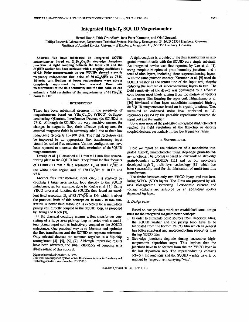
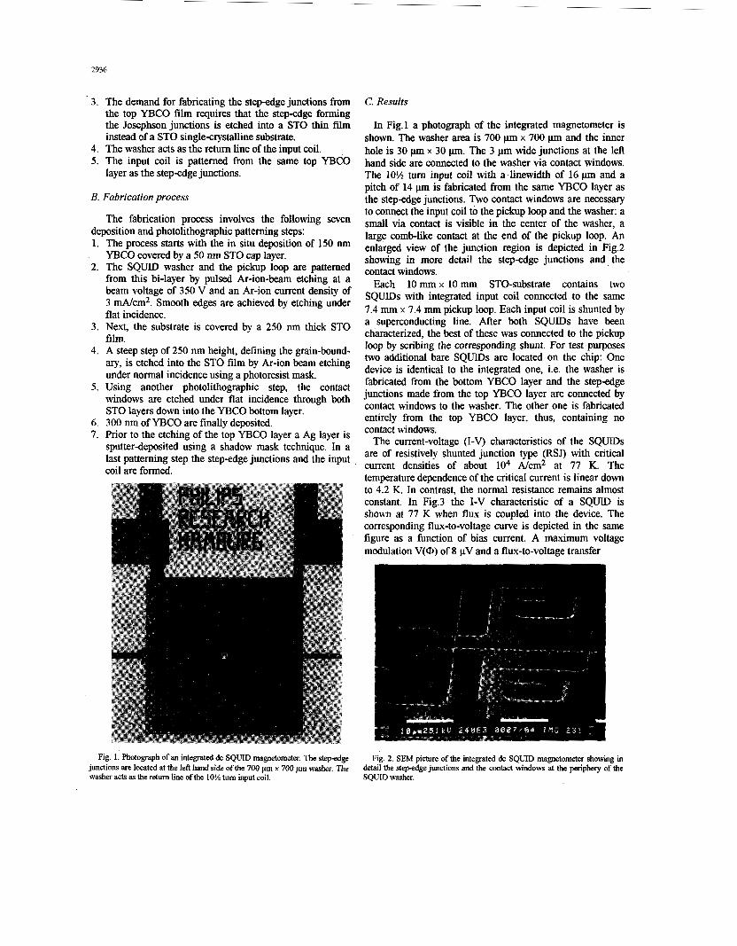
In Fig.1 a photograph of the integrated magnetometer is shown. The washer area is 700 p x 700 p and the inner hole is 30 pm x 30 p. The 3 pm wide junctions at the left hand side are connected to the washer via contact windows. The 10% turn input coil with a linewidth of 16 p and a pitch of 14 p is fabricated from the same YBCO layer as the stepedge junctions. Two contact windows are necessary to connect the input coil to the pickup loop and the washer: a small via contact is visible in the center of the washer, a large comb-like contact at the end of the pickup loop. An enlarged view of the junction region is depicted in Fig.2 showing in more detail the step-edge junctions and the contact windows.
Each 10 mm x 10 mm STO-substrate contains two SQUIDS with integrated input coil connected to the same 7.4 mm x 7.4 mm pickup loop. Each input coil is shunted by a superconducting line. After both SQUIDS have been characterized, the best of these was connected to the pickup loop by scribing the corresponding shunt. For test purposes two additional bare SQUIDS are located on the chip: One device is identical to the integrated one, i.e. the washer is fabricated from the bottom YBCO layer and the step-edge junctions made from the top YBCO layer are connected by contact windows to the washer. The other one is fabricated entirely from the top YBCO layer, thus, containing no contact windows.
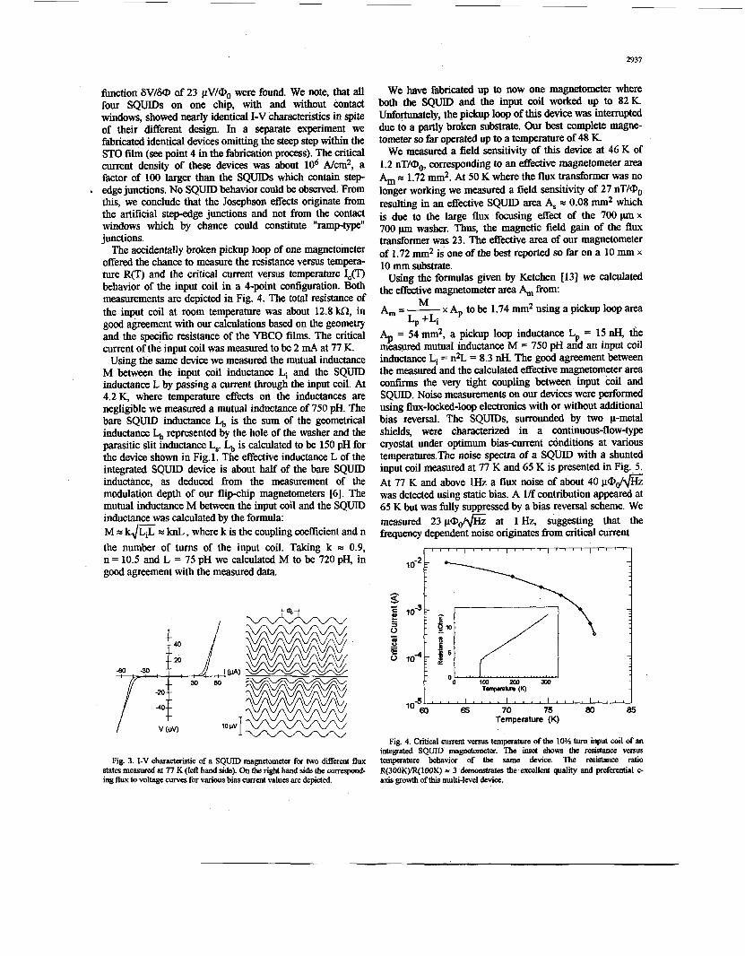
The current-voltage (I-v) characteristics of the SQUIDS are of resistively shunted junction type (RSJ) with critical current densities of about lo4 A/cm2 at 77 K. The temperature dependence of the critical current is linear down to 4.2 K. In contrast, the normal resistance remains almost constant. In Fig.3 the I-V characteristic of a SQUID is shown at 77 K when flux is coupled into the device. The corresponding flux-to-voltage curve is depicted in the same figure as a function of bias current. A maximum voltage modulation V(0) of 8 pV and a flux-to-voltage transfer
Fig. 1. Photograph of an integrated dc SQUID magnetometer. The step-edge junctions are located at the left hand si& of the 700 pm x 700 pm washer. The washer acts as the retum l i e ofthe 10% tum input coil.
Fig. 2. SEM picture of the integrated dc SQUID magnetometer showing h detail the step-edge junctions and the contact windows at the periphery of the SQUID washer.
2937
function 6V/&D of 23 pV/m0 were found. We note, that a l l four SQUIDS on one chip, with and without contact windows, showed nearly identical I-V characteristics in spite of their Werent design. In a separate experiment we fabricated identical devices omitting the steep step within the STO film (see point 4 in the fabrication process). The critical current density of these devices was about lo6 Nan2, a factor of 100 larger than the SQUIDS which contain step-
* edge junctions. No SQUID behavior could be observed. From this, we conclude that the Josephson effects originate from the artificial step-edge junctions and not from the contact windows which by chance could constitute "ramptype" junctions.
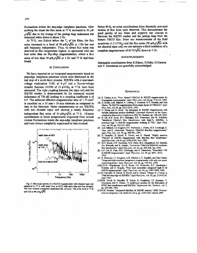
The accidentally broken pickup loop of one magnetometer offered the chance to measure the resistance versus tempera- ture R(T) and the critical current versus temperature Ic(T) behavior of the input coil in a 4-point configuration. Both measurements are depicted in Fig. 4. The total resistance of the input coil at room temperature was about 12.8kQ in good agreement with our calculations based on the geometry and the specific resistance of the YBCO films. The critical current of the input coil was measured to be 2 mA at 77 K.
Using the same device we measured the mutual inductance M between the input coil inductance Li and the SQUID inductance L by passing a current through the input coil. At 4.2% where temperature effects on the inductances are negligible we measured a mutual inductance of 750 pH. The bare SQUID inductance is the sum of the geometrical inductance L,, represented by the hole of the washer and the parasitic slit inductance L,. is calculated to be 150 pH for the device shown in Fig. 1. The effective inductance L of the integrated SQUID device is about half of the bare SQUID inductance, as deduced from the measurement of the modulation depth of our flip-chip magnetometers [6]. The mutual inductance M between the input coil and the SQUID inductance was calculated by the formula: M = k m = knL , where k is the coupling coefficient and n the number of turns of the input coil. Taking k = 0.9, n = 10.5 and L = 75 pH we calculated M to be 720 pH, in good agreement with the measured data.
10 pv
We have fabricated up to now one magnetometer where both the SQUID and the input coil worked up to 82K. Unfortunately, the pickup loop of this device was interrupted due to a partly broken substrate. Our best complete magne- tometer so far operated up to a temperature of 48 K.
We measured a field sensitivity of this device at 46 K of 1.2 nT/Oo, corresponding to an effective magnetometer area Am = 1.72 mm2. At 50 K where the flux transformer was no longer working we measured a field sensitivity of 27 nT/Oo resulting in an effective SQUID area A, m 0.08 mm2 which is due to the large flux focusing effect of the 700 pm x 700 p washer. Thus, the magnetic field gain of the flux transformer was 23. The effective area of our magnetometer of 1.72 mm2 is one of the best reported so far on a 10 mm x 10 mm substrate.
Using the formulas given by Ketchen [13] we calculated the effective magnetometer area A,,, from:
Am=- x A, to be 1.74 mm2 using a pickup loop area
A = 54 mm2, a pickup loop inductance Lp = 15 nH, the measured mutual inductance M = 750 pH and an input coil inductance Li = n2L = 8.3 nH. The good agreement between the measured and the calculated effective magnetometer area confirms the very tight coupling between input coil and SQUID. Noise measurements on our devices were performed using flux-locked-loop electronics with or without additional bias reversal. The SQUIDS, surrounded by two p-metal shields, were characterized in a continuous-flow-type cryostat under optimum biascurrent &nditions at various temperatures.The noise spectra of a SQUID with a shunted input coil measured at 77 K and 65 K is presented in Fig.. 5. At 77 K and above 1Hz a flux noise of about 40 pa& was detected using static bias. A l/f contribution appeared at 65 K but was fully suppressed by a bias reversal scheme. We measured 23 pod* at 1 Hz, suggesting that the frequency dependent noise originates from critical m n t
t " " I " " I " " I " " I " " I
L, +Li
P
65 70 75 80 85 Temperature (K)
Fig. 3. I-V characteristic of a SQUID magnetometer for two difEkrent flux states measured at 77 K (lefl hand side). On the ria hand side the compand- ing flux to voltage curves for various bias current values are depicted.
Fig. 4. Critical current versus temperature of the 10% turn k u t coil of an integrated SQUID magnetometer. The inset shows the resistance versus temperature behavior of the same device. The resistance ratio R(300K)IR(100K) * 3 demonstrates the excellent quality and preferential c- axis growth ofthis multi-level device.
2938
fluctuations within the stepedge Josephson junctions. After scribing the shunt the flux noise at 77 K increased to 50 pa fi due to the change of the pickup loop inductance but remained white down to about 1 Hz.
At 79K, two Kelvin below the Tc of the films, the flux noise increased to a level of 90 pa& at 1 Hz but was still frequency independent. Thus, no direct flux noise was observed in this temperature regime, in agreement with our best noise data on flipchip magnetometers, where a flux noise of less than 30 pa& at 1 Hz and 77 K had been found.
111. CONCLUSIONS
We have reported on an integrated magnetometer based on step-edge Josephson junctions which were fabricated in the last step of a multi-layer process. SQUIDS with a maximum voltage modulation V(@) of 8 pV and a flux-to-voltage transfer function 6V/6@ of 23 pV/@o at 77 K have been nleasured. The tight coupling between the input coil and the SQUID washer is demonstrated by the measured mutual inductance of 750 pH leading to a coupling coefficient k of 0.9. The achieved effective magnetometer area of 1.72 mm2 is excellent on a 10 mm x 10 mm substrate as compared to data in the literature. Noise measurements on our SQUDs with not shunted input coil showed a nearly fresuency independent flux noise of 50 pad$% at 77 K. l/f-noise contributions at lower temperatures originated from critical current fluctuations inside the stepedge Josephson junctions and were always completely suppressed by bias reversal.
-
77K -
65K -
10-51 , , , , , , , , I , , , , , , , , I , , , , , , , , , , , , , , , , , , , j 1 10 loo lo00
Frequency (Hz)
Fig. 5. Flux noise spectra of a SQUID magnetometer with shunted input coil measured at 77 K with static bias, at 65 K with static bias and bias reversal. The bias reversal completely suppresses the l/f-noise. The noise level at 77 K and 1Hz is 40 p@dG
Below 80 K, no noise contributions from thermally activated motion of flux lines were observed. This demonstrates the good quality of our films and supports our concept to fabricate the SQUID washer and the pickup loop from the bottom YBCO film. From our measurements of the field sensitivity (1.2 nT/Q0) and the flux noise (50 p@@ with not shunted input coil) we can estimate a field resolution of a complete magnetometer of 60 f f / f i down to 1 Hz.
ACKNOWLEDGMENT
Substantial contributions from REckart, G.Rabe, G.Kiirsten and V. Doormann are gratefully acknowledged.
111
121
[31
[41
REFERENCES
S. Tanaka et al., "Four channel YBaCuO dc SQUID magnetometer for biOmagneticmeasuremeub,"Appl. Phys.Len.,vol. 64,pp. 514516,1994. D. Koelle, AH. Miklich, F. Ludwig, E. Dantskef, D.T. Nemeth, and John Clarke, "dc SQUID m a g " e t e r s h m single layers of YBahO," Appl. Php. Len., vol. 63, pp. 2271-2273, 1993. D. Drung snd H. Koch, "An integrated dc SQUID Magnetometer with variable additional positive f + r &tended Abstracts of the Super- conductive Electronics Coverence ISEC'93, Boulder, pp. 128-129,1993 B. Oh, RH. Koch, W.J. Gallagher, RP. Robertazzi, and W. Eidelloth, "Multilevel YBaCuO flux transformers with high-Tc SQUIDS: A prototype high Tc SQUID magnetometer working at 779" Appl. Phys.
AH. Miklich, J. J. Kin@n, F.C. Wellstood, J. Clarke, M.S. Colclough, K. Char, and G. Zaharchdc, "Sensitive YBaCuO thin-film magnetometer:
D. Grundler, B. David, R. &kart, and 0. Wssel, "Highly sensitive
ApplPhys.Lett., vol. 63, pp. 2700-2702, Nov. 1993. M.N. Keene, S.W. Goodyear, N.G. Chew, RG. Humphrey% J.S. Satchell, J.A Edwards, and K. Lander, "Low-noise YBaCuO-F'rBahO multiturn flux transformers," Appwhysbn. , vol. 64, pp. 366-368, Jan. 1994. LP. Lee, K. Char, M.S. Colclough, and G. Zaharchuk, "Monolithic 77K dc SQUID magnetometer," Appl. Phys.Len., vol. 59, pp. 3051- 3053, 1991. R. Kromann, J.J. Kingston, AH. Miklich, L.T. Sagdahl, and John Clarke, "Integrated high-transition temperature magnetometer with only two super- conducting lavers."Aml. PhvsLett.. vol. 63, m. 559-561, 1993.
Le t t . ,~~l . 59, pp. 123-125, 1991.
A&. Phys. Lett., vol. 59, pp. 988-991, 1991.
YBaCuO dc SQUID -dometer with thh-film flux tranFforme,"
[10]J.W.M. I&&ku&'G.C.S. Brons, J.G. S&levilla, R.P. IJsselsteijn,J. Flokstra, and H. Rogalla, "Four layer monolithic integrated high-Tc dc SQUID magnetometer," Appl Phys.Len., vol. 64, pp. 3497-3499, 1994.
[11]D. Grundler, R &kart, B. David, and 0. D&sel, "Origin of l/f noise in YBaCuO step-edge dc SQUIDS," AppLPhysLen., vol. 62, pp. 2 134-2 136, April 1993.
[12]B.R. David, D. Grundler, R. &kart, K. Fan-el, J.P. Krumme, V. Door", and 0. D(rssel, "A multi-layer process for the fabrication of HTSC flux transformers and SQUIDS," Supercond. Sci. Technol., vol. 7,
[13]M.B. Ketchen, "Integrated thin-film dc SQUID semors," IEEE Transac- tions onhfagnetics, vol. MAG-23, No.2, pp. 1650-1657, March 1987.
p ~ . 287-289,1994.