integrated design and analysis of diamond-coated … · integrated design and analysis of...
TRANSCRIPT
Computer-Aided Design & Applications, 6(2), 2009, 195-205
195
Computer-Aided Design and Applications© 2009 CAD Solutions, LLC
http://www.cadanda.com
Integrated Design and Analysis of Diamond-coated Drills
Chao Miao1, Feng Qin2, Greg Sthur3, Kevin Chou4 and Raymond Thompson5
1The University of Alabama, [email protected] University of Alabama, [email protected]
3The University of Alabama, [email protected] University of Alabama, [email protected]
5Vista Engineering, Inc., [email protected]
ABSTRACT
The objective of this paper is to investigate the drill geometry effects on thedeposition residual stresses in diamond coated carbide drills, especially the interfacestresses. The approaches include (1) solid modeling of diamond-coated two-flute twistdrills using commercial computer-aided design (CAD) software, and (2) finite elementanalysis (FEA) to simulate residual stresses in a diamond-coated drill, which aregenerated during the deposition process due to the mismatched thermal expansioncoefficients. It is noted that the residual stresses generated by deposition in diamond-coated drills can be significant, on the order of GPa. The modeling methodology isemployed to design drills of different geometries. Further, to compare interfacestresses around the cutting edge, 2D FEA is applied to simulate residual stresses of thedrill cross-sections and the interface stress data at the drill cutting edge istransformed to quantitatively evaluate the drill geometry effects. The major results aresummarized as follows. (1) The micro-level geometry such as the edge radius has themost dominant effects on the interface stresses by the deposition. (2) In particular, theradial normal stresses can become largely tensile, over 1.0 GPa, which may affect thecoating adhesion integrity. (3) Changing the macro-level geometry such as the helixangle, point angle, and web-thickness will affect the wedge angle, 10o to 20o
differences, at the drill tip. However, the effects on the interface stress magnitudes arerather minor.
Keywords: deposition stress, diamond coating, FEA, twist drills.DOI:10.3722/cadaps.2009.195-205
1. INTRODUCTIONDrilling is among the most difficult machining processes because of chip-flow restrictions, poor heatdissipation, and rapid wear, which severely limits the productivity. Drilling constitutes about 40% of allmetal-cutting operations [9], and 50 to 70% of all production time is spent on making holes [1].Twistdrills used for hole making probably have one of the most complex shapes in machining tooling. Astandard two-flute twist drill has a configuration shown below, Fig. 1(a), which includes spiral flutesrunning along a cylindrical body and the point (drill tip) area. For the drill geometry study, it can bedated back to the mid-20th century. Several research groups developed drill models to formulatemathematical equations that describe the drill geometry, some relying on computer software togenerate the drill model. Galloway [7] initiated the drill geometry study with the focus on the drillingprocess mechanics, by which the author developed analytical equations relating the point shape of a
Computer-Aided Design & Applications, 6(2), 2009, 195-205
196
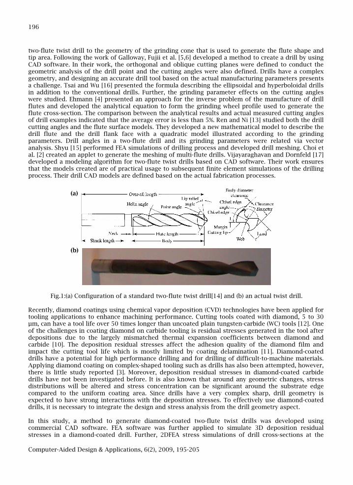
two-flute twist drill to the geometry of the grinding cone that is used to generate the flute shape andtip area. Following the work of Galloway, Fujii et al. [5,6] developed a method to create a drill by usingCAD software. In their work, the orthogonal and oblique cutting planes were defined to conduct thegeometric analysis of the drill point and the cutting angles were also defined. Drills have a complexgeometry, and designing an accurate drill tool based on the actual manufacturing parameters presentsa challenge. Tsai and Wu [16] presented the formula describing the ellipsoidal and hyperboloidal drillsin addition to the conventional drills. Further, the grinding parameter effects on the cutting angleswere studied. Ehmann [4] presented an approach for the inverse problem of the manufacture of drillflutes and developed the analytical equation to form the grinding wheel profile used to generate theflute cross-section. The comparison between the analytical results and actual measured cutting anglesof drill examples indicated that the average error is less than 5%. Ren and Ni [13] studied both the drillcutting angles and the flute surface models. They developed a new mathematical model to describe thedrill flute and the drill flank face with a quadratic model illustrated according to the grindingparameters. Drill angles in a two-flute drill and its grinding parameters were related via vectoranalysis. Shyu [15] performed FEA simulations of drilling process and developed drill meshing. Choi etal. [2] created an applet to generate the meshing of multi-flute drills. Vijayaraghavan and Dornfeld [17]developed a modeling algorithm for two-flute twist drills based on CAD software. Their work ensuresthat the models created are of practical usage to subsequent finite element simulations of the drillingprocess. Their drill CAD models are defined based on the actual fabrication processes.
Fig.1:(a) Configuration of a standard two-flute twist drill[14] and (b) an actual twist drill.
Recently, diamond coatings using chemical vapor deposition (CVD) technologies have been applied fortooling applications to enhance machining performance. Cutting tools coated with diamond, 5 to 30µm, can have a tool life over 50 times longer than uncoated plain tungsten-carbide (WC) tools [12]. Oneof the challenges in coating diamond on carbide tooling is residual stresses generated in the tool afterdepositions due to the largely mismatched thermal expansion coefficients between diamond andcarbide [10]. The deposition residual stresses affect the adhesion quality of the diamond film andimpact the cutting tool life which is mostly limited by coating delamination [11]. Diamond-coateddrills have a potential for high performance drilling and for drilling of difficult-to-machine materials.Applying diamond coating on complex-shaped tooling such as drills has also been attempted, however,there is little study reported [3]. Moreover, deposition residual stresses in diamond-coated carbidedrills have not been investigated before. It is also known that around any geometric changes, stressdistributions will be altered and stress concentration can be significant around the substrate edgecompared to the uniform coating area. Since drills have a very complex sharp, drill geometry isexpected to have strong interactions with the deposition stresses. To effectively use diamond-coateddrills, it is necessary to integrate the design and stress analysis from the drill geometry aspect.
In this study, a method to generate diamond-coated two-flute twist drills was developed usingcommercial CAD software. FEA software was further applied to simulate 3D deposition residualstresses in a diamond-coated drill. Further, 2DFEA stress simulations of drill cross-sections at the
(a)
(b)
Computer-Aided Design & Applications, 6(2), 2009, 195-205
197
cutting edge, at different locations, were approximated to obtain stress distributions around thecutting edge which can be extracted and transformed to quantitatively evaluate local interface stressesof different components. The solid modeling methodology was also employed to develop drill modelswith different geometry parameters such as the helix angle, point angle, and web thickness, and themodels were further used for 2D residual stress simulations. Therefore, drill geometry effectsincluding the cutting edge radius on the deposition stresses were quantified.
2. SOLID MODELING OF 3D DIAMOND-COATED TWO-FLUTE TWIST DRILLSSolid modeling of a twist drill consists of several procedures. With Solidworks used in this study, first,a helix curve with a specified helix angle (later serving as the sweep trajectory) is defined. Then, thespline curve of the flute cross-section is constructed according to the mathematical representation ofspecific drill geometry [17]. Once the flute cross-section (spline as well as the circular portion) iscompleted, the sweeping function is used to create the drill flute body. Next, the left and right grindingcones are defined mimicking the fabrication process that generates the drill tip: two cutting lips and achisel edge. Finally, an edge radius is incorporated along the cutting lips and chisel edge.
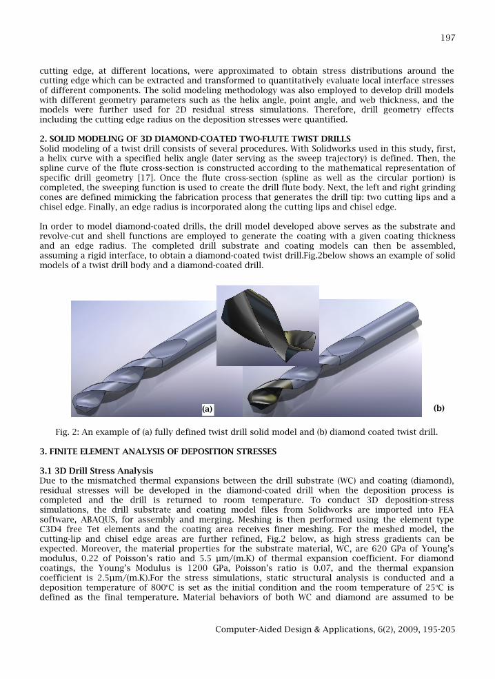
In order to model diamond-coated drills, the drill model developed above serves as the substrate andrevolve-cut and shell functions are employed to generate the coating with a given coating thicknessand an edge radius. The completed drill substrate and coating models can then be assembled,assuming a rigid interface, to obtain a diamond-coated twist drill.Fig.2below shows an example of solidmodels of a twist drill body and a diamond-coated drill.
Fig. 2: An example of (a) fully defined twist drill solid model and (b) diamond coated twist drill.
3. FINITE ELEMENT ANALYSIS OF DEPOSITION STRESSES
3.1 3D Drill Stress AnalysisDue to the mismatched thermal expansions between the drill substrate (WC) and coating (diamond),residual stresses will be developed in the diamond-coated drill when the deposition process iscompleted and the drill is returned to room temperature. To conduct 3D deposition-stresssimulations, the drill substrate and coating model files from Solidworks are imported into FEAsoftware, ABAQUS, for assembly and merging. Meshing is then performed using the element typeC3D4 free Tet elements and the coating area receives finer meshing. For the meshed model, thecutting-lip and chisel edge areas are further refined, Fig.2 below, as high stress gradients can beexpected. Moreover, the material properties for the substrate material, WC, are 620 GPa of Young’smodulus, 0.22 of Poisson’s ratio and 5.5 µm/(m.K) of thermal expansion coefficient. For diamondcoatings, the Young’s Modulus is 1200 GPa, Poisson’s ratio is 0.07, and the thermal expansioncoefficient is 2.5µm/(m.K).For the stress simulations, static structural analysis is conducted and adeposition temperature of 800oC is set as the initial condition and the room temperature of 25oC isdefined as the final temperature. Material behaviors of both WC and diamond are assumed to be
(a) (b)
Computer-Aided Design & Applications, 6(2), 2009, 195-205
198
elastic due to their high melting points and brittleness. Thus, the coating-substrate interface wasconsidered to be rigid. The boundary condition includes a fully constrained surface at the drill bottom.
Fig.3: Element meshing for diamond-coated drill stress simulations: (a) the entire drill model and (b)around drill tip.
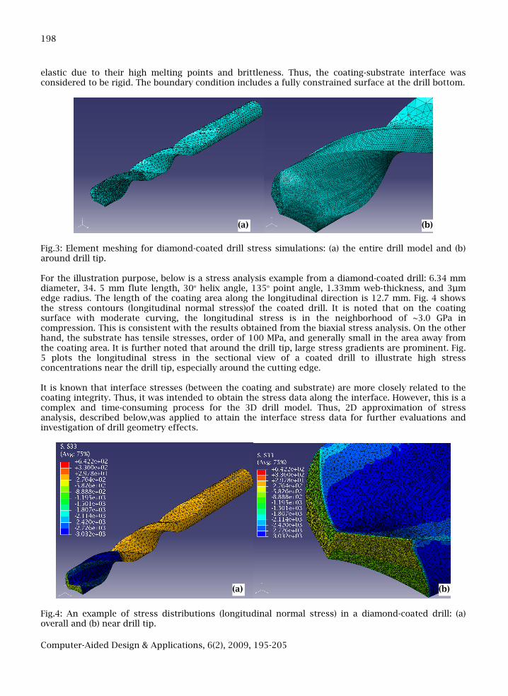
For the illustration purpose, below is a stress analysis example from a diamond-coated drill: 6.34 mmdiameter, 34. 5 mm flute length, 30o helix angle, 135o point angle, 1.33mm web-thickness, and 3µmedge radius. The length of the coating area along the longitudinal direction is 12.7 mm. Fig. 4 showsthe stress contours (longitudinal normal stress)of the coated drill. It is noted that on the coatingsurface with moderate curving, the longitudinal stress is in the neighborhood of ~3.0 GPa incompression. This is consistent with the results obtained from the biaxial stress analysis. On the otherhand, the substrate has tensile stresses, order of 100 MPa, and generally small in the area away fromthe coating area. It is further noted that around the drill tip, large stress gradients are prominent. Fig.5 plots the longitudinal stress in the sectional view of a coated drill to illustrate high stressconcentrations near the drill tip, especially around the cutting edge.
It is known that interface stresses (between the coating and substrate) are more closely related to thecoating integrity. Thus, it was intended to obtain the stress data along the interface. However, this is acomplex and time-consuming process for the 3D drill model. Thus, 2D approximation of stressanalysis, described below,was applied to attain the interface stress data for further evaluations andinvestigation of drill geometry effects.
Fig.4: An example of stress distributions (longitudinal normal stress) in a diamond-coated drill: (a)overall and (b) near drill tip.
(a) (b)
(a) (b)
Computer-Aided Design & Applications, 6(2), 2009, 195-205
199
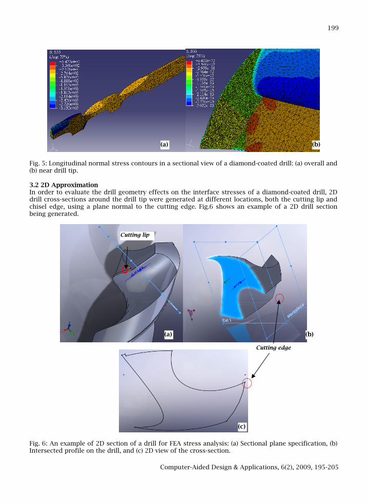
Fig. 5: Longitudinal normal stress contours in a sectional view of a diamond-coated drill: (a) overall and(b) near drill tip.
3.2 2D ApproximationIn order to evaluate the drill geometry effects on the interface stresses of a diamond-coated drill, 2Ddrill cross-sections around the drill tip were generated at different locations, both the cutting lip andchisel edge, using a plane normal to the cutting edge. Fig.6 shows an example of a 2D drill sectionbeing generated.
Fig. 6: An example of 2D section of a drill for FEA stress analysis: (a) Sectional plane specification, (b)Intersected profile on the drill, and (c) 2D view of the cross-section.
(a) (b)
(a) (b)
(c)
Cutting lip
Cutting edge
Computer-Aided Design & Applications, 6(2), 2009, 195-205
200
Considering the relative motion at the local drill edge (i.e., rotation, as in actual drill operation), aworkpiece plane can be defined, Fig.6(b), to evaluate the cutting geometry such as the rake angle. Asseen from the Fig.6(b), the highlighted area is the cross-section and the two planes represent thesectional plane and workpiece plane. In this particular cross-section, which is about 1 mm away fromthe outer diameter, the rake and relief angles are 30.11o and 5.8o, respectively. The cross-sectionprofile can then be extracted and exported to ABAQUS. With addition of a specified edge radius and acoating layer, uniformly all around, 2D FEA simulations of deposition stresses is conducted, with anassumption of 2D plane strain. The material properties and the deposition temperature are the sameas in the 3D analysis. The boundary conditions applied include one fully constraint corner (away fromthe cutting edge) and another partially constrained (one direction) point.
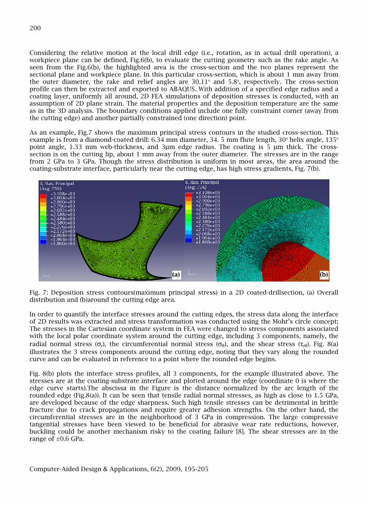
As an example, Fig.7 shows the maximum principal stress contours in the studied cross-section. Thisexample is from a diamond-coated drill: 6.34 mm diameter, 34. 5 mm flute length, 30o helix angle, 135o
point angle, 1.33 mm web-thickness, and 3µm edge radius. The coating is 5 µm thick. The cross-section is on the cutting lip, about 1 mm away from the outer diameter. The stresses are in the rangefrom 2 GPa to 3 GPa. Though the stress distribution is uniform in most areas, the area around thecoating-substrate interface, particularly near the cutting edge, has high stress gradients, Fig. 7(b).
Fig. 7: Deposition stress contours(maximum principal stress) in a 2D coated-drillsection, (a) Overalldistribution and (b)around the cutting edge area.
In order to quantify the interface stresses around the cutting edges, the stress data along the interfaceof 2D results was extracted and stress transformation was conducted using the Mohr’s circle concept;The stresses in the Cartesian coordinate system in FEA were changed to stress components associatedwith the local polar coordinate system around the cutting edge, including 3 components, namely, the
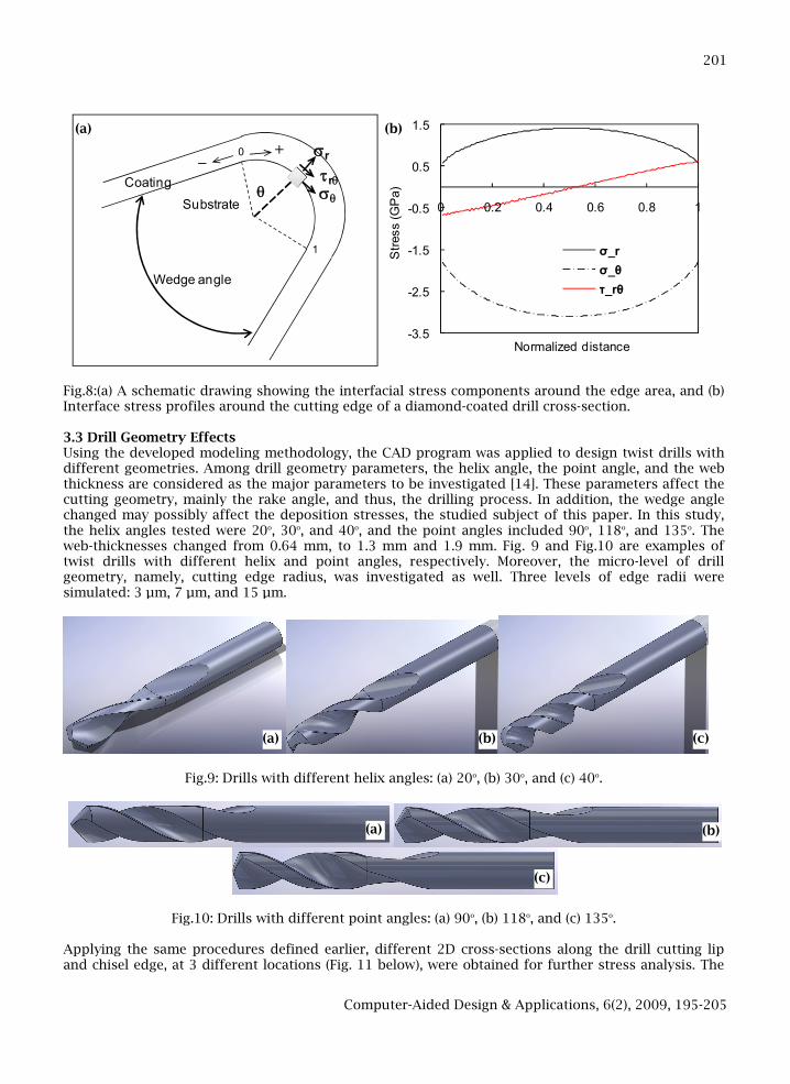
radial normal stress (σr), the circumferential normal stress (σθ), and the shear stress (τrθ). Fig. 8(a)
illustrates the 3 stress components around the cutting edge, noting that they vary along the roundedcurve and can be evaluated in reference to a point where the rounded edge begins.
Fig. 8(b) plots the interface stress profiles, all 3 components, for the example illustrated above. Thestresses are at the coating-substrate interface and plotted around the edge (coordinate 0 is where theedge curve starts).The abscissa in the Figure is the distance normalized by the arc length of therounded edge (Fig.8(a)). It can be seen that tensile radial normal stresses, as high as close to 1.5 GPa,are developed because of the edge sharpness. Such high tensile stresses can be detrimental in brittlefracture due to crack propagations and require greater adhesion strengths. On the other hand, thecircumferential stresses are in the neighborhood of 3 GPa in compression. The large compressivetangential stresses have been viewed to be beneficial for abrasive wear rate reductions, however,buckling could be another mechanism risky to the coating failure [8]. The shear stresses are in therange of ±0.6 GPa.
(a) (b)
Computer-Aided Design & Applications, 6(2), 2009, 195-205
201
Coating
Substrate
sr
q
+
sq
1
trq
0_
Wedge angle
-3.5
-2.5
-1.5
-0.5
0.5
1.5
0 0.2 0.4 0.6 0.8 1
Str
ess
(GP
a)
Normalized distance
σ_r
σ_θ
τ_rθ
Fig.8:(a) A schematic drawing showing the interfacial stress components around the edge area, and (b)Interface stress profiles around the cutting edge of a diamond-coated drill cross-section.
3.3 Drill Geometry EffectsUsing the developed modeling methodology, the CAD program was applied to design twist drills withdifferent geometries. Among drill geometry parameters, the helix angle, the point angle, and the webthickness are considered as the major parameters to be investigated [14]. These parameters affect thecutting geometry, mainly the rake angle, and thus, the drilling process. In addition, the wedge anglechanged may possibly affect the deposition stresses, the studied subject of this paper. In this study,the helix angles tested were 20o, 30o, and 40o, and the point angles included 90o, 118o, and 135o. Theweb-thicknesses changed from 0.64 mm, to 1.3 mm and 1.9 mm. Fig. 9 and Fig.10 are examples oftwist drills with different helix and point angles, respectively. Moreover, the micro-level of drillgeometry, namely, cutting edge radius, was investigated as well. Three levels of edge radii weresimulated: 3 µm, 7 µm, and 15 µm.
Fig.9: Drills with different helix angles: (a) 20o, (b) 30o, and (c) 40o.
Fig.10: Drills with different point angles: (a) 90o, (b) 118o, and (c) 135o.
Applying the same procedures defined earlier, different 2D cross-sections along the drill cutting lipand chisel edge, at 3 different locations (Fig. 11 below), were obtained for further stress analysis. The
(a) (b) (c)
(a) (b)
(c)
(a) (b)
Computer-Aided Design & Applications, 6(2), 2009, 195-205
202
wedge angle of each section was also evaluated and compared between different types of drills. Tab.1below lists the wedge angles a different cross-sections of drills with different helix and point angles.
Pointangle (o)
Sec.1 Sec. 2 Chisel Sec. Helixangle(o)
Sec.1 Sec.2 Chisel Sec.
90 47 53 90 20 65 68 113
118 54 59 114 30 54 59 113
135 57 61 129 40 43 49 113
Tab. 1: Wedge angle (o) at different sections of drills with different point and helix angles.
Fig. 11: Locations of different drill cross-sections analyzed in Tab. 1.
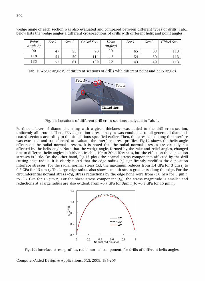
Further, a layer of diamond coating with a given thickness was added to the drill cross-section,uniformly all around. Then, FEA deposition stress analysis was conducted to all generated diamond-coated sections according to the simulations specified earlier. Then, the stress data along the interfacewas extracted and transformed to evaluate the interface stress profiles. Fig.12 shows the helix angleeffects on the radial normal stresses. It is noted that the radial normal stresses are virtually notaffected by the helix angle. Note that the wedge angle, formed by the rake and relief angles, changeddue to different helix angles is fairly noticeable, 10o to 20o differences, but the effect on the depositionstresses is little. On the other hand, Fig.13 plots the normal stress components affected by the drillcutting edge radius. It is clearly noted that the edge radius (r
e) significantly modifies the deposition
interface stresses. For the radial normal stress (σr), the maximum reduces from 1.4 GPa for 3 µm re
to
0.7 GPa for 15 µm re. The large edge radius also shows smooth stress gradients along the edge. For the
circumferential normal stress (σθ), stress reductions by the edge hone were from -3.0 GPa for 3 µm re
to -2.7 GPa for 15 µm re. For the shear stress component (τrθ), the stress magnitude is smaller and
reductions at a large radius are also evident: from ~0.7 GPa for 3µm reto ~0.3 GPa for 15 µm r
e.
0.5
0.7
0.9
1.1
1.3
0 0.2 0.4 0.6 0.8 1
sr(G
Pa)
Normalized distance
20°
30°
40°
Fig. 12: Interface stress profiles, radial normal component, for drills of different helix angles.
Sec. 1
Sec. 2
Chisel Sec.
Computer-Aided Design & Applications, 6(2), 2009, 195-205
203
0
0.5
1
1.5
0 0.2 0.4 0.6 0.8 1
sr(G
Pa)
Normalized distance
3 µm
7 µm
15 µm
-3.5
-3
-2.5
-2
-1.5
-1
-0.5
0
0.5
0 0.2 0.4 0.6 0.8 1
sq
(GP
a)
Normalized distance
3 µm
7 µm
15 µm
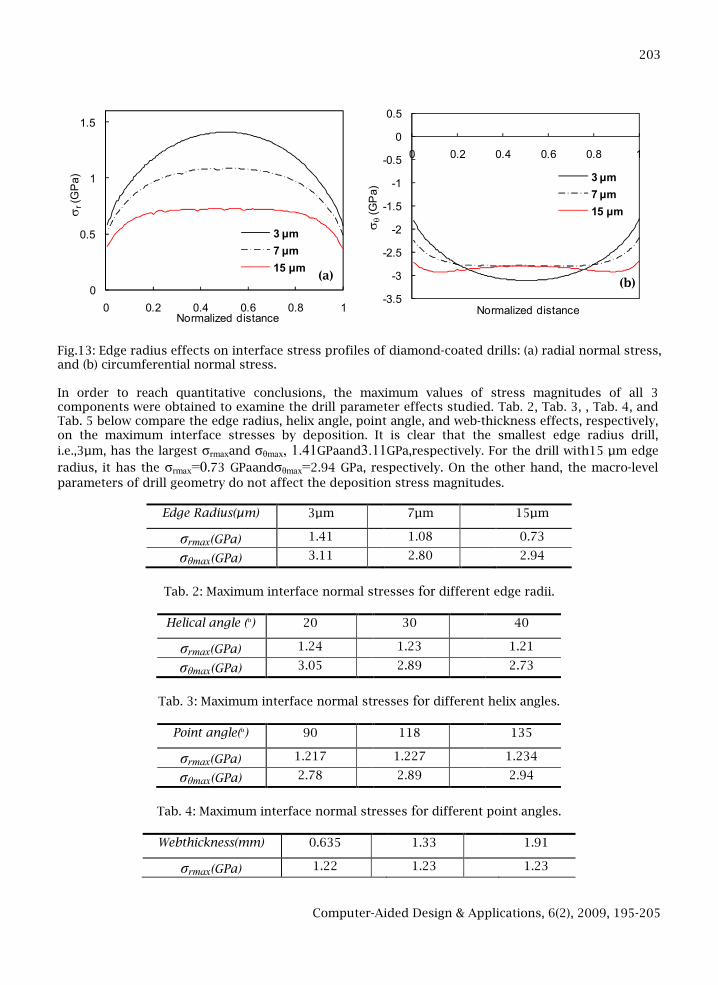
Fig.13: Edge radius effects on interface stress profiles of diamond-coated drills: (a) radial normal stress,and (b) circumferential normal stress.
In order to reach quantitative conclusions, the maximum values of stress magnitudes of all 3components were obtained to examine the drill parameter effects studied. Tab. 2, Tab. 3, , Tab. 4, andTab. 5 below compare the edge radius, helix angle, point angle, and web-thickness effects, respectively,on the maximum interface stresses by deposition. It is clear that the smallest edge radius drill,
i.e.,3µm, has the largest σrmaxand σθmax, 1.41GPaand3.11GPa,respectively. For the drill with15 µm edge
radius, it has the σrmax=0.73 GPaandσθmax=2.94 GPa, respectively. On the other hand, the macro-level
parameters of drill geometry do not affect the deposition stress magnitudes.
Edge Radius(µm) 3µm 7µm 15µm
σrmax(GPa) 1.41 1.08 0.73
σθmax(GPa) 3.11 2.80 2.94
Tab. 2: Maximum interface normal stresses for different edge radii.
Helical angle (o) 20 30 40
σrmax(GPa) 1.24 1.23 1.21
σθmax(GPa) 3.05 2.89 2.73
Tab. 3: Maximum interface normal stresses for different helix angles.
Point angle(o) 90 118 135
σrmax(GPa) 1.217 1.227 1.234
σθmax(GPa) 2.78 2.89 2.94
Tab. 4: Maximum interface normal stresses for different point angles.
Webthickness(mm) 0.635 1.33 1.91
σrmax(GPa) 1.22 1.23 1.23
(a)(b)
Computer-Aided Design & Applications, 6(2), 2009, 195-205
204
σθmax(GPa) 2.85 2.89 2.92
Tab. 5: Maximum interface normal stresses for different web thicknesses.
4. CONCLUSIONSSolid modeling of diamond-coated drills using CAD software has been achieved in this study. 3D FEAsimulations have been developed as well to study deposition residual stresses in a diamond coateddrill. The nominal longitudinal normal stresses in the area of less curvature are about 3 GPa incompression, which is consistent with the biaxial stress analysis. The model can be used to designdrills with different geometric parameters. Moreover, 2D approximation of FEA stress simulations isapplied to investigate drill geometry effects on interface stresses around the drill cutting edge. Theresidual stresses generated by deposition in the diamond-coated drills can be significant. The micro-level geometry such as the edge radius has the most dominant effects on the interface stresses. Inparticular, the radial normal stresses can become largely tensile, over 1.0 GPa, which may affect theadhesion integrity. Changing the macro-level geometry such as the helix angle, point angle, and web-thickness will affect the wedge angle, 10o to 20o differences, at the cutting tip. However, the effects onthe interface stress magnitudes are rather minor. For future work, the coating thickness effects on theinterface residual stresses in diamond coated drills will be incorporated. Moreover, during machining,the deposition residual stresses will be affected by the induced mechanical and thermal loads. Thus, itis necessary to concurrently investigate the stress field evolutions during drilling in order toeffectively use diamond coated drills.
5. ACKNOWLEDGEMENTSThe research is supported by NSF Grant No: IIP 0741028 and CMMI 0728228.
6. REFERENCES[1] Benes, J.: Hole Making Trends Run Deep, Fast, and Dry, American Machinist, (May 2000), 2000,
97–102.[2] Choi, J.; Min, S.; Dornfeld, D. A.; Alam, M.; Tzong, T.: Modelingof Inter-Layer Gap Formation in
Drilling of a Multilayered Material, Proc. Of6th CIRP International Workshop on Modeling ofMachining Operations, McMaster University, Hamilton, Canada, May 19–20, CIRP, Hamilton,Ontario,Canada, 2003, 113–118.
[3] Chen, M.; Jian, X.G.; Sun, F.H.; Hu, B.; Liu, X.S.: Development of diamond-coated drills and theircutting performance, Journal of Materials Processing Technology, 129, 2002, 81-85.
[4] Ehmann, K. F.: Grinding Wheel Profile Definition for the Manufactureof Drill Flutes, CIRP Ann.,39(1), 1990, 153–156.
[5] Fujii, S.; DeVries, M. F.; Wu, S. M.: An Analysis of Drill Geometryfor Optimum Drill Design byComputer — Part I: Drill Geometry Analysis, ASME J. Eng. Ind., 92, 1970, 647–656.
[6] Fujii, S.; DeVries, M. F.; Wu, S. M.: An Analysis of Drill Geometryfor Optimum Drill Design byComputer — Part II: Computer Aided Design, ASME J. Eng. Ind., 92, 1970, 657–666.
[7] Galloway, D. F.: Some Experiments on the Influence of Various Factors on Drill Performance,Trans. ASME, 79, 1957, 191–231.
[8] Gahlin, R.; Alahelisten, A.; Jacobson, S.: The effects of compressive stresses on theabrasion ofdiamond coatings wear, 196, 1996, 226-233.
[9] Hamade, R. F.; Ismail, F.: A Case for Aggressive Drilling of Aluminum, Journal of MaterialsProcessing Technology, 166, 2005, 86-97.
[10] Hu, J.; Chou, Y. K.; Thompson,R. G.: On Stress Analysis of Diamond Coating Cutting Tools,Transactions of NAMRI/SME, 35, 2007, 177-184.
[11] Hu, J.; Chou, Y. K.; Thompson, R. G.:A Numerical Study of Interface Behavior of Diamond CoatedCutting Tools, Transactions of NAMRI/SME, 36, 2008, 533-540.
[12] Oles, E. J.; Inspektor, A.; Bauer, C.E.: The New Diamond-coated Carbide Cutting Tools, Diamondand Related Materials, 5(6-8), 1996, 617-624.
[13] Ren, R.; Ni, J.: Analyses of Drill Flute and Cutting Angles, Int. J.Adv. Manuf. Technol., 15, 1999,546–553.
Computer-Aided Design & Applications, 6(2), 2009, 195-205
205
[14] Stephenson, D. A.; Agapiou, J. S.: Metal Cutting Theory and Practice, CRC, 1st edition, 1996, 205-218.
[15] Shyu, B.: Computer Simulations for Burr Formation Study, Ph.D. thesis, University of California,Berkeley.
[16] Tsai, W. D.; Wu, S. M.: Computer Analysis of Drill Point Geometry, International Journal ofMachine Tool Design and Research, 19(1), 1979, 95–108.
[17] Vijayaraghavan, A.; Dornfeld, D. A.: Automated Drill Modeling for Drilling Process Simulation,Journal of Computing and Information Science in Engineering, 7, 2004, 276–282.