integral bridge for high-speed railwayoa.upm.es/11242/2/inve_mem_2011_102837.pdf · integral bridge...
TRANSCRIPT
Integral Bridge for High-Speed Railway Javier Rodriguez, Principia; Francisco Martinez, Principia; Joaquin Marti, Principia; Velazquez, Madrid, Spain.
Abstract
The structural continuity of fully integral bridges entails many advantages and some drawbacks. Among the latter, the cyclic expansions and contractions of the deck caused by seasonal thermal variations impose alternating displacements at the piers and abutments, with effects that may be difficult to establish reliably. The advantages include easier construction and cheaper maintenance but, especially, horizontal loads can be transmitted to the ground in a much better way than in conventional bridges. This paper first presents a methodology for dealing with the problems that the cyclic displacements imposed raise at the abutments and at the bridge piers. At the former, large pressures may develop, possibly accompanied by undesirable surface settlements. At the latter, the degree of cracking and the ability to carry the specified loads may be in question. Having quantified the drawbacks, simplified but realistic analyses are conducted of the response of an integral bridge to braking and seismic loads. It is shown that integral bridges constitute an excellent alternative in the context of the requirements posed by new high-speed railway lines.
Keywords: jointless bridge; integral abutment; concrete pier; ductility.
Introduction
It could be said that for many centuries mankind built only integral bridges, although their reintroduction is less than a century old. The essential characteristic of an integral bridge is the absence of structural discontinuities, such as expansion joints and sliding supports. As a consequence, the expansions and contractions of the deck affect the abutments and piers; such effects are minimised in a conventional bridge.
On the other hand an integral design offers the advantages associated with structural monolithism: all piers and abutments can collaborate towards a distributed transmission of the horizontal loads to the ground; also, the redundancy of the structure produces a more desirable global response and contributes ductility to the potential failure modes. The ability to transmit large horizontal forces to the ground in an orderly manner is particularly significant in railway bridges, which must be designed to withstand considerable loads from the emergency braking of
trains, as well as those arising from seismic action. Apart from those advantages, the absence of joints and bearings makes construction easier and faster, and also results in maintenance savings.
Jointless highway bridges are relatively common in many parts of the world, with the United States accounting for at least 13 000 of them. In the United Kingdom bridge decks up to 60 m in length with skews below 30° are generally required to be continuous over intermediate supports and integral with their abutments.1 However, in spite of this wealth of experience, the design rules vary widely. A recent report2 gave the results of a survey sent to all the transportation agencies in the United States and Canada, which was answered by 34 in the United States and one in Canada: jointless bridges made of prestressed concrete have their dimensions limited to lengths ranging from 45,7 to 358 m, their skew angles from 15 to 70°, and their curvatures from 0° to no limit. The inevitable conclusion from such variety of criteria in a relatively close geographical environment is that there is only limited common understanding as to how integral bridges perform and what are the mechanisms that may eventually fail them.
In Spain the length of integral highway bridges is not specifically limited, but the horizontal displacements of the deck cannot exceed 30 mm, which in practice limits the length to about 100 m, even before accounting for shrinkage and creep.3 And there are also other limitations, like 60° on skew and a radius of curvature that must exceed ten times the deck width.
In spite of the relative scarcity of national criteria, and the at-times conflicting character of the existing ones, it is a fact that in recent years integral bridges have become increasingly popular in Europe.4-6
Abutment Behaviour
One of the difficult questions posed by integral bridges is the behaviour of the abutments, whether the ground is a compacted fill or a soil-cement mixture, and its interaction with the abutment wall. Indeed, apart from the effects of shrinkage and creep, seasonal temperature changes cause cyclic lengthening and shortening of the deck, which has both cyclic and cumulative effects on the soil-structure interaction that occurs at the abutments. The main concerns are that pressures developed between the abutment wall and a compacted fill may grow to values as high as eight times the vertical pressure and that undesirable surface settlements may also occur.
The above questions have been looked at by a number of investigators, both in laboratory experiments and in the field8. The results have been progressively incorporated in design guides and recommendations, but once again the published comparisons of their provisions regarding the passive earth pressure coefficients recommended for design, bear witness to a fair diversity of opinions.9-10
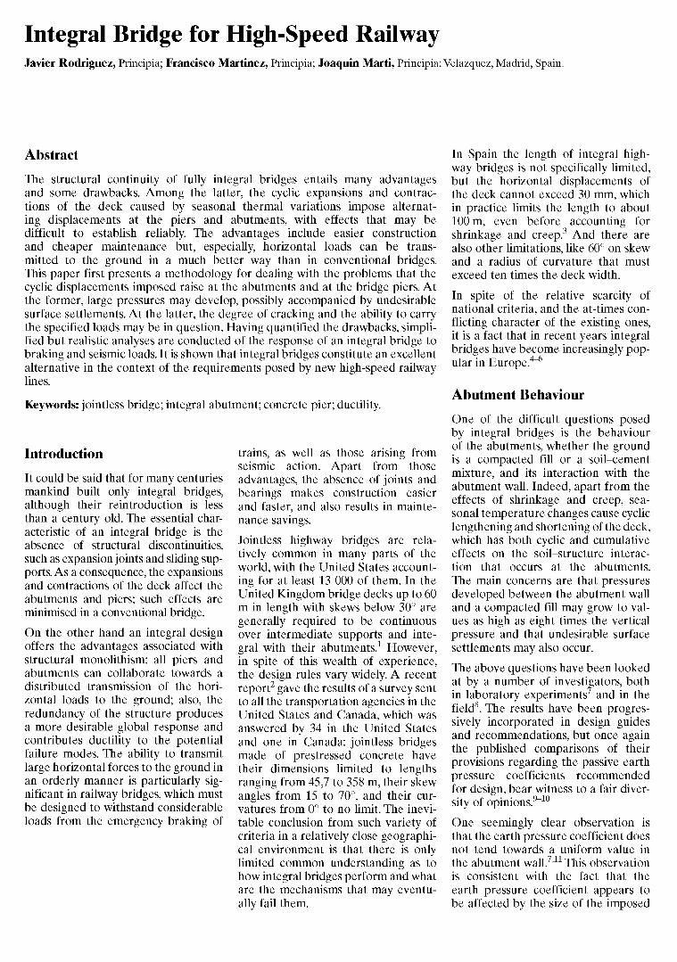
One seemingly clear observation is that the earth pressure coefficient does not tend towards a uniform value in the abutment wall.711 This observation is consistent with the fact that the earth pressure coefficient appears to be affected by the size of the imposed
1 2 3 4 5 6 7
Earth pressure coefficient (-)
Fig. 1: Pressure distributions for different wall rotations
Symmetry
Prevented longitudinal displacements
4,2 m 2,8 m
Prevented vertical displacements
displacements and the number of cycles. Indeed the coefficient initially increases with the number of cycles, but the relation tends to saturate and the value of the coefficient eventually stabilises. On the other hand, if the movements are small, the coefficient will not approach its maximum value of about 8 however large the number of cycles. As can be seen in Fig. 1, the simple hypothesis that the coefficient is proportional to the displacement up to a value of 8, leads to a reasonable approximation of the values reported7
for large numbers of cycles.
The evolution of wall pressures, linked to progressive compaction and arching effects in the backfill, has been studied12 and while useful insights have been provided into the compaction taking place. The related development of surface settlements also requires that the cyclic motions exceed a certain threshold.1314
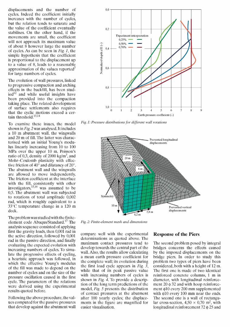
To examine these issues, the model shown in Fig. 2 was analysed. It includes a 10 m abutment wall, the wingwalls and 20 m of fill. The latter was characterised with an initial Young's modulus linearly increasing from 10 to 100 MPa over the upper 10 m, Poisson's ratio of 0,3, density of 2000 kg/m3, and Mohr-Coulomb plasticity with effective friction of 40° and dilatancy of 20°. The abutment wall and the wingwalls are allowed to move independently. The friction coefficient at the interface with the fill, consistently with other investigators,1516 was assumed to be 0,5. The abutment wall was subjected to rotations of total amplitude 0,002 rad, which is roughly equivalent to a 33°C temperature change in a 120 m deck.
The problem was studied with the finite-element code Abaqus/Standard.17 The analysis sequence consisted of applying first the gravity loads, then 0,001 rad in the active direction, followed by 0,001 rad in the passive direction, and finally evaluating the expected evolution with increasing numbers of cycles. To simulate the progressive effects of cycling, a heuristic approach was followed, in which the effective Young's modulus of the fill was made to depend on the number of cycles and on the size of the pressure oscillation caused in the first cycle. The parameters of the relations were derived using the experimental results quoted before.
Following the above procedure, the values computed for the passive pressures that develop against the abutment wall
0,0
Fig. 2: Finite-element mesh and dimensions
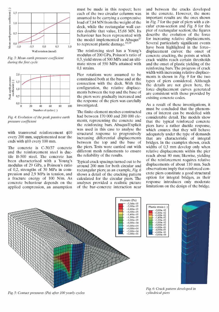
compare well with the experimental determinations as quoted above. The maximum contact pressures tend to develop towards the central part of the wall. Also, the results allow calculating a mean earth pressure coefficient for the complete wall; its evolution during the first load cycle appears in Fig. 3, while that of its peak passive value with increasing numbers of cycles is shown in Fig. 4. To provide a description of the long term predictions of the model, Fig. 5 presents the distribution of contact pressures at the abutment after 100 yearly cycles; the displacements in the figure are magnified for easier visualisation.
Response of the Piers
The second problem posed by integral bridges concerns the effects caused by the imposed displacements on the bridge piers. In order to study this problem two types of piers have been considered, both with a height of 12 m. The first one is made of two identical reinforced concrete columns, 1 m in diameter, with longitudinal reinforcement 20 § 32 and with hoop reinforcement (|>10 every 200 mm supplemented with (|)10 every 100 mm near the ends. The second one is a wall of rectangular cross-section, 4,50 x 0,70 m2, with longitudinal reinforcement 72 § 25 and
0,2
• | -1 ,0 -0 ,5 0,0 0,5 1,0
Wall rotation (mrad)
Fig. 3: Mean earth pressure coefficient during the first cycle
20 40 60 80 100
Number of cycles (-)
Fig. 4: Evolution of the peak passive earth pressure coefficient
with transversal reinforcement $10 every 200 mm, supplemented near the ends with $10 every 100 mm.
The concrete is C-30/37 concrete and the reinforcement steel is ductile B-500 steel. The concrete has been characterised with a Young's modulus of 29 GPa, a Poisson's ratio of 0,2, strengths of 30 MPa in compression and 2,9 MPa in tension, and a fracture energy of 100 N/m. As concrete behaviour depends on the applied compression, an assumption
must be made in this respect; here each of the two circular columns was assumed to be carrying a compressive load of 7,84 MN from the weight of the deck, while the rectangular wall carries double that value, 15,68 MN. Its behaviour has been represented with the model implemented in Abaqus17
to represent plastic damage.1819
The reinforcing steel has a Young's modulus of 200 GPa, Poisson's ratio of 0,3, yield stress of 500 MPa and an ultimate stress of 550 MPa attained with 0,1 strains.
Pier rotations were assumed to be constrained both at the base and at the connection with the deck. With this configuration, the relative displacements between the top and the base of the piers were gradually increased and the response of the piers was carefully investigated.
The finite-element meshes constructed had between 170 000 and 200 000 elements, representing the concrete and the reinforcing bars. Abaqus/Explicit was used in this case to analyse the structural response to progressively increasing differential displacements between the top and the base of the piers. Tests were carried out with different mesh refinements to ensure the reliability of the results.
Typical crack spacings turned out to be around 200 mm for both circular and rectangular piers; as an example, Fig. 6 shows a detail of the cracking pattern calculated for the circular piers. The analyses provided a realistic picture of the bar-concrete interaction near
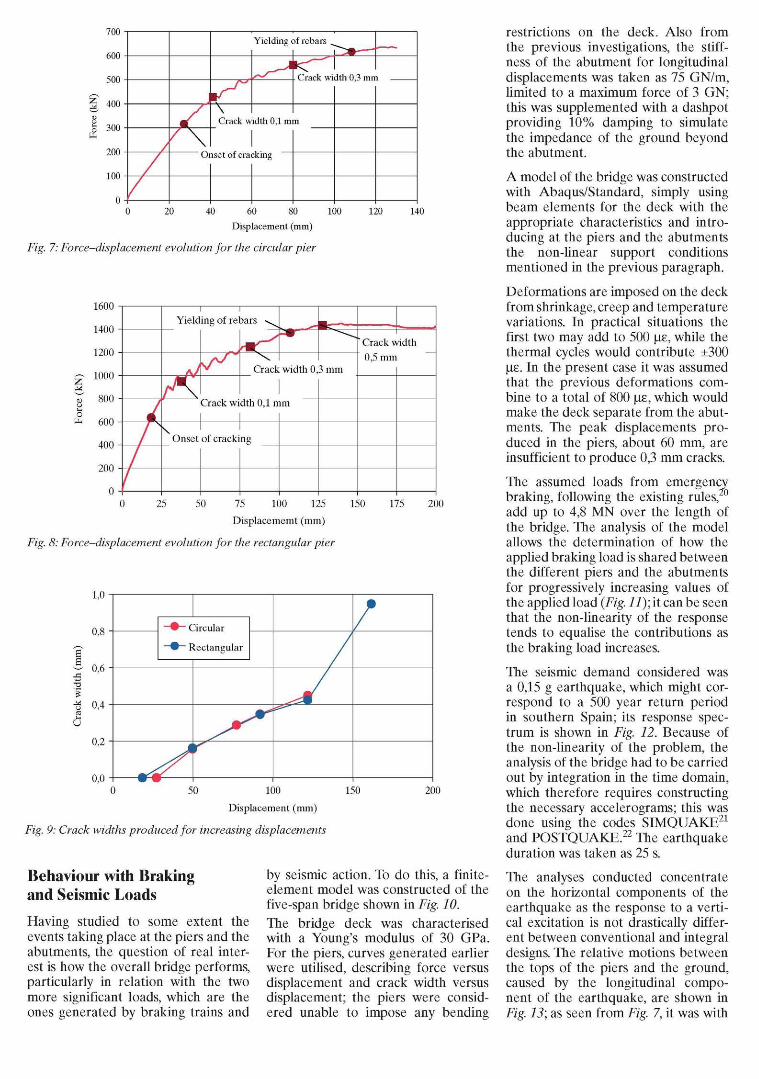
and between the cracks developed in the concrete. However, the more important results are the ones shown in Fig. 7 for the pair of piers with a circular cross-section and Fig. 8 for the pier of rectangular section; the figures describe the evolution of the force for increasing relative displacements. Several particularly significant events have been highlighted in the force-displacement curves: the onset of concrete cracking, the points at which crack widths reach certain thresholds and the onset of plastic yielding of the reinforcing bars. The progress of crack width with increasing relative displacements is shown in Fig. 9 for the two types of piers considered. Although the details are not given here, the force-displacement curves generated are consistent with those provided by existing concrete codes.
As a result of these investigations, it must be concluded that the phenomena of interest can be modelled with considerable detail. The models show that the typical reinforced concrete piers have a rather ductile response, which ensures that they will behave adequately under the type of demands that are characteristic of integral bridges. In the examples shown, crack widths of 0,3 mm develop only when relative displacements within the pier reach about 80 mm; likewise, yielding of the reinforcement requires relative displacements of about 110 mm. Such observations imply that reinforced concrete piers constitute a good structural option for integral bridges, as their response introduces only moderate limitations on the design of the bridge.
Pressure (Pa) +3,348e+05 +2,000e+05 +l,800e+05 +l,600e+05 +l,400e+05 +l,200e+05 +l,000e+05 +8,000e+04 +6,000e+04 +4,000e+04 +2,000e+04 +0,000e+00
Plastic strain ( - )
+2,000e-02 +l,800e-02 +l,600e-02 +l,400e-02 +l,200e-02 +l,000e-02 +8,000e-03 +6,000e-03 +4,000e-03 +2,000e-03 +0,000e+00
Fig. 5: Contact pressures (Pa) after 100 yearly cycles Fig. 6: Crack pattern developed in cylindrical piers
20 40 60 80 100 120 140 Displacement (mm)
Fig. 7: Force-displacement evolution for the circular pier
1600
1400
1200
£ 1000 M ^ 800 o
fe 600
400
200
0 0 25 50 75 100 125 150 175 200
Displacememt (mm)
Fig. 8: Force-displacement evolution for the rectangular pier
Yielding of rebars \
Onset
Crack
Crack width 0,1 n
of cracki ng
width 0
ím
3 mm
' Crack width
0,5 mm
u
1,0
0,8
0,6
0,4
0,2
0,0
9 Circular
• Rectangular
0 50 100
Displacement (mm)
Fig. 9: Crack widths produced for increasing displacements
150 200
Behaviour with Braking and Seismic Loads
Having studied to some extent the events taking place at the piers and the abutments, the question of real interest is how the overall bridge performs, particularly in relation with the two more significant loads, which are the ones generated by braking trains and
by seismic action. To do this, a finite-element model was constructed of the five-span bridge shown in Fig. 10. The bridge deck was characterised with a Young's modulus of 30 GPa. For the piers, curves generated earlier were utilised, describing force versus displacement and crack width versus displacement; the piers were considered unable to impose any bending
restrictions on the deck. Also from the previous investigations, the stiffness of the abutment for longitudinal displacements was taken as 75 GN/m, limited to a maximum force of 3 GN; this was supplemented with a dashpot providing 10% damping to simulate the impedance of the ground beyond the abutment.
A model of the bridge was constructed with Abaqus/Standard, simply using beam elements for the deck with the appropriate characteristics and introducing at the piers and the abutments the non-linear support conditions mentioned in the previous paragraph.
Deformations are imposed on the deck from shrinkage, creep and temperature variations. In practical situations the first two may add to 500 |J£, while the thermal cycles would contribute ±300 |j£. In the present case it was assumed that the previous deformations combine to a total of 800 |j£, which would make the deck separate from the abutments. The peak displacements produced in the piers, about 60 mm, are insufficient to produce 0,3 mm cracks.
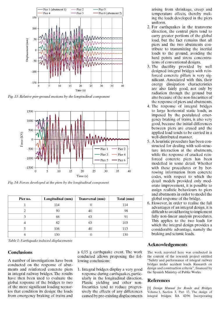
The assumed loads from emergency braking, following the existing rules, add up to 4,8 MN over the length of the bridge. The analysis of the model allows the determination of how the applied braking load is shared between the different piers and the abutments for progressively increasing values of the applied load (Fig. 11); it can be seen that the non-linearity of the response tends to equalise the contributions as the braking load increases.
The seismic demand considered was a 0,15 g earthquake, which might correspond to a 500 year return period in southern Spain; its response spectrum is shown in Fig. 12. Because of the non-linearity of the problem, the analysis of the bridge had to be carried out by integration in the time domain, which therefore requires constructing the necessary accelerograms; this was done using the codes SIMQUAKE21
and POSTQUAKE.22 The earthquake duration was taken as 25 s.
The analyses conducted concentrate on the horizontal components of the earthquake as the response to a vertical excitation is not drastically different between conventional and integral designs. The relative motions between the tops of the piers and the ground, caused by the longitudinal component of the earthquake, are shown in Fig. 13; as seen from Fig. 7, it was with
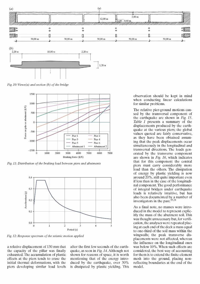
(a) íf$
12,00 m 2,00 m
1,00-0,60 m
mmmmmmmm&sm
30,00 m .
-r — *-30,00 m 30,00 m 30,00 m 30,00 m
(b) 2,20 M 10,00 M 2,20 M
1,20 M
Fig. 10: Views (a) and section (b) of the bridge
1500
1000
500
-500
-1000
-1500
Pier 1 — Pier 2
Pier 3 - Pier 4
Pier 5 Pier 6 — Abutment 1 Abutment 2
— i 1 1 1 1000 2000 3000 4000
Braking force (kN)
5000 6000 7000
Fig. 11: Distribution of the braking load between piers and abutments
0 0 -
/ \
1
0 1 2 3
Period (s)
Fig. 12: Response spectrum of the seismic motion applied
a relative displacement of 130 mm that the capacity of the pillar was finally exhausted. The accumulation of plastic effects at the piers tends to erase the initial thermal deformations, with the piers developing similar load levels
after the first few seconds of the earthquake, as seen in Fig. 14. Although not shown for reasons of space, it is worth mentioning that of the energy introduced by the earthquake, over 30% is dissipated by plastic yielding. This
observation should be kept in mind when conducting linear calculations for similar problems.
The relative pier-ground motions caused by the transversal component of the earthquake are shown in Fig. 15. Table 1 presents a summary of the displacements produced by the earthquake at the various piers; the global values quoted are fairly conservative, as they have been obtained assuming that the peak displacements occur simultaneously in the longitudinal and transversal directions. The loads generated by the transverse component are shown in Fig. 16, which indicates that for this component the central piers must carry considerably more load than the others. The dissipation of energy by plastic yielding is now around 20%, still quite important even if less than in the case of the longitudinal component. The good performance of integral bridges under earthquake loads is relatively intuitive, but has also been documented by a number of investigators in the past. '24
As a final note, no masses were introduced in the model to represent explicitly the mass of the abutment soil. This was thought unnecessary but, for verification, the analyses were repeated placing at each end of the deck a mass equal to one-third of the soil mass within the wingwalls; the peak transverse displacements were not affected, whereas the influence on the longitudinal ones was below 10%. When such effects are considered, the best way of accounting for them is to extend the finite-element mesh into the ground, placing non-reflecting boundaries at the end of the model.
150
100
50
Q -50
-100
-150
Pier 1 (abutment 1) Pier 2 Pier 3 Pier 4 Pier 5 Pier 6 (abutment 2)
fl I
Iff
i i I m i
10 15 20 25 30 35
Time (s)
40
Fig. 13: Relative pier-ground motions by the longitudinal component
1500
o
AM/V\ftftA~— • Pier 1
• Pier 3
• Pier 5
• Pier 2
• Pier 4
• Pier 6
15 20 25 30
Time (s)
Fig. 14: Forces developed at the piers by the longitudinal component
35 40
Pier no.
1
2
3
4
5
6
Longitudinal (mm)
114
90
66
82
106
130
Transversal (mm)
0
40
63
63
40
0
Total (mm)
114
98
91
103
113
130
Table 1: Earthquake induced displacements
Conclusions
A number of investigations have been conducted on the response of abutments and reinforced concrete piers in integral railway bridges. The results have then been used to evaluate the global response of the bridges to two of the more significant loading scenarios that condition its design: the loads from emergency braking of trains and
a 0,15 g earthquake event. The work conducted allows proposing the following conclusions:
1. Integral bridges display a very good response during earthquakes, particularly in the longitudinal direction. Plastic yielding and other non-linearities tend to reduce progressively the effects of any differences caused by pre-existing displacements
arising from shrinkage, creep and temperature effects, thereby making the loads developed in the piers uniform.
2. For earthquakes in the transverse direction, the central piers tend to carry greater portions of the global load, but the fact remains that all piers and the two abutments contribute to transmitting the inertial loads to the ground, avoiding the hard points and stress concentrations of conventional designs.
3. The ductility provided by well designed integral bridges with reinforced concrete pillars is very significant. Associated with this, their energy dissipation characteristics are also fairly good, not only by radiation through the ground but also because of the non-linearities of the response of piers and abutments.
4. The response of integral bridges to large horizontal static loads, as imposed by the postulated emergency braking of trains, is also very good, because the initial differences between piers are erased and the applied load tends to be carried in a well-distributed manner.
5. A heuristic procedure has been constructed for dealing with soil-structure interaction at the abutments, while the response of cracked reinforced concrete piers has been modelled in some detail. Whether with these procedures or by borrowing information from concrete codes, with respect to which the detail models provided only moderate improvement, it is possible to assign realistic behaviours to piers and abutments in order to model the global response of the bridge.
6. However, in order to realise the full advantages of an integral design, it is difficult to avoid having to implement fully non-linear analysis procedures. This applies to the two loads for which the integral design provides a considerable advantage, namely the braking and seismic loads.
Acknowledgements
The work reported here was conducted in the context of the research project entitled "Safety and performance of integral railway bridges under accident loads. Research on design and construction criteria", financed by the Spanish Ministry of Public Works.
References
[1] Design Manual for Roads and Bridges. Volume 1, Section 3, Part 12. The design of integral bridges. BA 42/96 Incorporating
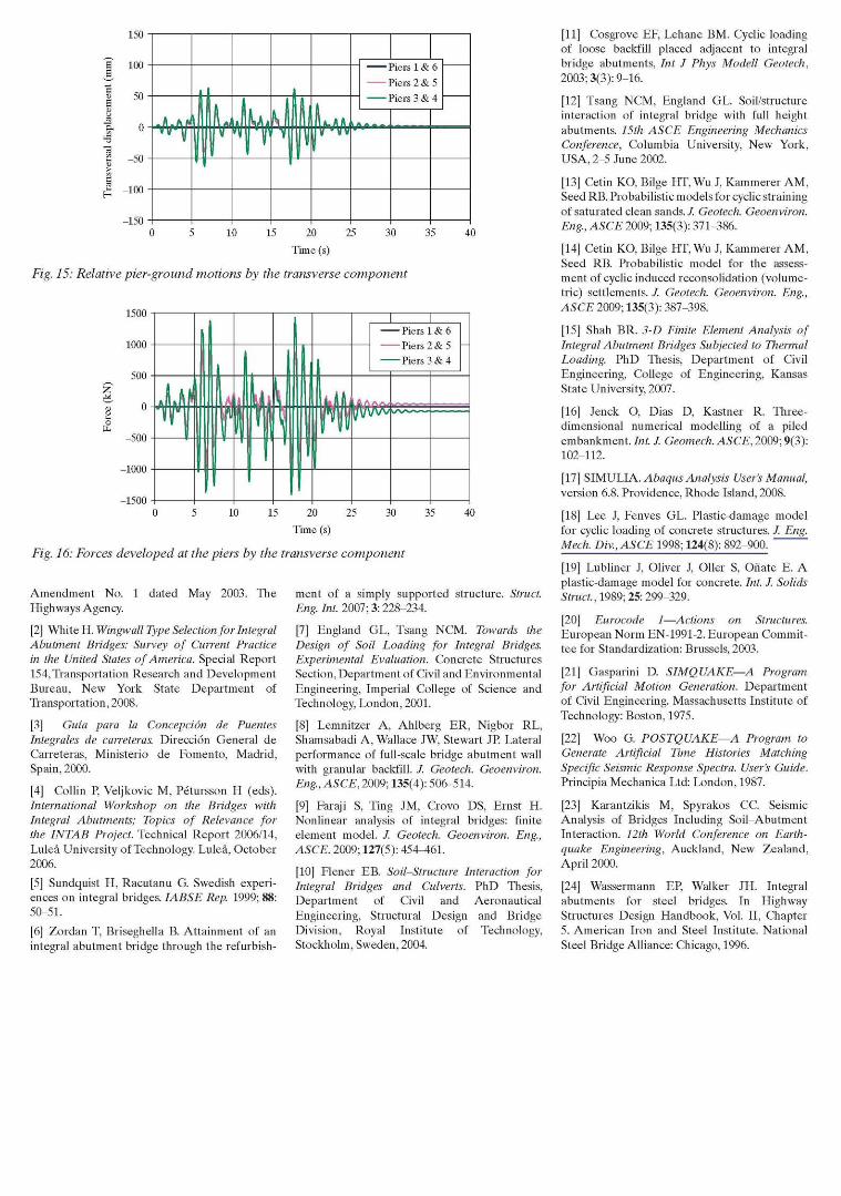
Fig. 15: Relative pier-ground motions by the transverse component
15 20 25
Time (s)
40
Fig. 16: Forces developed at the piers by the transverse component
Amendment No. 1 dated May 2003. The Highways Agency.
[2] White H. Wingwall Type Selection for Integral Abutment Bridges: Survey of Current Practice in the United States of America. Special Report 154, Transportation Research and Development Bureau, New York State Department of Transportation, 2008.
[3] Guía para la Concepción de Puentes Integrales de carreteras. Dirección General de Carreteras, Ministerio de Fomento, Madrid, Spain, 2000.
[4] Collin P, Veljkovic M, Pétursson H (eds). International Workshop on the Bridges with Integral Abutments; Topics of Relevance for the INTAB Project. Technical Report 2006/14, Luleá University of Technology. Luleá, October 2006.
[5] Sundquist H, Racutanu G. Swedish experiences on integral bridges. IABSE Rep. 1999; 88: 50-51.
[6] Zordan T, Briseghella B. Attainment of an integral abutment bridge through the refurbish
ment of a simply supported structure. Struct. Eng. Int. 2007; 3: 228-234.
[7] England GL, Tsang NCM. Towards the Design of Soil Loading for Integral Bridges. Experimental Evaluation. Concrete Structures Section, Department of Civil and Environmental Engineering, Imperial College of Science and Technology, London, 2001.
[8] Lemnitzer A, Ahlberg ER, Nigbor RL, Shamsabadi A, Wallace JW, Stewart JP. Lateral performance of full-scale bridge abutment wall with granular backfill. /. Geotech. Geoenviron. Eng, ASCE, 2009; 135(4): 506-514.
[9] Faraji S, Ting JM, Crovo DS, Ernst H. Nonlinear analysis of integral bridges: finite element model. /. Geotech. Geoenviron. Eng, ASCE. 2009; 127(5): 454-461.
[10] Flener EB. Soil-Structure Interaction for Integral Bridges and Culverts. PhD Thesis, Department of Civil and Aeronautical Engineering, Structural Design and Bridge Division, Royal Institute of Technology, Stockholm, Sweden, 2004.
[11] Cosgrove EF, Lehane BM. Cyclic loading of loose backfill placed adjacent to integral bridge abutments, Int I Phys Modell Geotech. 2003; 3(3): 9-16.
[12] Tsang NCM, England GL. Soil/structure interaction of integral bridge with full height abutments. 15th ASCE Engineering Mechanics Conference, Columbia University, New York, USA, 2-5 June 2002.
[13] Cetin KO, Bilge HT, Wu J, Kammerer AM, Seed RB. Probabilistic models for cyclic straining of saturated clean sands. /. Geotech. Geoenviron. Eng, ASCE 2009; 135(3): 371-386.
[14] Cetin KO, Bilge HT, Wu J, Kammerer AM, Seed RB. Probabilistic model for the assessment of cyclic induced reconsolidation (volumetric) settlements. /. Geotech. Geoenviron. Eng, ASCE 2009; 135(3): 387-398.
[15] Shah BR. 3-D Finite Element Analysis of Integral Abutment Bridges Subjected to Thermal Loading. PhD Thesis, Department of Civil Engineering, College of Engineering, Kansas State University, 2007.
[16] Jenck O, Dias D, Kastner R. Three-dimensional numerical modelling of a piled embankment. Int. I. Geomech. ASCE, 2009; 9(3): 102-112.
[17] SIMULIA. Abaqus Analysis User's Manual, version 6.8. Providence, Rhode Island, 2008.
[18] Lee J, Fenves GL. Plastic-damage model for cyclic loading of concrete structures. /. Eng. Mech. Div.,ASCE 1998; 124(8): 892-900.
[19] Lubliner J, Oliver J, Oiler S, Oñate E. A plastic-damage model for concrete. Int. I. Solids Struct., 1989; 25:299-329.
[20] Eurocode 1—Actions on Structures. European Norm EN-1991-2. European Committee for Standardization: Brussels, 2003.
[21] Gasparini D. SIMQUAKE—A Program for Artificial Motion Generation. Department of Civil Engineering. Massachusetts Institute of Technology: Boston, 1975.
[22] Woo G. POSTQUAKE—A Program to Generate Artificial Time Histories Matching Specific Seismic Response Spectra. User's Guide. Principia Mechanica Ltd: London, 1987.
[23] Karantzikis M, Spyrakos CC. Seismic Analysis of Bridges Including Soil-Abutment Interaction. 12th World Conference on Earthquake Engineering, Auckland, New Zealand, April 2000.
[24] Wassermann EP, Walker JH. Integral abutments for steel bridges. In Highway Structures Design Handbook, Vol. II, Chapter 5. American Iron and Steel Institute. National Steel Bridge Alliance: Chicago, 1996.