instrumentation documents
DESCRIPTION
Sistemas de control y modos de control.TRANSCRIPT
Chapter 7
Instrumentation documents
Every technical discipline has its own standardized way(s) of making descriptive diagrams, andinstrumentation is no exception. The scope of instrumentation is so broad, however, that no oneform of diagram is sufficient to capture all we might need to represent. This chapter will discussthree different types of instrumentation diagrams:
• Process Flow Diagrams (PFDs)
• Process and Instrument diagrams (P&IDs)
• Loop diagrams (“loop sheets”)
• Functional diagrams
At the highest level, the instrument technician is interested in the interconnections of processvessels, pipes, and flow paths of process fluids. The proper form of diagram to represent the “bigpicture” of a process is called a process flow diagram. Individual instruments are sparsely representedin a PFD, because the focus of the diagram is the process itself.
At the lowest level, the instrument technician is interested in the interconnections of individualinstruments, including all the wire numbers, terminal numbers, cable types, instrument calibrationranges, etc. The proper form of diagram for this level of fine detail is called a loop diagram. Here,the process vessels and piping are sparsely represented, because the focus of the diagram is theinstruments themselves.
Process and instrument diagrams (P&IDs) lie somewhere in the middle between process flowdiagrams and loop diagrams. A P&ID shows the layout of all relevant process vessels, pipes, andmachinery, but with instruments superimposed on the diagram showing what gets measured andwhat gets controlled. Here, one can view the flow of the process as well as the “flow” of informationbetween instruments measuring and controlling the process.
Functional diagrams are used for an entirely different purpose: to document the strategy of acontrol system. In a functional diagram, emphasis is placed on the algorithms used to control aprocess, as opposed to piping, wiring, or instrument connections. These diagrams are commonlyfound within the power generation industry, but are sometimes used in other industries as well.
391
392 CHAPTER 7. INSTRUMENTATION DOCUMENTS
An instrument technician must often switch between different diagrams when troubleshooting acomplex control system. There is simply too much detail for any one diagram to show everything.Even if the page were large enough, a “show everything” diagram would be so chock-full of detailsthat it would be difficult to follow any one line of details you happened to be interested in at anyparticular time. The narrowing of scope with the progression from PFD to loop diagram may bevisualized as a process of “zooming in,” as though one were viewing a process through the lens ofa microscope at different powers. First you begin with a PFD or P&ID to get an overview of theprocess, to see how the major components interact. Then, once you have identified which instrument“loop” you need to investigate, you go to the appropriate loop diagram to see the interconnectiondetails of that instrument system so you know where to connect your test equipment and whatsignals you expect to find when you do.
Another analogy for this progression of documents is a map, or more precisely, a globe, anatlas, and a city street map. The globe gives you the “big picture” of the Earth, countries, andmajor cities. An atlas allows you to “zoom in” to see details of particular provinces, states, andprincipalities, and the routes of travel connecting them all. A city map shows you major and minorroads, canals, alleyways, and perhaps even some addresses in order for you to find your way to aparticular destination. It would be impractical to have a globe large enough to show you all thedetails of every city! Furthermore, a globe comprehensive enough to show you all these detailswould have to be updated very frequently to keep up with all cities’ road changes. There is a certaineconomy inherent to the omission of fine details, both in ease of use and in ease of maintenance.
7.1. PROCESS FLOW DIAGRAMS 393
7.1 Process Flow Diagrams
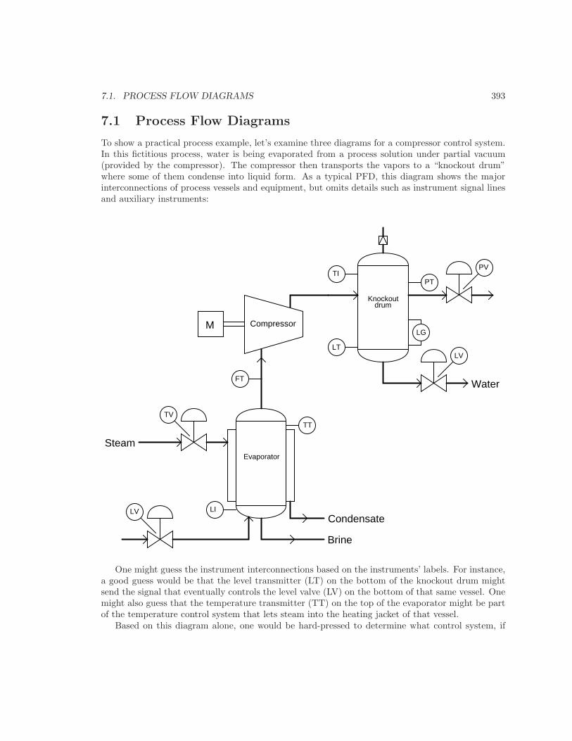
To show a practical process example, let’s examine three diagrams for a compressor control system.In this fictitious process, water is being evaporated from a process solution under partial vacuum(provided by the compressor). The compressor then transports the vapors to a “knockout drum”where some of them condense into liquid form. As a typical PFD, this diagram shows the majorinterconnections of process vessels and equipment, but omits details such as instrument signal linesand auxiliary instruments:
CompressorM
Evaporator
Steam
Condensate
Brine
Water
LILV
TTTV
PT
Knockoutdrum
PVTI
LG
LVLT
FT
One might guess the instrument interconnections based on the instruments’ labels. For instance,a good guess would be that the level transmitter (LT) on the bottom of the knockout drum mightsend the signal that eventually controls the level valve (LV) on the bottom of that same vessel. Onemight also guess that the temperature transmitter (TT) on the top of the evaporator might be partof the temperature control system that lets steam into the heating jacket of that vessel.
Based on this diagram alone, one would be hard-pressed to determine what control system, if

394 CHAPTER 7. INSTRUMENTATION DOCUMENTS
any, controls the compressor itself. All the PFD shows relating directly to the compressor is a flowtransmitter (FT) on the suction line. This level of uncertainty is perfectly acceptable for a PFD,because its purpose is merely to show the general flow of the process itself, and only a bare minimumof control instrumentation.
7.2. PROCESS AND INSTRUMENT DIAGRAMS 395
7.2 Process and Instrument Diagrams
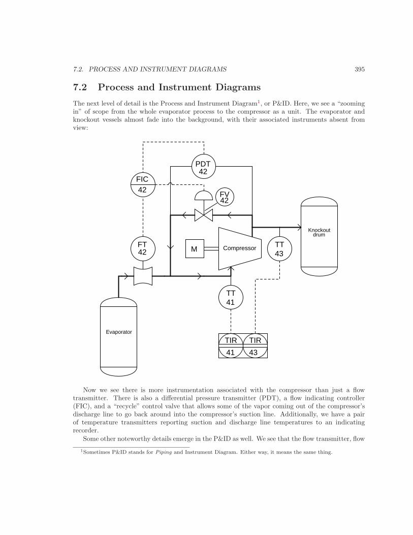
The next level of detail is the Process and Instrument Diagram1, or P&ID. Here, we see a “zoomingin” of scope from the whole evaporator process to the compressor as a unit. The evaporator andknockout vessels almost fade into the background, with their associated instruments absent fromview:
CompressorM
Evaporator
Knockoutdrum
FT
PDT
FIC
FV42
42
42
42
TT41
TIR
41
TIR
43
TT43
Now we see there is more instrumentation associated with the compressor than just a flowtransmitter. There is also a differential pressure transmitter (PDT), a flow indicating controller(FIC), and a “recycle” control valve that allows some of the vapor coming out of the compressor’sdischarge line to go back around into the compressor’s suction line. Additionally, we have a pairof temperature transmitters reporting suction and discharge line temperatures to an indicatingrecorder.
Some other noteworthy details emerge in the P&ID as well. We see that the flow transmitter, flow
1Sometimes P&ID stands for Piping and Instrument Diagram. Either way, it means the same thing.
396 CHAPTER 7. INSTRUMENTATION DOCUMENTS
controller, pressure transmitter, and flow valve all bear a common number: 42. This common “loopnumber” indicates these four instruments are all part of the same control system. An instrumentwith any other loop number is part of a different control system, measuring and/or controlling someother function in the process. Examples of this include the two temperature transmitters and theirrespective recorders, bearing the loop numbers 41 and 43.
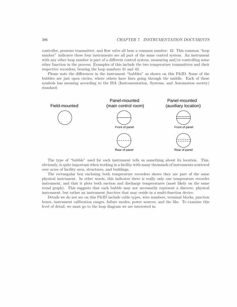
Please note the differences in the instrument “bubbles” as shown on this P&ID. Some of thebubbles are just open circles, where others have lines going through the middle. Each of thesesymbols has meaning according to the ISA (Instrumentation, Systems, and Automation society)standard:
Field-mountedPanel-mounted
(main control room)Panel-mounted
(auxiliary location)
Front of panel
Rear of panel
Front of panel
Rear of panel
The type of “bubble” used for each instrument tells us something about its location. This,obviously, is quite important when working in a facility with many thousands of instruments scatteredover acres of facility area, structures, and buildings.
The rectangular box enclosing both temperature recorders shows they are part of the samephysical instrument. In other words, this indicates there is really only one temperature recorderinstrument, and that it plots both suction and discharge temperatures (most likely on the sametrend graph). This suggests that each bubble may not necessarily represent a discrete, physicalinstrument, but rather an instrument function that may reside in a multi-function device.
Details we do not see on this P&ID include cable types, wire numbers, terminal blocks, junctionboxes, instrument calibration ranges, failure modes, power sources, and the like. To examine thislevel of detail, we must go to the loop diagram we are interested in.
7.3. LOOP DIAGRAMS 397
7.3 Loop diagrams
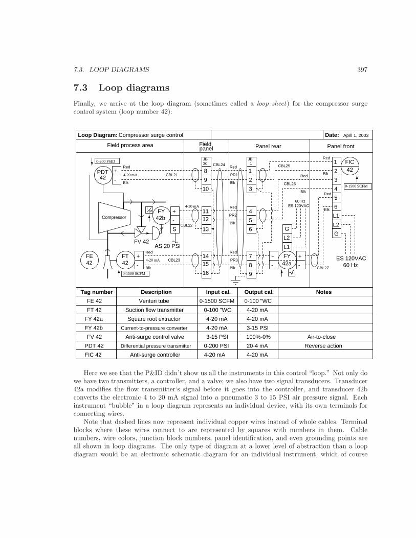
Finally, we arrive at the loop diagram (sometimes called a loop sheet) for the compressor surgecontrol system (loop number 42):
+
-
L1
L2
G
ES 120VAC60 Hz
Fieldpanel
Field process area
Loop Diagram: Date:
8
9
April 1, 2003
PDT
Compressor surge control
+
-
FT
42
42
Compressor+
-
FY42b
10
1112
13
1415
16
JB30
1
2
3
4
5
6
7
8
9
+
-
FY
Panel frontPanel rear
+
- 42a
L1
L2
G
ES 120VAC60 Hz
FIC42
JB1
S
AS 20 PSI
0-200 PSID
4-20 mA
IP
0-1500 SCFM
4-20 mA
4-20 mA
0-1500 SCFM
CBL21
CBL22
CBL23
CBL24 CBL25
CBL26
CBL27
PR1
PR2
PR3
1
2
3
4
5
6
FV 42
Red
Blk
Red
Blk
Red
Blk
Red
Blk
Red
Blk Red
Blk
Red
Blk
Red
Blk
Tag number Description Input cal. Output cal. Notes
FT 42 Suction flow transmitter
FE42
FE 42 Venturi tube 0-1500 SCFM 0-100 "WC
0-100 "WC 4-20 mA
FY 42a Square root extractor 4-20 mA 4-20 mA
FY 42b Current-to-pressure converter 4-20 mA 3-15 PSI
FV 42 Anti-surge control valve 3-15 PSI
PDT 42 Differential pressure transmitter 0-200 PSI
100%-0% Air-to-close
Reverse action20-4 mA
FIC 42 Anti-surge controller 4-20 mA 4-20 mA
Here we see that the P&ID didn’t show us all the instruments in this control “loop.” Not only dowe have two transmitters, a controller, and a valve; we also have two signal transducers. Transducer42a modifies the flow transmitter’s signal before it goes into the controller, and transducer 42bconverts the electronic 4 to 20 mA signal into a pneumatic 3 to 15 PSI air pressure signal. Eachinstrument “bubble” in a loop diagram represents an individual device, with its own terminals forconnecting wires.
Note that dashed lines now represent individual copper wires instead of whole cables. Terminalblocks where these wires connect to are represented by squares with numbers in them. Cablenumbers, wire colors, junction block numbers, panel identification, and even grounding points areall shown in loop diagrams. The only type of diagram at a lower level of abstraction than a loopdiagram would be an electronic schematic diagram for an individual instrument, which of course
398 CHAPTER 7. INSTRUMENTATION DOCUMENTS
would only show details pertaining to that one instrument. Thus, the loop diagram is the mostdetailed form of diagram for a control system as a whole, and thus it must contain all detailsomitted by PFDs and P&IDs alike.
To the novice it may seem excessive to include such trivia as wire colors in a loop diagram. Tothe experienced instrument technician who has had to work on systems lacking such documenteddetail, this information is highly valued. The more detail you put into a loop diagram, the easierit makes the inevitable job of maintaining that system at some later date. When a loop diagramshows you exactly what wire color to expect at exactly what point in an instrumentation system,and exactly what terminal that wire should connect to, it becomes much easier to proceed with anytroubleshooting, calibration, or upgrade task.
Loop diagrams are fairly constrained in their layout. Field instruments are always placed on theleft-hand side, while control-panel or control-room instruments must be located on the right-handside. Text describing instrument tags, ranges, and notes are always placed on the bottom. UnlikePFDs and P&IDs where component layout is largely left to the whim of the designer drawing thediagram, loop sheets offer little room for creativity. This is intentional, as creativity and readabilityare mutually exclusive in cases where there is an immense amount of technical detail embedded ina diagram. It is simply easier to recognize details you’re looking for when you know exactly whereto look on the diagram to find them.
An interesting detail seen on this loop diagram is an entry specifying “input calibration” and“output calibration” for each and every instrument in the system. This is actually a very importantconcept to keep in mind when troubleshooting a complex instrumentation system: every instrumenthas at least one input and at least one output, with some sort of mathematical relationship betweenthe two. Diagnosing where a problem lies within a measurement or control system often reducesto testing various instruments to see if their output responses appropriately match their inputconditions.
For example, one way to test the flow transmitter in this system would be to subject it to anumber of different pressures within its range (specified in the diagram as 0 to 100 inches of watercolumn differential) and seeing whether or not the current signal output by the transmitter wasconsistently proportional to the applied pressure (e.g. 4 mA at 0 inches pressure, 20 mA at 100inches pressure, 12 mA at 50 inches pressure, etc.).
Given the fact that a calibration error or malfunction in any one of these instruments can causea problem for the control system as a whole, it is nice to know there is a way to determine whichinstrument is to blame and which instruments are not. This general principle holds true regardlessof the instrument’s type or technology. You can use the same input-versus-output test procedure toverify the proper operation of a pneumatic (3 to 15 PSI) level transmitter or an analog electronic(4 to 20 mA) flow transmitter or a digital (fieldbus) temperature transmitter alike. Each and everyinstrument has an input and an output, and there is always a predictable (and testable) correlationfrom one to the other.
7.3. LOOP DIAGRAMS 399
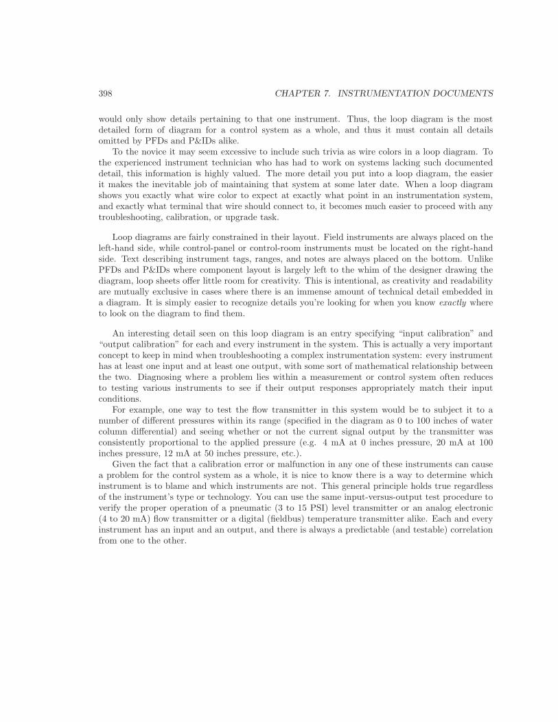
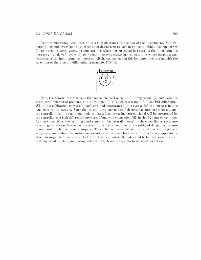
Another interesting detail seen on this loop diagram is the action of each instrument. You willnotice a box and arrow (pointing either up or down) next to each instrument bubble. An “up” arrow(↑) represents a direct-acting instrument: one whose output signal increases as the input stimulusincreases. A “down” arrow (↓) represents a reverse-acting instrument: one whose output signaldecreases as the input stimulus increases. All the instruments in this loop are direct-acting with theexception of the pressure differential transmitter PDT-42:
+
-PDT42
0-200 PSID
Here, the “down” arrow tells us the transmitter will output a full-range signal (20 mA) when itsenses zero differential pressure, and a 0% signal (4 mA) when sensing a full 200 PSI differential.While this calibration may seem confusing and unwarranted, it serves a definite purpose in thisparticular control system. Since the transmitter’s current signal decreases as pressure increases, andthe controller must be correspondingly configured, a decreasing current signal will be interpreted bythe controller as a high differential pressure. If any wire connection fails in the 4-20 mA current loopfor that transmitter, the resulting 0 mA signal will be naturally “seen” by the controller as a pressureover-range condition. Excessive pressure drop across a compressor is considered dangerous becauseit may lead to the compressor surging. Thus, the controller will naturally take action to preventsurge by commanding the anti-surge control valve to open, because it “thinks” the compressor isabout to surge. In other words, the transmitter is intentionally calibrated to be reverse-acting suchthat any break in the signal wiring will naturally bring the system to its safest condition.
400 CHAPTER 7. INSTRUMENTATION DOCUMENTS
7.4 Functional diagrams
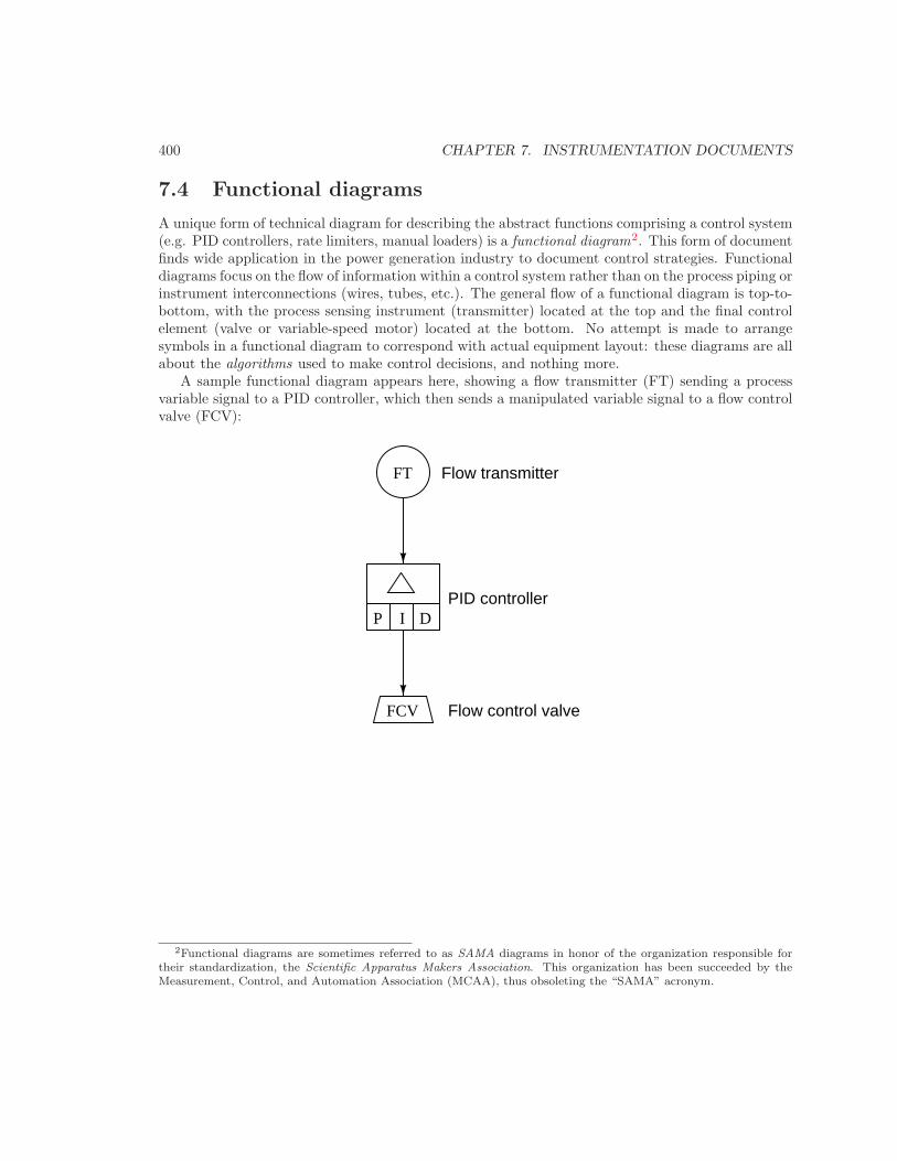
A unique form of technical diagram for describing the abstract functions comprising a control system(e.g. PID controllers, rate limiters, manual loaders) is a functional diagram2. This form of documentfinds wide application in the power generation industry to document control strategies. Functionaldiagrams focus on the flow of information within a control system rather than on the process piping orinstrument interconnections (wires, tubes, etc.). The general flow of a functional diagram is top-to-bottom, with the process sensing instrument (transmitter) located at the top and the final controlelement (valve or variable-speed motor) located at the bottom. No attempt is made to arrangesymbols in a functional diagram to correspond with actual equipment layout: these diagrams are allabout the algorithms used to make control decisions, and nothing more.
A sample functional diagram appears here, showing a flow transmitter (FT) sending a processvariable signal to a PID controller, which then sends a manipulated variable signal to a flow controlvalve (FCV):
P I D
FCV
FT Flow transmitter
PID controller
Flow control valve
2Functional diagrams are sometimes referred to as SAMA diagrams in honor of the organization responsible fortheir standardization, the Scientific Apparatus Makers Association. This organization has been succeeded by theMeasurement, Control, and Automation Association (MCAA), thus obsoleting the “SAMA” acronym.
7.4. FUNCTIONAL DIAGRAMS 401
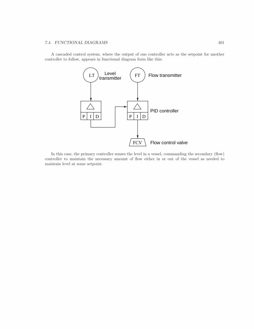
A cascaded control system, where the output of one controller acts as the setpoint for anothercontroller to follow, appears in functional diagram form like this:
P I D
FCV
FT Flow transmitter
PID controller
Flow control valve
P I D
LT Leveltransmitter
In this case, the primary controller senses the level in a vessel, commanding the secondary (flow)controller to maintain the necessary amount of flow either in or out of the vessel as needed tomaintain level at some setpoint.
402 CHAPTER 7. INSTRUMENTATION DOCUMENTS
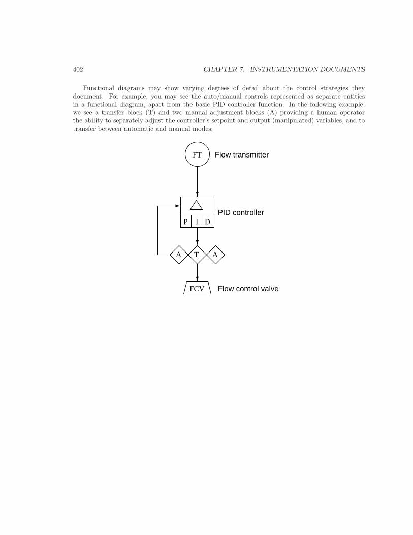
Functional diagrams may show varying degrees of detail about the control strategies theydocument. For example, you may see the auto/manual controls represented as separate entitiesin a functional diagram, apart from the basic PID controller function. In the following example,we see a transfer block (T) and two manual adjustment blocks (A) providing a human operatorthe ability to separately adjust the controller’s setpoint and output (manipulated) variables, and totransfer between automatic and manual modes:
P I D
FCV
FT Flow transmitter
PID controller
Flow control valve
TA A
7.5. INSTRUMENT AND PROCESS EQUIPMENT SYMBOLS 403
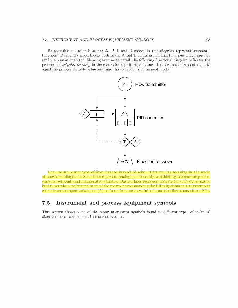
Rectangular blocks such as the ∆, P, I, and D shown in this diagram represent automaticfunctions. Diamond-shaped blocks such as the A and T blocks are manual functions which must beset by a human operator. Showing even more detail, the following functional diagram indicates thepresence of setpoint tracking in the controller algorithm, a feature that forces the setpoint value toequal the process variable value any time the controller is in manual mode:
P I D
FCV
FT Flow transmitter
PID controller
Flow control valve
T
A
A
T
Here we see a new type of line: dashed instead of solid. This too has meaning in the worldof functional diagrams. Solid lines represent analog (continuously variable) signals such as processvariable, setpoint, and manipulated variable. Dashed lines represent discrete (on/off) signal paths,in this case the auto/manual state of the controller commanding the PID algorithm to get its setpointeither from the operator’s input (A) or from the process variable input (the flow transmitter: FT).
7.5 Instrument and process equipment symbols
This section shows some of the many instrument symbols found in different types of technicaldiagrams used to document instrument systems.
404 CHAPTER 7. INSTRUMENTATION DOCUMENTS
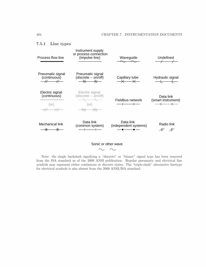
7.5.1 Line types
Pneumatic signal(continuous) (discrete -- on/off)
Pneumatic signal
(continuous) (discrete -- on/off)Electric signal Electric signal
(or) (or)
Capillary tube Hydraulic signal
Instrument supplyor process connection
Process flow line Waveguide Undefined(impulse line)
Mechanical linkData link Data link
(independent systems)(common system) Radio link
Sonic or other wave
Fieldbus networkData link
(smart instrument)
Note: the single backslash signifying a “discrete” or “binary” signal type has been removedfrom the ISA standard as of the 2009 ANSI publication. Regular pneumatic and electrical linesymbols may represent either continuous or discrete states. The “triple-slash” alternative linetypefor electrical symbols is also absent from the 2009 ANSI/ISA standard.
7.5. INSTRUMENT AND PROCESS EQUIPMENT SYMBOLS 405
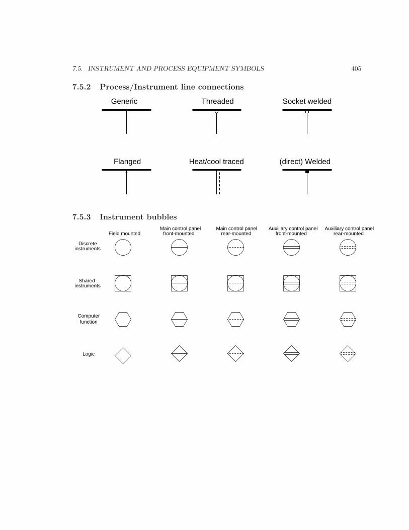
7.5.2 Process/Instrument line connections
Flanged
Threaded Socket welded
(direct) Welded
Generic
Heat/cool traced
7.5.3 Instrument bubbles
Field mountedMain control panel
front-mounted front-mountedAuxiliary control panel
Discrete instruments
Main control panelrear-mounted
Auxiliary control panelrear-mounted
Sharedinstruments
Computerfunction
Logic
406 CHAPTER 7. INSTRUMENTATION DOCUMENTS
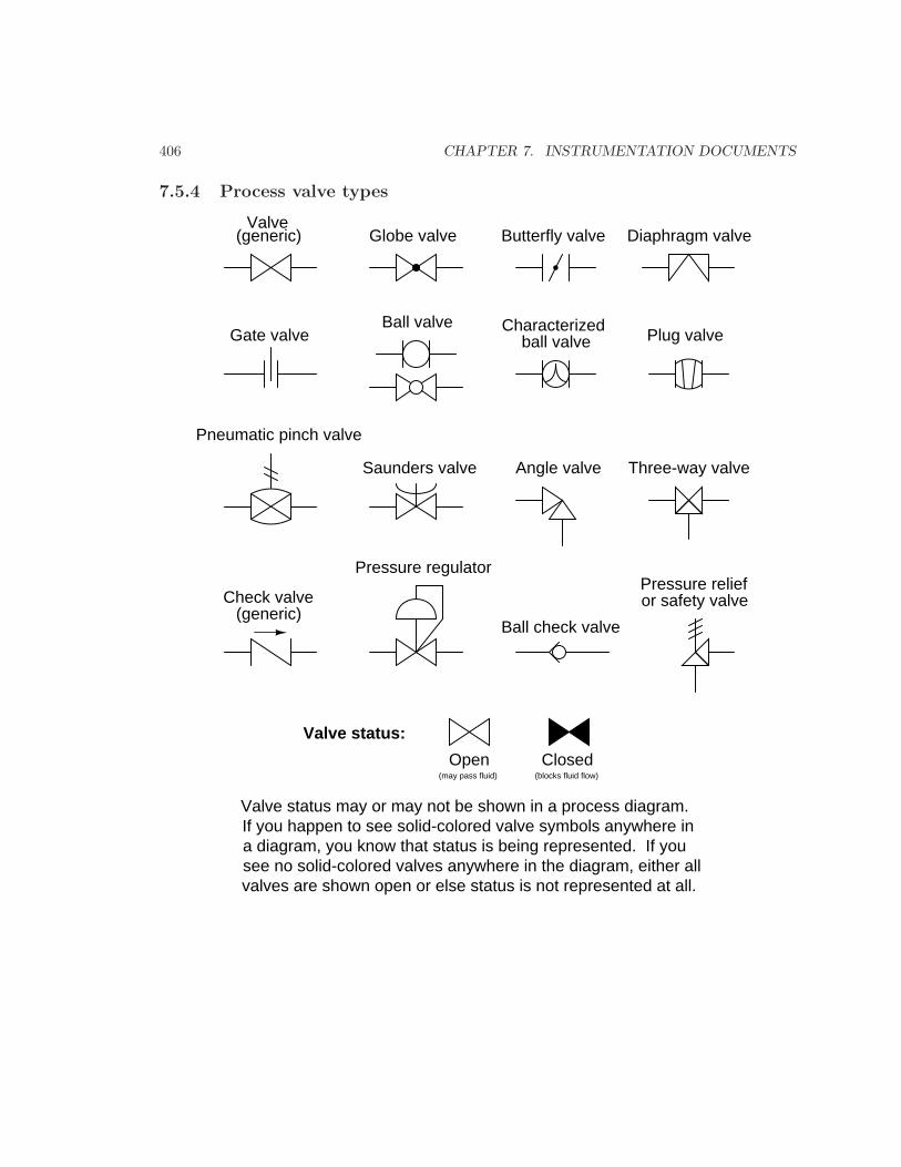
7.5.4 Process valve types
Valve(generic)
Ball valve
Butterfly valveGlobe valve
Characterizedball valve Plug valve
Saunders valve
Gate valve
Pneumatic pinch valve
Angle valve
Diaphragm valve
Three-way valve
Ball check valve
Check valve(generic)
Pressure regulatorPressure relief or safety valve
Valve status:
Open Closed(may pass fluid) (blocks fluid flow)
Valve status may or may not be shown in a process diagram.If you happen to see solid-colored valve symbols anywhere in a diagram, you know that status is being represented. If yousee no solid-colored valves anywhere in the diagram, either allvalves are shown open or else status is not represented at all.
7.5. INSTRUMENT AND PROCESS EQUIPMENT SYMBOLS 407
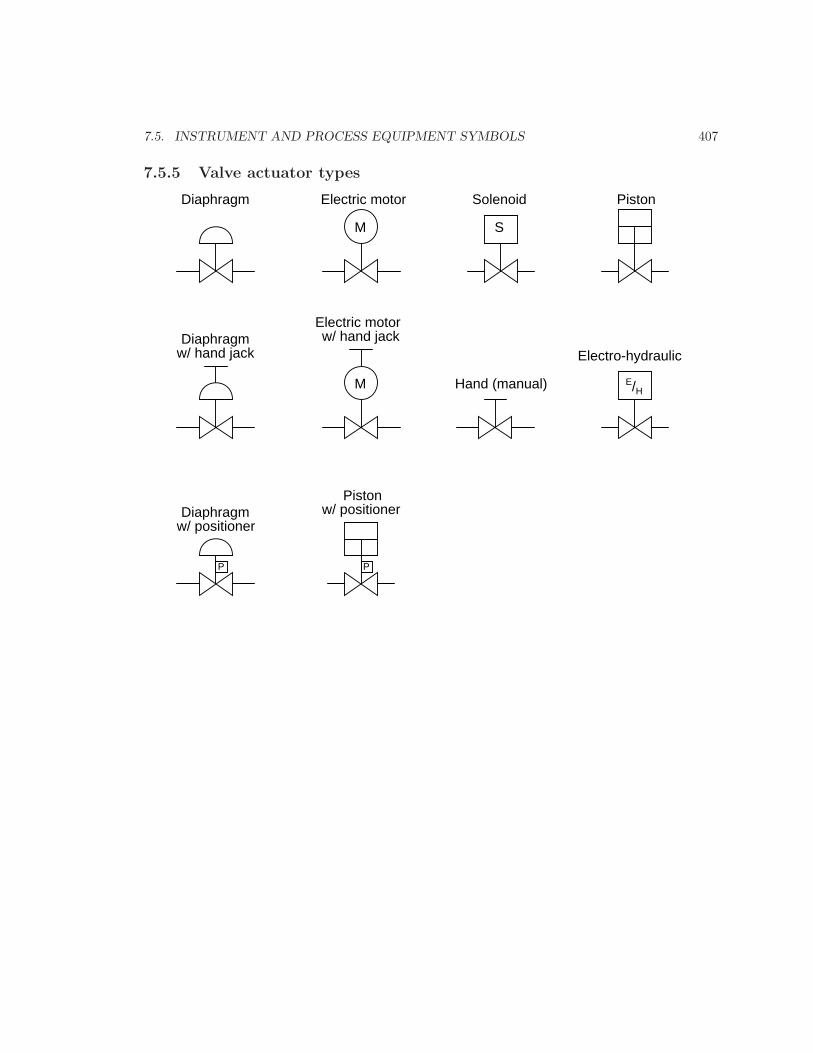
7.5.5 Valve actuator types
M S
PistonSolenoidElectric motorDiaphragm
E/H
Electro-hydraulic
Hand (manual)
Diaphragmw/ hand jack
M
w/ hand jackElectric motor
P
Diaphragmw/ positioner
Pistonw/ positioner
P
408 CHAPTER 7. INSTRUMENTATION DOCUMENTS
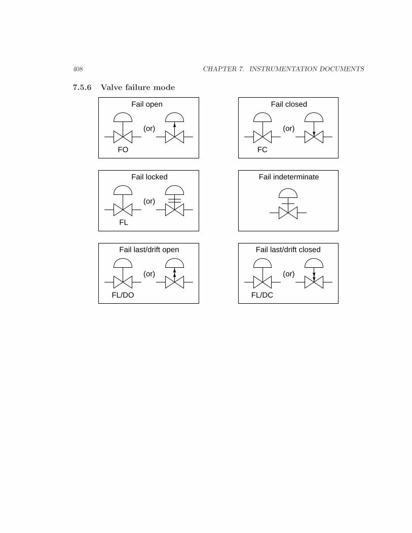
7.5.6 Valve failure mode
FO
Fail open
(or) (or)
FC
Fail closed
(or)
FL
Fail locked
(or) (or)
Fail last/drift open
FL/DO
Fail last/drift closed
FL/DC
Fail indeterminate
7.5. INSTRUMENT AND PROCESS EQUIPMENT SYMBOLS 409
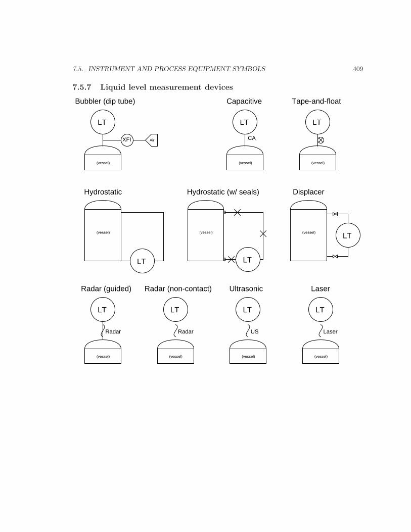
7.5.7 Liquid level measurement devices
Air
Bubbler (dip tube)
LT
XFI
LT LT
LT
Capacitive
CA
Hydrostatic
(vessel) (vessel) (vessel)
(vessel)LT
(vessel)
Displacer
Tape-and-float
LT
(vessel)
Hydrostatic (w/ seals)
LT
(vessel)
Radar (guided)
Radar
LT
(vessel)
Radar
Radar (non-contact)
LT
(vessel)
US
Ultrasonic
LT
(vessel)
Laser
Laser
410 CHAPTER 7. INSTRUMENTATION DOCUMENTS
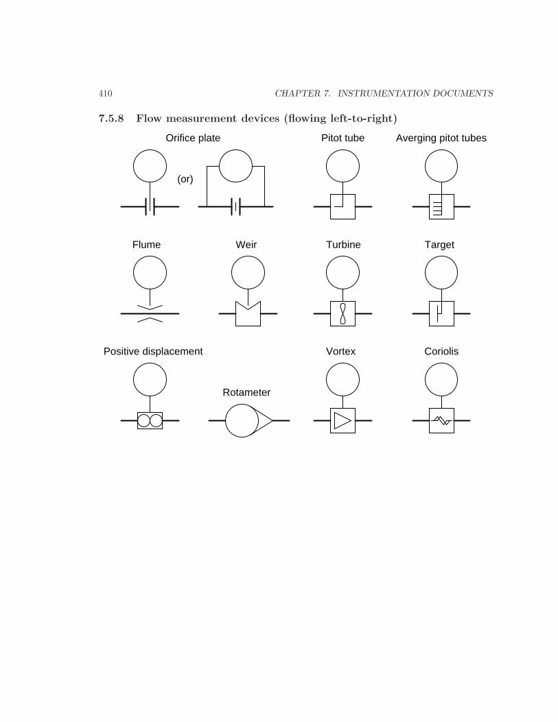
7.5.8 Flow measurement devices (flowing left-to-right)
Orifice plate
(or)
Pitot tube Averging pitot tubes
Flume Weir Turbine Target
Positive displacement
Rotameter
Vortex Coriolis
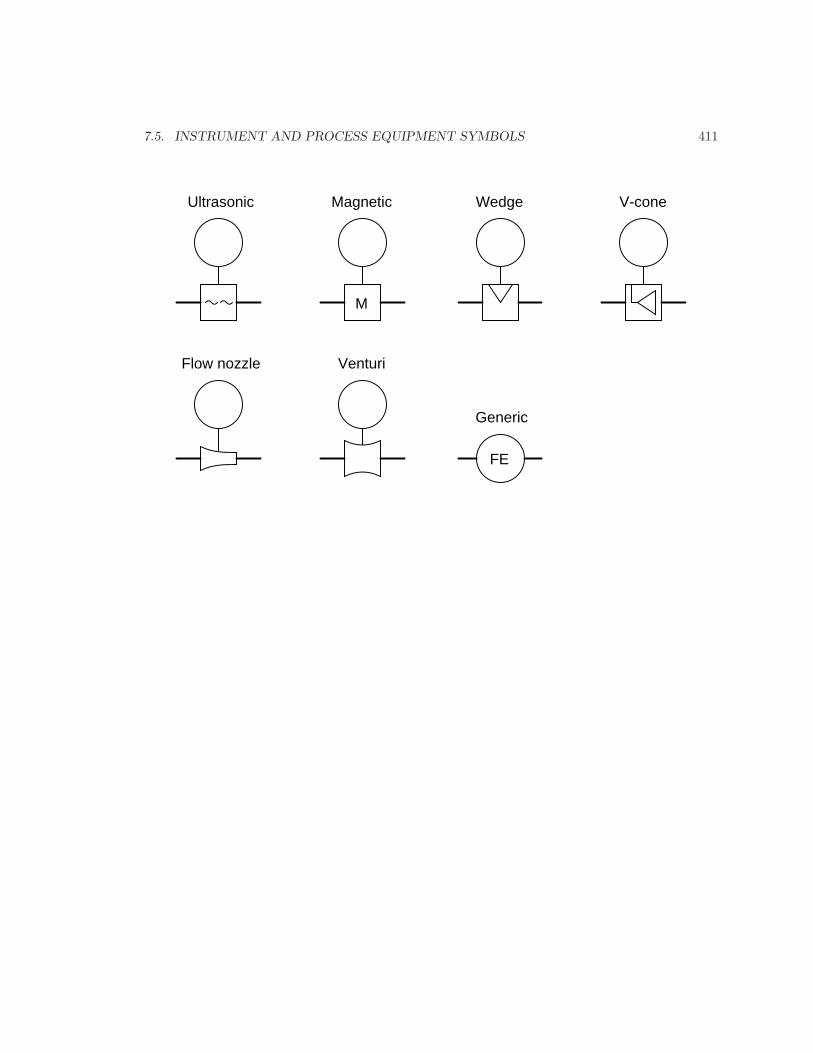
7.5. INSTRUMENT AND PROCESS EQUIPMENT SYMBOLS 411
Ultrasonic
M
Magnetic Wedge V-cone
Flow nozzle Venturi
FE
Generic
412 CHAPTER 7. INSTRUMENTATION DOCUMENTS
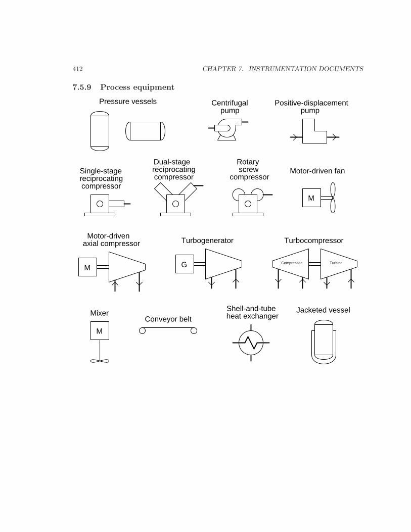
7.5.9 Process equipment
Pressure vessels
Single-stagereciprocatingcompressor
reciprocatingcompressor
Dual-stage
compressor
Rotaryscrew
Centrifugalpump
M
Motor-drivenaxial compressor
G
Turbogenerator Turbocompressor
Compressor Turbine
M
Motor-driven fan
M
MixerConveyor belt heat exchanger
Shell-and-tube
Positive-displacementpump
Jacketed vessel
7.5. INSTRUMENT AND PROCESS EQUIPMENT SYMBOLS 413
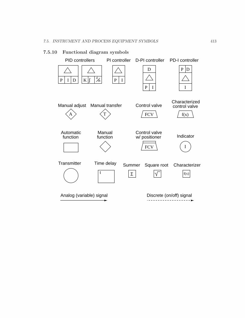
7.5.10 Functional diagram symbols
P I D K ∫ ddt P I
D
P I
P D
I
A T FCV f(x)
IFCV
t Σ f(x)
PID controllers PI controller D-PI controller PD-I controller
Manual adjust Manual transfer Control valveCharacterizedcontrol valve
Automaticfunction
Manualfunction
Control valvew/ positioner Indicator
Transmitter Time delay Summer Square root Characterizer
Analog (variable) signal Discrete (on/off) signal
414 CHAPTER 7. INSTRUMENTATION DOCUMENTS
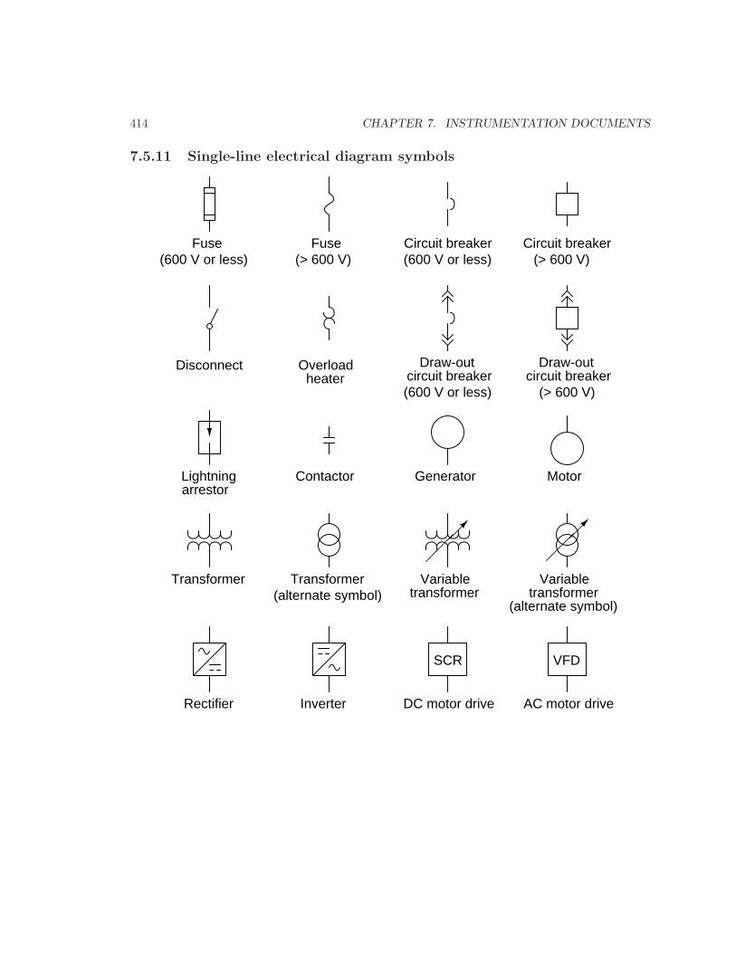
7.5.11 Single-line electrical diagram symbols
Fuse(600 V or less)
Fuse(> 600 V)
Circuit breaker(600 V or less)
Circuit breaker(> 600 V)
Draw-outcircuit breaker
Draw-outcircuit breaker
(600 V or less) (> 600 V)
Disconnect Overloadheater
Lightningarrestor
Contactor Generator Motor
Transformer Transformer(alternate symbol)
Variabletransformer
Variabletransformer
(alternate symbol)
Rectifier Inverter
SCR
DC motor drive
VFD
AC motor drive
7.5. INSTRUMENT AND PROCESS EQUIPMENT SYMBOLS 415
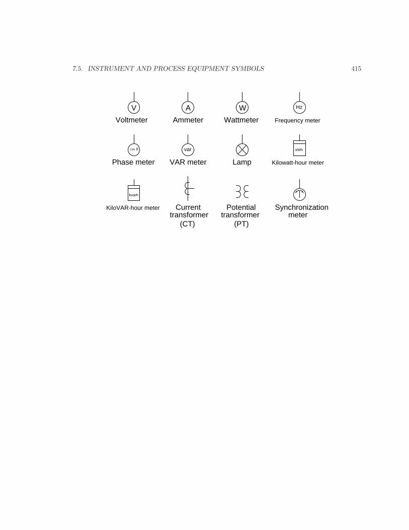
V
Voltmeter
A
Ammeter
W
Wattmeter
Hz
Frequency meter
var
VAR meter
cos θ
Phase meter
kWh
Kilowatt-hour meter
kvarh
KiloVAR-hour meter
Lamp
Currenttransformer
Potentialtransformer
Synchronizationmeter
(CT) (PT)
416 CHAPTER 7. INSTRUMENTATION DOCUMENTS
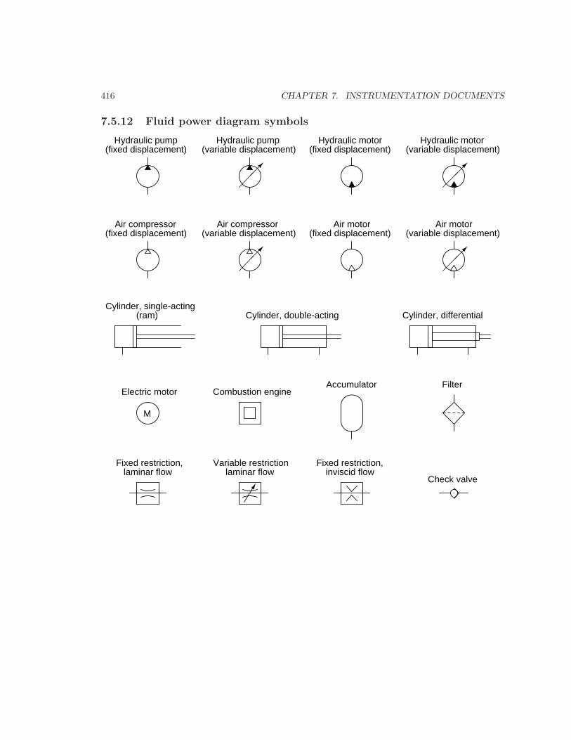
7.5.12 Fluid power diagram symbols
Hydraulic pump(fixed displacement)
Hydraulic pump(variable displacement)
Hydraulic motor(fixed displacement)
Hydraulic motor(variable displacement)
Air compressor(fixed displacement) (variable displacement) (fixed displacement) (variable displacement)
Air compressor Air motor Air motor
Cylinder, single-acting(ram) Cylinder, double-acting Cylinder, differential
Check valve
Accumulator
Variable restrictionFixed restriction,laminar flow laminar flow
Fixed restriction,inviscid flow
M
Electric motor Combustion engineFilter
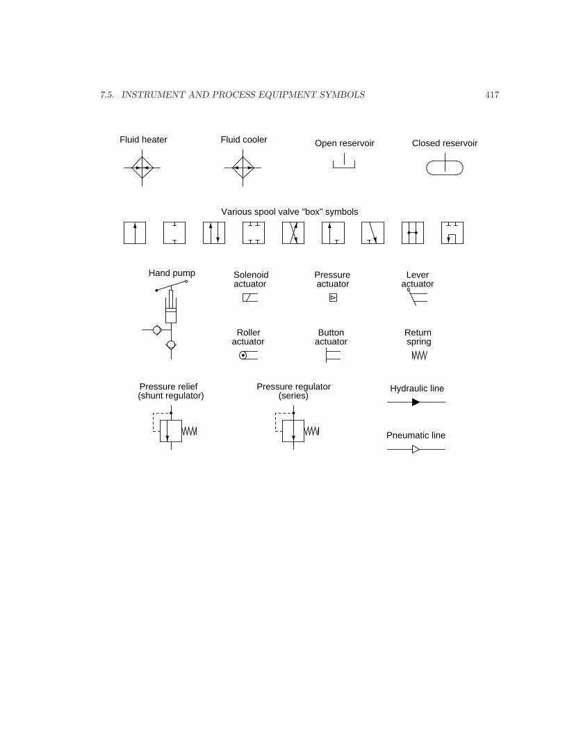
7.5. INSTRUMENT AND PROCESS EQUIPMENT SYMBOLS 417
Fluid heater Fluid cooler Open reservoir Closed reservoir
Various spool valve "box" symbols
Solenoidactuator
Pressureactuator
Leveractuator
Rolleractuator
Buttonactuator
Returnspring
Hand pump
Hydraulic line
Pneumatic line
Pressure relief(shunt regulator)
Pressure regulator(series)
418 CHAPTER 7. INSTRUMENTATION DOCUMENTS
7.6 Instrument identification tags
Up until this point, we have explored various types of instrumentation diagram, each one makingreference to different instruments by lettered identifiers such as TT (Temperature Transmitter), PDT(Pressure Differential Transmitter), or FV (Flow Valve), without formally defining all the lettersused to identify instruments. Part of the ISA 5.1 standard does exactly this, which is what we willnow investigate.
Each instrument within an instrumented facility should have its own unique identifying tagconsisting of a series of letters describing that instrument’s function, as well as a number identifyingthe particular loop it belongs to. An optional numerical prefix typically designates the larger areaof the facility in which the loop resides, and an optional alphabetical suffix designates multipleinstances of instruments within one loop.
For example, if we were to see an instrument bearing the tag FC-135, we would know it was aflow controller (FC) for loop number 135. In a large manufacturing facility with multiple processing“unit” areas, a tag such as this might be preceded by another number designating the unit area.For example, our hypothetical flow controller might be labeled 12-FC-135 (flow controller for loop#135, located in unit 12). If this loop happened to contain multiple controllers, we would needto distinguish them from each other by the use of suffix letters appended to the loop number (e.g.12-FC-135A, 12-FC-135B, 12-FC-135C).
Each and every instrument within a particular loop is first defined by the variable that loop seeksto sense or control, regardless of the physical construction of the instrument itself. Our hypotheticalflow controller FC-135, for example, may be physically identical to the level controller in loop #72(LC-72), or to the temperature controller in loop #288 (TC-288). What makes FC-135 a flowcontroller is the fact that the transmitter sensing the main process variable measures flow. Likewise,the identifying tag for every other instrument within that loop3 must begin with the letter “F”as well. This includes the final control element as well: in a level control loop, the transmitter isidentified as an “LT” even if the actual sensing element works on pressure (because the variablethat the loop strives to sense or control is actually level, even if indirectly sensed by pressure), thecontroller is identified as an “LC”, and the control valve throttling fluid flow is identified as an“LV”: every instrument in that level-controlling loop serves to help control level, and so its primaryfunction is to be a “level” instrument.
3Exceptions do exist to this rule. For example, in a cascade or feedforward loop where multiple transmittersfeed into one or more controllers, each transmitter is identified by the type of process variable it senses, and eachcontroller’s identifying tag follows suit.
7.6. INSTRUMENT IDENTIFICATION TAGS 419
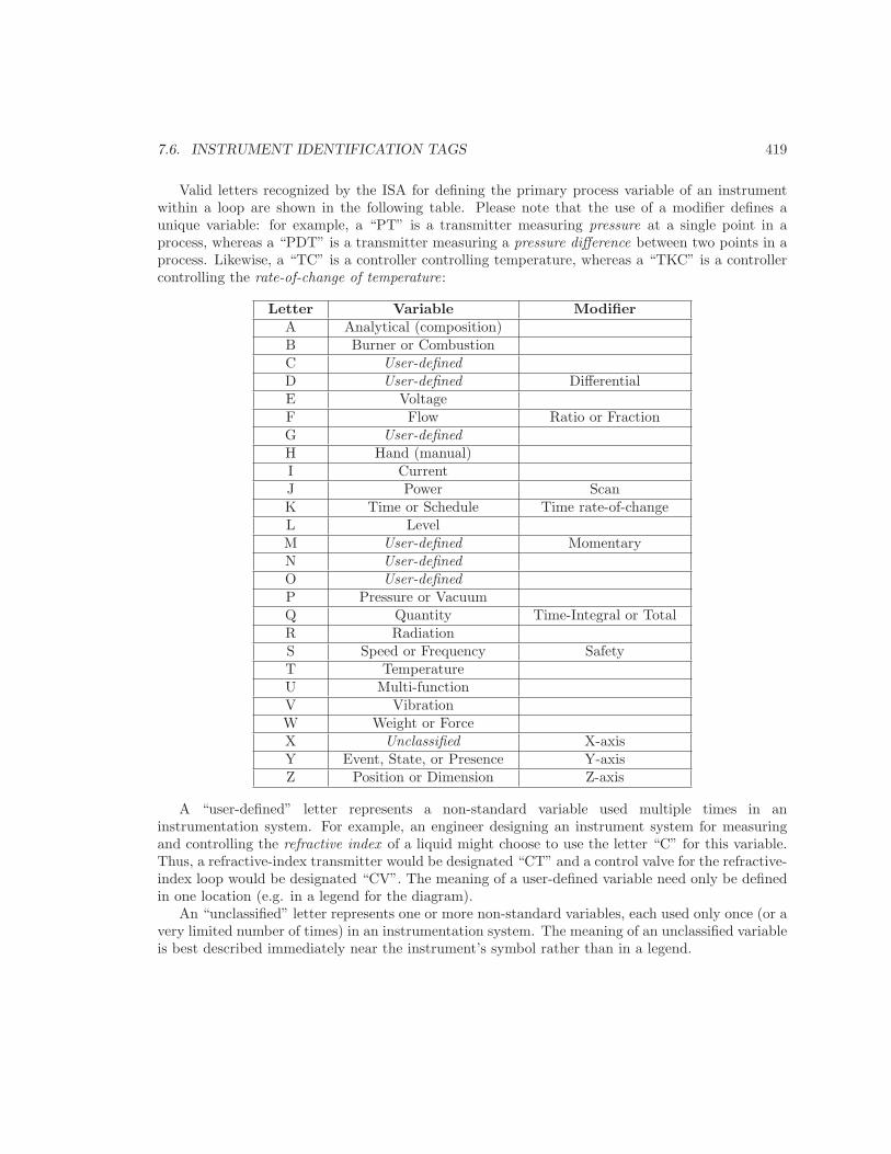
Valid letters recognized by the ISA for defining the primary process variable of an instrumentwithin a loop are shown in the following table. Please note that the use of a modifier defines aunique variable: for example, a “PT” is a transmitter measuring pressure at a single point in aprocess, whereas a “PDT” is a transmitter measuring a pressure difference between two points in aprocess. Likewise, a “TC” is a controller controlling temperature, whereas a “TKC” is a controllercontrolling the rate-of-change of temperature:
Letter Variable ModifierA Analytical (composition)B Burner or CombustionC User-definedD User-defined DifferentialE VoltageF Flow Ratio or FractionG User-definedH Hand (manual)I CurrentJ Power ScanK Time or Schedule Time rate-of-changeL LevelM User-defined MomentaryN User-definedO User-definedP Pressure or VacuumQ Quantity Time-Integral or TotalR RadiationS Speed or Frequency SafetyT TemperatureU Multi-functionV VibrationW Weight or ForceX Unclassified X-axisY Event, State, or Presence Y-axisZ Position or Dimension Z-axis
A “user-defined” letter represents a non-standard variable used multiple times in aninstrumentation system. For example, an engineer designing an instrument system for measuringand controlling the refractive index of a liquid might choose to use the letter “C” for this variable.Thus, a refractive-index transmitter would be designated “CT” and a control valve for the refractive-index loop would be designated “CV”. The meaning of a user-defined variable need only be definedin one location (e.g. in a legend for the diagram).
An “unclassified” letter represents one or more non-standard variables, each used only once (or avery limited number of times) in an instrumentation system. The meaning of an unclassified variableis best described immediately near the instrument’s symbol rather than in a legend.
420 CHAPTER 7. INSTRUMENTATION DOCUMENTS
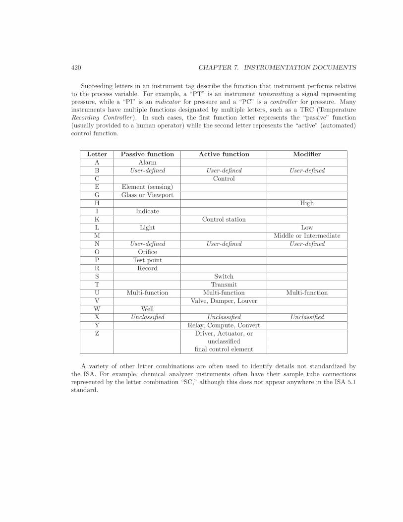
Succeeding letters in an instrument tag describe the function that instrument performs relativeto the process variable. For example, a “PT” is an instrument transmitting a signal representingpressure, while a “PI” is an indicator for pressure and a “PC” is a controller for pressure. Manyinstruments have multiple functions designated by multiple letters, such as a TRC (TemperatureRecording Controller). In such cases, the first function letter represents the “passive” function(usually provided to a human operator) while the second letter represents the “active” (automated)control function.
Letter Passive function Active function ModifierA AlarmB User-defined User-defined User-definedC ControlE Element (sensing)G Glass or ViewportH HighI IndicateK Control stationL Light LowM Middle or IntermediateN User-defined User-defined User-definedO OrificeP Test pointR RecordS SwitchT TransmitU Multi-function Multi-function Multi-functionV Valve, Damper, LouverW WellX Unclassified Unclassified UnclassifiedY Relay, Compute, ConvertZ Driver, Actuator, or
unclassifiedfinal control element
A variety of other letter combinations are often used to identify details not standardized bythe ISA. For example, chemical analyzer instruments often have their sample tube connectionsrepresented by the letter combination “SC,” although this does not appear anywhere in the ISA 5.1standard.
7.6. INSTRUMENT IDENTIFICATION TAGS 421
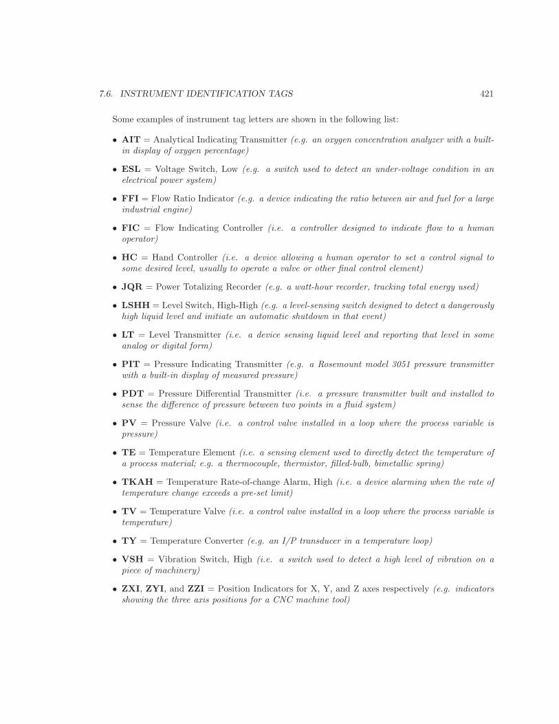
Some examples of instrument tag letters are shown in the following list:
• AIT = Analytical Indicating Transmitter (e.g. an oxygen concentration analyzer with a built-in display of oxygen percentage)
• ESL = Voltage Switch, Low (e.g. a switch used to detect an under-voltage condition in anelectrical power system)
• FFI = Flow Ratio Indicator (e.g. a device indicating the ratio between air and fuel for a largeindustrial engine)
• FIC = Flow Indicating Controller (i.e. a controller designed to indicate flow to a humanoperator)
• HC = Hand Controller (i.e. a device allowing a human operator to set a control signal tosome desired level, usually to operate a valve or other final control element)
• JQR = Power Totalizing Recorder (e.g. a watt-hour recorder, tracking total energy used)
• LSHH = Level Switch, High-High (e.g. a level-sensing switch designed to detect a dangerouslyhigh liquid level and initiate an automatic shutdown in that event)
• LT = Level Transmitter (i.e. a device sensing liquid level and reporting that level in someanalog or digital form)
• PIT = Pressure Indicating Transmitter (e.g. a Rosemount model 3051 pressure transmitterwith a built-in display of measured pressure)
• PDT = Pressure Differential Transmitter (i.e. a pressure transmitter built and installed tosense the difference of pressure between two points in a fluid system)
• PV = Pressure Valve (i.e. a control valve installed in a loop where the process variable ispressure)
• TE = Temperature Element (i.e. a sensing element used to directly detect the temperature ofa process material; e.g. a thermocouple, thermistor, filled-bulb, bimetallic spring)
• TKAH = Temperature Rate-of-change Alarm, High (i.e. a device alarming when the rate oftemperature change exceeds a pre-set limit)
• TV = Temperature Valve (i.e. a control valve installed in a loop where the process variable istemperature)
• TY = Temperature Converter (e.g. an I/P transducer in a temperature loop)
• VSH = Vibration Switch, High (i.e. a switch used to detect a high level of vibration on apiece of machinery)
• ZXI, ZYI, and ZZI = Position Indicators for X, Y, and Z axes respectively (e.g. indicatorsshowing the three axis positions for a CNC machine tool)
422 CHAPTER 7. INSTRUMENTATION DOCUMENTS
References
ANSI/ISA-5.1-2009, Instrumentation Symbols and Identification, Research Triangle Park, NC, 2009.
“Commonly Used Electrical Symbols”, Eaton Electrical Inc., Eaton Corporation, Moon Township,PA, 2005.
Instrumentation, Systems, and Automation Society Standards, 5.1-1984 (R1992), InstrumentationSymbols and Identification, Research Triangle Park, NC, 1984.
Liptak, Bela G. et al., Instrument Engineers’ Handbook – Process Measurement and Analysis VolumeI, Fourth Edition, CRC Press, New York, NY, 2003.
Liptak, Bela G. et al., Instrument Engineers’ Handbook – Process Software and Digital Networks,Third Edition, CRC Press, New York, NY, 2002.
Appendix E
Contributors
This is an open-source book, which means everyone has a legal write to modify it to their liking. Asthe author, I freely accept input from readers that will make this book better. This appendix existsto give credit to those readers who have made substantial contributions to this book.
Sadly, this list does not show the names of every person who has helped me identify and correctminor typographical and grammatical errors. The list of names and errors would be quite substantial,I must admit. Those persons who are listed for their identification of typographical errors haveearned a place on the list through sheer volume of errors found. I am indebted to my students, andto readers around the world for their keen observation and careful reading of the text.
2683
2684 APPENDIX E. CONTRIBUTORS
E.1 Error corrections
Brown, Kevin (February 2011)
• Identified typographical error in the Control Valves chapter.
Esher, Cynthia A. (December 2009)
• Identified error of referring to “SAMA” diagrams. I changed these references to “functional”diagrams instead (Instrumentation Documents chapter).
Glundberg, Blake (February 2011, April 2011)
• Identified typographical errors (Control Valves chapter, Digital Data Acquisition and Networkschapter).
Mhyre, Phil (January 2012)
• Identified spelling error on the word “desiccant” (Discrete Control Elements chapter).
Sangani, Champa (September 2009) and Brainard, Ben (January 2012)
• Identified calculation error in milliamp-to-pH scaling problem (Analog ElectronicInstrumentation chapter).
Schultz, Steven (February 2011)
• Identified error in a pilot-loaded pressure regulator design depicted in the Control Valveschapter.
Thompson, Brice (June 2009)
• Identified errors in high/low select and high/low limit function illustrations (Basic ProcessControl Strategies chapter).
Tsiporenko, Michael (June 2009)
• Identified typographical error in the Introduction to Industrial Instrumentation chapter.
Villajulca, Jose Carlos (August 2011)
• Identified error in PID tuning response for a “generic” simulated process in the ProcessDynamics and PID Controller Tuning chapter.
E.2. NEW CONTENT 2685
E.2 New content
Dennis, Japheth (2011-2012 academic year)
• Suggested additional examples of PID controller responses to graph, to help illustrate theunique features of each action.
Goertz, Kevin (2006-2007 academic year)
• Took photographs of various flowmeters, control valves, and an insertion pH probe assembly.
Poelma, John (2010-2011 academic year)
• Took photographs of various pressure vessels, instruments, control valves, and other processhardware at NASA’s Stennis Space Center in Mississippi.

2686 APPENDIX E. CONTRIBUTORS
Appendix F
Creative Commons AttributionLicense
2687
2688 APPENDIX F. CREATIVE COMMONS ATTRIBUTION LICENSE
F.1 A simple explanation of your rights
This is an “open-source” textbook, meaning the digital files used to create the final form (PDF,printed paper, or other) are freely available for your perusal, reproduction, distribution, and evenmodification. These files reside at the following website:
http://openbookproject.net/books/socratic/sinst/book/
The Creative Commons Attribution license grants you (the recipient), as well as anyone whomight receive my work from you, the right to freely use it. This license also grants you (andothers) the right to modify my work, so long as you properly credit my original authorship. Mywork is copyrighted under United States law, but this license grants everyone else in the worldcertain freedoms not customarily available under full copyright. This means no one needs to ask mypermission, or pay any royalties to me, in order to read, copy, distribute, publish, or otherwise usethis book.
If you choose to modify my work, you will have created what legal professionals refer to as aderivative work. The Creative Commons license broadly groups derivative works under the termadaptations. In simple terms, the fundamental restriction placed on you when you do this is youmust properly credit me for the portions of your adaptation that are my original work. Otherwise,you may treat your adaptation the same way you would treat a completely original work of yourown. This means you are legally permitted to enjoy full copyright protection for your adaptation, upto and including exclusive rights of reproduction and distribution. In other words, this license doesnot bind your derivative work under the same terms and conditions I used to release my originalwork.
The practical upshot of this is you may modify my work and re-publish it as you would anyother book, with the full legal right to demand royalties, restrict distributions, etc. This does notcompromise the freedom of my original work, because that is still available to everyone under theterms and conditions of the Attribution license1. It does, however, protect the investment(s) youmake in creating the adaptation by allowing you to release the adaptation under whatever termsyou see fit (so long as those terms comply with current intellectual property laws, of course).
In summary, the following “legalese” is actually a very good thing for you, the reader of my book.It grants you permission to do so much more with this text than what you would be legally allowedto do with any other (traditionally copyrighted) book. It also opens the door to open collaborativedevelopment, so it might grow into something far better than what I alone could create.
1You cannot pass my original work to anyone else under different terms or conditions than the Attribution license.That is called sublicensing, and the Attribution license forbids it. In fact, any re-distribution of my original workmust come with a notice to the Attribution license, so anyone receiving the book through you knows their rights.
F.2. LEGAL CODE 2689
F.2 Legal code
THE WORK (AS DEFINED BELOW) IS PROVIDED UNDER THE TERMS OF THISCREATIVE COMMONS PUBLIC LICENSE (“CCPL” OR “LICENSE”). THE WORK ISPROTECTED BY COPYRIGHT AND/OR OTHER APPLICABLE LAW. ANY USE OF THEWORK OTHER THAN AS AUTHORIZED UNDER THIS LICENSE OR COPYRIGHT LAW ISPROHIBITED.
BY EXERCISING ANY RIGHTS TO THE WORK PROVIDED HERE, YOU ACCEPT ANDAGREE TO BE BOUND BY THE TERMS OF THIS LICENSE. TO THE EXTENT THISLICENSE MAY BE CONSIDERED TO BE A CONTRACT, THE LICENSOR GRANTS YOUTHE RIGHTS CONTAINED HERE IN CONSIDERATION OF YOUR ACCEPTANCE OF SUCHTERMS AND CONDITIONS.
1. Definitions1. “Adaptation” means a work based upon the Work, or upon the Work and other pre-existing
works, such as a translation, adaptation, derivative work, arrangement of music or other alterationsof a literary or artistic work, or phonogram or performance and includes cinematographic adaptationsor any other form in which the Work may be recast, transformed, or adapted including in any formrecognizably derived from the original, except that a work that constitutes a Collection will notbe considered an Adaptation for the purpose of this License. For the avoidance of doubt, wherethe Work is a musical work, performance or phonogram, the synchronization of the Work in timed-relation with a moving image (“synching”) will be considered an Adaptation for the purpose of thisLicense.
2. “Collection” means a collection of literary or artistic works, such as encyclopedias andanthologies, or performances, phonograms or broadcasts, or other works or subject matter otherthan works listed in Section 1(f) below, which, by reason of the selection and arrangement of theircontents, constitute intellectual creations, in which the Work is included in its entirety in unmodifiedform along with one or more other contributions, each constituting separate and independent worksin themselves, which together are assembled into a collective whole. A work that constitutes aCollection will not be considered an Adaptation (as defined above) for the purposes of this License.
3. “Distribute” means to make available to the public the original and copies of the Work orAdaptation, as appropriate, through sale or other transfer of ownership.
4. “Licensor” means the individual, individuals, entity or entities that offer(s) the Work underthe terms of this License.
5. “Original Author” means, in the case of a literary or artistic work, the individual, individuals,entity or entities who created the Work or if no individual or entity can be identified, the publisher;and in addition (i) in the case of a performance the actors, singers, musicians, dancers, and otherpersons who act, sing, deliver, declaim, play in, interpret or otherwise perform literary or artisticworks or expressions of folklore; (ii) in the case of a phonogram the producer being the person orlegal entity who first fixes the sounds of a performance or other sounds; and, (iii) in the case ofbroadcasts, the organization that transmits the broadcast.
6. “Work” means the literary and/or artistic work offered under the terms of this Licenseincluding without limitation any production in the literary, scientific and artistic domain, whatevermay be the mode or form of its expression including digital form, such as a book, pamphlet andother writing; a lecture, address, sermon or other work of the same nature; a dramatic or dramatico-musical work; a choreographic work or entertainment in dumb show; a musical composition with
2690 APPENDIX F. CREATIVE COMMONS ATTRIBUTION LICENSE
or without words; a cinematographic work to which are assimilated works expressed by a processanalogous to cinematography; a work of drawing, painting, architecture, sculpture, engraving orlithography; a photographic work to which are assimilated works expressed by a process analogousto photography; a work of applied art; an illustration, map, plan, sketch or three-dimensional workrelative to geography, topography, architecture or science; a performance; a broadcast; a phonogram;a compilation of data to the extent it is protected as a copyrightable work; or a work performed bya variety or circus performer to the extent it is not otherwise considered a literary or artistic work.
7. “You” means an individual or entity exercising rights under this License who has not previouslyviolated the terms of this License with respect to the Work, or who has received express permissionfrom the Licensor to exercise rights under this License despite a previous violation.
8. “Publicly Perform” means to perform public recitations of the Work and to communicate tothe public those public recitations, by any means or process, including by wire or wireless meansor public digital performances; to make available to the public Works in such a way that membersof the public may access these Works from a place and at a place individually chosen by them; toperform the Work to the public by any means or process and the communication to the public of theperformances of the Work, including by public digital performance; to broadcast and rebroadcastthe Work by any means including signs, sounds or images.
9. “Reproduce” means to make copies of the Work by any means including without limitation bysound or visual recordings and the right of fixation and reproducing fixations of the Work, includingstorage of a protected performance or phonogram in digital form or other electronic medium.
2. Fair Dealing Rights. Nothing in this License is intended to reduce, limit, or restrict anyuses free from copyright or rights arising from limitations or exceptions that are provided for inconnection with the copyright protection under copyright law or other applicable laws.
3. License Grant. Subject to the terms and conditions of this License, Licensor hereby grantsYou a worldwide, royalty-free, non-exclusive, perpetual (for the duration of the applicable copyright)license to exercise the rights in the Work as stated below:
1. to Reproduce the Work, to incorporate the Work into one or more Collections, and toReproduce the Work as incorporated in the Collections;
2. to create and Reproduce Adaptations provided that any such Adaptation, including anytranslation in any medium, takes reasonable steps to clearly label, demarcate or otherwise identifythat changes were made to the original Work. For example, a translation could be marked “Theoriginal work was translated from English to Spanish,” or a modification could indicate “The originalwork has been modified.”;
3. to Distribute and Publicly Perform the Work including as incorporated in Collections; and,4. to Distribute and Publicly Perform Adaptations.5. For the avoidance of doubt:
1. Non-waivable Compulsory License Schemes. In those jurisdictions in which the right tocollect royalties through any statutory or compulsory licensing scheme cannot be waived, the Licensorreserves the exclusive right to collect such royalties for any exercise by You of the rights grantedunder this License;
2. Waivable Compulsory License Schemes. In those jurisdictions in which the right to collectroyalties through any statutory or compulsory licensing scheme can be waived, the Licensor waivesthe exclusive right to collect such royalties for any exercise by You of the rights granted under thisLicense; and,
F.2. LEGAL CODE 2691
3. Voluntary License Schemes. The Licensor waives the right to collect royalties, whetherindividually or, in the event that the Licensor is a member of a collecting society that administersvoluntary licensing schemes, via that society, from any exercise by You of the rights granted underthis License.
The above rights may be exercised in all media and formats whether now known or hereafterdevised. The above rights include the right to make such modifications as are technically necessaryto exercise the rights in other media and formats. Subject to Section 8(f), all rights not expresslygranted by Licensor are hereby reserved.
4. Restrictions. The license granted in Section 3 above is expressly made subject to and limitedby the following restrictions:
1. You may Distribute or Publicly Perform the Work only under the terms of this License. Youmust include a copy of, or the Uniform Resource Identifier (URI) for, this License with every copy ofthe Work You Distribute or Publicly Perform. You may not offer or impose any terms on the Workthat restrict the terms of this License or the ability of the recipient of the Work to exercise the rightsgranted to that recipient under the terms of the License. You may not sublicense the Work. Youmust keep intact all notices that refer to this License and to the disclaimer of warranties with everycopy of the Work You Distribute or Publicly Perform. When You Distribute or Publicly Performthe Work, You may not impose any effective technological measures on the Work that restrict theability of a recipient of the Work from You to exercise the rights granted to that recipient underthe terms of the License. This Section 4(a) applies to the Work as incorporated in a Collection,but this does not require the Collection apart from the Work itself to be made subject to the termsof this License. If You create a Collection, upon notice from any Licensor You must, to the extentpracticable, remove from the Collection any credit as required by Section 4(b), as requested. If Youcreate an Adaptation, upon notice from any Licensor You must, to the extent practicable, removefrom the Adaptation any credit as required by Section 4(b), as requested.
2. If You Distribute, or Publicly Perform the Work or any Adaptations or Collections, Youmust, unless a request has been made pursuant to Section 4(a), keep intact all copyright noticesfor the Work and provide, reasonable to the medium or means You are utilizing: (i) the name ofthe Original Author (or pseudonym, if applicable) if supplied, and/or if the Original Author and/orLicensor designate another party or parties (e.g., a sponsor institute, publishing entity, journal)for attribution (“Attribution Parties”) in Licensor’s copyright notice, terms of service or by otherreasonable means, the name of such party or parties; (ii) the title of the Work if supplied; (iii)to the extent reasonably practicable, the URI, if any, that Licensor specifies to be associated withthe Work, unless such URI does not refer to the copyright notice or licensing information for theWork; and (iv) , consistent with Section 3(b), in the case of an Adaptation, a credit identifying theuse of the Work in the Adaptation (e.g., “French translation of the Work by Original Author,” or“Screenplay based on original Work by Original Author”). The credit required by this Section 4 (b)may be implemented in any reasonable manner; provided, however, that in the case of a Adaptationor Collection, at a minimum such credit will appear, if a credit for all contributing authors of theAdaptation or Collection appears, then as part of these credits and in a manner at least as prominentas the credits for the other contributing authors. For the avoidance of doubt, You may only use thecredit required by this Section for the purpose of attribution in the manner set out above and, byexercising Your rights under this License, You may not implicitly or explicitly assert or imply anyconnection with, sponsorship or endorsement by the Original Author, Licensor and/or AttributionParties, as appropriate, of You or Your use of the Work, without the separate, express prior written
2692 APPENDIX F. CREATIVE COMMONS ATTRIBUTION LICENSE
permission of the Original Author, Licensor and/or Attribution Parties.
3. Except as otherwise agreed in writing by the Licensor or as may be otherwise permittedby applicable law, if You Reproduce, Distribute or Publicly Perform the Work either by itself oras part of any Adaptations or Collections, You must not distort, mutilate, modify or take otherderogatory action in relation to the Work which would be prejudicial to the Original Author’s honoror reputation. Licensor agrees that in those jurisdictions (e.g. Japan), in which any exercise ofthe right granted in Section 3(b) of this License (the right to make Adaptations) would be deemedto be a distortion, mutilation, modification or other derogatory action prejudicial to the OriginalAuthor’s honor and reputation, the Licensor will waive or not assert, as appropriate, this Section,to the fullest extent permitted by the applicable national law, to enable You to reasonably exerciseYour right under Section 3(b) of this License (right to make Adaptations) but not otherwise.
5. Representations, Warranties and Disclaimer
UNLESS OTHERWISE MUTUALLY AGREEDTO BY THE PARTIES IN WRITING, LICENSOR OFFERS THE WORK AS-IS AND MAKESNO REPRESENTATIONS OR WARRANTIES OF ANY KIND CONCERNING THE WORK,EXPRESS, IMPLIED, STATUTORY OR OTHERWISE, INCLUDING, WITHOUT LIMITATION,WARRANTIES OF TITLE, MERCHANTABILITY, FITNESS FOR A PARTICULAR PURPOSE,NONINFRINGEMENT, OR THE ABSENCE OF LATENT OR OTHER DEFECTS, ACCURACY,OR THE PRESENCE OF ABSENCE OF ERRORS, WHETHER OR NOT DISCOVERABLE.SOME JURISDICTIONS DO NOT ALLOW THE EXCLUSION OF IMPLIED WARRANTIES,SO SUCH EXCLUSION MAY NOT APPLY TO YOU.
6. Limitation on Liability. EXCEPT TO THE EXTENT REQUIRED BY APPLICABLELAW, IN NO EVENT WILL LICENSOR BE LIABLE TO YOU ON ANY LEGAL THEORY FORANY SPECIAL, INCIDENTAL, CONSEQUENTIAL, PUNITIVE OR EXEMPLARY DAMAGESARISING OUT OF THIS LICENSE OR THE USE OF THE WORK, EVEN IF LICENSOR HASBEEN ADVISED OF THE POSSIBILITY OF SUCH DAMAGES.
7. Termination
1. This License and the rights granted hereunder will terminate automatically upon any breachby You of the terms of this License. Individuals or entities who have received Adaptations orCollections from You under this License, however, will not have their licenses terminated providedsuch individuals or entities remain in full compliance with those licenses. Sections 1, 2, 5, 6, 7, and8 will survive any termination of this License.
2. Subject to the above terms and conditions, the license granted here is perpetual (for theduration of the applicable copyright in the Work). Notwithstanding the above, Licensor reservesthe right to release the Work under different license terms or to stop distributing the Work at anytime; provided, however that any such election will not serve to withdraw this License (or any otherlicense that has been, or is required to be, granted under the terms of this License), and this Licensewill continue in full force and effect unless terminated as stated above.
8. Miscellaneous
1. Each time You Distribute or Publicly Perform the Work or a Collection, the Licensor offersto the recipient a license to the Work on the same terms and conditions as the license granted toYou under this License.
F.2. LEGAL CODE 2693
2. Each time You Distribute or Publicly Perform an Adaptation, Licensor offers to the recipienta license to the original Work on the same terms and conditions as the license granted to You underthis License.
3. If any provision of this License is invalid or unenforceable under applicable law, it shall notaffect the validity or enforceability of the remainder of the terms of this License, and without furtheraction by the parties to this agreement, such provision shall be reformed to the minimum extentnecessary to make such provision valid and enforceable.
4. No term or provision of this License shall be deemed waived and no breach consented to unlesssuch waiver or consent shall be in writing and signed by the party to be charged with such waiveror consent.
5. This License constitutes the entire agreement between the parties with respect to the Worklicensed here. There are no understandings, agreements or representations with respect to the Worknot specified here. Licensor shall not be bound by any additional provisions that may appear in anycommunication from You. This License may not be modified without the mutual written agreementof the Licensor and You.
6. The rights granted under, and the subject matter referenced, in this License were draftedutilizing the terminology of the Berne Convention for the Protection of Literary and Artistic Works(as amended on September 28, 1979), the Rome Convention of 1961, the WIPO Copyright Treatyof 1996, the WIPO Performances and Phonograms Treaty of 1996 and the Universal CopyrightConvention (as revised on July 24, 1971). These rights and subject matter take effect in the relevantjurisdiction in which the License terms are sought to be enforced according to the correspondingprovisions of the implementation of those treaty provisions in the applicable national law. If thestandard suite of rights granted under applicable copyright law includes additional rights not grantedunder this License, such additional rights are deemed to be included in the License; this License isnot intended to restrict the license of any rights under applicable law.
Creative Commons NoticeCreative Commons is not a party to this License, and makes no warranty whatsoever in
connection with the Work. Creative Commons will not be liable to You or any party on any legaltheory for any damages whatsoever, including without limitation any general, special, incidental orconsequential damages arising in connection to this license. Notwithstanding the foregoing two (2)sentences, if Creative Commons has expressly identified itself as the Licensor hereunder, it shall haveall rights and obligations of Licensor.
Except for the limited purpose of indicating to the public that the Work is licensed under theCCPL, Creative Commons does not authorize the use by either party of the trademark “CreativeCommons” or any related trademark or logo of Creative Commons without the prior written consentof Creative Commons. Any permitted use will be in compliance with Creative Commons’ then-current trademark usage guidelines, as may be published on its website or otherwise made availableupon request from time to time. For the avoidance of doubt, this trademark restriction does notform part of this License.
Creative Commons may be contacted at http://creativecommons.org/