instructions schmidt & bender zenith 1.5-6x42 | optics trade
TRANSCRIPT
Operating Manual
1.5-6x42 Zenith Page 1 of 16
Schmidt & Bender GmbH & Co. KG • Am Grossacker 42 • D-35444 Biebertal
Tel. +49 (0) 64 09-81 15-0 • Fax +49 (0) 64 09-81 15-11 [email protected] • www.schmidt-bender.de
1.5-6x42 Zenith

Operating Manual
1.5-6x42 Zenith Page 3 of 16
Schmidt & Bender GmbH & Co. KG • Am Grossacker 42 • D-35444 Biebertal Tel. +49 (0) 64 09-81 15-0 • Fax +49 (0) 64 09-81 15-11 [email protected] • www.schmidt-bender.de
1. Scope description .......................................................................................... 4 1.1 Introduction ............................................................................................... 4
1.2 Safety instructions ..................................................................................... 4
2. Technical data ............................................................................................... 5 2.1 General data ............................................................................................. 5
2.2 Dimensions ................................................................................................. 5
3. Accessories / Scope of supply ..................................................................... 6
4. Operating instructions ................................................................................... 6 4.1 Adjusting the image focus with the diopter adjustment of the eyepiece .................................................................................................................. 7
4.2 Illumination Control................................................................................... 7
4.3 Changing the battery .............................................................................. 8
5. Preliminary adjusting and fine adjusting when sighting in ...................... 10 5.1 Using the Posicon turrets ........................................................................ 10
5.2 Elevation adjustment ............................................................................. 12
5.3 Windage adjustment ............................................................................. 12
5.4 Marking the zero position ...................................................................... 13
6. Care and maintenance .............................................................................. 13 7. Storage temperature ................................................................................... 14 8. Warranty certificate ..................................................................................... 15
Operating Manual
1.5-6x42 Zenith Page 4 of 16
Schmidt & Bender GmbH & Co. KG • Am Grossacker 42 • D-35444 Biebertal Tel. +49 (0) 64 09-81 15-0 • Fax +49 (0) 64 09-81 15-11 [email protected] • www.schmidt-bender.de
1. Scope description
1.1 Introduction
The Schmidt & Bender Zenith hunting scopes are designed to meet the unique challenges of high precision shooting. Their quality and function make it possible to achieve exceptional shooting results as well as to fulfill the critical and demanding needs of official, law enforcement and tactical applications. Strict observation of the following operating instructions is prerequisite for successful long-term use.
1.2 Safety instructions
Never look into the sun or into laser light with the scope. This may cause serious eye injuries. Do not tamper with the scope. Any repairs beyond the maintenance described in the maintenance manual should only be performed by Schmidt & Bender or by other specialists authorized by Schmidt & Bender. Protect the scope against shocks beyond normal use. Avoid unnecessary long exposure of the scope to direct sunlight; intense and excessive sun radiation will cause extremely high temperatures inside the tube which may be detrimental to the scope. The scope must be properly mounted to the firearm by a qualified specialist. Perfect mounting is an essential requirement for maximum accuracy and efficient functioning of the firearm and the scope. Be sure to assume the proper firing position and keep a correct eye relief in order to obtain an optimal full field of view and to avoid any injuries due to the recoil of the weapon.
Operating Manual
1.5-6x42 Zenith Page 5 of 16
Schmidt & Bender GmbH & Co. KG • Am Grossacker 42 • D-35444 Biebertal Tel. +49 (0) 64 09-81 15-0 • Fax +49 (0) 64 09-81 15-11 [email protected] • www.schmidt-bender.de
2. Technical data
2.1 General data
Field of view - 21,7 – 6,7 (m/100m) Exit pupil - 14,4 – 7 (mm) Eye relief - 90 (mm) Twilight factor - 4,2 – 15,9 Transmission - 90 (%) Diopter adjustment - +2 to -3 (dptr) Parallax - fix 100 (m) Reticle focal plane - 1
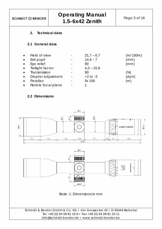
2.2 Dimensions
Illustr. 1: Dimensions in mm
Operating Manual
1.5-6x42 Zenith Page 6 of 16
Schmidt & Bender GmbH & Co. KG • Am Grossacker 42 • D-35444 Biebertal Tel. +49 (0) 64 09-81 15-0 • Fax +49 (0) 64 09-81 15-11 [email protected] • www.schmidt-bender.de
3. Accessories / Scope of supply
The following accessories are delivered with scope and can be reordered at a distributor or our service. Protective Bikini Caps Registration card Reply card
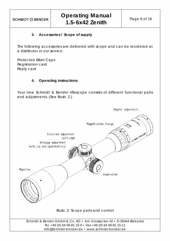
4. Operating instructions
Your new Schmidt & Bender riflescope consists of different functional parts and adjustments. (See Illustr. 2.)
Illustr. 2: Scope parts and control
Operating Manual
1.5-6x42 Zenith Page 7 of 16
Schmidt & Bender GmbH & Co. KG • Am Grossacker 42 • D-35444 Biebertal Tel. +49 (0) 64 09-81 15-0 • Fax +49 (0) 64 09-81 15-11 [email protected] • www.schmidt-bender.de
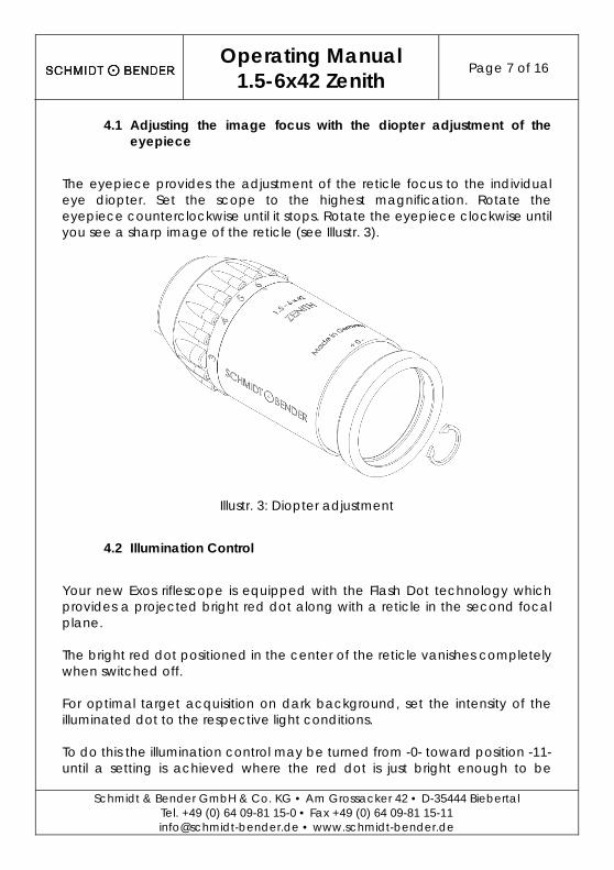
4.1 Adjusting the image focus with the diopter adjustment of the eyepiece
The eyepiece provides the adjustment of the reticle focus to the individual eye diopter. Set the scope to the highest magnification. Rotate the eyepiece counterclockwise until it stops. Rotate the eyepiece clockwise until you see a sharp image of the reticle (see Illustr. 3).
Illustr. 3: Diopter adjustment
4.2 Illumination Control
Your new Exos riflescope is equipped with the Flash Dot technology which provides a projected bright red dot along with a reticle in the second focal plane. The bright red dot positioned in the center of the reticle vanishes completely when switched off. For optimal target acquisition on dark background, set the intensity of the illuminated dot to the respective light conditions. To do this the illumination control may be turned from -0- toward position -11- until a setting is achieved where the red dot is just bright enough to be
Operating Manual
1.5-6x42 Zenith Page 8 of 16
Schmidt & Bender GmbH & Co. KG • Am Grossacker 42 • D-35444 Biebertal Tel. +49 (0) 64 09-81 15-0 • Fax +49 (0) 64 09-81 15-11 [email protected] • www.schmidt-bender.de
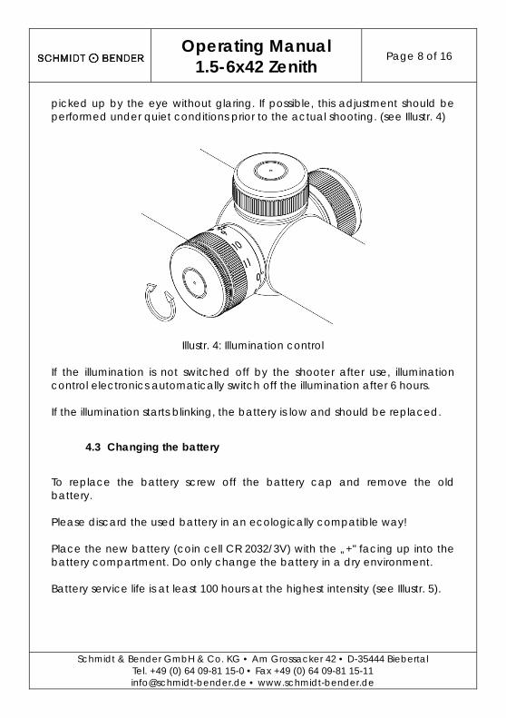
picked up by the eye without glaring. If possible, this adjustment should be performed under quiet conditions prior to the actual shooting. (see Illustr. 4)
Illustr. 4: Illumination control If the illumination is not switched off by the shooter after use, illumination control electronics automatically switch off the illumination after 6 hours. If the illumination starts blinking, the battery is low and should be replaced.
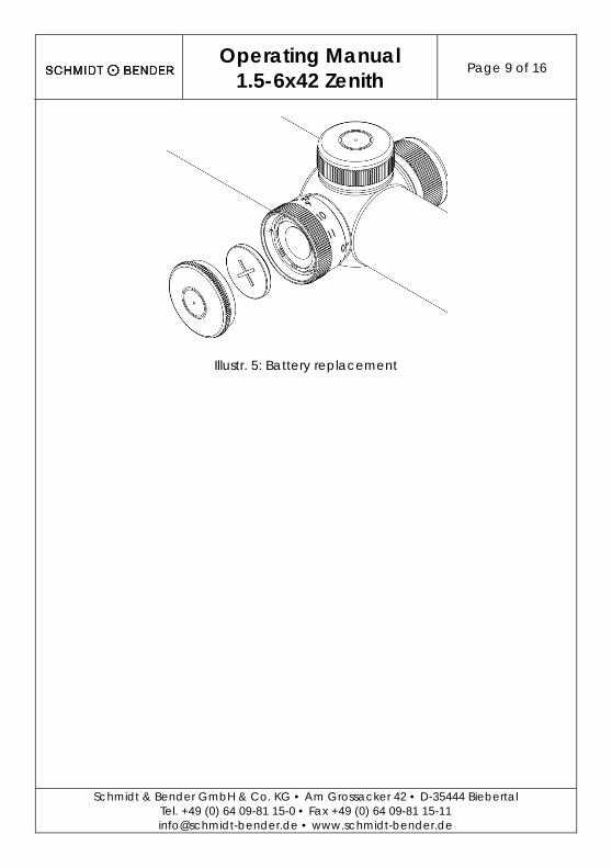
4.3 Changing the battery
To replace the battery screw off the battery cap and remove the old battery. Please discard the used battery in an ecologically compatible way! Place the new battery (coin cell CR 2032/3V) with the „+" facing up into the battery compartment. Do only change the battery in a dry environment. Battery service life is at least 100 hours at the highest intensity (see Illustr. 5).
Operating Manual
1.5-6x42 Zenith Page 9 of 16
Schmidt & Bender GmbH & Co. KG • Am Grossacker 42 • D-35444 Biebertal Tel. +49 (0) 64 09-81 15-0 • Fax +49 (0) 64 09-81 15-11 [email protected] • www.schmidt-bender.de
Illustr. 5: Battery replacement
Operating Manual
1.5-6x42 Zenith Page 10 of 16
Schmidt & Bender GmbH & Co. KG • Am Grossacker 42 • D-35444 Biebertal Tel. +49 (0) 64 09-81 15-0 • Fax +49 (0) 64 09-81 15-11 [email protected] • www.schmidt-bender.de
5. Preliminary adjusting and fine adjusting when sighting in
5.1 Using the Posicon turrets
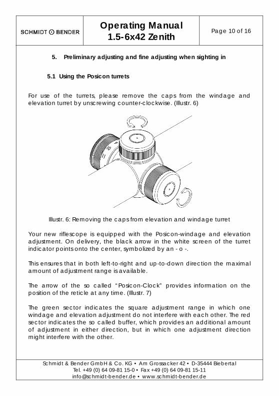
For use of the turrets, please remove the caps from the windage and elevation turret by unscrewing counter-clockwise. (Illustr. 6)
Illustr. 6: Removing the caps from elevation and windage turret Your new riflescope is equipped with the Posicon-windage and elevation adjustment. On delivery, the black arrow in the white screen of the turret indicator points onto the center, symbolized by an - o -. This ensures that in both left-to-right and up-to-down direction the maximal amount of adjustment range is available. The arrow of the so called “Posicon-Clock” provides information on the position of the reticle at any time. (Illustr. 7) The green sector indicates the square adjustment range in which one windage and elevation adjustment do not interfere with each other. The red sector indicates the so called buffer, which provides an additional amount of adjustment in either direction, but in which one adjustment direction might interfere with the other.
Operating Manual
1.5-6x42 Zenith Page 11 of 16
Schmidt & Bender GmbH & Co. KG • Am Grossacker 42 • D-35444 Biebertal Tel. +49 (0) 64 09-81 15-0 • Fax +49 (0) 64 09-81 15-11 [email protected] • www.schmidt-bender.de
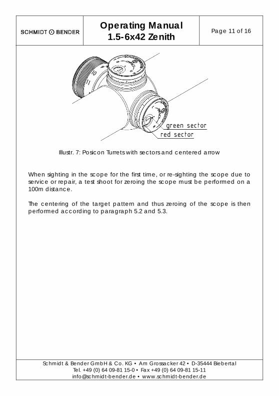
Illustr. 7: Posicon Turrets with sectors and centered arrow When sighting in the scope for the first time, or re-sighting the scope due to service or repair, a test shoot for zeroing the scope must be performed on a 100m distance. The centering of the target pattern and thus zeroing of the scope is then performed according to paragraph 5.2 and 5.3.
Operating Manual
1.5-6x42 Zenith Page 12 of 16
Schmidt & Bender GmbH & Co. KG • Am Grossacker 42 • D-35444 Biebertal Tel. +49 (0) 64 09-81 15-0 • Fax +49 (0) 64 09-81 15-11 [email protected] • www.schmidt-bender.de
5.2 Elevation adjustment
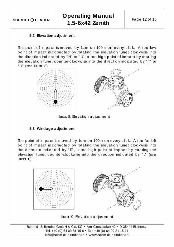
The point of impact is moved by 1cm on 100m on every click. A too low point of impact is corrected by rotating the elevation turret clockwise into the direction indicated by “H” or “U”, a too high point of impact by rotating the elevation turret counter-clockwise into the direction indicated by “T” or “D” (see Illustr. 8).
Illustr. 8: Elevation adjustment
5.3 Windage adjustment
The point of impact is moved by 1cm on 100m on every click. A too far left point of impact is corrected by rotating the elevation turret clockwise into the direction indicated by “R”, a too high point of impact by rotating the elevation turret counter-clockwise into the direction indicated by “L” (see Illustr. 8).
Illustr. 9: Elevation adjustment
Operating Manual
1.5-6x42 Zenith Page 13 of 16
Schmidt & Bender GmbH & Co. KG • Am Grossacker 42 • D-35444 Biebertal Tel. +49 (0) 64 09-81 15-0 • Fax +49 (0) 64 09-81 15-11 [email protected] • www.schmidt-bender.de
5.4 Marking the zero position
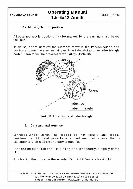
All obtained reticle positions may be marked by the aluminum ring below the knurl. To do so, please unscrew the cross-slot screw in the Posicon screen and position and turn the aluminum ring until the index dot and the index triangle match. Then screw the cross-slot screw tightly. (Illustr. 10)
Illustr. 10: Index ring and index triangle
6. Care and maintenance
Schmidt & Bender Zenith line scopes do not require any special maintenance. All metal parts have a hard anodized surface that is extremely scratch-resistant and easy to care for. For cleaning outer surfaces, use a clean and, if necessary, a slightly damp cloth. For cleaning the optics use the included Schmidt & Bender cleaning kit.
Operating Manual
1.5-6x42 Zenith Page 14 of 16
Schmidt & Bender GmbH & Co. KG • Am Grossacker 42 • D-35444 Biebertal Tel. +49 (0) 64 09-81 15-0 • Fax +49 (0) 64 09-81 15-11 [email protected] • www.schmidt-bender.de
Before wiping the optic’s surfaces, use a dry brush to remove coarse dirt or dust particles. Slight impurities may then be wiped off using an optic’s cleaning cloth. Breathe onto the optic’s surfaces before cleaning them, this helps with the cleaning process. Excessive dirt may be removed using the cleaning liquid included in the cleaning kit. Avoid dry rubbing on the outside optical surfaces, this may harm the precious coatings.
7. Storage temperature
The approved temperature range for the storage of the scope is from -55°C to 70°C.
Operating Manual
1.5-6x42 Zenith Page 15 of 16
Schmidt & Bender GmbH & Co. KG • Am Grossacker 42 • D-35444 Biebertal Tel. +49 (0) 64 09-81 15-0 • Fax +49 (0) 64 09-81 15-11 [email protected] • www.schmidt-bender.de
8. Warranty certificate
We hereby certify that our Quality Management System has been approved by Unternehmensgruppe TUV Rheinland Berlin Brandenburg to the following Quality Management Standard: The TUV Cert Certification Body of TUV Anlagentechnik GmbH (Unternehmensgruppe TUV Rheinland Berlin Brandenburg) certifies in accordance with TUV Cert procedures that Schmidt & Bender GmbH & Co. KG, Am Grossacker 42, D- 35444 Biebertal has established and applies a quality management system for the design, production sales and service of fine mechanical optical instruments. Main product telescopic sights. Proof has been furnished that the requirements according to ISO 9001 – # Registration No. 01 100 67280 - are fulfilled. All parts have been thoroughly inspected in accordance with the afore-mentioned Quality Management System and correspond to the requirements of the specifications, drawings, test procedures and standards in all respects. Guarantee clause:
- Guarantee period of 10 years - Replacement parts are available for at least 30 years
Contact: Schmidt & Bender GmbH & Co. KG • Am Grossacker 42 • D-35444 Biebertal • Germany Tel. +49 (0) 64 09-81 15-0 • Fax +49 (0) 64 09-81 15-11 [email protected] • www.schmidt-bender.de Schmidt & Bender Inc. • 741 Main Street • Claremont, NH 03743 • U.S.A. Tollfree (800)468-3450 • Phone +1(603)287-4830 • Fax (603)287-4832 [email protected]

Schmidt & Bender GmbH & Co. KG • Am Grossacker 42 • D-35444 Biebertal Tel. +49 (0) 64 09-81 15-0 • Fax +49 (0) 64 09-81 15-11 [email protected] • www.schmidt-bender.de
Subject to changes, Date 15.05.2014, Revision 00