instruction manual model 1221 distillation probe...the model 1221 distillation probe utilizes a...
TRANSCRIPT

MAN.1221.REVD.092017
Instruction Manual
Model 1221 Distillation Probe
5200 Convair Drive • Carson City, NV 89706 • Ph: 775.883.2500 • Fax: 775.883.6388 • www.universalanalyzers.com

MAN.1221.REVD.092017 Page 2 of 34
TABLE OF CONTENTS
1.0 Notice ................................................................................................................. 1-3
2.0 Definition of Symbols .......................................................................................... 2-4
3.0 Theory of Operation............................................................................................ 3-5
4.0 Installation .......................................................................................................... 4-8
4.1 Utilities ........................................................................................................................................ 4-8
5.0 Probe Controllers ............................................................................................... 5-9
5.1 Pneumatic Controllers ................................................................................................................ 5-9
5.1.1 Pneumatic Controller Layouts ............................................................................................ 5-9
5.1.2 Pneumatic Controller Operation ....................................................................................... 5-11
5.2 Electronic Controllers ............................................................................................................... 5-12
5.2.1 Electronic Controller Layouts ........................................................................................... 5-12
5.2.2 Electronic Controller Overview ......................................................................................... 5-15
5.2.3 HMI Display and Operation .............................................................................................. 5-16
5.2.4 Network and Status Display ............................................................................................. 5-17
5.2.5 Primary Temperature Screen ........................................................................................... 5-17
5.2.6 Sample Isolation Valve Manual Operation Screen .......................................................... 5-18
5.2.7 Sample Temperature Setpoints Screen ........................................................................... 5-19
5.2.8 Process Temperature Setpoints Screen .......................................................................... 5-20
5.2.9 Coolant Dwell Timer Operation Screen ........................................................................... 5-21
5.2.10 Enclosure Temperature Screen ....................................................................................... 5-23
5.2.11 Factory Default Values Screen ........................................................................................ 5-23
5.2.12 Changing IP Address and Slave Number ........................................................................ 5-24
5.2.13 Modbus ............................................................................................................................. 5-26
6.0 Start-Up ............................................................................................................ 6-28
7.0 Maintenance ..................................................................................................... 7-29
8.0 Troubleshooting ................................................................................................ 8-30
9.0 Spare Parts ...................................................................................................... 9-31
10.0 Drawings ........................................................................................................ 10-32
11.0 Limited Warranty ............................................................................................ 11-33
MAN.1221.REVD.092017 Page 3 of 34
1.0 Notice
This equipment is designed for industrial analytical applications. Individual installations may vary in scope. The installer should consult national, local, and plant construction codes to ensure that governing regulations are met.
When installing optional electronic control equipment, as a minimum, general installation precautions should be observed:
Select a site that is free from direct sunlight, high temperature, or abrupt temperature variations. Select a site where the air is free from corrosive gases, or abrasive materials. The equipment should not be subjected to severe vibration. Protective mounts should be installed to
isolate the equipment from excessive vibration.
Do not install analyzer near equipment emitting electromagnetic interference. Electrical wiring should be installed according to the National Electrical Code and/or any other
applicable local codes and regulations. Supply voltage should strictly adhere to the instrument specifications, be supplied from a stable,
reliable source, and provided with proper ground connections. Signal connections should be made using shielded wiring. Signal, control, and interface wiring should be located separately from power supply lines.
Analyzer documentation should be consulted to determine sample transport options.

MAN.1221.REVD.092017 Page 4 of 34
2.0 Definition of Symbols
CAUTION, RISK OF DANGER SYMBOL INDICATES INJURY MAY OCCUR IF MANUFACTURER’S
INSTRUCTIONS ARE NOT ADHERED TO. PLEASE READ MANUAL CAREFULLY WHEN SYMBOL IS DISPLAYED
CAUTION, HOT SURFACE SYMBOL INDICATES EXPOSED SURFACE TEMPERATURE CAN
CAUSE BURNS OR PERSONAL INJURY. CARE SHOULD BE TAKEN WHEN CONTACT IS REQUIRED.
CAUTION, RISK OF ELECTRICAL SHOCK SYMBOL INDICATES ELECTRICAL SHOCK MAY OCCUR. CAUTION SHOULD BE TAKEN BEFORE DISCONNECTING OR CONTACTING ANY
ELECTRICAL CONNECTIONS.
PROTECTIVE CONDUCTOR TERMINAL SYMBOL INDICATES THE TERMINAL LOCATION FOR THE PROTECTIVE CONDUCTOR. FAILURE TO CONNECT TO THE PROTECTIVE CONDUCTOR
TERMINAL MAY RESULT IN A SHOCK HAZARD.

MAN.1221.REVD.092017 Page 5 of 34
3.0 Theory of Operation All ethylene production facilities will employ some type of cracking furnace, which is used to convert saturated hydrocarbons found in the feed stock into unsaturated hydrocarbons or olefins, which are the basic building blocks used in a variety of chemicals produced downstream of the olefins plant. The process of cracking involves taking a gas feed stock such as 80% ethane / 20% propane or a light liquid hydrocarbon feedstock, and then diluting it with steam, which then heats it rapidly to 750–950°C. During this process, two hydrogen atoms are removed from ethane (C2H6) and propane (C3H8) resulting in the formation of ethylene (C2H4) and propylene (C3H6). In a typical cracking furnace, the residence time is reduced to milliseconds to improve yield, resulting in very high gas velocities through the furnace. After the cracking temperature has been reached, the gas is quickly quenched to stop the reaction in a transfer line heat exchanger.
The products produced in the reaction depend on the composition of the feed, the hydrocarbon-to-steam ratio, the cracking temperature, and residence time in the furnace. Light hydrocarbon feeds such as ethane / propane or light liquid feed stocks give product streams rich in the lighter alkenes, including ethylene and propylene. Heavier hydrocarbon feed stocks give some of these, but also produce products rich in aromatic hydrocarbons and hydrocarbons suitable for inclusion in gasoline or fuel oil. Higher cracking temperature results in the production of a higher ratio of ethylene, whereas lower cracking temperatures produce higher ratio of propylene.
The gas exiting the cracking furnace is often referred to as pyrolysis gas. For proper measurements of the chemical composition of this gas, the sampling (distillation) probe must deliver a gas sample to the analyzer, which is representative of the analytes being measured. In these locations where pyrolysis, decoke, or green oil (recycle gas) gas needs to be sampled, water and heavy hydrocarbons (i.e. C6+) may be present and must be filtered out. If this material is allowed into the sample transport line or the primary sample conditioning system, reliability issues may occur, and hardware may become plugged or fouled, rendering the analytical results invalid. Allowing this unwanted material to travel into the analytical equipment itself can lead to expensive repair of the hardware. Proper setting of the distillation column temperature (typically 60-90°F) allows water and heavy molecular weight components (MW > 86) to form into droplets and fall back down into the process stream from which they came.
The process of conditioning the pyrolysis gas involves locating the sample probe vertically on the transfer line between the cracking furnace and the heat exchanger. At this point, the sample is extremely hot and will contain condensable materials, which when cooled, will result in the formation of liquid. A simple heat exchanger sampling probe must provide cooling of the process gas so that the content of condensable material can be significantly reduced or eliminated prior to entering the sample transport line used between the probe and the analyzer.
The Model 1221 Distillation Probe utilizes a countercurrent flow technique for cooling of the sample. Cooling medium flows in opposite direction of the process gas on the outside of the distillation column. Heat is conducted through the column wall and then transferred to the cooling medium. A series of discs, or “coalescing separator”, creates a tortuous pathway for sample gas as it rises through the column. Condensable materials coalesce on the interior wall of the column. This results in a distillation action, which involves the condensation of vapors and the return of this condensate to the system from which it originated. The condensable materials fall back down into the process pipe. At the same time, the conditioned gas rises and exits the probe, where it is then introduced into the sample line for transport to the sample conditioning system and analysis by the analytical technique of choice.

MAN.1221.REVD.092017 Page 6 of 34
The Model 1221 Distillation Probe separator column consists of a 2.5” schedule 80 pipe. Probe options allow for a few types of cooling mediums, which includes vortex cooled air, expanded refrigerant, or cool liquids such as water. Vortex cooled air is directed through a distribution manifold and travels through proprietary TraceBOOST™ technology pathways. With expanded refrigerant or liquid cooled probes, the cooling medium travels through tubing coiled around the outside of the column. A flange located on top of the column may be removed to access the separator discs for periodic inspection and cleaning. The bottom flange may be ordered to made with several different sizes of existing process nozzle flanges. The standard probe flanges may be ordered as either 150# or 300# to accommodate different process conditions. All components in the sample gas pathway are made from 316 stainless steel, including the coalescing separator discs.
As the gas enters the probe it encounters separator discs with a decreasing number of holes the further up it travels. The gas also gets colder as it travels upwards, dropping out more liquids and finer particulate. Liquids collected at each cooling stage drain back through the previous stages, essentially “self-cleaning” the discs below it. When the liquid travels below the bottom disc, it re-enters the process piping. The holes in each disc are not aligned with the discs below and above it, thus creating a tortuous path for the sample gas, increasing the distance it must travel in the column, and giving it more resonance time against a cold surface.
4th Stage
3rd Stage
2nd Stage
1st Stage
Sample Inlet
Sample Flow
Direction
Coalescing Separator

MAN.1221.REVD.092017 Page 7 of 34
Various Separator Discs
When the sample gas enters the first stage of the probe, the gas and separator will be at its highest operating temperature. This is due to the counter current flow design of the sample (upwards) vs. the flow of the cooling medium (downwards). As the sample migrates through the column, it will lose velocity due to the random order of the holes found in the distillation discs. As the gas moves higher up into the column, it will continue to lose velocity and will progressively encounter cooler temperatures. The last stage is where the cooling medium is the coldest.
As the number of holes decreases in each successive stage through the column, this creates an upper area with the most surface area in the last cooling stage where the separator is operating at its lowest temperature. This has the net effect of increased cooling on the sample, thus bringing the molecules closer together, which in turn amplifies the coalescing effect.
Each probe is equipped with a controller which monitors the output temperature of the sample gas, and allows the cooling medium to flow accordingly. Pneumatic controllers require no electricity, and cool the sample to approximately +/- 5°F from the sample setpoint. Electronic controllers can be more accurate, regulating the sample temperature to approximately +/- 1°F.
Properly implemented, it will be possible to properly determine ethylene or propylene yield numbers at a consistent temperature. Each 1-degree Fahrenheit change in the temperature of the sample drives a change in the ethylene / propylene reading of approximately .1%, even though the actual yield from the furnace may have not changed. A stable sample temperature allows for plant operations to determine if the ethylene / propylene yield numbers are changing due to changes in cracking temperature, feed composition, or coking. An accurate sample system results in a better control algorithm to prevent over cracking, excessive coke, or lower yields when under cracking.
The high-performance separator design is ideal for use in applications such as ethylene furnaces, FCCUs and coke ovens. Combined with the dual vortex cooling system (feed-forward and feed-back control with the electronic controllers), the Model 1221 Distillation Probe guarantees high-accuracy analyzer performance and protection against liquid carry-over regardless of changes in ambient or process temperature.

MAN.1221.REVD.092017 Page 8 of 34
4.0 Installation Proper installation of the Model 1221 Distillation Probe will ensure optimum performance for the equipment and the analytical measurement technique of choice. For the best performance, the probe should be mounted on a horizontal process line with an isolation valve located between the process and the probe.
At the top of each probe, an eye nut is attached to the top flange with a threaded stud. This eye nut may be used to life the probe. It’s recommended to remove the insulator cap while lifting the probe to reduce the likelihood of damage. To remove the insulator cap, unscrew the eye nut and lift off.
CAUTION: The eye nut and corresponding threaded stud are not permanently secured to the top flange. Before lifting the probe, ensure the nut and bolt stud are adequately secured to the flange. Also note that this eye nut is not directly over the center of gravity.
The probe will require a gasket installed between the isolation valve and the inlet of the probe. Torque the probe bottom flange per standard site procedures. The top flange has been torqued and sealed with a graphoil gasket at the factory. It’s recommended to remove and re-torque this flange per site torque requirements if necessary. Factory torque values are 90 ft-lbs for 150# flanges, and 150 ft-lbs for 300# flanges, in ASME code patterns. It is recommended that after the probe is bolted to the gate valve, all connections be checked for leaks. For electronically controlled probes, wiring diagrams are available for reference in the standard drawing package for each probe.
4.1 Utilities The vortex air cooled probes, the following requirements apply:
Inlet air pressure > 100 psig (80 psig minimum) at the probe Inlet air dew point recommended < -40°F Instrument air required to power the vortex = 40 SCFM (single vortex) and 80 SCFM (dual vortex) Maximum distance from main instrument air header to the probe is a function of air pressure drop.
Recommended Air Line Sizes
0-10 ft 10-50 ft 50-100 ft Pipe Tube Pipe Tube Pipe Tube 1/4" 3/8" 1/2" 1/2" 1/2" 5/8"
Lifting Eye Nut
Insulator Cap
Threaded Stud
Top Flange
Lifting Eye Nut

MAN.1221.REVD.092017 Page 9 of 34
Any reduction in utility requirements may render the probe inadequate to handle the application heat load. For refrigerant and liquid cooled probes, utility requirements should be reviewed separately by a qualified Universal Analyzers representative.
5.0 Probe Controllers The primary task of the Model 1221 Distillation Probe is to cool the sample gas to a desired temperature. The sample setpoint determines the average temperature of the sample gas, and is programmed in degrees Fahrenheit. Basic operation is to enable cooling when the gas temperature is above the desired setpoint, and disable cooling when it drops below the setpoint.
* Alarming is not available with pneumatic controllers.
5.1 Pneumatic Controllers The pneumatic controllers do not contain any electrical components, thus do not require power wiring. These controllers have less functionality than electronic controllers and do not provide alarming, communications, or advanced controls. Pneumatic controllers are accurate to +/- 5°F on average.
5.1.1 Pneumatic Controller Layouts The pneumatic controllers are available with single and dual vortex configurations. The general layout is the same for both, as they have mostly common components. The dual vortex unit requires two air feeds and has a second air relay.
Sample Temperature ‐ Basic Operation Cooling Cycle
Cooling Warming
Isolation Setpoint*
Alarm Band High Setpoint*
Sample Setpoint
Alarm Band Low Setpoint*

MAN.1221.REVD.092017 Page 10 of 34
Single Vortex Control Box Layout
Dual Vortex Control Box Layout

MAN.1221.REVD.092017 Page 11 of 34
5.1.2 Pneumatic Controller Operation The pneumatic controller / vortex requires dry instrument air or N2 with a dew point of less than -40°F at a pressure of 80-100 psig. Each vortex tube requires 40 SCFM while in operation.
Instrument air enters the system and is sent in two different directions. The unregulated air supply is sent to the pneumatic booster air relay and to a regulator which feeds the pneumatic temperature controller at 40 psig. The pneumatic temperature controller generates an output pressure dependent on the sample gas temperature. The output pressure is routed to a check valve with a 15 psig setting. If the sample gas temperature is below setpoint, the pneumatic output signal is at a pressure less than 15 psig, and the check valve is closed. Once the pneumatic signal exceeds 15 psig, the check valve opens, resulting in in the air signal being sent to the control side of the air relay. The control side air pressure opens the internal valve, allowing air to flow to the vortex tube cooler.
Air from the pneumatic temperature controller is also routed to a pneumatic timer. The timer is preset at the factory to 300 seconds (5 minutes). Once pressurized, the timer begins counting down. Once the controller senses sample temperature is below the setpoint, it stops feeding pressurized air to the relay and timer. The remaining air pressure is reduced through a bleed tube, which closes the air relay and stops the timer from counting down. In a typical cycle, the sample temperature drops below the setpoint before the timer reaches zero. However, if the vortex supply signal is still “on” after five minutes, the pneumatic timer releases pressurized air to close a sample shut-off toggle valve (normally open), shutting off sample flow to the analyzer. This shut-off is to prevent liquid carryover from entering the sample transport line. Once the controller output pressure drops below 15 psig, the check valve closes, the timer resets, and the toggle valve reopens if it had closed. To override the automated sample shut-off valve, ensuring that the toggle valve stays open, close the ball valve to the timer.
Once the distillation probe is operating at setpoint, the vortex air is typically in the “On” state for 2-3 minutes and will remain in the “Off” state for 4-8 minutes before cycling back “On”. Ambient conditions and process temperature changes will result in a different cycling frequency.
The pneumatic temperature controller setpoint is set at the factory to 65°F, unless otherwise requested. To change the setpoint, remove the plastic cover from the temperature controller and rotate the dial to the desired value. The setpoint of the pneumatic controller can be set at any temperature between -10°F and 125°F.
The sensitivity of the pneumatic controller can be adjusted using the slide bar adjustment located on the right-hand side of the controller. The sensitivity adjustment is factory set and typically does not require adjustment. Moving the sensitivity slider bar in the “Up” direction results in the pneumatic signal reacting quicker to a change in temperature. Moving the sensitivity slider bar in the “Down” direction results in a lower acting response.
The output signal from the pneumatic controller is seen on the pressure gauge located on the controller. If the output pressure is less than 15 psig, then the vortex air and pneumatic timer will be “Off”. Once the air signal is greater than 15 psig, the vortex air supply will be “On” and the pneumatic timer will be in count down mode.
A manually operated ball valve is also located on the sample output tubing to allow for sample isolation.
Typical operating temperature for the distillation probe is 50-65F. Depending on the concentration of water or C6+ hydrocarbons contained in the sample, the distillation probe separator can freeze up at temperatures less than 45°F.

MAN.1221.REVD.092017 Page 12 of 34
5.2 Electronic Controllers Electronically controlled probes have tighter accuracy around the sample setpoint than the pneumatic controllers, on average about +/- 1°F. Electric power is required, limiting the controllers to Class I, Division 2 hazardous areas and general-purpose applications. Modbus TCP and RS485 are available. The electronic controller includes self-diagnostics with local and remote monitoring and displays, configurable fail-safe alarms, and DCS integration, eliminating the need for regular, scheduled inspections.
The electronic controllers may be located remotely in an analyzer shelter, or locally in the box on the probe. PLC programming is the same for both options. The PLC hardware has ambient temperature restrictions, limited to environments between 14°F and 130°F. Remote controlled option allows the PLC to be in a temperature controlled environment, more suitable for electronic equipment. If locally controlled options are used, ensure the control box is not installed in direct sunlight in hot environments, and that the box has adequate ventilation to keep it cool. Care must also be given to keep the control box warm when located in cold environments if temperatures get too cold.
The electronic controllers with vortex cooling tubes require dry instrument air with a dew point of less than -40°F at a pressure of 80-100 psig. Each vortex tube requires 40 SCFM while in operation. Refrigerant and liquid cooled probes require instrument air at a pressure of 80-115 psig for air operated ball valves and the sample shut-off toggle valve.
5.2.1 Electronic Controller Layouts The electronic controllers are available with single and dual vortex configurations. The general layout is the same for both, as they have mostly common components. The dual vortex unit requires two air feeds and has a second air control solenoid valve. Remotely Controlled (RC) probes require a separately located PLC, and are better suited for harsh locations and temperatures. Locally Controlled (LC) probes have all required PLC hardware at the probe, but have operating temperature restrictions of 14°F to 130°F.
Single Vortex RC Probe Layout

MAN.1221.REVD.092017 Page 13 of 34
Dual Vortex RC Probe Layout
Single Vortex LC Probe Layout
MAN.1221.REVD.092017 Page 14 of 34
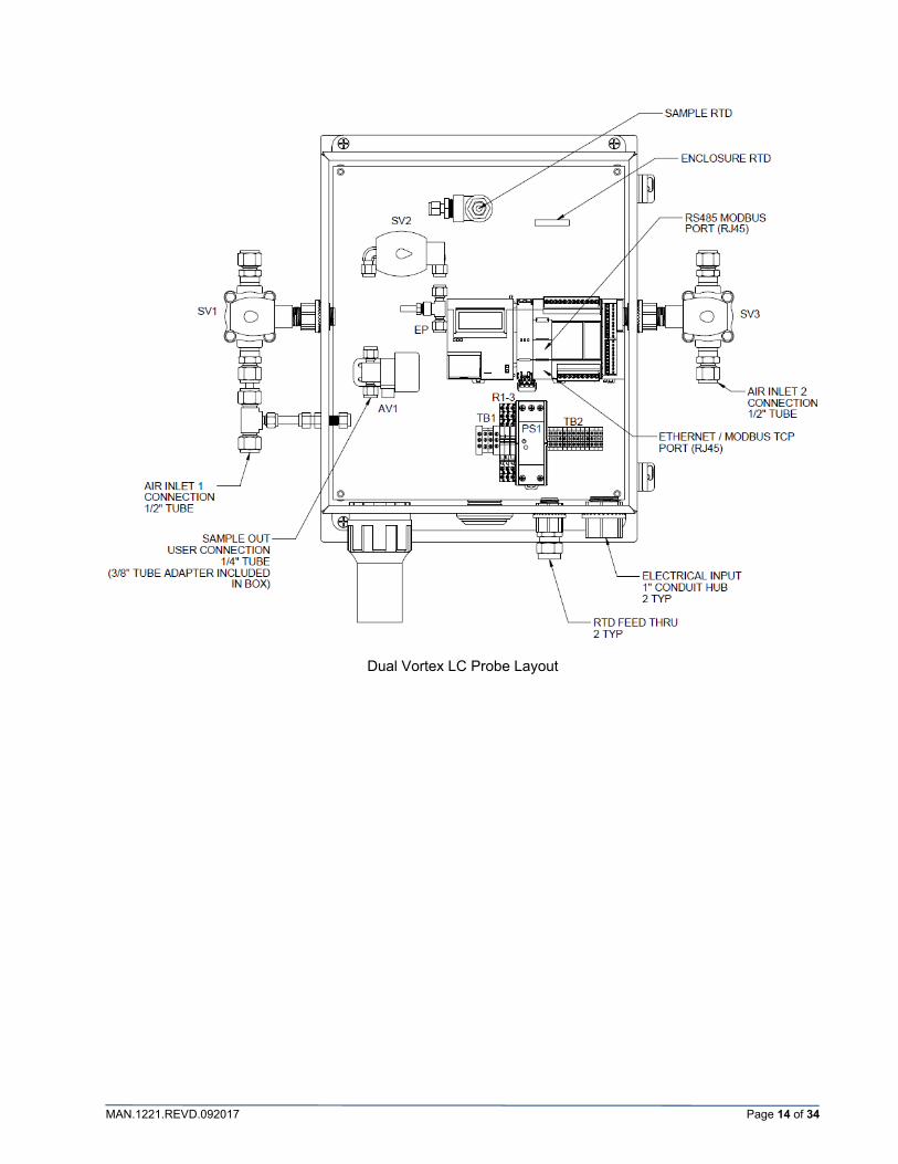
Dual Vortex LC Probe Layout

MAN.1221.REVD.092017 Page 15 of 34
5.2.2 Electronic Controller Overview All electronic controllers are based on the IDEC microSmart FC6A PLC.
RTDs are connected to the PLC via an FC6A-J4CN1, 4 channel input module, located to the right of the PLC. Sensors are connected to the module as follows:
{
{ { { {
Module Power Connection
Sample RTD
Process RTD
Coolant/Exhaust RTD
Enclosure RTD
Input Connections
Status Indicators
Output Connections
Output Power Connection
Power Connection

MAN.1221.REVD.092017 Page 16 of 34
5.2.3 HMI Display and Operation The IDEC FC6A-PH1 provides local control and display, and is located on the left side of the PLC. The Ethernet port located on the bottom side of this module is programmed at the factory: 192.168.1.25. This connection may be used to view and control the PLC from a remote computer, but does not communicate Modbus values and is not practical for usage by most customers.
The screen shown below is the Home screen for the PLC. This screen shows if the PLC is “Running” or “Stopped”, along with the current date and time set in the module. The six buttons used to manipulate and change settings in the PLC are indicated below.
For the purpose of this manual, when text appears in square brackets [ ] this indicates the button on the display module which is to be pushed, and will correspond to the buttons indicated to the above picture. Multiple bracketed texts indicate a sequence of button pushes, in the order in which they are read. Moving from screen to screen requires pushing the [UP] and [DOWN] buttons. Text appearing in ALL CAPITAL letters is related to what is directly written on the PLC display.
When a setting is to be modified, the [OK] button must be held for greater than 3 seconds. This will be indicated as [OK–HOLD].
[OK]
[ESC]
[UP]
[DOWN]
Ethernet Connection Location (bottom)
[RIGHT]
[LEFT]

MAN.1221.REVD.092017 Page 17 of 34
5.2.4 Network and Status Display The FC6A-PH1 has an internal system menu, which displays current information for registers, as well as network. To access the system menu, press [ESC-HOLD] + [OK-HOLD] at the same time. The [ESC] button should be pressed slightly before the [OK] button is pressed.
The DEVICE MONITOR menu provides current values of all internal registers in the PLC. The STATUS MONITOR menu provides network setting information.
5.2.5 Primary Temperature Screen SAMPLE, PROCESS, COOLANT/EXHAUST and ENCLOSURE temperatures are viewed from the primary temperature screen.
No setting changes may be made from this screen, however active alarms and other statuses will be indicated on the bottom row of text, displacing the ENCLOSURE temperature row. The COOLANT/EXHAUST row will display the ENCLOSURE temperature when enclosure alarms are active. The below picture shows the SAMPLE HIGH TEMPERATURE alarm on screen (flashing), before it has been acknowledged.
The alarm message will continue to flash until it has been acknowledged, even if the alarm conditions are no longer present. If alarm conditions are no longer present, and a specific alarm message is flashing, scrolling will be disabled until the message is acknowledged. If a specific alarm message is being displayed and the alarm conditions are still present, scrolling is enabled to view other alarm messages, status messages, and other screens. To acknowledge an alarm, press [OK]. If the alarm conditions are still present, the general alarm message “ALARM” will continue to flash in the bottom row on the screen. Once the alarm condition clears, the general alarm message will clear. The general alarm is always active when any other alarm or NOT OK status is active.
If multiple, specific alarms are present, scroll [UP] and [DOWN] to view the various alarms. Pressing [OK] will acknowledge the alarm being displayed. Repeat until all alarms have been acknowledged.

MAN.1221.REVD.092017 Page 18 of 34
5.2.6 Sample Isolation Valve Manual Operation Screen The sample isolation valve in an electronically controlled probe is a normally closed valve. It requires both power/signal from the PLC and the required air pressure to open the valve to allow sample to flow. The valve will close with loss of either power or air pressure.
The SAMPLE VALVE MANUAL OPERATION screen allows the valve to be forced to remain open or forced to remain closed. These operations override all other PLC controls of the sample valve. The FORCED OPEN command will not open the valve if no air pressure is present.
When FORCED OPEN is enabled, the valve will remain open even if the sample isolation alarm, process isolation alarm, or if the isolation input contact is closed. FORCED OPEN does not enable the general alarm, but does enable Output #6 (not wired to the terminal strip). Typical applications of the FORCED OPEN command include:
Allow process gas to flow across the sample temperature RTD to speed up the startup procedure Get flow to the analyzer under all conditions
When FORCED CLOSED is enabled, the valve will remain shut. FORCED CLOSED enables the general alarm, and “SAMPLE VALVE FORCED CLOSED” will flash on the screen. Typical applications of the FORCED CLOSED command include:
Stop flow during decoke or abnormal conditions Sample line not connected Maintenance activities
The RESET ENTER operation will disable either FORCED OPEN or FORCED CLOSED. The reset register automatically resets itself to zero.
To enable any of the operations on this screen, press [OK-HOLD], [DOWN] to the desired operation, [OK], [RIGHT] 4 times, [UP], [OK]. The FORCED CLOSED sequence is shown below:

MAN.1221.REVD.092017 Page 19 of 34
FORCED CLOSED may not be enabled when FORCED OPEN is currently enabled. Enabling FORCED OPEN when FORCED CLOSED is currently enabled will disable FORCED CLOSED.
CAUTION: If FORCED OPEN is enabled, the PLC cannot automatically shut off the sample flow to avoid a high temperature liquid carryover.
5.2.7 Sample Temperature Setpoints Screen The primary task of the Model 1221 Distillation Probe is to cool the sample gas to the desired temperature. The SAMPLE SETPOINT determines the average temperature of the sample gas, and is programmed in degrees Fahrenheit. Basic operation is to enable cooling when the gas temperature is over the desired setpoint, and disable cooling when it drops below the setpoint. An ALARM BAND is provided to indicate when the temperature is outside of the desired window around the SAMPLE SETPOINT. To help avoid liquid carryover, an over-temperature ISOLATION HIGH setpoint may be configured to close the sample isolation valve when the temperature gets even further beyond the SAMPLE SETPOINT. A HYSTERESIS may be set for situations with a noisy signal or temperature hovers around the sample setpoint and the cooling solenoid valve is opening and closing too frequently.
The ALARM BAND, HYSTERESIS, and ISOLATION HIGH alarms are configured as a difference, or delta, to the SAMPLE SETPOINT. The ALARM BAND is both positive (above) and negative (below) from the SAMPLE SETPOINT. The ISOLATION HIGH setpoint is only positive (above) from the SAMPLE SETPOINT. The HYSTERESIS is only negative (below) the SAMPLE SETPOINT. For example, if the SAMPLE SETPOINT is set at 65°F, and the ISOLATION HIGH setpoint is set at 10°F, the isolation valve will close when the sample temperature reaches 75°F. The ALARM BAND and ISOLATION HIGH alarms have 3 second time delays.
There is always a lag between the cooling cycle operation and response to the sample temperature. This can vary based on process gas temperatures, ambient humidity and temperatures, and process gas flow rates. This is also due to material mass of the probe, properties of the process gases, and inlet temperature of the coolant medium. The greater the lag, the greater the temperature cycles above and below the sample setpoint. The lag creates a temperature “momentum” which pushes the sample gas temperature to the high and low points in the cycle, as much as several minutes after warming and cooling has stopped. The effectiveness of the probe and the setpoints in the controller help to minimize the temperature differential above and below the sample setpoint.
The hysteresis feature drives the cooling temperature down below the sample setpoint by the configured amount. The cooling cycle always starts at the sample setpoint on the up-swing, but will not shut off until the temperature reaches the sample setpoint minus the hysteresis. The effect of hysteresis is shown in the following graph:

MAN.1221.REVD.092017 Page 20 of 34
All the temperature setpoints on this screen are configured with exponential notation. To change any setpoints on this screen, press [OK-HOLD], [DOWN] to the desired setpoint, [OK], [RIGHT] to the appropriate numeral, [UP] or [DOWN] to the desired setting, [OK]. Changing the Sample Setpoint from 65°F to 70°F is shown below:
There are a couple rules for the ISOLATION HIGH setpoint embedded in the PLC.
1. The ISOLATION HIGH setpoint cannot be set less than 5 degrees above the sample setpoint. This helps to avoid unwanted sample valve closures.
2. The ISOLATION HIGH setpoint must always be greater than the ALARM BAND high setpoint. If this situation is detected, the PLC automatically adjusts the ISOLATION HIGH setpoint to be 1 degree above the ALARM BAND high setpoint.
5.2.8 Process Temperature Setpoints Screen The process alarm and isolation setpoints provide warning and sample isolation valve shutoff when the inlet process temperature gets too high. The default factory values for these setpoints are well beyond normal process temperatures, which are essentially turned “OFF”.
Sample Temperature ‐ Cooling Cycle with Hysteresis
Cooling Warming
Sample Setpoint
Hysteresis
Cooling below setpoint

MAN.1221.REVD.092017 Page 21 of 34
To change any setpoints on this screen, press [OK-HOLD], [DOWN] to the desired setpoint, [OK], [RIGHT] to the appropriate numeral, [UP] or [DOWN] to the desired setting, [OK]. Changing the Alarm Setpoint from 1400°F to 250°F is shown below:
5.2.9 Coolant Dwell Timer Operation Screen If the cooling medium is extremely cold (i.e. refrigerant cooled probes) or is more effective at transferring BTUs from the distillation column (i.e. water cooled probes), the cooling cycle can drive sample gas temperatures well below the desired values. Coolant dwell timers may be used to mitigate these special circumstances. The cooling portion of the cycle may be shortened, to stop cooling before the temperature makes it back down to the sample setpoint, where it would normally be shut off.
The dwell timer settings are in units of seconds. When enabled, the COOLANT ON dwell timer starts when the sample termperature rises above the sample setpoint, which coincides with the activation of probe cooling. Probe cooling stops when the timer expires. The COOLANT ON timer should be set to expire while the sample temperature is still above the sample setpoint. The sample temperature should continue to drop below the sample setpoint.
Sample Temperature ‐ Temperature Drop Too Low
Cooling Warming
Sample Setpoint
Temp drops
too low

MAN.1221.REVD.092017 Page 22 of 34
Once the COOLANT ON timer expires, the COOLANT OFF timer begins. It is expected that the sample temperature drops below the sample setpoint before the COOLANT OFF timer expires. If the sample temperature is still above the sample setpoint when the COOLANT OFF timer expires, the COOLANT ON timer restarts, and cooling is enabled again. In this scenario, the COOLANT ON time should be increased or the COOLANT OFF time should be decreased. If the sample temperature rises to more than 5°F above the sample setpoint, the dwell timers are disabled, and cooling remains enabled until it drops back to within 5°F.
Setting the timers should be done empirically, and will be different for each application. Several cycles of testing and adjustments may be required. The sample temperature should always drop below the sample setpoint, but only by an acceptable level.
Dwell timers are typically disabled when shipped from the factory. The timers are disabled when a value of 5 seconds or less is entered in the COOLANT ON timer value.
To change timer settings on this screen, press [OK-HOLD], [DOWN] to the desired timer, [OK], [RIGHT] to the appropriate numeral, [UP] or [DOWN] to the desired setting, [OK]. Changing the COOLANT ON timer to 10 seconds is shown below:
Cooling Cycle with Coolant Dwell Timer
Cooling Warming
Cooling stops
Sample Setpoint
COOLANT ON

MAN.1221.REVD.092017 Page 23 of 34
5.2.10 Enclosure Temperature Screen The enclosure temperature RTD monitors the ambient temperature inside the probe enclosure. This measurement can be critical if ambient temperatures fall outside the operating temperature range of the PLC. The alarming is only applicable when a Local Control (LC) configuration is ordered with the probe. Care should be taken to shade these enclosures from direct sunlight, as well as ensuring that local weather temperatures do not drop below the minimum operating temperature. The operating temperature for the PLC is between 14°F and 130°F, and these are the default values for alarms from the factory.
In addition to alarming, the minimum and maximum enclosure temperature values are stored in the PLC. The “RESET LOG” feature clears the current high and low log values and starts recording at the current temperature. The lowest value that the low log will display is zero.
To change alarm settings on this screen, press [OK-HOLD], [DOWN] to the desired alarm, [OK], [RIGHT] to the appropriate numeral, [UP] or [DOWN] to the desired setting, [OK]. Changing the HIGH Temperature alarm to 110°F is shown below:
When resetting the log values, a “1” is entered. The value resets itself to “0” when complete.
5.2.11 Factory Default Values Screen Unless otherwise specified on the PO when ordered, the electronic controllers are set to specific factory default values. These values are as follows:
Parameter Value Units
Sample Temp Setpoint 65 Deg F
Sample Temp Hysteresis 0 Deg F
Sample Temp Alarm Band 5 Deg F
Sample Temp Isolation Alarm 10 Deg F
Sample Valve Forced Open 0 n/a
Sample Valve Forced Closed 0 n/a
Process Temp High Alarm 1400 Deg F
Process Temp Isolation Alarm 1500 Deg F
Dwell Timer Coolant On 0* Seconds
Dwell Timer Coolant Off 30 Seconds
Enclosure Temp Low Alarm 14** Deg F
Enclosure Temp High Alarm 130** Deg F
Modbus Slave Number 1 n/a
CPU IP Address: 192.168.0.1 n/a
HMI IP Address: 192.168.1.25 n/a

MAN.1221.REVD.092017 Page 24 of 34
*The dwell timers are turned off by default, since the default value is below 5 seconds. **The enclosure temperature alarm values are based on the operating temperatures of the PLC.
To reset the PLC to the factory default values, press [OK-HOLD], [OK], [RIGHT] 4 times, [UP], [OK]. The reset value will automatically reset to 0. The sequence is shown below:
5.2.12 Changing IP Address and Slave Number Scroll [DOWN] to the Home Screen. Press [ESC-HOLD] + [OK-HOLD] to access the system menu. The [ESC] button should be pressed slightly before the [OK] button is pressed. The network settings and slave number may only be changed with the PLC stopped. With the arrow pointing to the “Stop” command, press [OK]. Scroll [DOWN] on the next screen to select “Yes”, and press [OK] to stop the PLC. The PLC will exit the menu and revert to the Home screen, and should display “Stopped”.
Press [ESC-HOLD] + [OK-HOLD] to access the system menu again. The [ESC] button should be pressed slightly before the [OK] button is pressed. Scroll [DOWN] until the arrow points to the “Configurations” selection and press [OK]. Press [OK] to select “Functions”. Press [OK] to select “Communications”. Scroll [DOWN] to the “CPU Network Settings1” screen.

MAN.1221.REVD.092017 Page 25 of 34
To change the slave number, select “Slave Number” by pressing [OK]. Select the Port 1 setting by pressing [OK] (other ports may be selected by pressing [UP] or [DOWN]). The slave number will flash, and may be set by pressing the [UP] or [DOWN] arrows. The slave number may be set as 1 to 247. After the correct number is shown, press [OK].
To change the IP Address of the PLC, after selecting “Communications”, scroll [DOWN] to “CPU Network Settings” and press [OK]. Scroll down once to the “IP Address:” line, and press [OK]. On the IP Address screen, scroll [LEFT] or [RIGHT] to select the proper value, then scroll [UP] or [DOWN] to change the value. Press [OK] to set the IP Address to the new value, and exit back to the CPU Network Settings screen. Press [ESC] to exit out of the settings screen. Scroll down to “Yes” and press [OK] to save the configuration. The Subnet Mask, Default Gateway, and Primary and Secondary DNS server addresses may also be changed in this menu.
Press [ESC] multiple times to exit out of the system menu. Be sure to change the PLC status back to “Run” before exiting.

MAN.1221.REVD.092017 Page 26 of 34
5.2.13 Modbus The PLC is configured at the factory for Modbus RS485 from the serial port, and Modbus TCP/IP from the Ethernet port. The RS485 Modbus RTU Slave serial port is configured at the factory with the following parameters:
Baud Rate 115200
Data Bits 8
Parity Even
Stop Bits 1
Slave Number 1
Max Cable Length 200m
The Ethernet port is configured at the factory for Modbus TCP with IP Address 192.168.1.1 and Local Host Port No. 502.
Modbus Registers
Register Description Value Type Comment PLC
Address
40200 Sample Temp Floating/R Deg F D0200
40202 Process Temp Floating/R Deg F D0202
40204 Vortex Air Exhaust Floating/R Deg F D0204
40206 Enclosure Temp Floating/R Deg F D0206
40208 Sample Temp Setpoint Floating/RW Deg F D0208
40212 Sample Hysteresis Floating/RW Deg F (Delta value) D0212
40214 Sample Temp High Isolation Floating/RW Deg F (Delta value) D0214
40216 Sample Temp Alarm Band Floating/RW Deg F (Delta value) D0216
40316 Process Temp High Alarm Floating/RW Deg F D0316
40325 Coolant Dwell Cycle ON Time Word/RW Seconds D0324
40327 Coolant Dwell Cycle OFF Time Word/RW Seconds D0326
40331 Reset to Factory Values Word/RW 1 = Reset to Factory Defaults (resets itself to 0) D0330
40336 Process Temp High Isolation Floating/RW Deg F D0336
40339 Enclosure Temp Word/R Deg F D0338
40345 Enclosure Low Alarm Setpoint Word/RW Deg F D0344
40347 Enclosure High Alarm Setpoing Word/RW Deg F D0346
40349 Enclosure Low Log Word/R Deg F D0348
40351 Enclosure High Log Word/R Deg F D0350
40353 Enclosure Log Reset Word/RW 1 = Reset Enclosure Logs (resets itself to 0) D0352
40701 Sample Valve Forced Open Bit Word/RW 0 = Normal Operation 1 = Valve Open until Reset D0700
40703 Sample Valve Forced Closed Bit Word/RW 0 = Normal Operation 1 = Valve Closed until Reset D0702
40705 Forced Bit Reset Word/RW 1 = Reset Both Bits (resets itself to 0) D0704
R= read only allowed RW = read and write allowed

MAN.1221.REVD.092017 Page 27 of 34
Output Coil Statuses
Coil Description Staus Comment PLC
Address
00001 Cooling Solenoid Valve 0 = Closed, 1 = Cooling Enables Probe Cooling Q0000
00002 Sample Solenoid Valve 0 = Closed, 1 = Open Enables Sample Flow Q0001
00003 General System Alarm 0 = Off, 1 = Alarm Multiple Alarms Activate Q0002
00004 Sample Temp Alarm 0 = Off, 1 = Alarm Sample High/Low Temp Alarm Q0003*
00005 Encl. Temp / Batt. Alarm 0 = Off, 1 = Alarm Enclosure High/Low Temp and Battery Low Alarm Q0004*
00006 High Process Temp 0 = Off, 1 = Alarm Process High Temp Alarm Q0005*
00007 Sample Valve Forced Open 0 = Off, 1 = Forced Open Sample Valve Forced Open Bit Q0006*
* These outputs are not wired to terminal blocks with standard units.
Input Statuses
Coil Description Staus Comment PLC
Address
10001 Sample Valve Forced Closed 0 = Off, 1 = Closed Shutoff Sample Flow Valve I0000
Serial Port Wiring
The following picture is as viewed from the front of the PLC.
No. Signal Wire (RS-232C)
Signal Wire (RS485)
1 RD - 2 SD - 3 ER - 4 - A 5 - B 6 DR - 7 - - 8 SG SG
Shell* Shield Shield *Shell is connected to PE or FE on the power supply terminals
Note: RS232 communication is not supported by Universal Analyzers. The serial port may be configured to RS232 interface with IDEC WINDLDR software.
MAN.1221.REVD.092017 Page 28 of 34
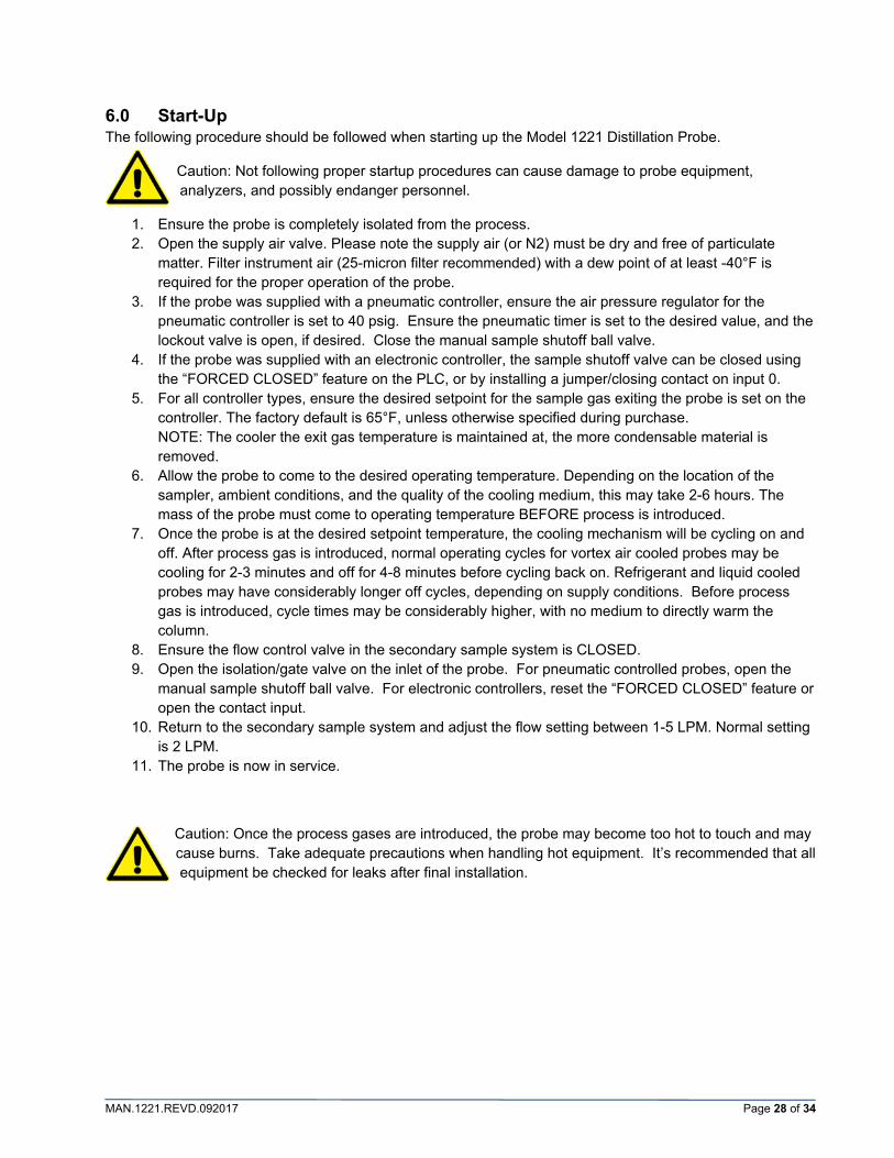
6.0 Start-Up The following procedure should be followed when starting up the Model 1221 Distillation Probe.
Caution: Not following proper startup procedures can cause damage to probe equipment, analyzers, and possibly endanger personnel.
1. Ensure the probe is completely isolated from the process. 2. Open the supply air valve. Please note the supply air (or N2) must be dry and free of particulate
matter. Filter instrument air (25-micron filter recommended) with a dew point of at least -40°F is required for the proper operation of the probe.
3. If the probe was supplied with a pneumatic controller, ensure the air pressure regulator for the pneumatic controller is set to 40 psig. Ensure the pneumatic timer is set to the desired value, and the lockout valve is open, if desired. Close the manual sample shutoff ball valve.
4. If the probe was supplied with an electronic controller, the sample shutoff valve can be closed using the “FORCED CLOSED” feature on the PLC, or by installing a jumper/closing contact on input 0.
5. For all controller types, ensure the desired setpoint for the sample gas exiting the probe is set on the controller. The factory default is 65°F, unless otherwise specified during purchase. NOTE: The cooler the exit gas temperature is maintained at, the more condensable material is removed.
6. Allow the probe to come to the desired operating temperature. Depending on the location of the sampler, ambient conditions, and the quality of the cooling medium, this may take 2-6 hours. The mass of the probe must come to operating temperature BEFORE process is introduced.
7. Once the probe is at the desired setpoint temperature, the cooling mechanism will be cycling on and off. After process gas is introduced, normal operating cycles for vortex air cooled probes may be cooling for 2-3 minutes and off for 4-8 minutes before cycling back on. Refrigerant and liquid cooled probes may have considerably longer off cycles, depending on supply conditions. Before process gas is introduced, cycle times may be considerably higher, with no medium to directly warm the column.
8. Ensure the flow control valve in the secondary sample system is CLOSED. 9. Open the isolation/gate valve on the inlet of the probe. For pneumatic controlled probes, open the
manual sample shutoff ball valve. For electronic controllers, reset the “FORCED CLOSED” feature or open the contact input.
10. Return to the secondary sample system and adjust the flow setting between 1-5 LPM. Normal setting is 2 LPM.
11. The probe is now in service.
Caution: Once the process gases are introduced, the probe may become too hot to touch and may cause burns. Take adequate precautions when handling hot equipment. It’s recommended that all equipment be checked for leaks after final installation.

MAN.1221.REVD.092017 Page 29 of 34
7.0 Maintenance It is recommended that each probe be installed with a gate valve to isolate from process for all maintenance activities.
The coalescing separator is designed to condense and wash the heavy components in the sample back into the process along with any deposited solids avoiding the regular ‘plugging’ that occurs with conventional probes. For this reason, the separator is considered self-cleaning, and but should be inspected at regular intervals. Once isolated from the process pipe, the separator can be removed from the probe without the need to remove the entire probe body.
The separator may be removed in the field by removing the top blind flange, hooking the extractor tool through the lifting ring, and then pulling the assembly out. For electronic controllers, the bottom process inlet RTD must be retracted before the separator may be removed. For pneumatic controllers, the thermometer must be retracted before the separator may be removed. The separator may then be cleaned and re-installed, or a clean, secondary separator may be used instead. The full procedure of cleaning the separator may be completed in 15-20 minutes.
It is recommended to isolate sample flow from the probe during furnace maintenance activities which may cause damage to the probe or analytical equipment.
Caution: If the complete probe is to be removed from the process nozzle and/or gate valve, note that the probe can weigh as much as 150 lbs plus the weight of any remaining, trapped liquids inside. The eye nut and threaded stud should be inspected for tightness before lifting. Note that the eye nut is not directly over the center of gravity. Personnel may be exposed to any liquids trapped inside the probe.
Insulator Cap
Top Flange
Lifting Eye Nut Lifting Ring

MAN.1221.REVD.092017 Page 30 of 34
8.0 Troubleshooting Ensure that vortex cooled probes are supplied with 40 SCFM air at 80-100 psig. Measurements to
ensure this should be made at the probe, not at the supply header. Consider loss in pressure due to supply lines which may be inadequately sized diametrically and/or too long.
Dual vortex cooled probes should be supplied with separate air supply lines for each vortex to avoid inadequate air supply. Each vortex requires 40 SCFM of air.
Instrument air should be clean and dry, with a recommended dew point of less than -40°F. A 25-micron filter is recommended in air supply lines. Air which may condense moisture at higher levels may cause plugging in the vortex tubes, causing a sporadic cooling cycle. If moisture enters a pneumatic temperature controller, the sample temperature setpoint may shift substantially, and the unit should be removed from service and allowed to dry thoroughly.
For pneumatic probes, the bleed tube has a 100-micron diameter hole which may become plugged from a variety of things, such as particulate in the supply air and external oils. Care should be taken to not touch the tip of the bleed tube with skin or any other object. If this becomes plugged, air pressure will bleed off too slowly, causing prolonged cooling cycles and possibly unwanted pneumatic timer valve shutoffs. The bleed tube may be removed and cleaned with alcohol.
Locally Controlled (LC) probes have a limited operating temperature of 14F to 130F. In warm environments, do not install the control box in direct sunlight. An environmental purge is provided which allows instrument air to flow at approximately 1 liter/min to help cool the box. The LC probe should not be installed where ambient temperatures could drop below 14F or area classified heaters would be required. The Remote Controlled (RC) probes are preferred in both situations, where electronics may be installed in temperature controlled shelters.

MAN.1221.REVD.092017 Page 31 of 34
9.0 Spare Parts Pneumatic Controlled Probes
P/N Description Qty
3019-1019 Pressure Gauge 0-100psi Bottom Connect 1
3020-1003 Thermometer 0-250F 1
4954-1087 Bleed Tube 100 micron 1
4955-0090 Manual Valve 2-way 1
4955-1137 Pneumatic Controller 1
4955-1138 Check Valve @ 12psi 1
4955-1139 Air Relay 1
4955-1140 Air Actuated Toggle valve 1
4960-1011 Vortex Tube Muffler Medium 1
4960-1013 Vortex Tube 40SCFM Medium 1
8200-1026 Pneumatic Timer 1
8200-1027 Regulator with gauge 1
Remote Controlled Probes
P/N Description Qty
1150-1049 RTD 6" Length 1/8" Dia Fiberglass Cable 40" Armor 316SS 1
1150-1050 RTD 1" Length 1/8" Dia Fiberglass Cable 30" Armor 316SS 1
1150-1051 RTD 6" Length 1/8" Dia Fiberglass Cable 60" Lead 316SS 1
1150-1052 RTD 1" Length 1/8" Dia Fiberglass Cable 12" Lead 316SS 1
4955-0109 Air Operated Toggle Valve - Normally Closed, 1/4" Tube 1
4955-0260 Solenoid Valve 3-Way 1/4" NPT SS 24VDC Explosion Proof 1
4955-1141 Solenoid Valve 2-Way 1/2" NPT Brass NC Exlosion Proof 1
4960-1011 Vortex Tube Muffler Medium 1
4960-1013 Vortex Tube 40SCFM Medium 1
Local Controlled Probes
P/N Description Qty
1150-1049 RTD 6" Length 1/8" Dia Fiberglass Cable 36" Armor 316SS 1
1150-1050 RTD 1" Length 1/8" Dia Fiberglass Cable 36" Armor 316SS 1
1150-1051 RTD 6" Length 1/8" Dia Fiberglass Cable 18" Lead 316SS 1
1150-1052 RTD 1" Length 1/8" Dia PVC Cable 12" Lead 316SS 1
3152-1014 6A Relay with Fuse, C1D2 3
4955-0109 Air Operated Toggle Valve - Normally Closed, 1/4" Tube 1
4955-0260 Solenoid Valve 3-Way 1/4" NPT SS 24VDC Explosion Proof 1
4955-1141 Solenoid Valve 2-Way 1/2" NPT Brass NC Exlosion Proof 1
4960-1011 Vortex Tube Muffler Medium 1
4960-1013 Vortex Tube 40SCFM Medium 1
5400-1019 Power Supply 24Vdc 60Watt 100-240Vac Input C1D2 1
5600-1251 PLC, FC6A Series 24Vdc C1D2 1
5600-1252 HMI for FC6A, C1D2 1
5600-1253 Analog Input Module, FC6A Series 4-CH (PT100) C1D2 1

MAN.1221.REVD.092017 Page 32 of 34
10.0 Drawings For the current revision of all Model 1221 Distillation Probe drawings, visit the Universal Analyzers website.
www.UniversalAnalyzers.com
Navigate to: Products -> Gas Sample Probes -> Model 1221 Distillation Sample Probe
Links to all current drawings for standard probe configurations are provided at the bottom of the page.

MAN.1221.REVD.092017 Page 33 of 34
11.0 Limited Warranty
1. Limited Warranty. Universal Analyzers, Inc (UAI) offers a limited warranty on each of its products against failure due to defects in material and workmanship for a period ending the earlier of (i) fifteen (15) months from the date of the invoice relating to the sale of the product and (ii) twelve (12) months from the date of installation of the product (collectively, the “Initial Warranty”). During the Initial Warranty, UAI offers a limited warranty against failure due to defects in material and workmanship on each part of a product repaired or replaced by an authorized service person for a period ending the later of (a) the remaining term of the Initial Warranty of the product and (b) ninety (90) days from the date of such repair or replacement. After expiration of the Initial Warranty, UAI offers a limited warranty against failure due to defects in material and workmanship on each part of a product repaired or replaced by an authorized service person for a period ending ninety (90) days from the date of such repair or replacement. UAI further offers a limited warranty that the products and parts it sells will conform to UAI’s written specifications therefor. The foregoing limited warranties cover parts and labor only and UAI does not warrant and will not reimburse the buyer of its products (“Buyer”) for any costs relating to the access by service persons of UAI to the product at issue. The foregoing limited warranties cover only the repair or replacement of defective parts and such determination will be in the sole discretion of UAI. In its sole discretion, UAI may make repairs or replacements under these limited warranties with either new or refurbished parts. To the extent Buyer’s product cannot be remedied under these limited warranties through repair or replacement of parts, Buyer may return the product for a refund of the purchase price, less a reasonable reduction in such purchase price equal to the depreciation expense incurred by Buyer relating to such product. The limited warranties of this Section I.1. are further subject to those warranty exclusions set forth below in Section I.2. 2. Limited Warranty Exclusions. Excluding the warranties provided for in Section I.1., UAI provides all products to Buyer “as-is,” without any other warranty of any kind. UAI disclaims any and all express or implied warranties of merchantability,
fitness for a particular purpose and non-infringement of the intellectual property of others. UAI makes no warranty, express or implied, as to the design, sale, installation or use of its products. UAI’s warranties will not be enlarged by, nor will any obligation or liability of UAI arise due to UAI providing technical advice, facilities or service in connection with any product. There is no warranty by UAI with respect to any product’s: (i) uninterrupted or error-free operation; (ii) actual performance, other than the product’s capability to meet UAI’s specifications therefor; (iii) removal or installation from a worksite or process; (iv) electronic components or associated accessories (including without limitation circuit boards and integrated circuits); (v) maintenance (including without limitation gasket and seal replacements, adjustments, minor repairs and other inspection requirements, preventative or otherwise); (vi) use under inappropriate conditions or not in accordance with operating instructions; or (vii) use in connection with the operation of a nuclear facility. There is no warranty for labor expenses associated with field repairs or the repair or replacement of defective parts in the engine or power unit of any product if such product has been in the possession of the owner or operator for greater than twelve (12) months. There is no warranty for products determined to be, in UAI’s sole discretion, damaged as a result of (a) misuse, neglect or accident; (b) improper application, installation, storage or use; (c) improper or inadequate maintenance or calibration; (d) operation outside of the published environmental specification; (e) improper site preparation or maintenance; (f) unauthorized repairs or replacements; (g) modifications negligently or otherwise improperly made or performed by persons other than UAI; (h) Buyer-supplied software or supplies; (i) use in conjunction with or interfacing with unapproved accessory equipment; (j) use of ABC-style or dry powder fire suppression agents; or (k) leaked sample materials. To the extent a UAI product is used in connection with the operation of a nuclear power facility, Buyer agrees to indemnify and hold UAI harmless from any and all actions, claims, suits, damages and expenses arising from such use. UAI provides no warranty on the oral representations made by its

MAN.1221.REVD.092017 Page 34 of 34
personnel while they are attempting to assist Buyer in the operation of a product. This Standard Limited Warranty does not apply to items consumed by the products during their ordinary use, including but not limited to fuses, batteries, paper, septa, fittings, screws, fuses, pyrolysis, dryer or scrubber tubes, sample boats, furnaces or UV lamps. 3. Non-UAI Products. UAI does not in any way warrant products it does not manufacture except to the extent the warranty of the manufacturer of the product at issue passes through or is otherwise assigned to UAI. If a manufacturer warranty is so assigned to UAI, UAI will only be bound to comply with the length of time associated with such warranty. All other terms of such warranty will be governed by this Standard Limited Warranty and UAI’s General Terms and Conditions incorporated herein by reference. 4. Expenses on Non-Warranty Work. All repairs or replacements by UAI after the expiration of any applicable limited warranty period will be performed in accordance with UAI’s standard rate for parts and labor. Further, if upon UAI’s inspection and review, UAI determines the condition of the products is not caused by a defect in UAI’s material and workmanship, but is the result of some other condition, including but not limited to damage caused by any of the events or conditions set forth in Section I.2., Buyer shall be liable for all direct expenses incurred by UAI to conduct the inspection and review of the product. 5. Exclusive Remedy. The foregoing limited warranty constitutes Buyer’s exclusive remedy with respect to products sold by UAI and UAI’s liability shall be exclusively limited to the written limited warranty specified herein. No employee, representative or agent of UAI is authorized to either expressly or impliedly modify, extend, alter or change any of the limited warranties expressed herein to Buyer. 6. Procedure and Costs. All limited warranty claims must be made in writing promptly following discovery of any defect. Buyer must hold defective products for inspection by UAI. If requested by UAI, Buyer must send the product to UAI for inspection. Any such returns by Buyer will be at Buyer’s expense and Buyer will remain liable for any loss of or damage to the product during such product’s transportation to UAI. No products will be sent to UAI for inspection unless UAI has authorized Buyer to do so.
7. Terms and Conditions. UAI’s General Terms and Conditions are incorporated herein by reference and Buyer accordingly agrees to be bound by the terms thereof. II. Limitations on UAI Liability 1. In General. Buyer agrees UAI shall not be liable for any direct, indirect, incidental, punitive or consequential damages, including lost profits, lost savings or loss of use, whether Buyer’s claim is based in contract, tort, warranty, strict liability or otherwise, which Buyer may suffer for any reason, including reasons attributable to UAI. Buyer agrees these limitations on UAI’s liability are reasonable and reflected in the amounts charged by UAI for its products. 2. Force Majeure. This Standard Limited Warranty does not cover and UAI shall not be liable for either direct or consequential damage caused, either directly or indirectly, as a result of: (i) any act of God, including but not limited to natural disaster, such as floods, earthquakes, or tornadoes; (ii) damages resulting from or under the conditions of strikes or riots, war, damages or improper operation due to intermittent power line voltage, frequency, electrical spikes or surges, unusual shock or electrical damage; or (iii) accident, fire or water damage, neglect, corrosive atmosphere or causes other than ordinary use. 3. Limitation on Warranty Claims. Prior to any obligation of UAI to perform any limited warranty service as set forth herein, Buyer must have: (i) paid all invoices to UAI in full, whether or not they are specifically related to the product at issue; and (ii) notified UAI of the limited warranty claim within sixty (60) days from the date Buyer knew or had reason to know of the defect.